VACUUM FURNACES TECHNICAL CONTENT

Heat Treat Radio #123: Helium Leak Detection Tips for Vacuum Furnace Operators

Helium leak detection is critical to ensure system integrity, product quality, and operational efficiency in vacuum processing. With 36 years of hands-on experience, Dave Deiwert of Tracer Gas Technologies joins host Doug Glenn on the most recent episode of Heat Treat Radio to share a wealth of knowledge on the evolution of leak detection technology, practical maintenance, and best practices for leak testing.

Listeners will gain practical insights into the best leak detection practices and how to troubleshoot challenges.

Below, you can watch the video, listen to the podcast by clicking on the audio play button, or read an edited transcript.



The following transcript has been edited for your reading enjoyment.

Introduction

Doug Glenn: Helium leak detection has come a long way, but not everyone has a brand new piece of equipment. So let’s talk about some of the shortcomings of older equipment and some of the improvements that you’re seeing. 

Dave Deiwert: When I started in 1989, leak detectors pretty much had what were called oil diffusion pumps as the high vacuum pump. That’s the pump that creates the vacuum for the analyzer cell or mass spectrometer so they can separate helium from other gases. These diffusion leak detectors did not like to be shut down improperly or have power outages quite frequently.  

You would hear stories of somebody that turned the power off of a leak detector without a proper shutdown or a power outage, and that could cause an oily mess from the diffusion pump, and maybe even crack the oil. So, you would end up having quite a maintenance event required on the leak detector before you could use it again.  

In fact, these kinds of problems happened so frequently that in my young sales days when turbopump leak detectors first were introduced, as I would go in to show it to a potential client, one of the first questions was, “What happens if you have a power outage?”  

I would have a little fun with that.  

I’d say, “Well, let’s find out.” And I would pull the plug out of the wall, and they would say, “Oh, you can do that?” And of course you could. A turbo pump would just coast down towards a stop. Then we turn the power back on, and it’s back up.  

Part of what compounded this problem with the diffusion pump is that it works by heating oil to jet mist oil vapor that goes to the top, and it’s condensed and directed back down. When power is lost, whether you turn the power off with an improper shutdown or a power outage, that pump is still hot for quite a while. It’s still trying to pump, and the backing pump, whether it’s a diffusion pump or a turbopump, is typically a rotary vane pump. With a power outage or power stop, those pumps will come to a stop very quickly. But those diffusion pumps and turbo pumps are not designed to exhaust atmosphere, so the backing pump or rotary pump comes to a stop pretty quickly, and now you have atmosphere potential on the exhaust of the diffusion pump. 

The turbopump survives that much more nicely than a diffusion pump does. So the first major upgrade in the technology across the board with all the manufacturers was moving away from diffusion pumps to turbo pumps. If you buy a new leak detector from the ‘90s to today, it will very likely have a turbo pump no matter whom you buy it from and even if you buy a used one. 

Size and Portability of Leak Detectors (00:06:09)  

Doug Glenn: How large were these original pieces of equipment? Did you have to wheel them around? 

Dave Deiwert: The very first ones I worked with predominantly would be the size of a washer/dryer. They would typically have casters on so you can roll them around.  
Turbopump Leak Detector
Source: LDS Vacuum Shopper

They took up more space and certainly took up a lot more energy. You could sometimes find what they would call portable leak detectors, but they would still have diffusion pumps in them, and they’d have less features because of how small they were versus the console leak detectors.  

Doug Glenn: So now nowadays they use helium leak detectors. 

Dave Deiwert: Most everybody’s gotten away from console leak detectors. You can find a couple companies that have a fairly large rolls-on-caster leak detector that still has turbo pumps, and higher performing backing/ruffing pumps. But the majority of leak detectors you’re going to find are more portable and smaller in size.  

Doug Glenn: Are they close in size to a briefcase? 

Dave Deiwert: They average 12 to 18 inches wide by 10 to 12 inches deep and 12 to 14 inches tall, approximately. So, much smaller than a washer/dryer. 

Quite frequently, these leak detectors may be sold with a cart so that you don’t have to carry them from point A to point B. It can be a little laborious to still carry them. They weigh 40 lbs or more. So quite often, the first accessory purchased with the leak detector is a cart to roll it around. 

Doug Glenn: So it’s a heavy piece of carry-on luggage essentially. 

Dave Deiwert: Absolutely. 

Maintenance: Old vs. New Leak Detectors (00:06:37)  
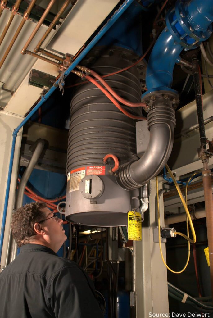
Evaluating a vacuum furnace for leaks

Doug Glenn: How would you compare the maintenance of those older units, assuming that you don’t lose power, versus maintenance of the newer units.  

Dave Deiwert: A stereotypical experience from my field service days would be if you’re running a diffusion pump leak detector in a production environment, using it every day, then most likely you’re going to do what I call an overhaul of the leak detector. During this overhaul, you’re going to change your oils, change the filaments in the mass spectrometer, put on new valve seats, and clean the manifold. 

Not everybody will do this. There are those that might go a year or two, especially if the leak detector is purely for troubleshooting, like if you have only a few furnaces. The leak detector may sit against the wall, and then you go get out to leak test a furnace. They may well get a couple of years of use out of a leak detector before needing to do any preventative maintenance or even a major overhaul.  

With the new turbopump leak detectors, I think all the manufacturers now have models that most likely you’ll go multiple years without really doing anything other than changing oil in the backing pump, which you might do a couple times a year or so, keep an eye on the oil level, much more maintenance friendly and easier to do the troubleshooting and the service to it.  

Filament Technology Improvements (00:08:10)  

Dave Deiwert: The next major upgrade in the leak detectors across the industry was the filament design.  

The old diffusion pump leak detectors predominantly had tungsten filaments, which, if you’ve ever cracked or seen a cracked light bulb that had a tungsten element in it, you know that immediately you lose the function of the light bulb. And the same thing with the filaments that are tungsten in a mass spectrometer. If it gets a pressure burst, which is what I call the event when somebody disconnects the test port from the vacuum furnace while the leak detector is still in test, that allows a pressure burst into the leak detector and tungsten filament, and most likely you will burn out the filament. As a result, you will have a maintenance event for that.  

As a rule of thumb, you will get 1,000 to 2,000 hours out of an old leak detector with tungsten filaments, but you’re going to get many thousands of hours out of a Yttria coated-iridium, which I think is used across the board in the industry today. In the case of  

several years even, it greatly reduces your cost of ownership with the newer leak detectors. 

Performance and Cost Comparison (00:09:12)  

Doug Glenn: Are there any other major differences between the old units and the new units? 

Dave Deiwert: There are some extra benefits from the upgrades that we’ve talked about. The turbopumps will allow, at least modern leak detectors, us to test at a higher pressure (or less vacuum). You press “Start Leak Detector.” The test port pressure pumps down to some vacuum level. For diffusion pump leak detectors, they had to get down to typically less than 50 mTorr. Depending on the model, definitely significantly lower vacuum than the turbopump leak detectors. So, the turbopump ones with the gross leak testing capabilities, you’re probably looking at 18 to 20 torr. I think a couple of manufacturers claim they can get in the test pretty much right below atmosphere and start looking for very massive leaks. 

The capabilities going to turbopump and Yttria-coated filaments has allowed manufacturers to greatly improve the performance and the robustness and reliability of the leak detectors. 

Doug Glenn: In terms of cost comparison, are newer units more or less expensive than older units?  

Weighing the costs and comparisons of different units

Dave Deiwert: When buying a leak detector in 1889 to early ‘90s, you’re probably looking at the low to mid-20s in price. You’re going to find they are a little higher than that now. With the market and inflation, you’re probably looking at upper 20s to low 30s for the most typical leak detectors that are purchased for the vacuum furnace industry. You can find some that are maybe two or three times that amount, but those are not needed for the industries that we’re talking about today. 

Troubleshooting and Service Efficiency (00:11:00)  

Dave Deiwert: If the client, their suppliers, or people who work on the leak detectors from time to time service a diffusion pump leak detector, they may want to explore an idea to troubleshoot a problem. They may not be sure what the problem is yet.  

First, you’re going to do a proper shutdown of the diffusion pump leak detector to protect the oil in the diffusion pump and the cleanliness of the leak detector. You may wait a good part of an hour for that diffusion pump to cool off before you can try the troubleshooting solution you’re going to investigate. Then you’re going to wait for another good hour for it to heat back up and be ready to confirm if what you have tried to do was successful.  

With a turbopump leak detector, you turn a switch off to turn the power off, and within minutes you can test out the solution on the leak detector. So you greatly expedite your troubleshooting time.  

What might have been almost always a full day event of troubleshooting and servicing a diffusion leak detector turns into less than a half day, possibly even an hour or two.  

In every category, the newer leak detectors are very attractive. If clients or our viewers reach out to their suppliers or potential suppliers, there will most likely be some trade-in value for your old leak detector, which will also help offset the pain and suffering of spending money on a new leak detector. 

Doug Glenn: Hopefully they’ll come pick it up, too. 

Where to Connect Leak Detectors on Furnaces (00:14:11)  

Doug Glenn: In your column, you talk about how there’s some debate amongst users on where to hook up the leak detector on the furnace. Can you walk us through that a bit? 

Dave Deiwert: I run into people who are very adamant that you hook up the leak detector in one of three places. And I’ve told salespeople that while we have our preferred location of where to hook to the leak detector, we should never visit a client and tell them they are doing it all wrong. As a field service engineer, I’ve confirmed that you can connect the leak detector at three most prominent locations, but the question is where is the most optimum place to connect it?  

Leak testing a vacuum furnace

The first place is hooking the leak detector directly up to the furnace chamber, because that’s where they imagine the leaks might be. The next two locations might look like close cousins because they’re both in the series flow away from the chamber, through the pumps and out to the exhaust.  

My preferred location is to connect it between the blower and the chamber. Or, if there’s 

a diffusion pump, I would connect it between the blower and the diffusion pump.  

The last place that you might see somebody connect it is between the blower and the backing pump or a roughing pump. They might do this to use the blower almost like a turbocharger to improve the signal to the leak detector. The disadvantage of doing that is most likely these vacuum pumps are very dirty single-stage roughing pumps. There are two concerns I have with this. One is the back stream of oil or hydrocarbons from that pump to the leak detector. And the second is the potential for back streaming, even of helium from the ballast port of the pump or the exhaust, depending on where the exhaust is terminated. If somebody exhausts the pump directly out of the building, then that’s not so much a concern. But if you connect it between the blower and the diffusion pump or the blower and the chamber, then you’re allowing the roots blower to be like an optically dense filter between the leak detector and that backing pump. 

And for the two concerns that I mentioned earlier about either back streaming of helium from the leak testing or back streaming hydrocarbons from the vacuum/roughing pump, the optimal location would be to hook it up between the blower and the chamber, or if it’s a diffusion pump, between the blower and the diffusion pump. If you’re hooking it up between the diffusion pump and the roughing pump, you need to make sure that you pump down to your base pressure before you open up the valve from the leak detector to that point. You don’t want to potentially suck any diffusion pump oil into the into the leak detector. 

Furnace Connection Points and Hardware (00:15:50) 

Doug Glenn: Is there a feed through meant for leak detection built into the furnace, between the blower and the diffusion pump or roughing pump or on the chamber? 

Dave Deiwert: There is almost always a connection point where I describe my preferred location, especially with furnaces manufactured in the last twenty years. On new furnaces sold today, it’ll be an NW25 flange, which will match up directly to the leak detector.  

With the leak detectors in this industry, we’ll have an NW25 flange, which is a standard vacuum connection. You run a bellows hose from that leak detector to that point on the furnace.  

I like to see a manual ball valve that’s always on the furnace at that point. You can put a blank cap on the exposed port on that valve, which can act like a dust cap. It’s always there. This facilitates doing a PM leak check, which we might talk a little bit more about later.  

Now, sometimes you may go to hook it up between the blower and the furnace or the blower and the diffusion pump and there’s no connection there.  

I’ve seen that, so you have to work with what you’re given. You might well see there’s a port between the blower and the backing roughing pump,  

and you can use that. It’s just not the optimal place to put it. 

If you put the leak detector directly on the chamber, typically there’s a small port that you can hook up to, now you’re going to be competing in what we call molecular flow with a much larger opening going to the blower. The lion’s share of helium is going to go out that large target to the blower, and you’re not going to get as much helium signal to the leak detector. So, putting the leak detector port basically right into the end of the flow, going to the blower lets you sample the flow going in that direction. 

Doug Glenn: Right, which is going to be the bulk of it. 

Dave Deiwert: Yes, and you’ll find a faster response time and faster cleanup and recovery of the leak rate signal when you stop spraying the helium by putting it in that location. 

PM Leak Checks During Furnace Operation (00:18:05) 

Doug Glenn: You briefly discussed conducting PM in the column. Can you walk us through conducting a PM leak check during a live operation of the furnace.  

Dave Deiwert: First off, when you’re going to do a preventative maintenance (PM) leak check on the furnace, there are two scenarios. In the first scenario, you’re not running the furnace today. So, you roll the leak detector up and you look for leaks that you may not know are there when they’re smaller and less noticeable, so you can either mark them or repair them at your convenience before they get to be larger and more noticeable, maybe affecting quality of your process.  

The second scenario is that you have a very long process. You might have enough time to do a leak check while the furnace is in process. Helium is an inert gas. If you pull a vacuum on your furnace to do some heat treating, and it’s going to be in that vacuum level for an hour or more, this may be plenty of time to do some leak testing. We definitely don’t want to compromise quality. But again, helium is an inert gas, and if you have an experienced person doing this PM leak check in an orderly fashion, it can be done safely.  

Basically, you roll the leak detector up to that closed ball valve, and you would have to have the ball valve in place there if you’re doing this during a live process. So you connect the hose from the test part to this closed ball valve. You start the leak detector and put it in test. I suggest that after you put it in test, you ensure you have a good vacuum test level vacuum from the leak detector to the closed valve.  

Because we don’t know initially if the vacuum level is different on the other side of the valve, 

Heat Treat Radio #123 Host Doug Glenn and Dave Deiwert

I recommend momentarily stopping the test of the leak detector. I think all modern leak detectors have a standby mode so you’re not venting the test for a leak detector. You put it in standby, then you open the ball valve, and the leak detector computer can now see if the vacuum level changed to maybe potentially a level a little higher than what it wants to be at. That allows it to tell itself to pull some more vacuum along with the furnace before we actually open the test valve to the analyzer cell or the mass spectrometer.  

If you’re in test, you open the ball valve, and somebody forgets that step, there can be a little vacuum differential and you may shock the leak detector and throw it out of test. This doesn’t hurt the leak detector. You just have to go and press test again. But by putting it into standby and then opening the ball valve, then putting it back into test, this saves you a step. 

Once you put it into test, the next thing you’re going to make a note of is the background level of helium before you start spraying helium. I’m a big fan of people who leak test their furnace, or really anything no matter what market is, and take care of their furnaces purposefully.  

If you don’t suspect any leaks or it’s a brand new furnace, you can hook your leak detector up and you put it in test, and before you spray any helium, make note of what I call the background helium signal. This is a result of any natural helium that’s in the furnace. There is five parts per million helium in the air we breathe. There’s going to be helium in the furnace, and take note of what that is.  

Let’s say you notice you have two times ten minus nine background of helium on the display of the leak detector, and you haven’t sprayed any helium, you can make note of that.  

So now you know you’re going to be looking for leaks for some delta change increase of that value. From there, it’s playing the hot and cold game as you pinpoint where the leak isas you spray helium.  

You can do this potentially while a furnace is in process. You certainly want everybody to know what you’re doing and have an opportunity to discuss this because it could make people nervous, especially the quality manager or even the production manager. It’s something that should be talked about with the whole team to ensure everybody sees the value in it.  

So we spray helium and make a note of anything we see. Next time we have an opportunity, when no production is going on, we can fix that leak at our convenience rather than wait until it might get worse. 

Doug Glenn: Certainly we would want to consider whether that should be done with high-value items in the furnace. 

Dave Deiwert: Yes, unless everybody is on board and understands, and you’re doing things purposely.  

If you are doing a PM leak check on a sensitive process and quality of a product and you’re done testing, that manual ball valve needs to be closed before you do anything else to the leak detector. If you forget, and you press vent on the leak detector, it’s going to try to vent that whole furnace through the little vent valve of the leak detector, and that’s not going to be good. 

This whole discussion point is that everybody on the team would need to buy into this idea and be very clear about what we’re going to do, how we’re going to do it. 

I’m just suggesting it’s something that can be done, and if you confirm it works for you, it has value. It’s just another option for somebody to optimize the way they take care of their furnace. 

Confirming Leak Location Before Repair (00:23:38)  

Doug Glenn: When you’re isolating a leak, how important is it to assume or not assume that you found the leak once you get a reading on the on the meter? 

Dave Deiwert: I spend a lot of time on this topic in every class that I teach because nothing is more frustrating than thinking you have found the leak when you haven’t.  

Let’s say you think have found the leak on some big 10-inch gate valve. Maybe it’s too heavy for one person you have to have someone to help you take this gate valve off the system. Once you take the gate valve off the system, you put a repair kit in there, clean everything, you put it back on the furnace, and everything’s assembled. You start to furnace back up and you do a leak check and realize you still have the same leak you thought you fixed. There may be other flanges you need to check, which might require more help.  

You absolutely, beyond the shadow of doubt, can know that you have found the leak because every time helium is sprayed at that place where you think the leak is, you should get the same response, same response time, same peak leak rate.  

If I spray the helium at point A, where I think the leak is at, and I stop spraying, I wait for the leak rate to go back to baseline, then I go back to spray it again. The more work that is involved, the more I’m going to want to duplicate that response and make sure that is where the leak is at.  

Last thing you can do, just to be sure, is what I call the “x, y, z axis.” Try to spray helium left, right, up, down, back and forth, just to make sure you’re not getting a better response to something else nearby.  

Doug Glenn: By better response, do you mean a higher measurement of helium that comes through or comes through more quickly? 

Dave Deiwert: That’s correct. Now, you might have the problem where there are 2, 3, or 4 connections right in the same general area, and it’s difficult to pinpoint where I’m getting I think the same response, no matter where I’m spraying the helium. To remedy this, you can put a barrier between two fittings. This barrier could be plastic, tape, putty, your hand. Try to put some barrier between the two connections so when you spray on one side now, you’re not really getting the same response you were before and can pinpoint the location of the leak more accurately.  

This is an important step before you repair or remove something. If you remove a NW25 flange and you’re wrong, there’s not a lot of pain and suffering. But I guarantee you 100%, you can prove to yourself with some patience and some diligence where the leak is before you do the work of disassembly and service. 

Doug Glenn: It is better to invest a little time in detection than to repair something that doesn’t need to be repaired or find out later that you fixed the wrong piece.  

Dave Deiwert: Absolutely. 

Repair vs. Replace: Leak Source Components (00:26:44)  

Doug Glenn: Once you do find the leak and it’s through some sort of a device, whether it’s a feed through or a control or a valve, how do you decide whether to repair that item or replace it? 

Discerning when to repair or replace

Dave Deiwert: If the device is something that you can disassemble, and if the manufacturer has a repair kit (a valve is a good example of that), I would recommend that you go ahead with a repair. You have already taken it apart, I would put the part in a repair kit, if you have one, to try to lengthen the time between now and the next time you look at it.  

If it’s a piece that has no repair kit, then obviously you will need to repair it or replace it, depending on your skill level and what it is you’re looking at. 

If you’re looking at thermocouple and the feed screws on it are leaking, you may be a little limited in what your options are. Can you apply a vacuum-friendly sealant to brush around the feed throughs to see if that would solve the problem? That may be an option. What is the cost of that thermocouple? If it’s a $20 item, I’m probably going to put another thermocouple on there. If it’s a $1,000 item, I might try brushing some vacuum-friendly sealant on and see if that takes care of the problem.  

One time, I found a leaking rotary vane pump, back in my field service days.  

These all have repair kits where you can replace all the gaskets, the vanes, everything. But I didn’t have one. This was early in my young career. I talked to the factory about getting one and they were going to send one. But I told the client that we had nothing to lose. Let’s open it up, see what we can find. So, we open that pump up, and it looked pretty bad inside, but we cleaned everything up, even the gaskets, put a little vacuum sealant on, and put it all back together. We made it leak tight, and we got it running again. If I had a repair kit, I’m already there, then let’s go ahead and put the repair kit in. But if you don’t have one, there’s nothing wrong with taking it apart and seeing if cleaning and  

reassembly gets it going for you. 

Rotary Vane Pump Field Advice (00:30:30)  

Dave Deiwert:  I’m going to give a little free advice, no extra charge, to people talking about rotary vane pumps. In my career, I’ve come across quite a number of rotary pumps that were having an issue. I can count on one hand, however, how many times I wasn’t able to just clean it, put it back together, and get it going again with fresh oil. And both those times involved a shaft seal leak. So, if you don’t have a shaft seal leak, in my mind, you’ve got nothing to lose by taking a rotary vane pump apart, cleaning it, and putting some fresh oil back in it.  

If you’re using solvents, when you take it apart, make sure those are solvents cleared back out of there  

because solvents and oil don’t play very nice. You want to make sure that solvents have been removed and degassed from your pump. This may require that you put oil in it, run it for a little while, then flush it, and put some oil in to make sure you don’t have anything remaining behind.  

A little willingness to get your hands dirty, open up the rotary vane pump, and a very good chance that you can get it going by just doing that. 

Doug Glenn: All right, Dave. Appreciate the good advice and your expertise. 

About the Guest

Dave Deiwert

Dave Deiwert has over 35 years of technical experience in industrial leak detection gained from his time at Vacuum Instruments Corp., Agilent Vacuum Technologies (Varian Vacuum), Edwards Vacuum, and Pfeiffer Vacuum. He leverages this experience by providing leak detection and vacuum technology training and consulting services as the owner and president of Tracer Gas Technologies. 

Learn more about Dave from Heat Treat Today’s July Digital Edition’s Meet the Consultant page.

For more information: Contact Dave at ddeiwert@tracergastechnologies.com


Heat Treat Radio #123: Helium Leak Detection Tips for Vacuum Furnace Operators Read More »
How To Find Both Real and Virtual Vacuum Leaks

In this Technical Tuesday installment, Thomas Wingens, Founder & President, WINGENS CONSULTANTS; Dr. Dermot Monaghan, Managing Director, and Dr. Erik Cox, Manager of New Business Development, Gencoa, train readers for finding both real and evasive virtual vacuum leaks.

Leak detection is difficult enough with a “real” leak, but “virtual” leaks present their own challenges. To enhance cost savings and further process efficiencies, it’s essential to have leak sensor technology that can effectively monitor the vacuum chamber and pinpoint these problematic leaks.  

This informative piece was first released in Heat Treat Today’s March 2025 Annual Aerospace Heat Treating print edition.


Uncontrolled impurities in a vacuum furnace can significantly affect the quality of vacuum heat treating and brazing processes. They can compromise the integrity of the processed material, leading to defects, reduced performance, and increased costs. 

Real vs. Virtual Leaks 

Real leaks are physical openings in the vacuum system that allow external gases to enter the chamber. These can be cracks, weld failures, improperly installed fittings, faulty seals from damaged or worn O-rings on doors, rotating assemblies, or other components of the vacuum furnace. 

The impact on quality includes: 

  • Oxidation and contamination: Real leaks introduce atmospheric gases (like oxygen, nitrogen, and moisture) into the vacuum chamber, which can lead to oxidation of the materials being treated or brazed, as well as other forms of contamination. 
  • Inconsistent results: The presence of unwanted gases can interfere with the chemical processes required for proper heat treatment or brazing, leading to inconsistent metallurgical results. 
  • Reduced mechanical properties: Contamination and oxidation can weaken the materials being processed, leading to defects and reduced mechanical properties of the final product. 
  • Difficulties in achieving desired vacuum: Real leaks can prevent the system from reaching or maintaining the necessary vacuum levels, leading to longer cycle times or failed processes.  
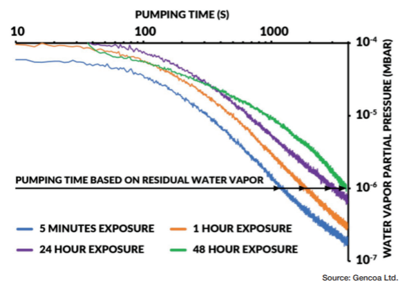
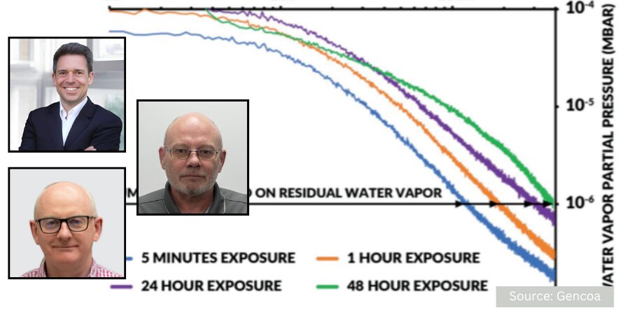
Figure 1. Pumping times based on residual water vapor

Real leaks are often easier to detect, especially larger leaks, which can be identified by hissing sounds or the inability of the furnace to pump down. They can be located using methods such as pressure rise tests, solvent detection, or helium leak detectors. 

Virtual leaks, however, are much harder to detect as they are not physical openings but rather trapped volumes of gas within the vacuum system that slowly release over time. These trapped volumes are typically found in blind holes, porous materials, or unvented components. Even more problematic are leaks from internally sealed systems, such as water cooling or hydraulics. Leaks from these areas cannot be detected via a leak detector, as the water or oil media can “mask” the leak site and prevent the tracer gas from penetrating. 

Aside from increasing the pump time it takes to reach the required vacuum levels, leaks can be a continuous source of contamination within the vacuum chamber. Outgassing can be especially problematic during the heating cycle as it can lead to large vacuum “spikes” or a rise in pressure, affecting the stability of the process environment. Gases released from virtual leaks can contaminate the materials being treated. For example, residual solvents or water vapor from cleaning or incomplete drying can lead to contamination and outgassing. It can be small volumes of air or gas trapped at the bottom of threaded holes or trapped volumes between two O-rings that are not properly vented. Also, outgassing from various hydrocarbons in porous materials such as low-density graphite or powder metallurgy components can release unwanted gases when heated up.  

They usually become apparent during the pump-down cycle when the ultimate pressures are not reached or when it takes a long time to reach blank-off pressure. Traditional leak detectors will not pick up virtual leaks.  

Detecting Virtual Leaks Accurately 

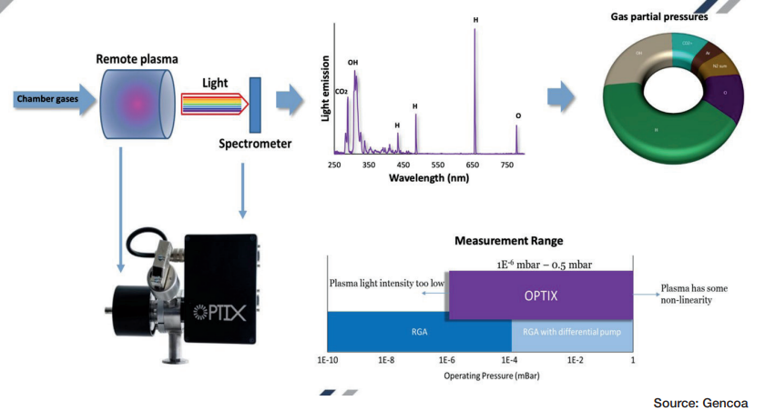
However, residual gas analysis (RGA) and remote plasma emission monitoring (RPEM) can identify virtual leaks by monitoring the composition of gases in the chamber. RPEM offers advantages over traditional quadrupole mass spectrometry (QMS) RGA, particularly in large vacuum systems. Unlike RGAs, RPEM technology operates over a much wider pressure range (50 mbar to 10-7mbar) without requiring additional pumps. The RPEM detector is located outside the vacuum chamber, making it more robust against contamination and high pressures, which commonly damage RGA detectors. This external setup also reduces maintenance needs, as RPEM avoids frequent rebuilds required for traditional RGAs in volatile environments. 

Figure 2. Functionality and pressure range of the OPTIX sensor

An example of this newer sensor is the OPTIX, which enables real-time monitoring and process control by providing immediate feedback to maintain chemical balance and ensure product quality. By identifying specific gas species, the sensor allows versatile leak detection with faster problem-solving and continuous system monitoring. Determining the nature of the gas leak will be a clear indication of where the problem originates. Also, whether the gas levels are stable or decreasing will point towards either a real leak or outgassing problem. Unlike RGAs, this sensor does not require highly skilled staff for operation, further lowering the technical burden. Its effectiveness in harsh environments with volatile species makes it a robust and versatile tool for industrial vacuum processes.

Conclusion 

By understanding the differences between real and virtual leaks, and their specific impacts on vacuum heat treating and brazing, operators can implement more effective detection and prevention strategies, ultimately leading to improved product quality and process efficiency. 

Attention to design, manufacturing, and assembly processes is critical to minimize the occurrence of leaks. This includes proper venting of components, use of appropriate sealing methods, and high-quality welding. Ensuring that components and materials are properly cleaned and dried before being introduced into the vacuum system can reduce outgassing. 

Regular leak checks, including leak-up-rate tests, are essential for identifying both real and virtual leaks. Advanced gas analysis techniques are very useful for identifying the type of leak and its source through analysis of the gases in the vacuum chamber. Th e method provides continuous on-line monitoring, rather than periodic leak testing when there is a “suspicion” of a problem. 

In the demanding environment of vacuum heat treating and brazing, the OPTIX sensor’s advanced technology not only simplifies leak detection and process control, but also delivers significant cost savings through reduced maintenance and operational expenses. Adopting this type of technology gives operators the ability to enhance vacuum system performance, improve product quality, and achieve greater process efficiency.

About The Authors:

Thomas Wingens
Founder & President
Wingens Consultants
Industrial Advisor
Center for Heat Treating Excellence (CHTE)

Thomas Wingens is the Founder and President of Wingens Consultants, and has been an independent consultant to the heat treat industry for nearly 15 years and has been involved in the heat treat industry for over 35 years. Throughout his career, he has held various positions, including business developer, management, and executive roles for companies in Europe and the United States, including Bodycote, Ipsen, SECO/WARWICK, Tenova, and IHI-Group. 

For more information: Contact Thomas Wingens at thomas@wingens.com 

Dr. Dermot Monaghan
Managing Director
Gencoa

Dr. Dermot Monaghan founded Gencoa Ltd. in 1994. Following completion of a BSc in Engineering Metallurgy, Dermot completed a PhD focused on magnetron sputtering in 1992 and went on to be awarded with the C.R. Burch Prize from the British Vacuum Council for “outstanding research in the field of Vacuum Science and Technology by a young scientist.” He has published over 30 scientific papers, delivered an excess of 100 presentations at international scientific conferences, and holds a number of international patents regarding plasma control in magnetron sputter processes. 

Eric Cox
Manager, New Business Development
Gencoa

Dr. Erik Cox is a former research scientist with experience working in the U.S., Singapore, and Europe. Erik has a master’s degree in physics and a PhD from the University of Liverpool. As the manager of New Business Development at Gencoa, Erik plays a key role in identifying industry sectors outside of Gencoa’s traditional markets that can benefit from the company’s comprehensive portfolio of products and know-how. 


How To Find Both Real and Virtual Vacuum Leaks Read More »

Improving Hardening and Introducing Innovation for In-House Heat Treat

Digital tools lead the way in vacuum hardening operations to ensure energy efficiency and processing repeatability. In this Technical Tuesday installment, Paulo Duarte, project manager at Metalsolvus, examines various advantages of wrought versus cast alloys in heat treat operations.

This informative piece was first released in Heat Treat Today's March 2025 Aerospace print edition.


Vacuum hardening has been the chosen process for hardening tools used in plastic injection, die casting, and metal sheet stamping over the past few decades. Although widely used and accepted, there is still room for improvement in tool performance through quality driven procedures. By employing easy methods of measurement, study, and testing, it is possible to enhance part integrity and mechanical properties, while simultaneously reducing heat treatment time and energy consumption. Advanced metallurgical analyses of heat treatment cycles and equipment can introduce better tools on the market, as well as provide time and cost saving heat treatments.

Basics of Vacuum Hardening

Figure 1. Cooling parts in vacuum hardening furnaces — inert gas injection on the hot chamber during cooling

In vacuum hardening furnaces, temperature and time are carefully controlled at specific load locations to ensure optimal hardening. Optimal practices focus on heating and soaking the metal parts during heat treatment. The controlled introduction of vacuum and inert gases during the process ensures the right protective atmosphere for treatment, resulting in steel that is mainly free from oxidation and decarburization. This preserves the surface integrity of the tools.

Cooling is achieved through the injection of an inert gas into the heating chamber, with controlled pressure and adequate recirculation between the heat exchanger and the hot zone (Figure 1). Different gas injection directions are utilized depending on the load being treated, ensuring optimal cooling.

Hardening of Large Tools

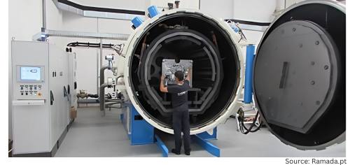
Figure 2. Large molds positioned inside the vacuum hardening furnace, two parallel cavities

Heating and quenching large tools is one of the most challenging situations for vacuum hardening, as temperature control and part microstructure integrity are more difficult to obtain, which affects part quality. Large tools, typically made of hot work tool steels, are hardened in large furnaces. To minimize deformation, parts are preferably positioned vertically inside the furnace (Figure 2).

Surface soaking times for big tools can significantly exceed
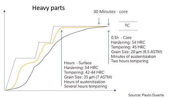
standard austenitization and tempering times due to thermal gradients existing within the parts. Mold cores usually achieve the right soaking and tempering recommendation through accurate temperature control, monitored by well-positioned core thermocouples. A tool’s microstructure and performance will depend heavily on geometry, size, and temperature uniformity achieved during treatment. See Figure 3 for the core and surface typical hardening cycles for large tools.

Figure 3. Heating and soaking cycle for the hardening of large tools (“Heat Treatment of a AISI H11 Premium Hot-Work Tool Steel”)

The cooling phase is crucial in determining the final properties of both the surface and core of the tool. Higher gas injection pressures result in faster cooling and increased toughness, but this also introduces greater deformation risks, when directly cooled from austenitization temperature, so martempering done at low pressures is usually required.

Balancing cooling pressure is one of the most secret topics in vacuum hardening. With a variety of parameters and procedures used among heat treaters, measuring and testing is essential for achieving consistent quality for better controlling the hardening process and attaining the best part quality.

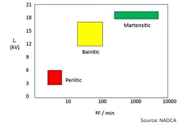
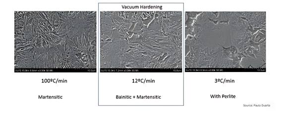
The use of higher or lower inert gas pressures directly affects the cooling rate, making it faster or slower, respectively. Regulating the gas injection pressure during the cooling phase significantly impacts the material’s toughness, even when cooling occurs within the bainitic-martensitic domain commonly observed in vacuum hardening practices. Faster cooling leads to finer microstructures, which in turn results in tougher materials. However, fully martensitic microstructures are rarely achieved in industrial vacuum hardening furnaces and are typically limited to smaller loads composed of small parts. In larger parts, the risk of pearlite formation increases, especially when cooling rates fall around 3°C/min (5°F/min) at the core, as illustrated in Figures 4 and 5.

In industrial heat treatments of large tools, accurately monitoring core temperature is challenging, as it is difficult to position a thermocouple hole exactly at the innermost location or a nearby region. This makes it harder to control the hardening process and prevent pearlite formation. Therefore, studying the process to establish effective control measures is essential for achieving the highest possible
quality.

Figure 6. Mold temperature gradients during vacuum hardening: a) FEM mesh, b) gradients during heating at lower temperatures, c) gradients at the last pre-heating steps, and d) gradients during austenitization from Maia et al. “Study of Heating Stage of Big Dimension Steel Parts Hardening”; e) gradients during mold cooling from Pinho et al. “Modelling and Simulation of Vacuum Hardening of Tool Steels”

Heat treatment simulation simplifies this task by allowing the hardening process to be predicted, with thermal gradients estimated and compensated through furnace control parameter adjustments. Figure 6 presents a real case study, where the temperature distribution inside a large mold was fully characterized during the entire heat treatment cycle using FEM (finite element method) simulation and validated through actual thermocouple measurements. FEM simulation, as a proven and highly effective technique for predicting heat treatment cycles, enables heat treaters to implement optimized, computer-supported heat treatment practices.

Vacuum Hardening Standard Block Size and Cycle Forecast

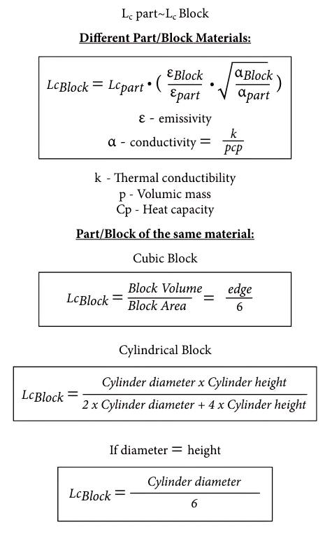
When working with loads composed of small to medium-sized parts, the core temperature of the load can be monitored using dummy standard blocks. These blocks have a central hole to accommodate the thermocouple used to control the heat treatment cycle. The dummy block should be selected to closely match the size of the largest part in the load. However, in commercial heat treatment settings, part sizes can vary widely, making it difficult to maintain a comprehensive set of dummy blocks that represents all possible heat treatment scenarios.

Once again, simulation proves valuable in helping heat treaters gather useful data to anticipate the heat treatment cycle and determine the appropriate range of dummy blocks to have available on the shop floor. The procedure for selecting the dummy block range and forecasting the corresponding heat treatment times is outlined in the following equations. Ideally, the standard block should be made from the same material as the largest part in the load. If the materials differ, the characteristic length of the block can be calculated using the first of the equations to the right.

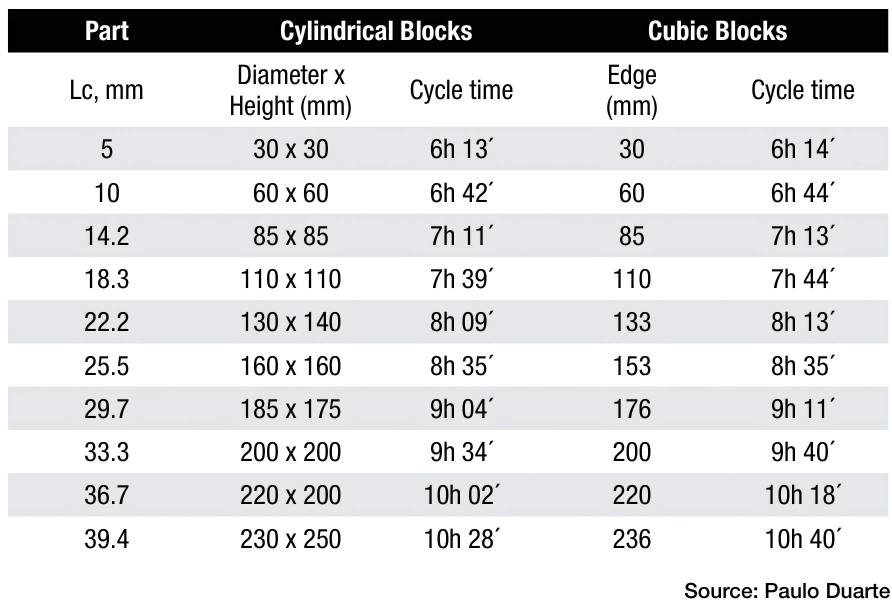
Table 1 lists a range of proposed dummy block sizes to be used for monitoring the load temperature during heat treatment. The time to end of soaking at higher temperature is also given by Table 1 for a typical 600 x 600 x 900 mm hardening furnace. Times were obtained by FEM simulation and can be used to forecast the end of austenitization in a hardening process of each dummy block.

Table 1. Proposed dimensional distribution range for cubic and cylindrical standard blocks and expected cycle times in a typical 600 x 600 x 900 mm hardening furnace (data from Figueiredo et al., “Study of a Methodology for Selecting Standard Blocks for Hardening Heat Treatments”)

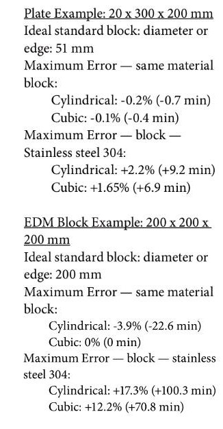
The simulated times were validated by using real parts temperature measurement by thermocouples. These were the calculated errors based on simulation and heat treat validation trial:

Optimizing the Vacuum Hardening of Tools

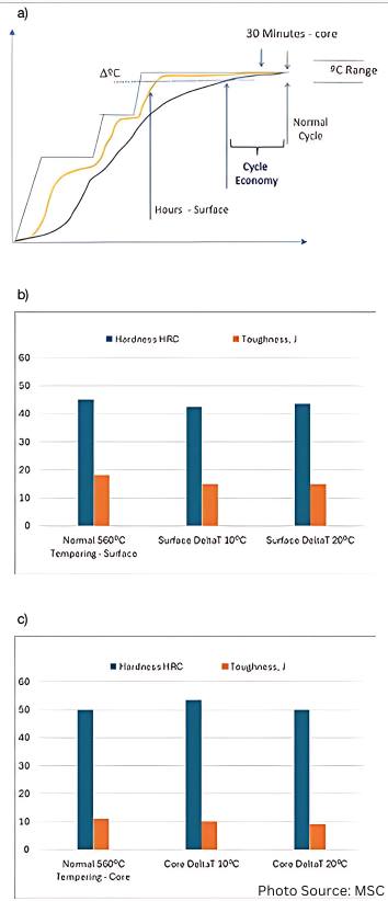
Figure 7. Effect of selecting different temperature (ΔT) range for starting to control the isothermal stage time. a) ΔT criteria and respective cycle time reduction; b) surface mechanical properties obtained by using different ΔT; and c) core properties after tempering at different ΔT range (Miranda et al., “Heat Treatment of a AISI H11 Premium Hot-Work Tool Steel,” MSC)

FEM simulation can also be used to optimize the heat treatment process, but metallurgical testing remains crucial for providing reliable insights into safely reducing cycle time and energy consumption. Typically, for setting the isothermal stage time, a tolerance of -5°C relative to the temperature setpoint is used, leading to savings in both heat treatment duration and power consumption, as shown in Figure 7a. However, Figure 7b demonstrates that higher tolerance values (ΔT) can be considered. Tolerances of up to -10°C or even -20°C can be applied for controlling the soaking time without significantly affecting the hardness and toughness of the parts. Naturally, these results depend on the desired setpoints for the isothermal stages, but Figure 7c reflects the worst-case scenario for ΔT, referring to the use of lower austenitizing and tempering temperatures commonly applied in the hardening of hot-work tool steels.

Future Trends of Vacuum Hardening

Innovations like digitalization, automation, and resource reduction, as part of Industry 5.0 initiatives, are expected to drive advancements in heat treatment processes. Long martempering, a heat treatment under development for hardening hot-work tool steels, shows promise as an alternative to traditional quenching and tempering. This process offers a balance of high hardness and toughness in significantly less time, providing energy savings and faster turnaround.

New Vacuum Hardening Process — Long Martempering

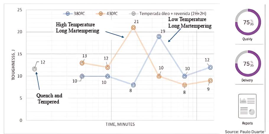
Figure 8. New long martempering heat treatment cycle: AISI H13 premium toughness for two different long martempering temperatures (“Study of The Bainitic Transformation of H13 Premium Steel”)

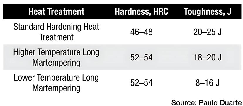
Long martempering is a heat treatment under development that can be used to harden hot-work tool steels. Long martempering is a process somewhat similar to austempering but is applied to steels rather than cast irons. Performed at temperatures within the martempering range, long martempering corresponds to an interrupted bainitic heat treatment with a specific process window (Figure 8) where high toughness is achieved at hardness levels exceeding those obtained through traditional quenching and tempering. Table 2 lists the mechanical properties attained for 5Cr hot-work premium tool steels.

Table 2. Mechanical properties of the new hardening process — long martempering

The transformation during long martempering is not yet fully characterized in terms of microstructure, however, curved needles of bainitic ferrite are observed without carbide precipitation. This phenomenon is generally not associated with steel but rather with ausferrite in cast irons. Nonetheless, it is evident in at least H11 and H13 premium steel grades. This one day martempering treatment could potentially replace the traditional two- to three-day heat treatment cycle for large tools, offering significantly faster lead times and reduced energy consumption. Moreover, the mechanical properties achieved through long martempering are notable, as high levels of both hardness and toughness are obtained simultaneously, as demonstrated in Table 2.

Industry 5.0

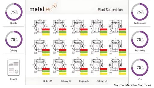
Figure 9. Heat treatment plant supervision solution

The integration of heat treatment equipment with management software enhances furnace utilization, quality control systems, and maintenance practices. Industry 5.0 can be implemented in heat treatment plants through the connection of databases that collect inputs from furnaces (e.g., temperature, time, pressure, heating elements, and auxiliary equipment performance) and production data (e.g., batch numbers, order details, operator information, cycle setup, and load weight). This data is analyzed by software to generate valuable insights for plant management, process optimization, predictive maintenance, and quality control.

A supervision interface for a 5.0 solution can monitor furnaces and control them remotely in real time (Figure 9). Operators receive updates on tasks, alerts, and production schedules. Additionally, plant productivity, efficiency, and maintenance can be tracked through the same supervision software, whether on site or remote. Automatic reporting is also possible, enabling the approval or rejection of cycles based on criteria that are not typically used in heat treatment plants. This not only improves quality but also facilitates process optimization and cost reduction.

Conclusion

Acquiring a full understanding of furnaces in operation through data measurement and analysis allows full control over the heat treatment process. This facilitates process development, enabling cycle optimization and improvement in part quality. Additionally, testing and simulation practices can lead to cost reduction and shorter lead times.

The introduction of long martempering and Industry 5.0 will significantly enhance heat treatment processes, leading to improved delivery times and reduced operational risks. Automation and digitalization bring more data to the shop floor, improving plant management and resulting in greater efficiency, higher quality parts, and simplified task execution.

Finally, current personnel are busy with routine operations that are based on long established practices and may be limiting opportunities for innovation. Therefore, new teams or external consultants can be leveraged to focus on designing, studying, testing, and implementing each new heat treatment solution.

References

Fernandes, José, Laura Ribeiro, and Paulo Duarte. “Study of the Bainitic Transformation of H13 Premium Steel.” MSC thesis, Faculty of Engineering of Oporto University, 2021.

Figueiredo, Ana, Paulo Coelho, José Marafona, and Paulo Duarte. “Study of a Methodology for Selecting Standard Blocks for Hardening Heat Treatments.” MSC thesis, Faculty of Engineering of Oporto University, 2022.

Kind & Co. “Vacuum Hardening with Highest Levels of Precision.” Accessed January 30, 2025. https://www.kind-co.de/en/company/technologies/vacuum-hardening.html.

Maia, Pedro, Paulo Coelho, José Marafona, and Paulo Duarte. “Study of Heating Stage of Big Dimensions Steel Parts Hardening.” MSC thesis, Faculty of Engineering of Oporto University, 2013.

Metaltec Solutions. “Brochure Presentation.” Accessed January 30, 2025. https://www.metalsolvus.pt/en/wp-content/uploads/2019/01/plant-supervision-brochure-V3.pdf.

Miranda, Isabel, Laura Ribeiro, and Paulo Duarte. “Heat Treatment of AISI H11 Premium Hot-Work Tool Steel.” MSC thesis, Faculty of Engineering of Oporto University, 2024.

Pinho, José Eduardo, Gil Andrade Campos, and Paulo Duarte. “Modelling and Simulation of Vacuum Hardening of Tool Steels.” MSC thesis, Aveiro University, 2017.

Ramada. “New Hardening Furnace up to 4 Tons.” Accessed January 30, 2025. https://www.ramada.pt/pt/media/noticias/novo-forno-de-tempera-vacuo---ate-4-tons-.html.

Schmetz. “Schmetz Heat Treatment Furnaces.” Accessed January 30, 2025. https://edelmetal.com.tr/en/heat-treatment-furnaces.

Schmetz. Sketch of the Cooling Process in the Vacuum Hardening Furnace: Schmetz Commercial Proposals Drawing – Metalsolvus Training Courses Documentation.

Seco/Warwick. Vector 3D Hardening Furnace Commercial Brochure.

Solar Manufacturing. “Solar Vacuum Hardening Furnace.” Accessed January 30, https://solarmfg.com/vacuum-furnaces-horizontal-iq-vacuum-furnaces.

Wallace, J.F., W. Roberts, and E. Hakulinen. “Influence of Cooling Rate on the Microstructure and Toughness of Premium Grade H13 Die Steels.” Transactions of the 15th NADCA Congress (1989).

About The Author:

Paulo Duarte, project manager at Metalsolvus, is a researcher and consultant on heat treat technologies. His education and expertise in metallurgy has culminated in several articles and patents. He was a former technical manager within bohler-uddeholm group for the Portuguese market and heat treatment manager with the same group. Currently, Paulo focus on helping heat treaters by providing innovative, more efficient, and profitable heat treatment services to companies.

For more information: Contact Paulo Duarte at paulo.duarte@metalsolvus.pt.


Improving Hardening and Introducing Innovation for In-House Heat Treat Read More »
Why Normalize, and Is a ‘Still Air’ Cool Really Important? Part 2

The Heat Treat Doctor® has returned to offer sage advice to Heat Treat Today readers and to answer your questions about heat treating, brazing, sintering, and other types of thermal treatments as well as questions on metallurgy, equipment, and process-related issues.

This informative piece was first released in Heat Treat Today’s March 2025 Aerospace Heat Treating print edition.


Last time (Air & Atmosphere Heat Treating, February 2025) we addressed the question of why normalizing is necessary. Here we look at the importance of a “still air” cool on the final result. Let’s learn more.

What Is a “Still Air” Cool?

Contact us with your Reader Feedback!

As we learned last month, the term “cooling in air” is associated with normalizing but poorly defined in the literature or in practice, either in terms of cooling rate or microstructural outcome. This lack of specificity has resulted not only in many different interpretations of what is needed, but in a great deal of variability in the final part microstructure.

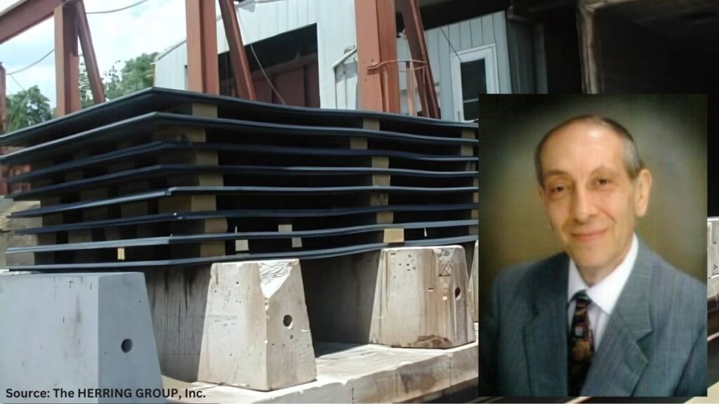
By way of example, this writer has on multiple occasions asked what changes are made to car bottom furnace cycles where cars are pulled outside of the plant for “air cooling” (Figure 1). Questions such as, is the furnace opened and the car pulled out in inclement weather? And, is this practice done on a particularly windy day, or in a rain or snowstorm or when the temperature is below zero? An all-too-common response is, “Only if it isn’t raining ‘too hard’ or snowing ‘too much’; then, we wait a while.” No wonder part microstructures are often found to vary from part to part and load to load!

Most heat treaters agree, however, that normalizing is optimized by a cooling in “still air.” This term also hasn’t been clearly defined, but it will be here based on both an extensive survey of the literature and the most common heat treat practices. In Vacuum Heat Treatment, Volume II, I define a still air cool as: “Cooling at a rate of 40°F (22°C) per minute … to 1100°F (593°C) and then at a rate of 15°F–25°F (8°C–14°C) per minute from 1100°F (593°C) to 300°F (150°C). Any cooling rate can be used below 300°F (150°C).”

Typical car bottom normalizing furnace opening to the outside environment

In addition, many consider nitrogen gas quenching in a vacuum furnace at 1–2 bar pressure to be equivalent to a still air cool. But again, so many factors are involved that only properly positioned workload thermocouples can confirm the above cooling rates are being achieved.

Also, many use the term “air cooling” to differentiate the process from “air quenching,” “controlled cooling,” and “fan cooling.”

Recall from the previous installment of this column that any ambiguity with respect to cooling rate ought to be defined in engineering specifications and/or heat treat instructions so that the desired outcome of the process can be firmly established.

From the literature, several important observations will serve as cautionary reminders. In STEELS, George Krauss points out that: “Air cooling associated with normalizing produces a range of cooling rates depending on section size [and to some extent, load mass]. Heavier sections air cool at much lower cooling rates than do light sections because of the added time required for thermal conductivity to lower temperatures of central portions of the workpiece.”

George Totten’s work in Steel Heat Treatment indicates: “Cooling … usually occurs in air, and the actual cooling rate depends on the mass which is cooled.” He goes on to state:

After metalworking, forgings and rolled products are often given an annealing or normalizing heat treatment to reduce hardness so that the steel may be in the best condition for machining. These processes also reduce residual stress in the steel. Annealing and normalizing are terms used interchangeably, but they do have specific meaning. Both terms imply heating the steel above the transformation range. The difference lies in the cooling method. Annealing requires a slow [furnace] cooling rate, whereas normalized parts are cooled faster in still, room-temperature air. Annealing can be a lengthy process but produces relatively consistent results, where normalizing is much faster (and therefore favored from a cost point of view) but can lead to variable results depending on the position of the part in the batch and the variation of the section thickness in the part that is stress-relieved.

In “The Importance of Normalizing,” this writer offers the following caution: “It is important to remember that the mass of the part or the workload can have a significant influence on the cooling rate and thus on the resulting microstructure.”

Finally, Krauss again observes: “The British Steel Corporation atlas for cooling transformation (Ref. 13.7) establishes directly for many steels the effect of section size on microstructures produced by air cooling.” (Note: Interpretation of continuous cooling transformation (CCT) curves will be the subject of a future “Ask The Heat Treat Doctor” column.)

Since hardness is one of the most commonly used criteria to determine if a heat treat process has been successful, it should also be noted that one can usually predict the hardness of a properly normalized part by looking at the J40 value when Jominy data is available.

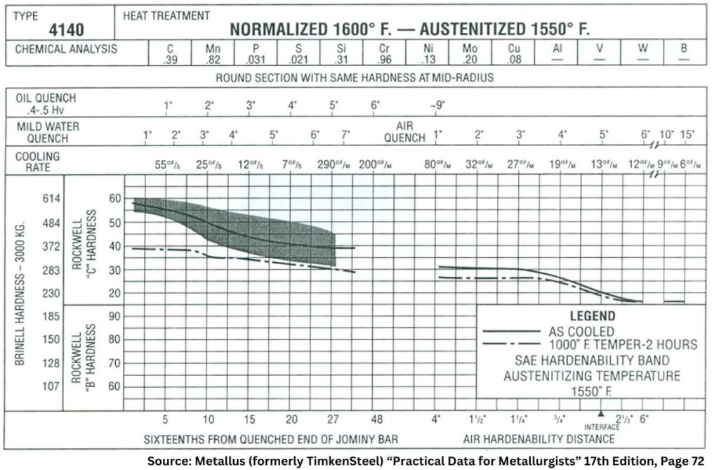
The Metallus (formerly TimkenSteel) “Practical Data for Metallurgists” provides an example of the type of data available to metallurgists and engineers to help define a required cooling rate for normalizing (Figure 2).

All literature references to normalizing agree (or infer) that the resultant microstructure produced plays a significant role in both the properties developed and their impact on subsequent operations.

Figure 2. Combined hardenability chart for normalized and austenitized SAE 4140 steel showing approximate still air cooling rates and resultant hardness (data based on a thermocouple located in the center of the bar diameter indicated)

Final Thoughts — The State of the Industry

It is all too common within the industry for some companies who wish to have normalizing performed on their products to specify only a hardness range on the engineering drawing or purchase order callout that is given to the heat treater.

Industry normalizing practice here in North America varies considerably from company to company. Normalizing instructions are sometimes, but not often enough, provided on either purchase orders, engineering drawings, or in specifications (industry standards or company-specific documents). These instructions range from, in the case of certain weldments, absolutely nothing (i.e., no hardness, microstructure, or mechanical properties) to referencing industry specifications (e.g., AMS2759/1) or specifying complete metallurgical and mechanical testing including hardness and microstructure.

Most commercial heat treaters often perform normalizing to client or industry specifications provided to them. Others prefer so-called “flow down” instructions in which the process recipe is provided to them. It is a common (and mistaken) belief that this removes the obligation of achieving a given set of mechanical or metallurgical properties even if they are called out by specification, drawing, or purchase order.

Also, the final mechanical properties that result from normalizing are seldom verified by the heat treater. Rather, a hardness value (or range) is reported, but hardness is not a fundamental material property, rather a composite value, one which is influenced by, for example, the yield strength, work hardening, true tensile strength, and modulus of elasticity of the material.

References

ASM International. “ASM Handbook, vol. 4, Heat Treating,” 1991.

ASM International. “ASM Handbook Volume 4A, Steel Heat Treating, Fundamentals and Processes,” 2013.

Chandler, Harry, ed. Heat Treater’s Guide: Practices and Procedures for Irons and Steels. 2nd ed, ASM International, 1995.

Grossman, M. A., and E. C. Bain. Principles of Heat Treatment, 5th ed, ASM International, 1935.

Herring, Daniel H. Atmosphere Heat Treatment, vol. I, BNP Media, 2014.

Herring, Daniel H. Atmosphere Heat Treatment, vol. II, BNP Media, 2015.

Herring, Daniel H. Vacuum Heat Treatment, vol. I, BNP Media, 2012.

Herring, Daniel H. Vacuum Heat Treatment, vol. II, BNP Media, 2016.

Herring, Daniel H. “The Importance of Normalizing,” Industrial Heating April 2008.

Krauss, George. STEELS: Heat Treatment and Processing Principles, ASM International, 1990. 463.

Krauss, George. STEELS: Processing, Structures, and Performance, ASM International, 2005.

Practical Data for Metallurgists, 17th ed. TimkenSteel, 2011

Totten, George E., ed. Steel Heat Treatment Handbook, vol. 2, 2nd ed., CRC Press, 2007.

About the Author

Dan Herring
“The Heat Treat Doctor”
The HERRING GROUP, Inc.

Dan Herring has been in the industry for over 50 years and has gained vast experience in fields that include materials science, engineering, metallurgy, new product research, and many other areas. He is the author of six books and over 700 technical articles.

For more information: Contact Dan at dherring@heat-treat-doctor.com.

For more information about Dan’s books: see his page at the Heat Treat Store.


Find Heat Treating Products And Services When You Search On Heat Treat Buyers Guide.Com


Why Normalize, and Is a ‘Still Air’ Cool Really Important? Part 2 Read More »

What Is Thermal Expansion?

The Heat Treat Doctor® has returned to offer sage advice to Heat Treat Today readers and to answer your questions about heat treating, brazing, sintering, and other types of thermal treatments as well as questions on metallurgy, equipment, and process-related issues.

This informative piece was first released in Heat Treat Today’s December 2024 Medical & Energy Heat Treat print edition.


The subject of thermal expansion and contraction is a very important one to most heat treaters given that the materials of construction of our furnaces and our fixtures experience these phenomena every day. However, to find a simple explanation of what it is and how we can help minimize the issues caused by it can be difficult. What we need is an explanation in laymen’s terms, along with some simple science and a few examples. Let’s learn more.

Thermal Expansion Effects

Contact us with your Reader Feedback!

When exposed to a change in temperature, whether heating or cooling, materials experience a change (increase or decrease) in length, area, or volume. This not only changes the material’s size but also can influence its density. The freezing of ice cubes is a common example of a volume expansion (on freezing or cooling), while as they melt (on heating), we see a volume contraction.

As most of us recall from our science classes, as temperature increases, atoms begin to move faster and faster. In other words, their average kinetic energy increases. With the increase in thermal energy, the bonds between atoms vibrate faster and faster creating more distance between themselves. This relative expansion (aka strain) divided by the change in temperature is what is known as the material’s coefficient of linear thermal expansion.

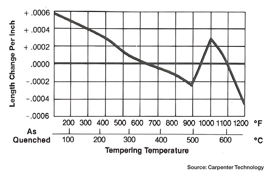
We must also be aware, however, that a number of materials behave in a different way upon heating. Namely, they contract. This usually happens over a specific temperature range. Tempering of D2 tool steel is a good example (Figure 1). From a scientific point of view, we call this thermal contraction (aka negative thermal expansion).

Figure 1. Change in length of D2 tool steel as a function of tempering temperature (Image courtesy of Carpenter Technology — www.carpentertechnology.com)

A related fact to be aware of is that thermal expansion generally decreases with increasing bond energy. This influences the melting point of solids, with higher melting point materials (such as the Ni-Cr alloys found in our furnaces and fixtures) more likely to have lower coefficient of thermal expansion. The thermal expansion of quartz and other types of glass (found in some vacuum furnaces) is, however, slightly higher. And, in general, liquids expand slightly more than solids.

Effect on Density

As addressed above, thermal expansion changes the space between atoms, which in turn changes the volume, while negligibly changing its mass and hence its density. (In an unrelated but interesting fact, wind and ocean currents are, to a degree, effected by thermal expansion and contraction of our oceans.)

What Is the Effect of the Coefficient of Thermal Expansion?

In laymen’s terms, the coefficient of thermal expansion (Table 1) tells us how the size of an object changes with a change in temperature. Specifically, it measures the fractional change in size per degree change in temperature at a constant pressure. Lower coefficients describe lower tendency to change in size. There are several types of thermal expansion coefficients — namely linear, area, and volumetric. For most solid materials, we are typically concerned in the heat treat industry with the change along a length, or in some cases a change in volume (though this is mainly of concern in liquids).

Table 1. Comparative values for linear and volumetric expansion of selected materials

Heat Treat Furnace Examples

When calculating thermal expansion, it is necessary to consider whether the design is free to expand or is constrained. Alloy furnace muffles, retorts, mesh and cast link belts, and radiant tubes are good examples. The furnaces that use them must be designed to allow for linear growth and changes in area or volume. If not, the result is premature failure due to warpage (i.e., unanticipated movement).

If a component is constrained so that it cannot expand, then internal stress will result as the temperature changes. These stresses can be calculated by considering the strain that would occur if the design were free to expand and the stress required to reduce that strain to zero, through the stress/strain relationship (characterized by Young’s modulus). In most furnace materials it is not often necessary to consider the effect of pressure change, except perhaps in certain vacuum furnaces or autoclave designs.

A Little Science

For those that are interested, here are the formulas most often used by heat treaters to calculate the coefficient of thermal expansion.

Estimates of the Change in Length (L), Area (A), and Volume (V)

Linear expansion is best interpreted as a change in only one dimension, namely length. So linear expansion can be directly related to the coefficient of linear thermal expansion (αL) as the change in length per degree of temperature change. It can be estimated (for most of our purposes) as:

where:

  • ΔL is the change in length
  • ΔT is the change in temperature
  • αL is the coefficient of linear expansion

This estimation works well as long as the linear expansion coefficient does not change much over the change in temperature and the fractional change in length is small (ΔL/L <<1). If not, then a differential equation (dL/dT) must be used.

By comparison, the area thermal expansion coefficient (αA) relates the change in a material’s area dimensions to a change in temperature by the following equation:

where:

  • ΔA is the change in area
  • ΔT is the change in temperature
  • αA is the coefficient of area expansion

Again, this equation works well as long as the area expansion coefficient does not change much over the change in temperature ΔT(ΔT), if we ignore pressure and the fractional change in area is small (ΔA/A <<1)ΔA/A<<1. If either of these conditions does not hold, the equation must be integrated.

For a solid volume, we can again ignore the effects of pressure on the material, and the volumetric (or cubical) thermal expansion coefficient can be written as the rate of change of that volume with temperature, namely:

where:

• ΔV is the change in volume
• ΔT is the change in temperature
• αV is the coefficient of volumetric expansion

In other words, the volume of a material changes by some fixed fractional amount. For example, a steel block with a volume of 1 cubic meter might expand to 1.002 cubic meters when the temperature is raised by 90°F (32°C). This is an expansion of 0.2%. By contrast, if this block of steel had a volume of 2 cubic meters, then under the same conditions it would expand to 2.004 cubic meters, again an expansion of 0.2% for a change in temperature of 90°F (32°C).

Thermal Fatigue

In many instances, we must consider the effect of thermal fatigue as well as thermal stress. One example is on the surface of a hot work die steel as H11 or H13: one must ensure that in service, when it experiences a (rapid) change in temperature, it will avoid cracking.

The equation for thermal stress is:

where:

  • σ is the thermal stress
  • E is the Young’s modulus of the material at temperature
  • α is the coefficient of linear thermal expansion at temperature
  • ΔT is the change in temperature

Here both E and α depend on temperature and the resultant stress will either be compressive if heated or tensile if cooled, so we must use these constants at both maximum and minimum temperatures. Considering the temperature dependent stress-strain curve, this stress may exceed the elastic limit (tensile or compressive) and contribute eventually to thermal fatigue failure. There are software programs to aid in the calculation of the resultant thermal stresses. Thermal expansion at a surface at a higher temperature than the core results in a compressive stress, and vice versa.

Final Thoughts

The effects of thermal expansion will be highlighted in a forthcoming article in Heat Treat Today, but it suffices for all heat treaters to remember that this phenomenon is responsible for a great deal of downtime and maintenance in our equipment. It also can affect the end product quality (disguising itself as distortion) and hence create additional cost or performance issues for our clients.

References

Chandler, Harry, ed. Heat Treater’s Guide: Practices and Procedures for Irons and Steels, 2nd Edition. ASM International, 1995.

Herring, Daniel H. Vacuum Heat Treatment. BNP Media, 2012.

Herring, Daniel H. Vacuum Heat Treatment Volume II. BNP Media, 2016.

Special thanks to Professor Joseph C. Benedyk for his input on the topic.

About the Author

Dan Herring
“The Heat Treat Doctor”
The HERRING GROUP, Inc.

Dan Herring has been in the industry for over 50 years and has gained vast experience in fields that include materials science, engineering, metallurgy, new product research, and many other areas. He is the author of six books and over 700 technical articles.

For more information: Contact Dan at dherring@heat-treat-doctor.com.

For more information about Dan’s books: see his page at the Heat Treat Store.


Find Heat Treating Products And Services When You Search On Heat Treat Buyers Guide.Com


What Is Thermal Expansion? Read More »

The Heat Treat Robotic Paradigm Shift

As Thomas Bauernhansl, professor of Production Technology & Factory Operations at the University of Stuttgart, aptly states, “We are going from more supply-oriented production to a demand-oriented one. In many cases, the customer determines which version he wants to have [of] a product — the manufacturer adapts to this and his processes accordingly.”

This shift is critical for the heat treat industry, where the need for advanced automation and robotics integration is paramount to achieve higher efficiency, consistent quality, and reduced costs. In this Technical Tuesday, Dennis Beauchesne, general manager at ECM USA, discusses the increase in use and installation of automation and robotics in manufacturing and specifically how companies within the heat treat industry have adapted to their implementation—and become innovators in their usage.

This informative piece was first released in Heat Treat Today’s January 2025 Technologies To Watch in Heat Treating print edition.


Industry Automation

In the last 10–15 years, an upward trend is consistent with the increased investment value of integrated automation within a heat treatment plant. At the beginning of the 2000s, it was common to have an automatic transport car transporting batches to different stations, but, in the last five years, far more complex automation solutions are in demand. In order to meet the requirements of future industry robotics and automation, our industry must adapt to the new and improved technology offerings and standards that are being used in other industries.

Figure 1. Annual robotics installation by industry 2021-2023

According to World Robotics, there has been a significant increase in robotics usage and installations since 2020 (Figure 1). For example, the automotive industry shows installations almost doubled from 2020 to 2022 with 83,000 installations in 2020, compared to 136,000 installations in 2022. The industrial robot market was expected to grow by 7% in 2023 to more than 590,000 units worldwide. Although it exceeded 500,000 installations, robotics were down 2% (possibly due to COVID-19) compared to the prior record year. Of interest to note for the automotive industry, the industry increased its robotics demand in 2023 to surpass electronics with a 25% share (electronics was close with 23%, down by 5% due to inventory levels stabilizing after supply chain bottlenecks mostly vanished).

Table 1. North America’s robotics comparison 2022 to 2023
Source: World Robotics

Specifically for the United States and Mexico, peak robotics installation demand was documented in 2022, but demand has been consistent within +/-5% (Table 1). The future of robot installations is trending to grow and exceed 50,000 units in North America for 2024. Nearshoring of supply chains will create demand for automation technology in the years to come, according to Christopher Müller in his World Robotics 2024 – Industrial Robots presentation.

Manufacturing Concepts

The company SEW has previously published its ideas and concepts of autonomous transporters distributing the raw parts to the production cells, after the soft processing to the hardening plant, and finally the hard machining (Figure 2). All steps are configured within the component so the process steps can be well documented on a component basis.

Figure 2. SEW concept from Hiller, “The networked hardening shop,” 2019
Source: ECM GmbH

As can be seen in the SEW Figures, the original hardening plant is shown as a continuous furnace. However, this type of plant technology can be seen as contradictory to current production needs. To be compliant with this new philosophy, plant technology must be as modular, flexible, and automatable as the rest of the production layout and components. Heat treatment must also be controllable and unloadable with automatic transport units. Robots must be able to load batches and navigate the plant (according to CHD, steel, part numbers, etc.). The smaller the batch size, the larger the value of robotic component documentation. Furthermore, a reduction in batch size is advantageous for flexibility, costs, and heat treatment of many requirements for production runs.

Heat Treatment & Robotics

A heat treatment plant can implement
recommendations for the future of industry
automation by acquiring technology for:

  • Automatic loading/unloading
  • Component recognition systems
  • Automatically loaded/read recipe systems
  • Smaller batch sizes with a wide variety of variants
  • Heat treatment of different applications or steels in small quantities
  • Maintenance/repair detection

Benefits of automating part or all production line steps include:

  • Shorter process times
  • High CHD (Case Hardening Depth) uniformity and lower distortion
  • Lower operating costs and labor reduction

These technologies have existed and are being implemented in heat treat operations for a few years now. The results are clear and the benefits are proven through higher quality parts, highly efficient heat treat operations, and overall more efficient production facilities.

As many machining operations have been robotized, this allows the downstream heat treat operations to easily take advantage of part placement in dunnage and plant transport systems, whether manual or automated.

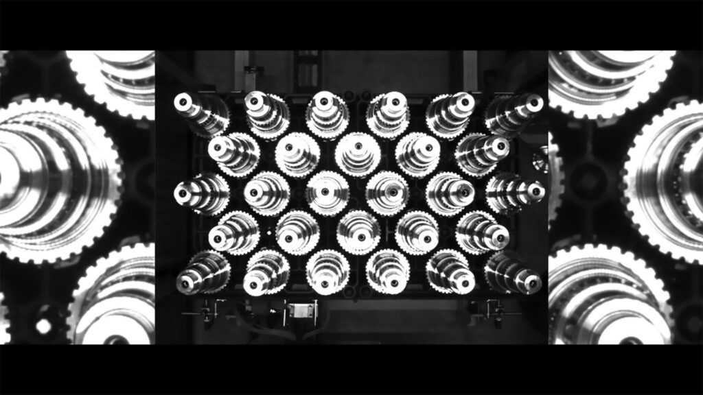
Figure 3. ECM Vision System
Source: ECM Robotics

Batch Loading with Robotics

Bulk goods-loading (such as clips, links, and other small parts via weight detection) as well as loading and unloading of truck shafts in fixtures and in straightening machines are just a few examples of production areas that can benefit from robotics/automation. Visual recognition systems can identify gears/parts based on the diameter or by the number of teeth on the gear and can then sort them by these features (Figure 3).

Like the visual locating of the parts by cameras, they can also be used for tracking parts and loads within a heat treatment cell. A good amount of work has been done in this area for heat treating. This work covers part marking, tray/fixture encoding, and part weighing scenarios, and allows the heat treat system to accurately process all the different parts coming through the heat treat system with the correct process recipe.

Some of the work being done has been implemented with a QR code marking system for each part before heat treatment. To ensure the correct recipe or heat treatment is performed on the proper part, this scanned code works with the heat treatment system controls to upload the correct recipe to the proper cell. This information can be further analyzed to indicate precise placement in the heat treat tray through virtual tracking.

Figure 4. QR code heat treat test picture
Source: ECM USA Synergy Center

In Figure 4, you can see in the details that this client has reviewed and tested to assure the code is visible before and after heat treating with a carburizing and hardening process.

These parts are tracked when entering the system and also noted as to which heat treat tray they are on by using a binary code with holes in a tray or on a strategically placed bar code plate on the tray. With this system, they can be scanned by a camera before entry and upon exit of the furnace (Figure 5). This tray scanning can also indicate how many cycles the trays have on them to ensure the trays stay in good condition and can be cycled efficiently.

Figure 5. Lohmann Steel barcode scan plate (Images courtesy of Lohmann Steel, heat resistant castings — grates, trays, baskets, fixtures and more)
Source: Lohmann Steel

Networked Hardening

Let’s look at the SEW production concept again and re-imagine it with a more efficient vacuum furnace technology with robotic integration. In this concept, the vacuum furnace system forms the “spatially distributed production reserve” which helps autonomous transport units as “situationally self-controlling” material is delivered.

The QR code on the component represents the “knowledge-based” running card. The robots recognize the components by means of the QR code and are loaded onto the appropriate heat treat trays. The heat treatment can then be carried out on a component-related, flexible, and documented basis. Traceability of production can also be ensured (Figure 6).

Figure 6. Robotics concept
Source: ECM Technologies

Loading of the parts can be done efficiently through a series of dunnage that hold the part in specific locations which assist the robot to locate, lift, and place the parts in the heat treat tray. This method doesn’t always need to be a perfect location for the incoming work as we now have 2D and 3D cameras that can work in tandem to locate parts, even in odd stacking or randomly loaded bins.

In a recent installation, a heat treater automated their gear cutting operation to prepare the dunnage before heat treat. Therefore, the heat treat robotics phase was simplified by storing each part in a specification location for the robot to “see” with its vision system. These parts are then scanned and automatically connected to the part’s recipe as stored in the system. In a modular system using low pressure carburizing, individual cells are utilized, and production is recipe driven. These recipes are pre-developed and stored to allow each cell to utilize the recipes for many different parts. In this case, after a part is scanned, the recipe is uploaded into the next available cell and the scanned parts and heat treat fixture is moved to the cell (Figure 7).

Figure 7. Modular vacuum furnace for low pressure carburizing
Source: ECM USA

Figure 8 was designed to use over 175 different parts with nine different heat treat processes which included carburizing and slow cooling, hardening, tempering, cooling after tempering and cryogenic treatment.

With further considerations for additional benefits of the automated system, fixtures were optimized by using CFC (carbon fiber composite) base trays. These trays are not only extremely stable and have non-existent growth/warpage, but they also help with robotic placement before and after heat treatment. CFC trays are flat, or can be machined to conform to part geometry, which helps to reduce or minimize distortion related to fixture warpage or creep.

Figure 8. LPC and robotics configuration
Source: ECM USA

Many system designs have been proposed to a variety of clients; however, the end goal is to design a system that is “standard.” This standard design needs to incorporate different forms of dunnage, bins, boxes, and pallets to allow a commercial heat treater to easily program the system whenever the next part comes in from their client, whatever it may be. This is a challenging task and needs to be broken out by weight category to design the robot’s reach and end tool design. In this case a robot cell offline of the heat treat furnace can be built and utilize, and ultimately use, an AMR (automated mobile robot) or AGV (automated guided vehicle) to bring the built loads to the furnaces (Figure 9).

Figure 9. AGV configurations
Source: ECM GmbH & ECM Technologies

Vacuum Advantages

Vacuum furnace systems have a clear advantage over traditional atmospheric systems with many features which lend themselves to integrate into the machining area with robotics and automation.

The fact that an LPC (low pressure vacuum) furnace system can process loads via a recipe input and each cell can be used to process a different case depth, or hardening cycle is highly advantageous when processing a wide variety of parts. In addition, the LPC process provides a more uniform case depth throughout the part to make a stronger part along with high quality processing. The vacuum furnace cells can be arranged in many ways to fit into existing facilities and to be able to use many methods of automation especially including robotics.

Quenching is also a key element in any hardening heat treat process. LPC furnace systems are usually associated with high pressure gas quenching (HPGQ) in a separate chamber to provide the best quenching performance. This gas quenching technique provides a clean process for each part and allows the use of CFC fixtures. There is also no requirement for post cleaning as is necessary with oil quenching.

Providing quality low pressure carburizing, clean and precise gas quenching, CFC trays for better uniformity and keeping the parts flat, and the automation benefits of robotics makes for a state-of-the-art heat treating production operation and thus completes the heat treat paradigm shift.

Figure 10. Robot loading
Source: ECM USA

Conclusion

The heat treat industry wants and needs automation and robotics integration to advance production, reduce costs, and improve the overall quality of production. With traditional technology, process data evaluation and self-configured recipe values are not possible. Therefore, component analysis should be automated to meet and achieve consistent and reliable recipe values (mass flow, time). With the increase in robotics demand, vacuum furnace technology meets the variable requirements of “demand-oriented” production. Due to the flexibility of this technology, small batch size systems can be automated with robots or as bulk material.

References

  • Hiller, Gerald. “The networked hardening shop – the challenge to the hardening plant in the world of Industry 4.0.” ECM GmbH. Paper presentation, 2019.
  • Müller, Christopher. “World Robotics 2024 – Industrial Robots.” IFR Statistical Department, VDMA Services GmbH, presentation in Frankfurt am Main, Germany, 2024.

About the Author:

Dennis Beauchesne
General Manager
ECM USA

Dennis Beauchesne brings experience of over 200 vacuum carburizing cells installed on high pressure gas quenching and oil quenching installations. He has worked in the thermal transfer equipment supply industry for over 30 years, 23 of which have been with ECM USA.

For more information: Contact Dennis at DB@ECM-USA.com.


The Heat Treat Robotic Paradigm Shift Read More »
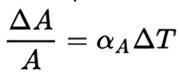
Understanding Inductance in a Furnace Heating System

In this installment of the Controls Corner, we are addressing inductance in a furnace heating system, and the critical role it plays in various industrial systems, including furnace load systems. Impedance acts as a measure of how much a circuit resists the flow of AC current. In this guest column, Brian Turner, sales applications engineer at RoMan Manufacturing, Inc., explains how impedance applies in electrical circuits.

This informative piece was first released in Heat Treat Today’s November 2024 Vacuum Heat Treat print edition.


Inductance is a fundamental concept in electrical engineering, and it plays a critical role in various industrial systems, including furnace load systems. In furnaces used for heating, inductance is a key factor influencing the system’s electrical performance, energy efficiency, and overall operational behavior.

To talk about inductance, let’s first address impedance and how it applies:

In electrical circuits, impedance refers to the total opposition to the flow of alternating current (AC), which is a combination of both resistance (from resistors) and reactance (from inductors), essentially acting as a measure of how much a circuit resists the flow of AC current, taking into account both the resistive component (like a resistor) and the reactive component (like an inductor at a specific frequency) within the circuit.

Load configuration, power source (IGBT, VRT, ERT) to the furnace feedthrough
Source: RoMan Manufacturing Inc.

Inductance

Inductance is the property of an electrical conductor that opposes a change in the current flowing through it. It arises from the magnetic field generated around the conductor when an electric current passes through it. The unit of inductance is the Henry (H).

In an AC circuit, inductance creates a phenomenon known as inductive reactance, which resists the flow of current. Inductive reactance (XL) is given by the formula:

XL = 2πƒL

Where:
• XL is the inductive reactance (in ohms)
• f is the frequency of the AC supply (in hertz)
• L is the inductance (in Henrys)

This reactance influences how the current behaves in the system, which is particularly important in furnace load systems where high current flows are common.

Resistance

Electrical resistance is the opposition that a material offers to the flow of electric current. It is measured in ohms (Ω) and depends on factors such as the material’s properties, its temperature, and the geometry of the conductor (length, cross-sectional area). In heating systems like vacuum furnaces, resistance is harnessed to convert electrical energy into heat through Joule heating (also known as resistive heating).

The relationship between electrical power, voltage, current, and resistance is governed by Ohm’s law:

V = IR

Where:
• V is the voltage across the heating element(in volts)
• I is the current through the element (inamperes)
• R is the electrical resistance of theelement (in ohms)

The heat generated by the furnace’s heating elements is a function of the power dissipated in the resistance, given by the equation:

P = I2 x R

This shows that the heat produced is directly proportional to the resistance and the square of the current flowing through the heating elements

Close Couple

  • Reducing the material in the secondary* reduces resistance (HEAT = I2 x R)
  • Reducing the area in the secondary reduces inductive reactance increasing power factor

To be most efficient, use the shortest amount of conductor material from the electrical system secondary to the furnace feedthrough. Additionally, keep the distance between those conductors as small as possible.

Power Factor and Efficiency

Inductance in a furnace load system causes the current and voltage to be out of phase. This phase difference results in a lower power factor, which is a measure of how effectively the system converts electrical power into useful work. A lower power factor means that more apparent power (the combination of real power and reactive power) is required to achieve the same level of heating.

In practical terms, a furnace with a high inductive load will draw more current from the power supply for a given amount of heating, leading to increased energy losses and inefficiency.

In practical terms, a furnace with a high inductive load will draw more current from the power supply for a given amount of heating, leading to increased energy losses and inefficiency. Power factor correction techniques, such as the use of capacitors, are often employed to counteract the effects of inductance and improve system efficiency.

Conclusion

Inductance is a fundamental factor in the operation of furnace load systems, influencing everything from heating performance to energy efficiency and power quality. By understanding and managing inductance, furnace operators can optimize their systems for maximum performance while minimizing energy losses and operational costs. Controlling inductance is essential for ensuring that furnace load systems operate reliably and efficiently in demanding industrial environments.

*The connection from a vacuum power source to the furnace’s feedthroughs, this connection can be made using air-cooled cables, water-cooled cables, or copper bus.

About the Author:

Brian Turner
Sales Applications Engineer
RoMan Manufacturing, Inc.

Brian K. Turner has been with RoMan Manufacturing, Inc., for more than 12 years. Most of that time has been spent managing the R&D Lab. In recent years, he has taken on the role as applications engineer, working with customers and their applications.

For more information: Contact Brian at bturner@romanmfg.com.


Understanding Inductance in a Furnace Heating System Read More »
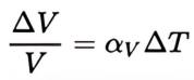
Anatomy of a Front-Loading Vacuum Furnace

Contact us with your Reader Feedback!

How well do you know the “anatomy” of your key heat treat equipment? In this “Anatomy of . . .” series, industry experts indicate the main features of a specific heat treat system. In this installment, the full-page spread identifies main features of a front-loading vacuum furnace.

The mark-ups for these reference images are provided by Jim Grann, technical director, Ipsen.

View the full graphics by clicking the image below.

This Technical Tuesday article is drawn from Heat Treat Today’s November 2024 Vacuum print edition with a special focus on vacuum furnace technologies.

Search www.heattreatbuyersguide.com for a list of vacuum furnace providers to the North American market. If you are a vacuum furnace supplier and are not listed here, please let us know at editor@heattreattoday.com.

This series will continue in subsequent editions of Heat Treat Today’s print publications. Stay tuned!


Find Heat Treating Products And Services When You Search On Heat Treat Buyers Guide.Com

Anatomy of a Front-Loading Vacuum Furnace Read More »
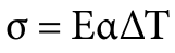
The Future of Vacuum Oil Quenching

Despite years of research and development that resulted in several important technological innovations, the constraints of high-pressure gas quenching are ever more evident. In today’s Technical Tuesday, Robert Hill, FASM president of Solar Atmospheres of Western PA, addresses the creation of a new, robust style of vacuum oil quench furnace. The results challenge the schematics in how the next generation of oil quench furnaces should be designed, built, and operated.

This informative piece was first released in Heat Treat Today’s November 2024 Vacuum print edition.


Introduction

After decades of research and development that resulted in several important technological innovations, the constraints of high-pressure gas quenching are ever more evident. Gas cooling runs into efficacy issues when compared to liquid quenchant cooling, chiefly for heavier cross sections. This stays true even when using specialized inert gas blends and heightened gas pressures.

Additionally, it is undeniable that stringent liquid quench Aerospace Material Specifications (AMS) standards for certain aerospace alloy steels will never change. In fact, many industry standards (e.g., SAE/AMS and U.S. defense standards) and client specifications often mandate oil quenching of alloys or component parts.

To meet the demand for an effective, sustainable liquid quench solution, Solar Manufacturing with Solar Atmospheres engineers worked through the tumultuous period of the pandemic to create a new, robust style of vacuum oil quench furnace. Their work culminated in a vacuum oil quench furnace with a 36″ x 36″ x 48″ hot zone that operates up to 2000°F and can accommodate a weight capacity of 2000 lbs. With high uptime reliability and excellent metallurgical results, the NEO™ represents a paradigm shift in how the next generation of oil quench furnaces should be designed, built, and operated.

Rigorous Design for Metallurgical Excellence

The next generation of oil quench furnaces heralds an era of metallurgical excellence. This is made apparent across three key measures: control over surface contamination, prevention of parts cracking, and flexible processing of dissimilar materials.

No Surface Contamination

Figure 2. Loading in the NEO furnace
Source: Solar Atmospheres of Western PA

By implementing a vacuum design to the oil quench furnace, the research team avoided issues faced by traditional atmosphere oil quench furnaces, such as surface contamination and intergranular oxidation/intergranular attack (IGO/IGA). Additionally, they meticulously addressed design concerns regarding oil backstreaming in the new multichambered vacuum system. After two years of usage, the hot zone has remained pristine and oil-free.

By effectively removing the possibility of any surface contamination, both IGO and decarburized or carburized surfaces on oil quenched components are eliminated. These critical metallurgical features are unattainable in traditional gas-fired Endothermic batch furnace equipment.

Precision Prevents Part Cracking

To eliminate the potential of part cracking, quench oil temperatures should be able to be maintained between 140°F to 180°F ±5°F, which enhances consistent and repeatable metallurgical results. Furthermore, having the furnace designed so that quench oil recirculates within a closed loop oil to air cooling system keeps water contamination from infiltrating the oil.

No Carbon Content Matching

The next generation of vacuum oil quench furnaces should also have highly controllable atmospheres, devoid of oxygen, which will remove the need to mechanism, which has demonstrated flawless performance for over two years.

Additionally, it is imperative that these furnaces be capable of using more conventional quench oil. A good quench needs excellent vapor pressure, powerful enough to allow the oil to vaporize. Furnaces can be designed with this in mind, allowing operators to save costs by using more conventional quench oils. For example, after rigorous laboratory experimentation into the vaporization of various quench oils at different pressures and temperatures, it was decided to purchase 3000 gallons of Houghton G quench oil, versus the “vacuum only” quench oils that are currently on the market today.

Figure 3. A display of a variety of parts which can be processed in the same run
Source: Solar Atmospheres of Western PA

The next generation of oil quench furnaces should also finally provide metallurgical and quality engineers the ability to thermocouple the oil quenched parts in accordance with AMS2750 Rev H standards. Being able to monitor part temperature with up to twelve (12) data points, as defined by the latest AMS2750 revision, ensures thorough and precise thermocouple monitoring, bolstering control and repeatability.

Lastly, in a hermetically sealed furnace, another layer of control should be established through installing an internal camera. With “eyes” into the furnace, the operator will be able to watch the load transfer in real time from a control panel.

These operational attributes are on full display in the example of an automated austenitized cycle: At the completion of the cycle, the specially-designed transfer mechanism delivers precisely heated parts from the hot zone to the 3000-gallon oil quench chamber consistently within 20 seconds — all without the expulsion of flames and the discharge of smoke.

Oil flames and smoke are no longer acceptable realities in heat treatment operations. Unfortunately, the heat treating industry has been misled in the belief that a catastrophic disaster will never happen to them. There have been multiple “total losses,” mostly due to oil quench fires and explosions. Recently, it is well known that if an insurance adjuster sights a flame or smoke within a plant, they are reluctant or may even refuse to write the policy.

Vacuum furnaces offer a safe, contained alternative to the harmful open emissions and dangerous working conditions. For operations where the safety and the well being of the workforce are paramount, vacuum furnaces eliminate the risks associated with open flame exposure, explosivity, and skin burns.

Yet the next generation of vacuum oil quench furnaces should also open at both ends at the end of a cycle to expose it to atmosphere. Full air exchange mitigates the potential hazards of confined spaces.

Figure 5. Top view showing innovative design features for the next generation of vacuum oil quench furnaces
Source: Solar Atmospheres of Western PA

Meeting Environmental Demands

With ever more stringent environmental regulations, the next generation of vacuum oil quench furnaces will play a pivotal role in reducing the carbon footprint of the heat treating industry. It has been estimated that 80% of fuel used for heat treatment could be replaced by electricity, thus drastically reducing CO2 emissions: “When you burn something that contains carbon, you get carbon dioxide that you either must take care of or release into the atmosphere. With electric heating, you do not have any exhaust.”

The second column in the chart on page 30 addresses the multiple environmental concerns associated with traditional batch IQ gas-fired oil quenching furnaces. The third column outlines the advantages of the design for the next generation of oil quench furnaces, which embraces electric heating as a sustainable alternative to fossil fuels. As sustainability pressures continue to mount, governments, clients, and primes alike will continue to flow down requirements on how heat treaters plan to reduce their carbon footprints.

Figure 6. Safety hazards in operating atmosphere furnaces
Source: The Monty

Conclusion

As the demands for metallurgical precision, safety, and environmental sustainability continue to mount, Solar’s new vacuum oil quench furnace emerges as a representative of the next generation of vacuum oil quenching technology. Characterized by unparalleled efficiency, precision, and sustainability, such furnaces will continue to lead the industry toward a future defined by cleanliness, safety, and environmental stewardship.

Table 1. Data from the AICHELIN Group
Source: Solar Atmospheres of Western PA

References

Kanthal, “Heat Treatment CO2 Emissions cut by 50 percent by using electricity” (April 2019), https://www.kanthal.com/en/knowledge-hub/inspiring-stories/heat-treatment-co2-emissions-cut-by-50-percent-by-using-electricity/.

Aichelin Group, “CO2 Footprints and the Heat Treat Industry,” The Monty (January 2024).

About the Author:

Robert Hill, FASM
President
Solar Atmospheres of Western PA

Robert Hill, FASM, began his career with Solar Atmospheres in 1995 at the headquarters plant in Souderton, PA. In 2000, Hill was assigned the responsibility of starting the second plant in Hermitage, PA, where he has specialized in the development of large furnace technology and titanium processing capabilities. Additionally, he was awarded the prestigious Titanium Achievement Award in 2009 by the International Titanium Association.

For more information: Contact Robert at bob@solaratm.com. 


The Future of Vacuum Oil Quenching Read More »
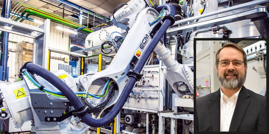
Evolving Efficiency: Advantages of Multi-Chamber Isolated Heat Vacuum Furnaces

Adapting to new processing demands puts traditional equipment to the test. Can single-chamber solutions keep up, or will applications require different equipment options for efficient processing? In today’s Technical Tuesday, Bryan Stern, product development manager at Gasbarre Thermal Processing Systems, addresses the advantages multi-chamber isolated heat vacuum furnaces bring to the floor.

This informative piece was first released in Heat Treat Today’s November 2024 Vacuum print edition.


Do You Hear That? It’s the Sound of Change . . .

In the evolving landscape of vacuum heat treatment, single-chamber batch furnaces have long been the cornerstone of material processing. However, with more traditional processes shifting to vacuum, rising energy costs, and increasing environmental pressure, the disadvantages of that approach are emphasized, enhancing the appeal of alternative technologies. Multi-chamber vacuum equipment, while not new to the industry, offers significant solutions to inefficiencies and challenges faced by single-chamber systems. With advances in technology, improved operational planning, and an increasingly competitive market, multi-chamber isolated heat furnaces are becoming a more viable choice.

What Is an Isolated Heat Vacuum Furnace?

An isolated heat vacuum furnace keeps the heat chamber separate from the ambient atmosphere throughout the process, including loading and unloading. This allows the heated zone to maintain a stable temperature and vacuum between cycles, unlike single-chamber furnaces, which must heat up and cool down for each new load. Key components of this furnace type include an additional evacuation chamber, a dynamic sealing door, and a mechanism for moving the workload between chambers. While multi-chamber isolated heat furnaces may be batch or continuous, the above features fundamentally distinguish them from single-chamber batch equipment. This difference is more than just a technical nuance; it has profound implications for operations and efficiency.

The widespread use of single-chamber vacuum furnaces has significantly shaped the design and operation of vacuum furnaces today. But it is important to remember some of the challenges to this approach that we often take for granted.

Energy Efficiency Has Entered the Chat

Single-Chamber Challenge

In single-chamber systems, the entire furnace must go through a full cycle of loading, evacuation, ramping, soaking, cooling, and unloading for every batch of parts. This adds significant “dead time” on either side of the thermal process. In addition to pump-down time, ramping from room temperature typically adds 1–2 hours to the cycle time before soaking which creates a barrier to throughput. Another drawback is that the energy required to heat the furnace is thrown away after every cycle. Due to the high thermal capacity of materials like graphite and molybdenum, this is not inconsequential. With 100% thermal efficiency defined as only consuming the energy required to heat the work and fixturing, single-chamber batch furnaces typically operate in a thermal efficiency range of around 30%–50%.

Isolated Heat Advantage

In an isolated heat furnace, the work zone remains at temperature and the energy required to heat the furnace is not thrown away. Additionally, the introduction of work to a preheated work zone allows the load to be heated more quickly, reducing the time required to achieve temperature and reducing holding losses. While multi-chamber batch furnaces experience some savings, they still consume excess energy since the heat cage is empty during unloading, loading, and evacuation. Continuous configurations, however, see significant improvement with only holding losses and the energy required to heat the work and fixturing being consumed. These advantages mean that continuous furnaces typically operate in a thermal efficiency range of 45%–65%. The result is a 15%–35% energy efficiency improvement over the majority of existing equipment.

Design Optimization: Do I Detect Some Tension?

Single-Chamber Challenge

The tension of designing a single-chamber furnace to handle both heating and cooling in the same space presents substantial challenges. Insulation pack thickness is often limited to balance the need for quick pump-down. Gas nozzle penetrations through the insulation pack create direct radiation losses. This erodes thermal efficiency, adds thermal mass, and restricts gas flow during cooling. These conflicting design priorities often lead to unsatisfactory compromises and fluctuating designs. Between the additional energy to heat and cool and increase power demand at temperature, there are a lot of energy savings being left on the table.

Isolated Heat Advantage

Because the heating and cooling take place in separate locations, multi-chamber isolated heat equipment benefits from the ability to have dedicated designs tailored at each work position. More insulation can be used as conditioning time is not a significant consideration. Additionally, the insulation can be designed without penetrations, further reducing losses. Moving the work to a dedicated cooling position removes restrictions to gas flow and allows the work to radiate directly to the cold wall. This is especially beneficial at the beginning of a quench when the work is at high temperature. This can allow cooling rates to be achieved with lower quench pressures and smaller quench motors.

Thermal Cycling: Here We Go Again . . .

Single-Chamber Challenge

A single-chamber furnace must be built to endure extreme thermal cycling again . . . and again. This requires detailed design consideration to account for thermal shock, expansion, ratcheting, creep, and low-grade oxidation — all of which contribute to maintenance and replacement cost for expensive, long lead refractory components.

Isolated Heat Advantage

Since the heated portion of the furnace remains at stable temperature and vacuum, internal components are not subject to the same destructive forces. An isolated heat cage can remain in service much longer before requiring service or replacement. It also decreases the likelihood of sudden and unexpected equipment failure. Increasing the lifespan of the most expensive consumable assembly in the furnace is an incredibly valuable advantage that is frequently overlooked.

rectangular promo of HTR, smiling bearded man, blue background, HTR banner
Find more on this topic in Heat Treat Radio episode #110. Bryan discusses the shift from single-chamber batch furnaces to isolated heat vacuum furnaces and speaks to some of the advantages mentioned in this article. Click the image to watch, listen, and learn on Heat Treat Radio.

Throughput and Load Size: Can They Help?

Single-Chamber Challenge

Single-chamber batch vacuum processing is notorious for the long cycle times and resulting limited throughput. One way to reduce the costs of the wasted energy and dead time is to increase the load size to distribute the cost over more work. While this can increase capacity and reduce the cost per part, it is counterproductive to many objectives of the heat treating process. As the load size increases, it becomes more difficult to maintain thermal and process uniformity across parts at the surface versus the center of the load. This is especially problematic for densely packed loads. Loads take longer to soak out to a uniform temperature, extending cycle times. Similarly, it is difficult to achieve rapid and uniform cooling rates which can lead to higher quench pressures, larger cooling motors, or underutilizing the work envelope.

Isolated Heat Advantage

While multi-chamber batch isolated heat furnaces experience many of the other advantages discussed in this article, throughput is where continuous configurations really shine. Because separate loads are being processed simultaneously, similar or greater throughputs can be achieved with much smaller load sizes. For instance, a process with a two-hour soak would typically require around a five-hour total cycle time in a single-chamber furnace. That same process could be segmented in a continuous furnace indexing loads in as little as 15 minutes, depending on the configuration of the equipment (see Figure 3). With a throughput ratio of 20:1, each load would only need to be 1/20th of the batch load to achieve the same throughput. With these mechanics, it quickly becomes apparent how continuous processing is capable of achieving much greater throughput while benefiting from the uniformity of smaller load sizes as well as the other advantages discussed.

Figure 3. Multi-chamber continuous gas-quench furnace
Source: Gasbarre Thermal Processing Systems

Scalability: And Another and Another . . .

Single-Chamber Challenge

Increasing the capacity of a single-chamber production line necessitates adding additional discrete furnaces. This means that all of the equipment systems are duplicated. Each furnace means another chamber, pumping system, manifolds, quench motor, VFD, control cabinet, certifications, instrument calibrations, etc. There really is no economy of scale available to help facilitate high volume production.

Isolated Heat Advantage

For most processes, increasing the capacity of a continuous multi-chamber furnace only requires adding additional heated work positions to shorten the index rate. All other auxiliary equipment and infrastructure can serve double-duty, and redundant systems and maintenance are avoided. This applies the cost directly to the necessary equipment (heat cage, elements, power supply, etc.). The resulting economy of scale often makes continuous equipment a far greater value proposition for high-volume applications that would otherwise require multiple furnaces.

Vacuum Performance: Don’t Reduce Me Like That!

Single-Chamber Challenge

Because single-chamber batch furnaces are exposed to air and humidity between each cycle, they require a higher vacuum (i.e., lower pressure) to achieve the purity required for a given process. This is because even though the furnace is evacuated to a low pressure, the remaining atmosphere is still primarily comprised of oxidizers in the form of residual air and water molecules desorbing from the internal surfaces of the furnace. Achieving the high vacuum levels required to achieve the necessary reducing atmosphere in a reasonable time can result in additional pumping equipment such as a booster or diffusion pump. This adds to system complexity, upfront cost, maintenance, and operating cost. Unfortunately, vacuum processes are often developed in, and organized around, single-chamber batch processing, so the actual purity requirement often gets distilled into an ultra-low vacuum level on the process specification. Consequently, these aggressive vacuum specifications are carried over to other types of equipment where they may not be necessary to achieve the same results.

Isolated Heat Advantage

Because the heat cage remains under vacuum throughout the process, there is less exposure to atmospheric contaminants. This allows oxidizing constituents to decay to very low levels leading to improved vacuum purity. Even though the absolute pressure is higher, the makeup of the remaining atmosphere is primarily inert. Given time for desorption to decay, it is entirely possible to have a purer environment at a higher pressure without requiring the complex pumping systems necessary in a single-chamber batch furnace. Reduction levels associated with diffusion pumping in single-chamber furnaces can be achieved at higher pressures with a two-stage or even single-stage pumping systems in an isolated heat furnace. This is one of the most overlooked and misunderstood advantages of isolated heat processing.

The Shift Toward Isolated Heat Furnaces

Despite the many challenges associated with single-chamber batch processing, the prevalence of these furnaces has remained high due to their simplicity and familiarity. So, why are multi-chamber furnaces gaining traction now?

“There is a pending perfect storm of market conditions poised to tip the scales.”

There is a pending perfect storm of market conditions poised to tip the scales. More and more traditional processes are shifting to vacuum for its long list of advantages, including tighter process control, flexibility, safety, insurance liability, and improved working environment, just to name a few. This push to convert more processes is driving a need to optimize efficiency and improve cost. The existing approach has known intrinsic inefficiencies and a limited growth path for improvement.

As more heat treaters either experience or compete with the benefits of multi-chamber isolated heat equipment, adoption will continue to accelerate.

Challenges and Considerations

While isolated heat furnaces offer numerous advantages, they are not without challenges. These systems are more complex, require a detailed specification process, and may not be suitable for very large components, intermittent operations, or applications requiring a high degree of flexibility. Many of the advantages of multi-chamber equipment show up in operating and maintenance costs. These benefits can be missed if these costs are not properly accounted for in the ROI analysis phase. Overemphasizing upfront costs can mean missing out on a much better return on investment for equipment with installation life in the range of 20–30 years.

Applications and Future Prospects

Isolated heat vacuum furnaces are not industry specific; rather, they offer advantages across a wide range of applications. Processes characterized by short cycle times benefit because a greater percentage of the floor-to-floor time is dead time and can be recovered, improving equipment utilization. Processes characterized by long cycle times benefit because they can be segmented and indexed at much faster rates, increasing throughput. Surface treatments can benefit from the process uniformity of smaller load sizes without sacrificing throughput. High-volume production environments, in particular, stand to gain the most. Whenever there is a need for more than one batch furnace or where there are numerous small parts in a large work zone, the efficiency and cost savings of continuous isolated heat furnaces truly stand out.

Conclusion

The industry’s focus on efficiency, reduced emissions, and lower operating costs makes isolated heat vacuum furnaces a promising direction for the future. While single-chamber furnaces will still have their place, isolated heat furnaces are becoming more prevalent for many heat treatment processes. Offering superior energy efficiency, better process control, and a more sustainable approach to thermal processing, these furnaces will enable manufacturers to provide high quality, cost-effective solutions that meet today’s market demands and future challenges.

About the Author:

Bryan Stern
Product Development Manager
Gasbarre Thermal Processing Systems

Bryan Stern has been involved in the development of vacuum furnace systems for the past eight years and is passionate about technical education and bringing value to the end-user. Currently product development manager at Gasbarre Thermal Processing Systems, Bryan holds a B.S. in Mechanical Engineering from Georgia Institute of Technology and a B.A. in Natural Science from Covenant College. In addition to being a member of ASM, ASME, and a former committee member for NFPA, Bryan is a graduate of the MTI YES program and recognized in Heat Treat Today’s 40 Under 40 Class of 2020.

For more information: Contact Bryan at bstern@gasbarre.com. 


Evolving Efficiency: Advantages of Multi-Chamber Isolated Heat Vacuum Furnaces Read More »