“Plan, do, check, act.” When it comes to caring about carbon footprint, a path forward to may seem too out-of-reach. But breaking down process heating and how to efficiently consider carbon use can be possible with industry resources.
This Sustainability Insight article was composed by Michael Stowe, PE, the senior Energy Engineer at Advanced Energy for Heat Treat Today'sSeptember 2023 People of Heat Treatingprint edition.
Michael Stowe, PE
Senior Energy Engineer
Advanced Energy
Source: IHEA
Over the past several years, process heating energy markets have shifted in response to significant global pressures. The need to understand the impact of greenhouse gases (GHGs), especially carbon based emissions, on climate change is gaining more interest from organizations that have industrial process heating. Organizations that manufacture or use process heating equipment need to understand the impact their equipment can have on carbon emissions. The terms “carbon emissions” or “carbon footprints” use the word “carbon,” but these terms can include other GHGs, and the carbon refers to carbon dioxide gas (CO2).
Process heating requires energy input. The energy sources for process heating most frequently include the combustion of carbon-based fossil fuels such as natural gas, propane, fuel oil, diesel, or coal. Also, most combustion processes have a component of electricity to operate combustion air supply blowers, exhaust blowers, circulation fans, conveyors, and other items. Figure 1 shows the chemical process for the combustion of methane (i.e., natural gas).
Figure 1 demonstrates that during combustion, methane (CH4) combines with oxygen (O2) to form carbon dioxide (CO2) and water (H2O). This same process is true for any carbon-based fuel. If you try to imagine all the combustion in progress across the globe at any given time, and knowing that all this combustion is releasing CO2, then it is easy to see the problem and the need for CO2 emission reduction.
Figure 1. Chemical process for methane combustion
(Source: Advanced Energy)
In basic terms, if you have a combustion process on your site, then you are emitting CO2. The electricity consumed to support the combustion processes also has a carbon component and the consumption of this electricity contributes to a site’s carbon footprint. Climate change impacts due to these carbon emissions have prompted government and corporate actions that are creating unique new opportunities for more sustainable and lower carbon process heating methods.
So, combustion and electricity consumption on your site contribute to your carbon footprint. Knowing this, organizations may now want to understand the actual level of their carbon footprint and ways to reduce it. There are many methods and resources available to help organizations understand and work to improve their carbon footprint.
The Industrial Heating Equipment Association (IHEA) has recognized this need to understand carbon footprints and is in the middle of a four-part webinar series on this topic. Session three (held on July 20, 2023) covered methods and resources to help organizations determine and improve their carbon footprint.
Session 3: DOE Tools and Programs for GHG Reduction
There are many options available to help determine carbon emissions for equipment, processes, sites, and organizations. This presentation will review some of these available tools and how to apply them to different situations. Carbon emissions are directly tied to energy consumption, so it is very important to understand how all your energy is consumed on site by energy type. This presentation will provide tools and programs to help you understand your energy consumption and thereby understand your carbon emissions. Additionally, energy improvement projects are also carbon emission reduction projects. This session will help you understand how to determine the impact of energy projects on your carbon footprint.
Session 4: Ongoing Sustainability — Industry Best Practices for Continual Improvement
Carbon reduction is not a project, it is a process, and must be ongoing. Earlier sessions will help you determine your carbon footprint and understand ways to track and improve your carbon footprint. In this presentation, we will review methods and programs to ensure the continual improvement of your carbon reduction efforts. Following the “plan, do, check, act” method used in many continual improvement programs, we will review steps to take for keeping your momentum moving in the right direction. We will also plan to have industry case studies for success in ongoing and improving carbon reduction programs.
Registration for these sessions can be found on the events page of www.ihea.org. If you or your organization want to learn more about your carbon footprint and how to measure and reduce it, you will not want to miss this opportunity.
In summary, heat treating, and other process heating methods, require significant energy, much of which is fueled with carbon-based fossil fuels, and associated with support electricity consumption. Both combustion and electricity consumption contribute to an organization’s carbon footprint. One of the best ways to help manage your carbon footprint is to understand and manage your energy consumption. For more information on this topic, please check out the IHEA Sustainability & Decarbonization Initiatives.
About the author:
Michael Stowe (PE) is the senior energy engineer at Advanced Energy. Michael focuses on process heating and energy efficiency in manufacturing plants. He has significant experience in the manufacturing industry serving in various roles as design engineer, production manager, plant engineer, and facilities engineer over the past 27 years.
Find heat treating products and services when you search on Heat TreatBuyers Guide.com
When it comes to optimizing the working life and overall performance of heat treatment alloy castings, proper alloy selection and design based on the intended application is a critical starting point. Discover the variables behind alloy selection and design and the additional factors that contribute: furnace maintenance, casting inspection, and cost reduction strategies.
This Technical Tuesday article was composed by Matthew Fischer, manager of Technical Sales, Castalloy Group for Heat Treat Today'sAugust 2023 Automotive Heat Treating print edition.
Alloy Selection and Design Criteria
Matthew Fischer
Manager of Technical Sales for Heat Resistant Products
Castalloy Group NA
Source: Castalloy Group
Optimal design and alloy composition for any heat treatment casting always requires careful consideration of a number of key operating variables. This is the only way to guarantee the part will deliver maximum utilization and efficiency for the intended application.
These variables include:
Anticipated service and maximum operating temperature
Size, orientation, and weight of the load
Thermal cycling and/or quenching
Range of temperature cycling
Frequency of temperature cycling
Rate of change of temperature
Type of atmosphere or other corrosive conditions of the application
Type of quenching or cooling
Size, shape, and weight of part(s)
How are the parts loaded and oriented? (e.g., manually, robotically, individually, bulk)
How is the alloy supported in the equipment? (e.g., rails, hearth, rollers, piers)
In addition, there are fundamental factors that heavily influence optimal component design and alloy composition. For instance, the type of furnace used (e.g., box, pit, integral quench, continuous), alloy handling mechanism (fixture and tray), and application process (e.g., carburizing, normalizing, annealing, austempering, vacuum heat treating) all have an important role to play. It is worth noting, however, that the decision-making process is a fine balancing act that isn’t necessarily evenly weighted. While a specific alloy composition may Fiaddress the majority of performance needs, it may hinder others. Prioritizing end-use performance traits is therefore essential.
Furnace and Process Environment Maintenance
Figure 1. Cast tray and fixtures
Source: Castalloy Group
How furnaces and processes are performance monitored and maintained is also key when seeking to optimize the performance and lifespan of heat treatment alloy castings. The specific type of furnace will dictate exact equipment and process maintenance requirements, but there are several universal best practice procedures and guidance processes that should be followed.
For instance, the Automotive Industry Action Group (AIAG) has established CQI-9 (Continuous Quality Improvement) standards for heat treatment. These standards provide the guidelines for a continuous cycle of assessment, planning, and improvement with respect to heat treat processing and due care of handling customer parts. The CQI-9 standards direct the heat treater to have and maintain the necessary equipment and associated control instruments used to monitor and record the furnace process operating parameters. They also promote the proper furnace operating process environment. However, the standards do not comprehensively address the overall maintenance requirements of the furnace and process environment equipment. Generally, yearly scheduled maintenance is important to the long-term successful continuous operation of furnace equipment. Lack of or intermittent maintenance can lead to unplanned shutdowns. Here are some of the most common maintenance issues to monitor and remedy:
Example 1: Support Misalignment
If base tray support mechanisms are in alignment (in the direction of travel) and flat (level throughout) to provide proper support of the base tray and associated fixtures and parts, then the tray should move through the furnace equipment without issue, provided the tray is in good operating condition. However, if there are broken rails or piers — or broken/deformed roller rails or wheels — then over time the tray may exhibit wear, deformation, cracks, or breaks.
Example 2: Transfer Mechanism Misalignment
If the transfer mechanisms are square to the tray (in the direction of travel) and level throughout, providing proper contact with the base tray, then the tray should move through the furnace equipment without issues, provided the tray is in good operating condition. However, if there are misaligned transfer mechanisms (pusher rods, pusher head, handler head etc.), then over time the tray may exhibit associated wear, deformation, distortion, cracks, or breaks.
Figure 2. Flat level surface and tray/grid
Source: Castalloy Group
Example 3: Uneven Heating
Although the furnace may be able to maintain an average furnace temperature as measured by a single control thermocouple, there may be uneven heating conditions (side-to-side, top-to-bottom, front-to back) due to a variety of factors, which could result in uneven thermal cycling of the alloy castings. This potential non-uniform heating of the alloy could lead to deformation, cracks, or breaks of the alloy castings. The CQI-9 standards work to monitor and address non-uniform heating using a periodic temperature uniformity survey (TUS) of the furnace heating chamber.
Figure 3. Example of original supplied alloy casting for comparison.
Source: Castalloy Group
Example 4: Non-Uniform Cooling
Although the quench chamber may be able to maintain an average quench medium temperature as measured by a control thermocouple, there may be uneven cooling conditions within a load due to a variety of factors, which could result in uneven thermal cycling of the alloy castings. If left unchecked, any of these issues may result in unintended wear, deformation, distortion, cracks, or breaks of the alloy castings. Furnace material handling issues may also result in an unplanned equipment downtime and productivity loss.
Alloy Castings Inspection
Alloy castings (fixtures, trays, grids) should be inspected periodically to ensure they are in adequate working order. This inspection could be performed when the furnace equipment is taken out of operation for summer or winter maintenance inspections and shutdowns. The main areas to consider are flatness, squareness, and proper proportion.
Damaged component
Source: Castalloy Group
Flatness
Trays, grids, and fixtures should remain flat or level across the width and length. Sagging, bowing, warping, or twisting can cause material handling issues within furnaces and associated process equipment. A simple method to check the flatness is to have a table with a flat and level surface where the tray, grid, or fixture may be placed to check and observe the flatness of the alloy casting. An alternate method to check the alloy casting flatness would be to use a level across the casting to check flatness.
Squareness
Trays, grids, and fixtures should remain square across the width and length. Being out of square can cause material handling issues within furnaces and associated process equipment. A simple method to check the squareness is to have carpenter’s square tool where the tray, grid, or fixture may be examined to observe the squareness of the alloy casting.
If the tray used in the heat treatment equipment is an assembly of trays, then each tray should be examined for squareness in all four corners. Trays that are out of square may cause tracking problems in the material handling of the furnace, or associated equipment, and should be replaced.
Figure 4. Square tool and tray/grid
Source: Castalloy Group
Proper Proportion
Trays, grids, and fixtures should remain in proper proportion as originally designed. Having bulges or large breaks that are outside of the alloy dimensional alignment compared with the originally supplied alloy casting can cause material handling issues within furnaces and associated equipment. A simple method to check the dimensional proportion is to have a picture or drawing of the originally supplied alloy casting. The tray, grid, or fixture can be compared with this in order to observe the overall soundness of the alloy casting. Suspect castings should be removed from daily operation to prevent potential material handling and associated equipment maintenance issues. An alternative to visual inspection is to make a simple jig that can be used to confirm the dimensional integrity of the alloy casting. Observable patterns of proportional changes within a common area of the alloy castings may indicate a potential issue occurring within the heat treat equipment that should be monitored and investigated before it becomes a major equipment issue and causes an unplanned equipment shutdown.
Optimizing Alloy Castings Using Periodic Purchases
Figure 5. Jig tool to check proportion
Source: Castalloy Group
Periodic purchases of alloy castings should be planned and budgeted annually to maximize casting working life, to minimize process interruptions due to potentially expired useful life of alloy castings, and to manage future expenditures for replacement alloy casting purchases.
In general, budgeting for a percentage of alloy purchases over a two to three- year period, depending on current and planned future operations, would be supportive of continuous production operations. The periodic alloy purchase is then integrated into the existing production operations and suspect alloy castings, if any, can be removed from daily production operations.
There are multiple approaches that can be implemented and adjusted according to individual plant production needs:
One approach to consider is the purchase of one-third of the total alloy purchase per year over the following three years after an initial purchase. In a continuous daily production operation, the initial purchased quantity of alloy castings will have been replaced, if needed, over the elapsed time.
An alternate approach to consider is a staggered percentage over three years. For example, 20–25% replacement the first year; 30–35% replacement the second year; 35–40% replacement the third year, adjusted as necessary based on current operating and business conditions.
This approach would also be useful for ramping up alloy quantity needs to meet increasing demand over time and could be an opportunity to address potential delivery time requirements with coordinated planned periodic purchases.
Additionally, intermixing newly purchased alloy castings along with production alloy castings, may provide for extended life for the latter.
Scrap Alloy Recycling: New Alloy Purchase Credit for Returning Your Scrap Alloy Material
When alloy castings are no longer usable in daily heat treatment operations, it can be advantageous to sell them back as scrap to the alloy supplier. The supplier should be able to provide a scrap repurchase credit that can be used for future purchases of new alloy castings.
Figure 6. Visual demonstration of capital flow for initial and subsequent alloy purchases
Source: Castalloy Group
Generally, this scrap alloy repurchase credit may be used in whole or in part as directed by the customer for new replacement alloy casting purchases.
As well as being cost-efficient, scrap alloy castings recycling supports the long-term sustainable use of metals, minimizes the potential negative impact on the earth’s environment, and reduces the overall carbon footprint of both alloy user and supplier.
Summary
Figure 7. Typical scrap alloy trays and grids Source: Castalloy Group
To review, improving the working life of heat treating cast alloys starts with design and is maintained with factors that account for the full alloy casting life:
Choosing the right design and alloy composition for heat treatment castings is fundamental to optimizing their working longevity and performance. This decision can only be made by carefully considering key aspects of the intended casting
Maintaining furnace equipment and process environment operating conditions will also assist in maximizing the working life and overall performance of the alloy castings.
Alloy casting inspection will support heat treat operations and minimize potential equipment downtime by providing evidence of furnace equipment issues or malfunction.
Periodic budgeted alloy casting purchases support heat treat operations, will help maximize uptime, and minimize potential downtime associated with suspect or failing alloy castings.
Scrap (expired useful life) alloy repurchases can be used to off set the costs associated with new alloy casting purchases. Scrap alloy recycling also minimizes negative impact on the environment.
About the Author:
Matthew Fischer is the manager of Technical Sales for Heat Resistant Products at Castalloy Group NA. He has thirty years of experience in furnace design and applications working for a leading heat treat furnace equipment supplier. Additionally, he has worked for several years as a senior heat treat manufacturing engineer for a global tier-1 automotive company as well as in the controls and instrumentation fields across multiple industries, including thermal processing and heat treating.
Vacuum furnaces are widely used in the aerospace and automotive industries. These furnaces are used for multiple processes including brazing, aging, and solution heat treating for countless materials. Typically, vacuum furnaces are utilized to ensure a lack of oxidation/contamination during heat treatment. This article will talk about the origins, theory, and main parts of vacuum technology and how it is used in both aerospace and automotive industries.
This Technical Tuesday feature was written by Jason Schulze, director of technical services at Conrad Kacsik Instrument Systems, Inc., and was first published in Heat Treat Today's December 2022 print edition.
A Brief History
Vacuum furnaces began to be used in the 1930s for annealing and melting titanium sponge materials. Early vacuum furnaces were hot wall vacuum furnaces, not cold wall vacuum furnaces like we use today. Additionally, most early vacuum furnaces did not utilize diffusion pumps.
Vacuum Heat Treat Theory
Vacuum technology includes vacuum pumping systems which enable the vessel to be pulled down to different stages through the process. Degrees of vacuum level are expressed opposite of pressure levels: high vacuum means low pressure. In common usage, the levels shown below in Figure 1 correspond to the recommendations of the American Vacuum Society Standards Committee.
Vacuum level will modify vapor pressure in a given material. The vapor pressure of a material is that pressure exerted at a given temperature when a material is in equilibrium with its own vapor. Vapor pressure is a function of both the material and the temperature. Chromium, at 760 torr, has a vapor pressure of ~4,031°F. At 10¯5, the vapor pressure is ~2,201°F. This may cause potential process challenges when processing certain materials in the furnace. As an example, consider a 4-point temperature uniformity survey processed at 1000°F, 1500°F, 1800°F, and 2250°F. This type of TUS will typically take 6-8 hours and, as the furnace heats up through the test temperatures, vacuum readings will most likely increase to a greater vacuum level. If expendable Type K thermocouples are used, there is a fair chance that, at high readings, you may begin to have test thermocouple failure due to vapor pressure.
Figure 1. Vacuum levels corresponding to the recommendations of the American Vacuum Society Standards Committee
Source: Jason Schulze, Conrad Kacsik Instrument Systems, Inc.
Vacuum Furnace Pumping System
Vacuum heat treating is designed to eliminate contact between the product being heat treated and oxidizing elements. This is achieved through the elimination of an atmosphere as the vacuum pumps engage and pulls a vacuum on the vessel. Vacuum furnaces have several stages to the pumping system that must work in sequence to achieve the desired vacuum level. In this section we will examine those states as well as potential troubleshooting methods to identify when one or more of those stages contributes to failure in the system.
Vacuum furnaces have several stages to the pumping system that must work in sequence to achieve the desired vacuum level. Each pump within the system has the capability to pull different vacuum levels. These pumps work in conjunction with each other (see Figure 2).
Figure 2. Vacuum pumps work in conjunction with one another
Source: Jason Schulze, Conrad Kacsik Instrument Systems, Inc.
The mechanical pump is the initial stage of vacuum. This pump may pull from 105 to 10. At pressures below 20 torr the efficiency of a mechanical pump begins to decline. This is when the booster pump is initiated.
The booster pump has two double-lobe impellers mounted on parallel shafts which rotate in opposite directions (see Figure 3).
Figure 3. Booster pump positions
Source: Jason Schulze, Conrad Kacsik Instrument Systems, Inc.
The diffusion pump (Figure 4) is activated into the pumping system between 10 and 1 microns. The diffusion pump allows the system to pump down to high vacuum and lower. The diffusion pump has no moving parts.
Figure 4. Diffusion Pump
Source: Jason Schulze, Conrad Kacsik Instrument Systems, Inc.
The pump works based on the vaporization of the oil, condensation as it falls, and the trapping and extraction of gas molecules through the pumping system.
Image 1. Holding Pump
Source: Jason Schulze, Conrad Kacsik Instrument Systems, Inc.
The holding pump (Image 1) creates greater pressure within the fore-line to ensure that, when the crossover valve between the mechanical and diffusion pump is activated, the oil within the diffusion pump will not escape into the vessel.
Vacuum Furnace Hot Zone Design
Image 2. Insulated
Source: Jason Schulze, Conrad Kacsik Instrument Systems, Inc.Image 3. Radiation
Source: Jason Schulze, Conrad Kacsik Instrument Systems, Inc.
The hot zone within a vacuum furnace is where the heating takes place. The hot zone is simply an insulated chamber that is suspended away from the inner cold wall. Vacuum itself is a good insulator so the space between the cold wall and hot zone ensures the flow of heat from the inside to the outside of the furnace can be reduced. There are two types of vacuum furnace hot zones used: insulated (Image 2) and radiation style (Image 3).
The two most common heat shielding materials are molybdenum and graphite. Both have advantages and disadvantages. Below is a comparison (Tables 1 and 2).
Table 1
Source: Jason Schulze, Conrad Kacsik Instrument Systems, Inc.Table 2
Source: Jason Schulze, Conrad Kacsik Instrument Systems, Inc.
Vacuum Furnace Quenching System
Quenching is defined as the rapid cooling of a metal to obtain desired properties. Different alloys may require different quenching rates to achieve the properties required. Vacuum furnaces use inert gas to quench when quenching is required. As the gas passes over the load, it absorbs the heat which then exits the chamber and travels through quenching piping which cools the gas. The cooled gas is then drawn back into the chamber to repeat the process (see Figure 5).
Figure 5.Diagram of gas quenching
Source: Jason Schulze, Conrad Kacsik Instrument Systems, Inc.
Vacuum Furnace Trouble Shooting
In Table 3 are some helpful suggestions with regard to problems processors may have.
Table 3
Source: Jason Schulze, Conrad Kacsik Instrument Systems, Inc.
Summary
Vacuum furnaces are an essential piece of equipment when materials need to be kept free of contamination. However, there are times when this equipment may not be necessary, and is therefore considered cost prohibitive, although this is something each processor must research. This article is meant to merely touch on vacuum technology and its uses. For additional and more in-depth information regarding vacuum furnaces, I recommend a technical book called Steel Heat Treatment, edited by George E. Totten.
About the Author: Jason Schulze is the director of technical services at Conrad Kacsik Instrument Systems, Inc. As a metallurgical engineer with over 20 years in aerospace, he assists potential and existing Nadcap suppliers in conformance as well as metallurgical consulting. He is contracted by eQuaLearn to teach multiple PRI courses, including pyrometry, RCCA, and Checklists Review for heat treat.
We get it. You read all day: emails, memos, furnace monitoring screens. To give your eyes a break, Heat TreatTodaywanted to provide some grab and go visual resources. In this original content piece, check out some visuals to help you learn about the difference between Nitriding and FNC; discover how the U.S. is doing in the race to green steel production; and get an example of the type of numbers that are normal for a CQI-9 probe method A test.
In Heat TreatToday's August 2021 Automotive print edition, Lourenco Goncalves, chairman, president, and CEO of Cleveland-Cliffs, Inc. made a big statement: "The United States is the benchmark of the world in all things steel. Amongst all major steelmaking nations, we have by far the greenest emissions profile."
In a climate where the United States often gets a bad rap when it comes to environmental concerns, Lourenco's statement is hard to believe. But, the data below contradicts this bad reputation. Check out the graphic below to learn how the United States stacks up to other countries in steel production.
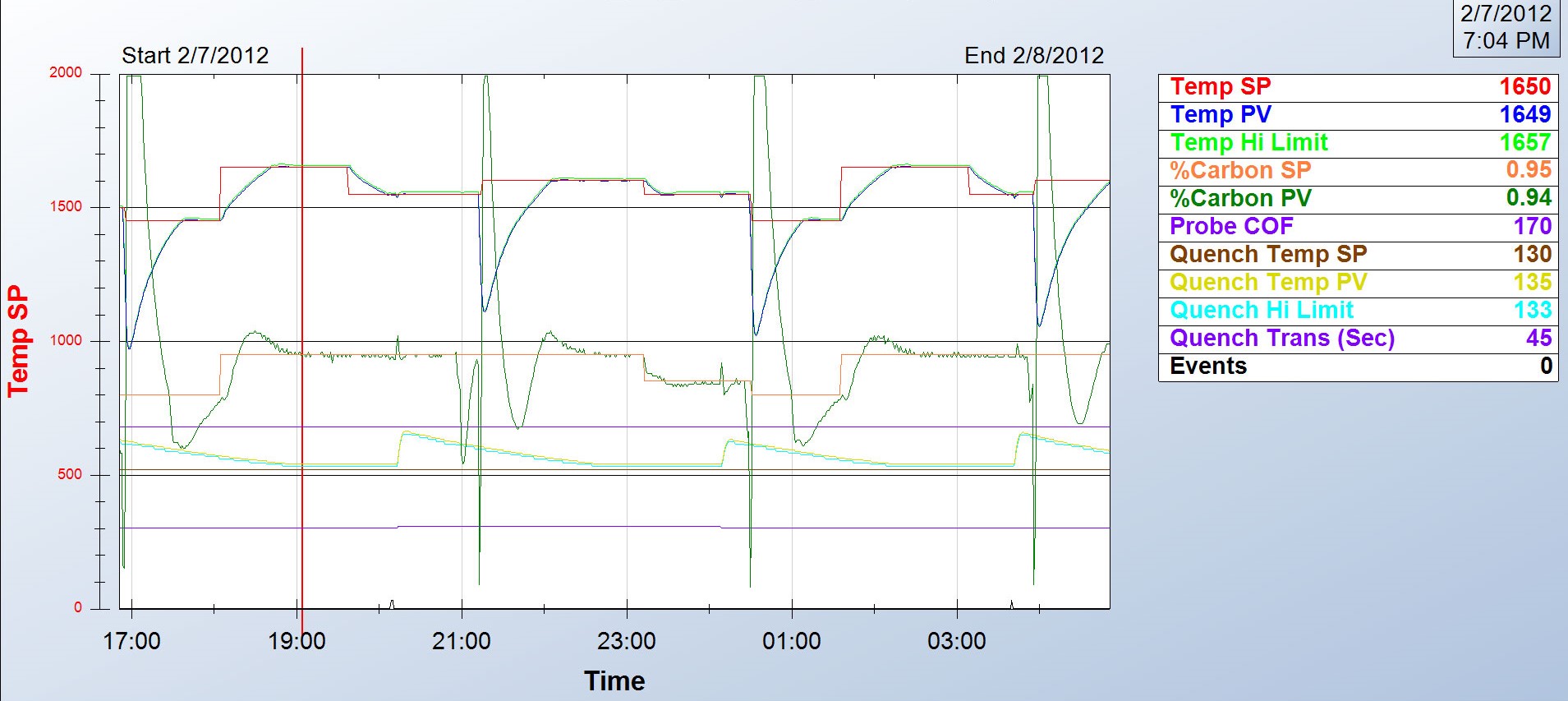
Ensuring heat treating equipment falls within CQI-9 standards can be tricky. According to Erika Zarazúa, regional purchasing manager at Global Thermal Solutions, probe method A may be the best way to identify variations in control systems.
If you're curious about how probe method A works, view the chart below (in both English and Spanish) for an example of the kind of numbers that are typical for this test method.
Table 1. Probe method A Tabla 1. Método de sonda A
These days, it seems like most heat treat shops are updating equipment or changing procedures to accommodate demands for ferritic nitrocarburizing. But how different are the two processes, really? When it comes to materials commonly processed, time cycles involved, and atmospheres required, where does the difference between nitriding and FNC begin? The chart below is a quick and easy guide to distinguishing the difference between these two hardening processes. Skim away or take a deep dive into the technicalities!
Erika Zarazúa, a 40 Under 40 Class of 2021 member, is a metallurgical engineer with over 18 years of experience in heat treatment operations and temperature measurement and has worked in multiple engineering, quality, and project roles in the automotive and aerospace industries. Erika currently holds the position of regional purchasing manager at Global Thermal Solutions.
Heat TreatToday publisher Doug Glenn wraps up this three-part series with Pelican Wire experts by talking with John Niggle from Pelican Wire about thermocouple insulation types and considerations.
The first two episodes cover the history, types, vocabulary, standards, and other basics of understanding how thermocouples work. Listen to the previous episodes of the series here.
Below, you can either listen to the podcast by clicking on the audio play button, or you can read an edited transcript.
The following transcript has been edited for your reading enjoyment.
Doug Glenn (DG): Welcome to Heat TreatRadio!
John Niggle (JN): Yes, it's good to see you again, Doug. I know we've run into each other a couple of times out there in the field. I'm looking forward to having the opportunity to do all of this stuff in person again.
DG: It will be nice. Before we hit the record button, we were talking about shows this fall and hoping that they happen because you, like I, are ready to get out and go.
You are the business development manager for Pelican Wire. If you don't mind, give us just a little bit of background about you and about your experience in the whole thermocouple world.
Pelican Wire headquarters
JN: Sure, absolutely. As you said, I am the business development manager at Pelican Wire. I've been at Pelican since 2013 so we're working out my eighth year here. I'm a career industrial sales representative. I do have previous experience also, actually, in the process instrumentation industry. Way back when, before I even knew how to spell thermocouples, I was selling that stuff when I first got out of college. My career has, sort of, gone full circle, let's say.
DG: Very nice. Well, you've got plenty of years of experience, which is great. We've had two previous episodes with your colleague, Ed Valykeo, and we covered a good bit of stuff. We covered a lot of basics in the first episode. We covered standardization, and things of that sort, in the second episode. I want to encourage any listeners who haven't listened to those episodes, feel free to go back, Google “Heat TreatRadio” and search for “Pelican Wire” and listen to episodes 1 and 2.
John, you and I want to move forward. I'm always kind of curious about this question: From your perspective, with your experience, why do we use thermocouples? Let's talk about what they are and why we use them.
JN: First of all, we have to assume that somebody is trying to measure the temperature of some sort of a process- a process or an event of some kind. That's basically what they're trying to do. Compared to other devices like RTDs, bimetal thermometers, liquid expansion state change devices and so forth, thermocouples are robust, they're inexpensive; they're repeatability, they're ease of use and size -- all of those factors lead them to be more widely used than another sort of thermal measurement device of any kind. It is the preferred method.
On top of that, I mentioned the expense part. Because they're relatively inexpensive, there are certain industries, the heat treat industry and smelting industry, for example, consider these as, actually, consumable or disposable. So, the cost factors in significantly in the industry that we're talking about here.
DG: I live in western Pennsylvania and the town where my wife grew up, there was an old Leeds and Northrup manufacturing plant. I believe they made the consumable thermocouples for melt shops. You would, basically, throw the thermocouple in and it would melt quickly but it would give you a response during that time.
CLICK to Listen!
JN: Right. And, as I mentioned earlier, the response factor is important, or that's one of the factors considered, when people are looking at thermocouple wire. And, you're correct, Ed Valykeo, as you mentioned, has 40 years of experience in the industry and has seen exactly the same sort of thing that you're talking about where people will just tack weld it onto something that gets thrown into a furnace or it gets thrown into a melting pot or something like that, and they're looking for that instantaneous temperature.
If you don't mind, I'll tell you that we've done some work, actually, in the aerospace industry and we had a customer that we sold significant, literally miles, of thermocouple wire to (when I say aerospace, it was specifically for space exploration) and this was because of whatever we had done with the insulation. I can't tell you, because it was before my time, but this is what was relayed to me- they were able to get another 3 - 4 seconds of temperature measurement out of that wire. That critical, extra data for them made all the difference in the world.
DG: We're going to get to the insulation part which should be interesting. You won't have to tell us any trade secrets, but we are headed in that direction anyhow.
So, different types of thermocouples. Again, just a review question for us. Why use them? Why the different types and why are we using different types?
JN: Forgive me, Doug, and the rest of the audience, for that matter, if I end of repeating some of the things that came out in the previous episode. Basically, when you're talking about thermocouples, there are the two chemistries; for lack of a better term, you have “base” and “noble” metals. The base metals are really the metals that we focus on at Pelican. The noble metals are the more expensive ones- rare earth metals, tungsten, titanium, platinum and all those sorts of things that people spend exorbitant amounts of money on. There are purposes for those, but, typically, what you're going to see in the heat treat industry, in particular, you're going to see a lot of the base metals.
I like to say that, truly, the 20 gauge K, in particular, is the 800 pound gorilla in the room. It's almost considered, and I think it would be by people in the industry, a commodity. There are untold miles of that wire that are used in the heat treating and smelting industry. K is used, really, because of the temperature range. It fits in well with what people do in the heat treating industry. It is good for temperatures from zero up to around 1260 C. It's inexpensive, it covers the ranges that those people are looking for, and, again, it's the 800 pound gorilla in the room when it comes to temperature measurement in the heat treating industry.
Click to read the Heat Treat Today Original Content article on thermocouples.
The other types such as J comes up periodically, particularly if you're looking at lower temperature ranges. You won't see it quite as often in the heat treating industry. You will see it somewhat, but not to the degree that you would K. The J thermocouple wire has an iron leg so it does oxidize and you need to be careful about that sort of thing. Type T thermocouple wire has a narrower range. It has very good response times in cryogenic and cold temperature applications. The higher, upper end of type T thermocouple wire, typically, wouldn't be of terrible interest to the audience that we're involved with here, for the most part, because the upper ends around 370 to 400 C degrees, in lab environments; that's where it's going to be the most popular.
There is also type E. It's a higher temperature, as well. Response time. Broader range is a little bit better than K at lower temperature ranges. An interesting one is type N that you will see fairly often in the heat treating industry. For those people not familiar with type N, it is different alloys than type K. It covers virtually the same temperature range that type K does and will, actually, have less drift than type K. It is more expensive because of the alloys that it is made of, but, again, if you're interested in less drift, then type N is worth looking at. It hasn't quite caught on in the US the way it has in, say, Europe, in particular, and that really has to do with the infrastructure of the instrumentation. People have instrumentation that is either calibrated for K or J or something like that. Now, there is instrumentation out there, now, that would use K and N both, so we may see more, particularly, in the aerospace industry I would think it would become more and more popular.
DG: That's helpful. It's always good to hear those things over again.
How about the parameters and/or the factors that need to be considered when you're constructing the wire to start with? What do we need to be worried about in that area?
JN: I don't know if I like the word “worried” exactly, Doug. It's more, what do we need to think about? What do we need to be concerned about? Besides the metallurgy that we just talked about, we need to think in terms of what the sensor is actually going to look like. Is it just the wire? Thermocouple wire, by itself, can be a thermocouple; that's it, without any protection or anything like that.
As I mentioned earlier, you can tack weld it to an ingot, or something like that, and there you go. You don't have any probe, there is no thermal well to protect it or anything like that. But, what we do need to think about, then, is the process that it's going to be involved in. Where is it going to be used? Is it going to see an environment where there is a flow. Is it going to see an environment where somehow the thermocouple wire can become damaged? In that case, then, we're headed in the direction of talking about what our customers are interested in. And for a customer for Pelican Wire, we're mainly talking about people who actually assemble thermocouples – they make the connections, they have the molds and all that sort of thing.
To be clear, Pelican Wire just makes wire. And, again, the thermocouple wire can be used as a thermocouple, but a tremendous amount of wire is actually connected to some sort of a sensor or a probe, as I said, and is protected in a thermal well or something along those lines.
"But, what we do need to think about, then, is the process that it's going to be involved in. Where is it going to be used? Is it going to see an environment where there is a flow. Is it going to see an environment where somehow the thermocouple wire can become damaged? In that case, then, we're headed in the direction of talking about what our customers are interested in."
John Niggle
DG: Do we also have to be concerned with oxidizing, carburizing atmospheres, corrosive atmospheres? Is that, also, something that we need to be aware of?
JN: Absolutely. And that is one of the reasons you will see a probe thermocouple is because the wire is protected from that atmosphere. Nearly all of the wires that we talked about would be affected, particularly, in say, like a sulfurous environment; it would be subject to corrosion, oxidation and something along those lines.
Other factors, of course, are the accuracy and how much space we have. Believe it or not, if it's going to go into a small orifice, then we need to think about what the age size is going to look like. And then the environment: Is it going to be abrasive? Is there movement? Is there some sort of braiding motion that could wear a hole in the wire in the insulation and so forth? There are a lot of things to think about.
DG: And, it would probably be a good idea, especially if our heat treat people are running anything outside of the norm, regardless of what it is, whether it be atmosphere, configuration, fixturing, if there is anything outside the norm, they would probably be wise to mention it to the thermocouple wire and/or thermocouple probe manufacturer and make sure that they know so that you guys can get help get the right thing on there in their furnace.
JN: Yes, absolutely. At the end of the day, we work with this every day. We have design engineers on staff who can assist with technical questions and so forth and, of course, our customers, and the actual thermal wire assembly people, this is what they do every day of the week.
“I'll tell you that we've done some work, actually, in the aerospace industry and we had a customer that we sold significant, literally miles, of thermocouple wire to (when I say aerospace, it was specifically for space exploration) and this was because of whatever we had done with the insulation.”
DG: Let's talk about something a little bit new, I guess, to our conversation here in this 3-part series, and that is the insulation that's going to go around these wires. Can you tell us what are the different types of insulations and what are the advantages and/or disadvantages of each, and why would we be using them?
JN: I'll break it down into, what I would call, the four basic categories. That would be an extruded insulation, insulations that are tapes, fiberglass insulations that are routinely worked with and then, of course, high temp textiles. High temp textiles, in particular, would be of interest to the audience here in the heat treat metallurgy world.
Extruded insulations can be a variety of thermoplastics. A term that, I think, Ed has probably mentioned before and we've talked about before is extension grade wire. That typically has a PVC insulation on it and the reason PVC works for that is that it's cheap and extension grade wire, typically, does not see the sorts of high temp environments that you're going to see in processes. It's really a signal wire that takes the signal from the probe or from the sensor to the process control device.
DG: So what kind of temperature tolerances can the extruded wire handle? Are we talking 300, 400 degrees? I guess you talk C, I talk F.
Teflon frying pan
JN: We talk whatever language our customer likes to talk, but we do talk C quite a bit. So, PVC is quite low, it's in the 200s F. But, when you're looking at fluoropolymer insulations (and Pelican is really a high temp house, so we focus on the higher temp insulations) you have FEP and PFA, those are in the 200s. PFA actually goes up to 260. So, you can see, it's probably not suitable for heat treating applications, smelting and that sort of thing. The advantages to those compounds would be that you're going to have abrasion resistance. Think about your Teflon frying pan: it's slick, it's smooth. So, if you're in an environment where there is some movement, it will be good for that. And, of course, it will have excellent moisture resistance and chemical resistance. Those would be the advantages to the extruded wire. The other advantage would be, because you'll have a thinner wall than you will with the other insulations, you'll have some more flexibility. So, if you have a type N radius, you can go around a corner easily.
The next step up, in terms of temperature resistance, would be the tapes. Basically, in that area, you're looking at PTFE tape, mica take and capped-on tape or polyamide tape. Those will give you slightly higher heat resistances. The mica, in particular, would give you more. (Mica, as a matter of fact, is used as a supplement to the PTFE to give it even higher heat resistance.) Mica will go up to 500 C, PTFE and the polyamides match, in terms of heat resistance, the extruder products around 260. What they do give you, again if you use the tapes, is the heat resistance you're looking for, some abrasion resistance and the moisture resistance. You'll have less flexibility because those products are stiffer, but they're also going to be a little bit lighter weight unless you incorporate the mica into it. Then, when you do that, you're going to end up with an even stiffer wire and it will be a little bit heavier, and all those will be larger in diameter than an extruded wire. If you look at an environment where you need to poke the wire through a hole and that hole is an eighth of an inch, you need to think really hard if what you're doing is going to work.
DG: So you've got extruded and you've got tapes.
JN: The next step after that would be fiberglass. In the case of fiberglass, you have E glass and S glass. Of the two, E glass would have the lower temperature resistance and you're looking at 482 C on the high end. For S glass, you're up to 704 C. Now you're starting to talk about insulations that you will see in the heat treat environment; it's quite common, especially on the S glass side where you're looking at the 704, you'll see a lot of people that need 500 C for whatever reason. The advantage, obviously, to the glass, as I mentioned, is the higher heat resistance.
There are disadvantages. Think about fiberglass for a minute. We actually have to saturate the wire to keep it from fraying without it ever really experiencing any abuse. If we don't saturate it, then the wire can fray, and you can get fiberglass in your fingers even, which is unpleasant. So, fiberglass has some disadvantages like that. If you put it in an environment where there is some movement, abrasion, vibration or something like that, it can be problematic. Also, it's going to be stiffer because it's saturated, typically. Sometimes you'll even see those saturants even cause problems in a heat treat environment where, if it gets too hot, the saturant can leave an ash behind. You're going to lose flexibility, as I said. You're not going to have the abrasion resistance, the chemical resistance or the moisture resistance that you're going to get from an extruded product.
The other one that we see, again, literally miles and miles and miles of, in the heat treat world would be what's called Refrosil and Nextel, (those are both, actually, trade names). We're talking about vitreous silica and ceramic. Again, those are, what we call, high temp textiles. Now, you're looking at products that are in the 1200 C range. Ceramic goes up to 1204, vitreous silica is in the 870's. Again, there are some of the same disadvantages with those that you're going to have with glass. It's going to be somewhat fragile. We don't saturate those because the saturants are not going to hold up in the environments that they're going to be placed into, so you would have that ash residue left.
Again, it will be stiff, it will be even larger in diameter than the fiberglass, which is larger than tape which is larger than the extruder products. Of course, you're not going to have the abrasion resistance, the moisture resistance or the chemical resistance. But it does protect the wire in those elevated temperature environments that are critical for the heat treating industry.
DG: Let's back up a bit. I want to understand something you said. You said, in the fiberglass, it is saturated and in the textiles it's not. I want to know what you mean by saturated.
JN: It's either a solvent-based or a water-based saturant that is applied to the wire to protect it. Think in terms of a varnish. It would be like a protective coating. Again, it just keeps the exterior of the wire, the bare wire, from being exposed. It's a coating, but we call it a saturant.
DG: High temperature textiles tend to be the stuff we're using, in the heat treat industry, probably most.
JN: Yes. Again, when I mentioned the 800 pound gorilla in the room, the 20-gauge K with the vitreous silica or the Refrosil would be an extremely popular product in the heat treating industry, absolutely.
DG: Let me ask you a very, very fundamental question. I'm curious of your answer to this. Why do we insulate wires at all? Is it done to protect from temperature or is it done simply to protect them from crossing with each other and grounding or shorting out? Why do we insulate?
"I'll go back to something that I know Ed talked about: the Seebeck effect. You have this loop; if you don't have that loop, then you don't have anything. You don't have the EMF, the electromotive force, that you're looking for."
John Niggle
JN: It is the second part. When you look at any wire construction, the two singles have to be insulated from each other. I'll go back to something that I know Ed talked about: the Seebeck effect. You have this loop; if you don't have that loop, then you don't have anything. You don't have the EMF, the electromotive force, that you're looking for. We do make a wire that is not duplex, but, typically, what you're going to see is a wire that has two singles and then it's duplexed with an insulation over the top. We do make a wire that the two singles are jacketed in parallel and then no jacket is placed over the top but that is for an application that wouldn't be suitable for the heat treat industry.
DG: I asked that question, because for those who are unbaptized in this conversation, it's kind of interesting. So, we're talking about insulation and we're doing a lot of conversation about temperature ranges and, for someone who wouldn't think so, they would say, "Well, that means you're insulating because of temperature." But, really, the reason you're insulating wire is for electrical. It's to keep them apart. It's just how high of temperatures those insulations can handle, not that you're insulating the wire to keep them cool. Right?
JN: Absolutely not.
DG: That may sound very basic, but there may be people that think that, so I want to get that on the table.
JN: Most of the people in the audience are probably familiar with this already. Typically, what happens is the wire is stripped so we have exposed ends. And then those ends, as we mentioned earlier, can be tack welded onto something or they can just be out there. The thermocouple world, by the way, is an incestuous world where we have customers, we kind of compete with those customers, some of our customers compete with others of our customers but then they buy supplies from each other. You probably already know that from talking with other people in this industry. At any rate, the wire is stripped and then it's either tack welded or it's connected to some sort of sensor or probe of some kind.
DG: It's a tangled web, the whole thermocouple world. You've got customers, yet you sell to certain suppliers who also sell to those customers. It can be complicated! But that's OK, we'll let you guys worry about that; we just want to make sure the thermocouples are good and we'll be in good shape.
Another question for you: We talked about the process and a lot of different environments about what type of thermocouple you should use, but does the process being monitored influence the type of insulation that should be used? Obviously, temperature is going to have an impact, but is there anything else?
JN: Yes. Let's circle back to what we talked about earlier just a little bit. When you look at the process, you need to think of what is going to happen to that wire? Is it going to see, first of all as you mentioned, the temperatures? That is certainly important so that comes into play with the insulation. But, we need to think about, Is there movement? Is there going to be some abrasion? Is there some sort of activity that could damage the wire somehow? Then, we need to look at the chemicals, like we talked about. Do we need some chemical resistance? Do we need water resistance? Is it going to be submersed in something? Those things all need to be considered.
Again, as I mentioned earlier, the actual placement of the wire. Does it need to be inserted in a hole? At Pelican, we produce wire down to 40 and actually 44 gauge which, I think, will probably be stunning to most of the people in your audience because, again, 20-gauge K is what these people think about. In the heat treating industry, what you see is they need a robust wire, something that's going to be able to handle those temperatures and a large conductor like that.
Another thing to think about, actually, is a bend radius. Are you going to put the wire somewhere where it needs to go around a corner, around a bend? Then, are you better off using a stranded wire? A stranded wire is going to have more flexibility. You can buy a 20-gauge stranded wire, you can buy 24-gauge, 28-gauge, 36-gauge.
DG: Now, what do you mean by stranded?
JN: Stranded wire would be instead of just one solid 20-gauge conductor, you have multiple strands that make up that 20-gauge. But, if you think about it, multiple strands of wire will actually be more flexible. You'll still get the same results, but it will be more flexible if you need to go around a corner or if you need to insert it into something.
DG: It's almost like a braided wire as opposed to a solid.
JN: Yes. Now braiding is a little bit of a different process. When we're talking about stranded wire, it's, basically, just spiral. Braided is more crossed into each other, which, coincidentally, is the way that the fiberglass and the high temp textile insulations are made – those are actually braided. And, by the way, I'll just toss this out, it's made on equipment that really hasn't changed since the ‘20s. I'm not talking about the 2020s, I'm talking about the 1920s! Rumor has it, some of that braiding equipment was, actually, designed by Thomas Edison. I'm not sure if that's really true. But that is the process used to apply the fiberglass and high temp textiles.
DG: So, anything else as far as any other considerations we need to take into consideration when we're talking about choosing insulation? If not, that's fine.
JN: I think I covered them, Doug.
DG: At Pelican Wire, your company, I know you guys deal with a broad number of markets, I'm sure, one of them being heat treat. What do you see as any special demands or special concerns that are, maybe, unique or, at least, inherent in the heat treat market?
". . . what you see is insulations that are higher in temperature resistance, as well. In some cases, as I mentioned earlier, in ovens where there is a saturant involved, we could see ash. Some people ask that saturant not be applied to the fiberglass and that's certainly something that can be done."
John Niggle
JN: For the heat treat market, again, I'll go back to what I said earlier, we see a lot of 20-gauge K used. It's because of the higher heat requirements, the higher heat that is involved with the processes of heat treating. Secondly, what you see is insulations that are higher in temperature resistance, as well. In some cases, as I mentioned earlier, in ovens where there is a saturant involved, we could see ash. Some people ask that saturant not be applied to the fiberglass and that's certainly something that can be done.
Sometimes we're even asked to not put tracers. We go back to what we talked about earlier with the metallurgy- you have two legs, a positive and a negative leg. Well, how do those end users tell those legs apart if they look similar, if they're an alloy of some kind? So, we put a tracer wire in there so you have a red leg and a yellow leg, in the case of type K, or sometimes you just have a red leg depending on what they ask for. Those tracers can, actually, cause problems, too, if the ovens are hot enough and they are in there for long enough times. We even have customers who ask us not to put tracers in their wire, for that matter.
Accuracy, of course, is extremely important. I know that Ed, in a previous episode, talked about standard limits, special limits and all that sort of thing. Typically, you're going to see special limits used in the heat treat industry and, in some cases, we're asked even for special calibration points. In previous podcasts, I've heard you talk with other people about AMS2750 and how that comes into play. It is extremely critical for the folks in the heat treating industry and something that clearly a thermocouple wire producer has to understand.
Episode 1 of 3 of AMS2750 series
DG: Let's say you've got a customer that calls you and wants to talk about their thermocouple needs, let's say there is some sort of special need. What would you suggest they have, in hand, when they call you? What do you need to know from them to help you do a better job with their thermocouple needs?
JN: Honestly, the first question we do ask is: What temperature are you going to be running this at? How hot are we going to be? We, absolutely, need to know that. That helps us narrow down the alloy that we might be looking at, whether it's type K, type J, type E, or whatever. And then, of course, it's a natural thing to dial in the insulation after that. Quite honestly, one of the things that frustrates me is when people say, "I need Teflon." Well, OK. Do you need FEP or do you need PFA? Those are both fluoropolymers like Teflon is. We need to talk about temperature resistance, so don't tell me you just need Teflon. We do need some specifics when it comes to that sort of thing. Again, we talked earlier about stranding and stranded wire. Do you need some flexibility? What gauge size do you think you need? How robust does this wire need to be? Those are some of the key factors we need to know about.
DG: Let's say, for example, somebody does want to get a hold of you or Ed, your colleague who was on the first two episodes, how is best to do that? How can we get a hold of Pelican Wire?
JN: Our web address is www.pelicanwire.com, about a simple as it possibly gets. Our email addresses are, actually, quite simple, as well. If anybody wants to email me, it's jniggle@pelicanwire.com. You can contact me directly, if you want to, or we have a sales inbox and that is simply sales@pelicanwire.com. We do have a phone number, but it seems a lot of people don't care about phone numbers as much these days. But the number is 239-597-8555.
DG: I have one, unrelated, question for you that I know the world is wanting to know: How is it having a company in Naples, Florida, that's what I want to know?
JN: I'll tell you what, Doug, the answer today will be different than the answer in October or December. It's actually quite nice. We moved down here 8 years ago in 2013. I moved from the Midwest and didn't really feature myself owning palm trees, but I own palm trees, which is pretty darn cool. We are, as the crow flies, about 3 miles from the water, where I live anyhow, 20 minutes by car. Our office and manufacturing facility are, actually, on the very edge of the everglades. You can see the picture in the background behind me. That's our building. That's actually facing east. That is a sunrise over the everglades. We're on the very edge of the everglades. There is a lake right next to our building and then, after that, it's everglades all the way over to Miami. And, real quick, our weather pattern comes from the east. It doesn't come from the Gulf. This time of year, in the summer at about 3:00 in the afternoon, about the time that we're doing this call right now, a thunderstorm blows up and it comes from the east over the everglades and it moves to the west. The trees blow that direction, you can see it coming. It's interesting. During the wintertime, I have to tell everyone, you'd probably be jealous, but it is truly paradise.
DG: Yes! I've been to Naples, ate at a nice restaurant down there, years ago, but it was very nice.
You guys are also employee-owned, right?
JN: That's correct, yes. The company is over 50 years old. The founder of the company passed away in 2008 and, before he passed away, he converted the company to an employee-owned operation. So, we've been employee-owned since 2008. We've purchased a couple other companies since then that folded into, what we call, the Wire Experts Group. Pelican Wire is part of that. We have a sister company out in Colorado. We bought another facility in Chicago and folded that into our company in Colorado. So, yes, we're employee-owned and it works out really well for the employee owners, I'll tell you that much.
DG: That's great. John, it's been a pleasure talking with you. Thanks for taking the time. I appreciate your expertise. Hopefully, we will see you out on the pavement somewhere in the real world.
JN: I'll, actually, be seeing you at the heat treat show in about 3 weeks.
DG: That's about right, yes.
JN: Hopefully, some of the people that are listening we will see, as well.
Doug Glenn
Publisher Heat TreatToday
To find other Heat Treat Radio episodes, go to www.heattreattoday.com/radio and look in the list of Heat Treat Radio episodes listed.
Fossil fuels. Are they detrimental to the environment? Are they past their prime? Is hydrogen what we should be talking about? Are there other technologies that should be capturing our attention?
Heat Treat Todayand our good friends at heatprocessing, Europe’s leading heat treat magazine, sought outstanding U.S. and European experts in the energy field to answer and provide analysis about the state of natural gas and hydrogen combustion. This original content piece, edited by Karen Gantzer, managing editor at Heat Treat Today, appeared in the Heat Treat Today2020 Medical & EnergyDecember print edition. We hope you enjoy this Technical Tuesday.
John B. Clarke Technical Director Helios Electric
The following article highlights the insight of seven gentlemen in the heat treating industry, from both the U.S. and Europe, who work within the energy sector. We asked them for their responses to three questions regarding natural gas and hydrogen combustion. Our European colleagues also commented on whether hydrogen will be an important
factor in the heat treat industry in 10 years. There is a diversity of opinions among the experts, and it’s important to note how regional economics and resources may have impacted responses.
We hope you enjoy the analysis from our experts.
Where do you see the natural gas industry today? Where do you believe it will be in 10 years?
John B. Clarke, technical director at Helios Electric Corporation, a combustion consultancy in Fort Wayne, Indiana, shares how different his answer would have been if asked years ago about the state of natural gas: “Had you asked me 25 years ago, I would have described a market with a declining supply of natural gas resulting in rising costs. A market dominated by a drive to increase efficiency to control energy costs. That was then, but now we have an abundant (yet finite) supply of natural gas resulting in very low costs – and in the medium term, a market dominated by a drive to reduce emissions. Increased efficiency – both in the medium term and today – will reduce energy costs while at the same time reduce CO2 emissions.”
Clarke continues, “Given the prevalence of hydraulic fracturing, we can expect an expanding availability of natural gas, if the market price provides a sufficient return for the producers. The greatest disruption in the natural gas market will likely be on the consumption side as electrical power producers continue their shift away from coal to natural gas. While renewables will play a larger part, they cannot meet the requirement to provide continuous base load power to consumers.”
Dave Wolff Region Sales Manager Nel Hydrogen
Dave Wolff, region sales manager at Nel Hydrogen, a manufacturer of onsite hydrogen generation, agrees with Clarke on the budget friendly price of natural gas, and he also cautions that it’s a finite resource: “It is an amazing time to be a natural gas user. Natural gas has never been cheaper than it is today ($2.00/MMBTU range). But the super low pricing won’t last forever. It is critical to understand that natural gas reserves are a finite resource, and that at today’s pricing, most shale operations are losing money. The Energy Information Association (EIA) expects that natural gas pricing will go up 50% in 2021 versus 2020.”
Regarding the future, Wolff recommends, “. . . wind and solar energy are truly infinite energy sources. Unlike the volatile and unpredictable natural gas pricing chart, renewable electricity prices are on a steady downward trend... So, I would strongly advise people to test their investment decisions as to the varying picture for natural gas versus electric price predictions. Especially if buying furnaces, this is critical, since the lifetime cost of a furnace is overwhelmingly a function of energy.”
Keenan Cokain, global sales and applications coordinator and Michael Cochran, an applications engineer, both from Pittsburgh’s Bloom Engineering, an industrial combustion and controls company, add another consideration: “Natural gas is a vital primary energy source globally and will likely remain so over the next 10 years. Although energy demands will likely show an overall decline in 2020, over the next 10 years, global natural gas consumption will likely rise as it continues to grow in comparison to other fossil fuels (such as oil and coal) as a percentage of the global primary energy consumed.
"It is important to note that when combusted natural gas (methane) produces about 117 lbs. of carbon dioxide (CO2) per 1 million Btu released, this is lower than oil and coal which produces 164 lbs. and 208 lbs. of CO2 per 1 million Btu respectively. Given the fact that natural gas produces lower CO2 emissions compared to other common fossil fuels, some see it as a bridge fuel that could be used in greater amounts until other fuel sources with lower carbon dioxide footprints are developed."
Do our European colleagues share a similar view?
Dipl.-Ing. Gerd Waning Market Development Metallurgy Heat Treatment Linde GmbH
Dipl.-Ing. Gerd Waning, market development in Metallurgy Heat Treatment at Linde GmbH, a global industrial gases and engineering company, states, “Due to the excellently developed natural gas infrastructure in many European countries, natural gas is today probably the best established energy source in industry and households with a high level of acceptance in terms of environmental friendliness and safety.”
In regard to decarbonization, the removal of hydrocarbons from combustion, Waning shares, “In connection with the strongly accelerated decarbonization of industrial and energy production in Europe, it can be assumed that the share of natural gas in the overall energy business will initially increase through 2030. The scheduled shutdown of coal and nuclear power plants (in Germany) will not be able to be compensated by renewable energy sources during this period, so the deficits in the in-house production of electricity will have to be partially compensated by natural gas.”
Dr.-Ing. Michael Severin Business Field Manager Process Heat Karl Dungs GmbH & Co. KG
Dr.-Ing. Michael Severin, business field manager, Process Heat, at Karl Dungs GmbH & Co. KG, a supplier for combustion controls components and system solutions for heating burners, boilers, process heat, and gas engines, introduces climate-neutrality and digitalization to the conversation. “The natural gas industry, with its conservative requirements, is challenged by modern demands for climate-neutrality and digitalization. I believe in 10 years we will have proven that combustion and climate-neutrality are not contradictory, and that safety and security can be boosted by intelligent systems. However, in 10 years these examples will still be pilot projects, with a growing infrastructure and the broad transition happening gradually.”
Lars Böhmer Managing Director Research Association for Industrial Furnace Construction (FOGI) within VDMA Metallurgy
.
.
Lars Böhmer, managing director at the Research Association for Industrial Furnace Construction (FOGI) within VDMA Metallurgy, a joint platform of metallurgical machinery producers in Europe, believes the changes that are coming are necessary and will not be a surprise to the natural gas industry. “So, all stakeholders, suppliers as well as users, are in dialogue regarding possible solutions,” explains Böhmer.
Regarding the future, Böhmer states, “The market in 10 years’ time will certainly be a different one than today, and you don’t have to be a prophet to say that alternative fuels will play a greater role than they are currently. Whether these alternative fuels will then be used 100% or as a blend may well depend on many regional, but also technical, parameters.”
What do you perceive to be the eventual move from fossil fuels to hydrogen-based fuels? Why the move away from fossil fuels?
There is a consensus among our experts that reducing carbon dioxide emissions is a universal desire and that the burden to accomplish this goal lies within countries around the world. What is fascinating are the various options they provide to replace the carbon-based fuels.
Cokain and Cochran, from Bloom Engineering, share their thoughts on generating hydrogen on an industrial scale and viable next steps. They say, “The most common way to generate hydrogen today on an industrial scale is through a process called steam-methane reforming. During this process natural gas (methane) and steam are combined under pressure with catalysts in a twostep process to produce carbon dioxide (CO2) and hydrogen (H2). Once the carbon dioxide is removed, one is left with pure hydrogen that can be used as a carbon-free fuel source. The downside to steam-methane reforming is that by the time the steam is produced and the carbon stripped from the natural gas, the resulting carbon dioxide emissions can be on the order of 40% more per unit of fuel energy produced than would have resulted from the direct combustion of natural gas. This means that without being coupled with carbon capture and store (CCS) – capturing the CO2 before it leaves the plant – a move to hydrogen based fuels generated using today’s most common methods of hydrogen production would result in an increase of carbon dioxide emissions into the atmosphere.”
The Bloom team continues, “Other methods of producing hydrogen that would not result in increased generation of carbon dioxide are currently being developed. One such method would be electrolysis or the use of electricity to decompose water into hydrogen and oxygen. If the electric for such a process were generated using renewable or ‘carbon neutral’ sources, then the carbon penalty associated with hydrogen production could be eliminated.”
Nel Hydrogen’s Wolff contends, “It seems straightforward that forever energy sources are going to be less expensive in the long run than finite ones. No matter what your environmental politics, the facts are that finite resources go up in price as supply shrinks relative to demand.”
“Hydrogen for the heat treat industry is unlikely to be used as a fuel – it is used as an atmosphere component, with diluents such as nitrogen or argon, and with carbon-contributors such as methanol or even methane itself,” Wolff continues. “Long-term, we at Nel expect that hydrogen produced on-site will be the predominant hydrogen-containing atmosphere approach.”
Clarke of Helios Electrical Corporation is a believer in battery technology, “The movement from coal to natural gas is, in essence, a move from full carbon to a carbon/hydrogen fuel. As for pure hydrogen fuel cells, there may be new technology that drives the costs down, but my bet is that battery technology advancement will push fuel cells from most applications.”
While the economic impact on the infrastructure to build thousands of recharging stations will surely be a consideration for the future of electric cars, Clarke says, “I believe we will see an accelerated movement to electric vehicles. Battery technology has reached a point where the range of these vehicles are acceptable for an increasing number of consumers.” Clarke continues, “This will move consumption from gasoline and other petroleum- based fuels but may increase demand for natural gas for power generation.”
“In the end,” Clarke explains, “it always comes down to economics – cost of new equipment, cost of operating, and cost of regulation. I believe current users of fossil fuel heating equipment in the industry can expect the cost of equipment and regulations to increase. More efficient technology with heat recovery will cost more to purchase and install, and we can expect regulatory compliance costs to increase. As for cost of operating the equipment, I am optimistic that decreased energy consumption might offset increased energy costs.”
Karl Dungs GmbH & Co.’s Severin shares two options for transitioning to include hydrogen in a combustion system: “Hydrogen as a chemical energy carrier makes green electric power storable and utilizable for industries where large amounts of heat and high temperatures are required. Infrastructure and gas systems can be used with hydrogen with minor adaptations to the combustion system. For the transition, there are two possible ways. Either hydrogen is blended into natural gas networks and the ratio will be ramped up over the years. Or, parallel hydrogen networks will be created, which supply particular plants with 100% hydrogen now and will then grow and spread into the rest of the industry over the years. The determination between these scenarios is hard to foresee at the moment, but I personally see a trend towards the latter.”
Böhmer, of VDMA, knows there are field tests with fuel/gas mixtures containing 20% hydrogen, however he thinks we’ll see “an intermediate step of about 60% hydrogen, since there is little experience beyond this value. The question that plays a big role regarding this topic is, ‘How much hydrogen, which is produced by means of renewable energy, will be available at all?’”
Waning, from Linde GmbH, addresses the longevity of furnace systems and new systems versus conversions: “Due to the long service life of heat treatment systems, there will be only a few systems built exclusively for hydrogen as a heating medium. The technological feasibility of converting from natural gasfired systems to hydrogen-fired systems or a mixture of natural gas and hydrogen (50/50) is only just beginning to be researched on an industrial scale, whereas the conversion of the infrastructure to high hydrogen concentrations is considered manageable. However, this changeover should not be critical, particularly in the case of heat treatment systems that are fired with closed radiant heating tubes due to their protective atmosphere operation."
Should captive heat treaters be talking about hydrogen or are there other technologies they should be focusing on?
Linde GmbH’s Waning states that there are no significant differences between contract heat treaters and in-house heat treaters because of the comparable systems used by both. However, he does encourage us to focus on the period after 2023. He says, “Here it becomes clear how strongly development depends on current local political action. France, for example, continues to consistently focus on expanding the use of electricity. Here the heat treatment company is well advised to operate electrically heated systems if they want to minimize their CO2 footprint. Paired with nitrogen-methanol or hydrogen as a protective gas from green sources, a heat treatment process with the lowest CO2 emissions can be created.”
“In Germany,” Waning continues, “the picture is completely different. The move away from coal and nuclear power towards renewable energies led to the recently adopted German hydrogen strategy. There is no getting around the increasing use of hydrogen as a combustion medium, as the regulations for a massive expansion of the electrical networks in Germany lead to extremely long implementation times. While the same must be said here for the protective atmosphere side as for France and all other countries, the heat treatment company in Germany should consider being able to react flexibly to the actual conditions with hybrid heating (electric + gas).”
Severin, from Karl Dungs GmbH & Co., talks about biogas: “Biogas can have the same CO2 -neutral balance as hydrogen and has a better availability in many regions nowadays. However, biogas will always be a very limited resource and will not be able to serve a whole industry segment. Other climate-neutral fuels, like synthetic methane or higher hydrocarbons, always involve a loss in overall efficiency. In the long run, I only see hydrogen as a feasible and comprehensive solution for green combustion technology.”
VDMA’s Böhmer cautions against thinking that hydrogen is the silver bullet to solve the climate challenges: “In my opinion, considering hydrogen as the one and only solution to climate problems would be the wrong way to go. Hydrogen is one of several possible solutions, although it has already turned out to play a very important role against the background of the already mentioned storage possibilities of regeneratively produced energy. But it also has to be taken into account that the hydrogen, be it as combustion gas or as basis for further conversions, has to be available everywhere it is needed and in the required quantities.”
Böhmer also reminds us there are possible solutions in the world of synthetically produced fuels that are not exclusively hydrogen-based. In fact, “in the aviation industry, the use of sustainable kerosene from ‘power-to-liquid’ plants is not only being discussed but is already being tested. So, the fuel of the future does not necessarily have to be only gaseous, and actually there are many different approaches and efforts to reach the targets.”
To the heat treater, Böhmer emphasizes that electric heating, i.e., inductive hardening, “must not be missing. It can be assumed that the share of electrical heat treatment will increase, as the use of pure or blended hydrogen as fuel gas may be critical, depending on the process and material.”
Helios Electrical Corporation’s Clarke doesn’t believe hydrogen as a heating technology is a viable option. He says, “Obviously, hydrogen as an atmosphere will continue to be used. Burning hydrogen to generate heat is more problematic – heat transfer from the flame to the work being heated (or inside of a radiant tube) is a function of radiation and convection. The hydrogen flame will lack much of the luminosity we have come to expect when burning CH4. The change in luminosity will alter the heat transfer mechanism, providing greater heat flux over a smaller area. Hydrogen also has a very high flame propagation rate.” He mentions the cost of producing and transporting hydrogen must enter into the equation.
Clarke continues, “As an industry, we still have a great deal of energy that can be extracted from the exhaust products of natural gas-fired equipment.” Although he points out that “current economics make the deployment of more advanced technology to capture and reuse this heat unattractive in many cases,” he expects “the cost of natural gas and/or the demand of regulations may very well change this equation in the 10-year time frame.” (In North America, unfortunately, mandated regulatory compliance may be the only viable adaptation of this technology.)
One last opportunity that Clarke mentions is “the efficiency gains that result from improving equipment maintenance, adjusting fuel/air ratios to reduce excess air, cleaning heat transfer surfaces, and maintaining combustion chambers at the optimum pressure to decrease tramp air. Deploying new technology is like a football team hiring a star quarterback. He is not too valuable if the team ignores basic blocking and tackling.”
Bloom Engineering’s Cokain and Cochran think the response from captive heaters may very well be dictated by the area in which they do business, as discussed earlier. “In some places, the goal of reducing carbon dioxide emissions at the point of use could outweigh the fact that hydrogen generation, specifically using steam-methane reforming (SMR) which is most common today, often carries a carbon penalty and is more costly compared to the direct combustion of natural gas. Unless hydrogen production, specifically through SMR coupled with carbon capture and store (CCS), can be made more cost effective, heat treaters in these carbon-regulated areas may want to consider electrification if their process permits.”
They continue, “Unlike some other pollutants that have a largely localized effect, carbon dioxide (CO2) is expected to make the same contribution to global climate change regardless of where it is released. As a result, decarbonization regulations would need to be applied globally to be effective. Otherwise, heat processing industries will likely shift away from regulated regions due to the cost advantages of operating in unregulated areas and continue to add CO2 to the atmosphere.”
And lastly, the Bloom team advises this approach, “Today, the best way for captive heat treaters to minimize carbon dioxide emissions would be to maximize process efficiency and minimize energy use. In other words, burn less fuel and use less electric. For any process that relies on the combustion of fossil fuels, an increase in efficiency that results in a net reduction of fuel burned will proportionally reduce carbon dioxide emissions. One possible way to increase efficiency in a combustion process would be to recover heat from that process’s waste gases through the use of a recuperator or regenerative burner technology. These types of technologies can greatly increase efficiency, but they must be carefully applied since they are not compatible with all combustion processes.”
How important will hydrogen be for the heat treatment industry in 10 years?
Our European experts share their thoughts on the role of hydrogen in the heat treat industry in the next decade.
Waning of Linde GmbH suggests, “Many heat treatment processes that are currently operated with carbon-containing protective atmospheres could alternatively also be operated with very high hydrogen contents. From the current state of technological knowledge, it is mainly atmospheric carburization systems that require a significant proportion of carbon monoxide in the atmosphere in order to be able to operate economically. (Such processes can, however, also be operated with a low CO2 footprint if they are operated with nitrogenmethanol from renewable sources.)”
“Assuming a high availability of inexpensive hydrogen, many operators would opt for the protective gas with the higher hydrogen content, especially since this would result in other significant advantages in terms of furnace life and cleanliness of the systems and quenching medium,” states Waning. “On balance, it can therefore be assumed that in the future there will be a higher hydrogen demand in the heat treatment industry for the protective gas sector alone.”
Karl Dungs GmbH & Co.’s Severin responds, “This depends highly on the regional availability, national regulations, and subsidies. I see local ‘valleys’ of hydrogen grids, with the heat treatment industry being one of the drivers to demand a carbon-neutral energy source, where electrification is not possible. Cost is the main obstacle for this option, so cost reduction in international supply chains, infrastructure, and applications with large consumption is key. In 10 years, this won’t be achieved fully, and hydrogen solutions will still be more expensive than natural gas combustion.”
“Hydrogen will certainly play a greater role for the heat treatment industry than it does today,” states Böhmer, of VDMA. “Regardless of whether pure hydrogen, a natural gashydrogen blend or synthetic natural gas produced by methanization is used in the combustion processes; the fact is that hydrogen will play an important and decisive role as fuel-gas for combustion processes. In this context, the possibility of storing energy by means of hydrogen should not be forgotten in energy-intensive fields such as the heat treatment industry.”
Böhmer concludes, “Nevertheless, it also has to be taken into consideration that there may be a possible influence of hydrogen not only on the burner and the fuel supply regarding choice of materials and safety-procedures, but especially on the material to be treated. Therefore, a possible conversion of hydrogen into synthetic gases must be considered in some cases. It goes without saying that the efficiency and costs play a decisive role in this context.”
Many heat treat processes require protective or process gases. These gases often require careful monitoring. One of the protective and/or process gases used in many heat treat applications is an endothermic atmosphere which is made up largely of CO, CO2, H2, and N2. This article is about the creation and proper monitoring of endothermic atmospheres.
In an atmosphere furnace, the proper mix of these gases can help facilitate changes in the metal such as proper hardness and strength, resistance to temperature, or improved tensile strength to mention a few. Without careful control of temperature, time and atmosphere, metals can experience unwanted changes in properties such as hydrogen embrittlement, surface bluing, soot formation, oxidation, and decarburization. With such critical outcomes in the balance, it is necessary to control the endothermic gas.
An excerpt:
“In order for the required metal treatment to be a success, you must control and monitor the gas composition with extreme care. The concentrations of gases, CO₂, H₂O, CH₄, N₂, H₂ and CO, that make up the endothermic gas atmosphere should be measured in order to aid the prevention of unwanted reactions and ensure that the endogas generator and the furnace are operating normally.”
During the day-to-day operation of heat treat departments, many habits are formed and procedures followed that sometimes are done simply because that’s the way they’ve always been done. One of the great benefits of having a community of heat treaters is to challenge those habits and look at new ways of doing things. Heat TreatToday‘s 101 Heat TreatTips, tips and tricks that come from some of the industry’s foremost experts, were initially published in the FNA 2018 Special Print Edition, as a way to make the benefits of that community available to as many people as possible. This special edition is available in a digital format here.
Today, we begin an intermittent series of Technical Tuesday posts of the 101 tips by category, starting with Atmosphere Control.
Atmosphere Control
Heat TreatTip 5
Out of Control Carburizing? Try This 11-Step Test
When your carburizing atmosphere cannot be controlled, perform this test:
Empty the furnace of all work.
Heat to 1700°F (926°C).
Allow endo gas to continue.
Disable the CP setpoint control loop.
Set generator DP to +35°F (1.7°C).
Run a shim test.
The CP should settle out near 0.4% CP.
If CP settles out substantially lower and the CO2 and DP higher, there’s an oxidation leak, either air, water or CO2 from a leaking radiant tube.
If the leak is small the CP loop will compensate, resulting in more enriching gas usage than normal.
Sometimes but not always a leaking radiant tube can be found by isolating each tube.
To try and find a leaking radiant tube, not only the gas must be shut off but combustion air as well.
So you just ran a batch and the parts are bad. Now what? According to Jim Oakes at Super Systems Inc., here is a good checklist to use to start isolating the problem. While not exhaustive, this list can at least take you through a progression of steps to help start identifying the culprit.
Step 1: Review the process data for abnormalities. Did the setpoint for temperature and atmosphere get set properly? Does the process chart show good control of the temperature and atmosphere? Was the time at heat correct? Was the quench and temper processes run properly?
Step 2: Check the generator to make sure it was pumping out the right atmosphere.
Step 3: Check the furnace atmosphere. Even if the generator is working, there may be leaks in the furnace.
Step 4: Check carbon controller to make sure it matches furnace atmosphere reading. Verify probe accuracy and adjust carbon controller.
Step 5: Do probe troubleshooting. And if all else fails . . .
Step 6: Replace the probe or call Super Systems for help.
Many factors can contribute to why parts are not meeting the correct hardness readings. According to Super Systems Inc., here is a quick checklist of how to start narrowing down the culprit:
Review process data for abnormalities: The first thing to do is make sure the parts were exposed to the right recipe. Check the recorders to make sure the temperature profile and atmosphere composition were correct. Make sure all fans and baffles were working correctly. Determine if any zones were out of scope and that quench times were acceptable. If any red flags appear, hunt down the culprit to see if it may have contributed to soft parts.
Check the generator. Next, check the generator to make sure it is producing the gas composition desired for the process. If available, check the recorders to make sure the gas composition was on target. If not, check the generator inputs and then the internal workings of the generator.
Check the furnace atmosphere. If the generator appears to be working correctly, the next step would be to check the furnace itself for atmosphere leaks. Depending on what type of furnace you have, common leak points will vary; for continuous furnaces, common leak points are a door, fan, T/C, or atmosphere inlet seals. Other sources of atmosphere contamination may be leaking water cooling lines in water-cooled jackets or water-cooled bearings. More than likely, if the generator is providing the correct atmosphere but parts are still soft, there is a leak into the furnace. This will often be accompanied by discolored parts.
Check carbon controller to make sure it matches furnace atmosphere reading (verify probe accuracy and adjust carbon controller). This can be done using a number of different methods: dew point, shim stock, carbon bar, 3 gas analysis, coil (resistance), etc. Each of these methods provides a verification of the furnace atmosphere which can be compared to the reading on the carbon controller. If the atmosphere on the carbon controller is higher than the reading on the alternate atmosphere check, that would indicate the amount of carbon available to the parts is not as perceived. The COF/PF on the carbon controller should be modified to adjust the carbon controller reading to the appropriate carbon atmosphere. If the reading is way off, it may require the probe to be replaced.
Configuring your atmosphere controller to ensure the correct carbon potential readings can sometimes be tricky. We suggest you double check your atmosphere control settings to make sure they are set up correctly. Before making a change to the carbon controller, make sure the atmosphere that the carbon probe and carbon controller are reading is matching up to an alternate method of atmosphere. This can be done using a number of different methods: dew point, shim stock, carbon bar, 3 gas analysis, coil (resistance), etc. Each of these methods provides a verification of the furnace atmosphere which can be compared to the reading on the carbon controller. The COF/PF on the carbon controller should be modified to adjust the carbon controller reading to the appropriate carbon atmosphere.
It is important to make sure that the alternate method of verifying atmosphere is done properly (sampling ports, time for atmosphere exposure, sample prep, etc).
The calculation of carbon in the atmosphere using a carbon/oxygen probe is based on the output millivolts — created based on the partial pressure of oxygen in the reference air versus partial pressure of oxygen in the furnace, the temperature of the furnace, and a calculation factor referred to as COF (CO Factor), PF (Process Factor), or Gas Factor.
The carbon controller can be modified so the COF/PF value can be changed to match up with the alternate reading. A furnace calculator on the SSI website or mobile app can help determine what these settings should be. It is important to note that you should not change these values to the point where you are masking another issue such as a bad probe or a furnace/generator issue.
Again, if the reading is way off (a setting of a COF below 130, for example), it may require the probe to be replaced.
If you’re having atmosphere problems with a furnace that has been operating normally for some time, avoid the temptation to remove the carbon probe. There are several tests you can run on nearly all carbon probes while the probe is still in the furnace, at temperature, in a reducing atmosphere. Super Systems Inc. provides an 11-step diagnostic procedure in a white paper on their website, in a paper titled, “Carbon Sensor Troubleshooting” by Stephen Thompson.
Atmosphere furnace pressure should be only slightly above ambient. The range should be between 0.25 – 0.35 inches water column. Higher pressures in multiple zone pusher furnaces will cause carbon control issues. High pressures in batch furnaces will cause high swings when doors and elevators move.
Wisdom dictates a trust-but-verify approach to your endothermic generator. Although your generator is supposed to crank out a consistent endo atmosphere, we suggest periodically verifying the integrity of that atmosphere with a dewpoint analyzer or a 3-gas analyzer. Generator control systems provide control of air gas ratio and possibly a trim system, used to maintain a dew point that could be rich (too much gas) or lean (too much air). The dew point range could typically be between 30°F and 50°F. Flowmeters are provided to maintain a base ratio (2.7 : 1) for the air/gas mixture supplied to a retort filled with nickel-coated catalyst. The gas is then passed through an air cooler (some older systems used water) to freeze the reaction so the gas can be transported through a header system to furnaces. The ratio at which the gas is generated offers a dew point that can be measured. The makeup of the endothermic gas provided by a generator is typically 40% hydrogen, 40% nitrogen, and 20% carbon monoxide. Maintaining these percentages will result in a carburizing atmosphere that is conducive to best carburizing practices.
Non-dispersive infrared analyzer (NDIR) systems are invaluable when trying to troubleshoot generator issues. The analyzer will typically measure CO, CO2, and CH4. As mentioned earlier, if we know that 20% CO is being generated, we can cross check the air/gas ratio and sticking flow meters, or determine that an adjustment of the air and/or gas ratio is required. The measurement for indication of sooted or nickel depleted catalyst can also be achieved by using an analyzer. If the indicated measurement of CH4 is higher than .5%, a burnout of the catalyst is required, using the manufacturer’s required procedures. If after a burnout the CH4 level is still high, the catalyst may need to be replaced altogether.
If you have any questions, feel free to contact the expert who submitted the Tip or contact Heat TreatToday directly. If you have a heat treat tip that you’d like to share, please send to the editor, and we’ll put it in the queue for our next Heat TreatTips issue.


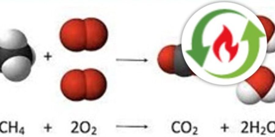

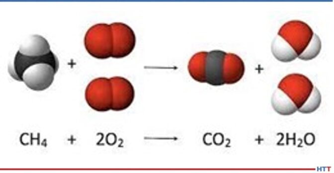
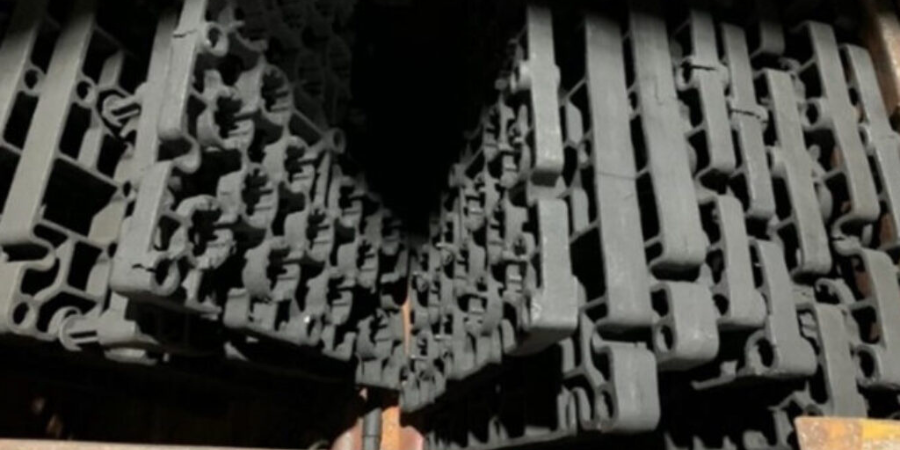


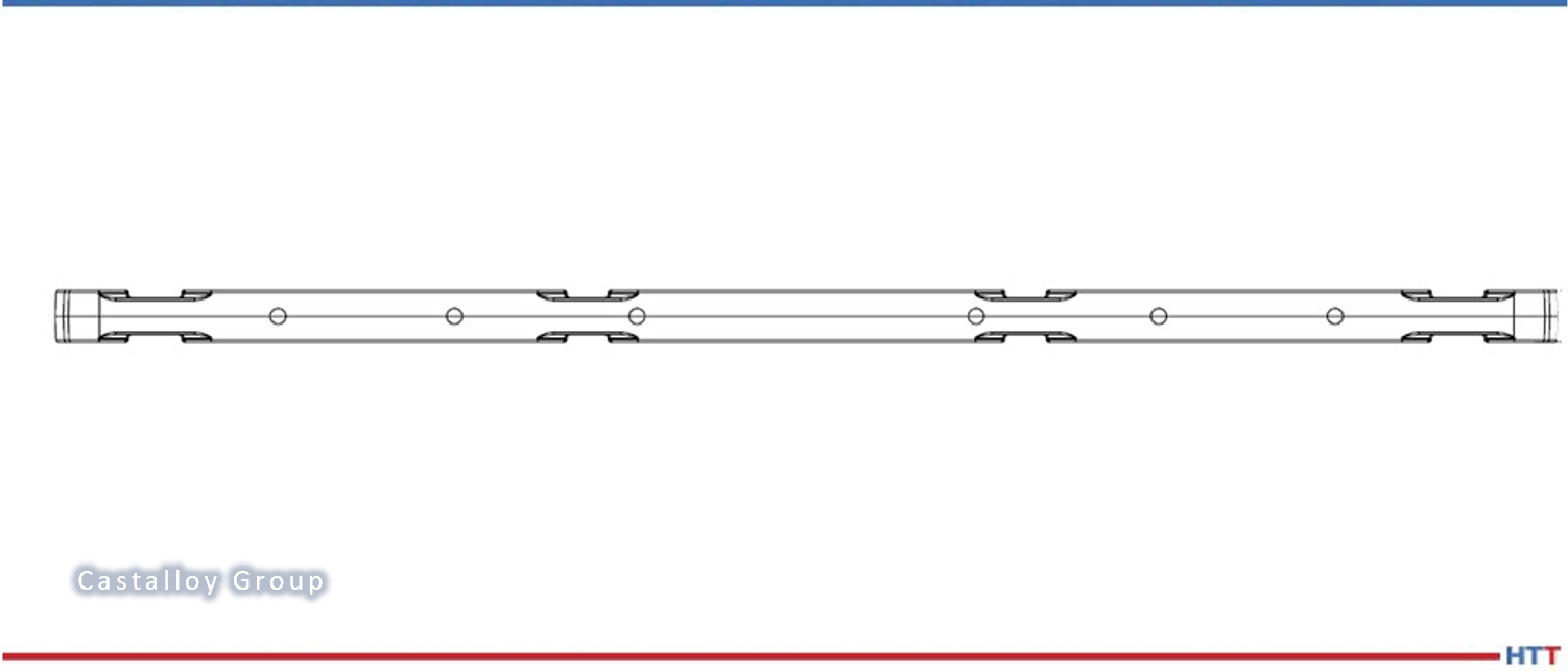
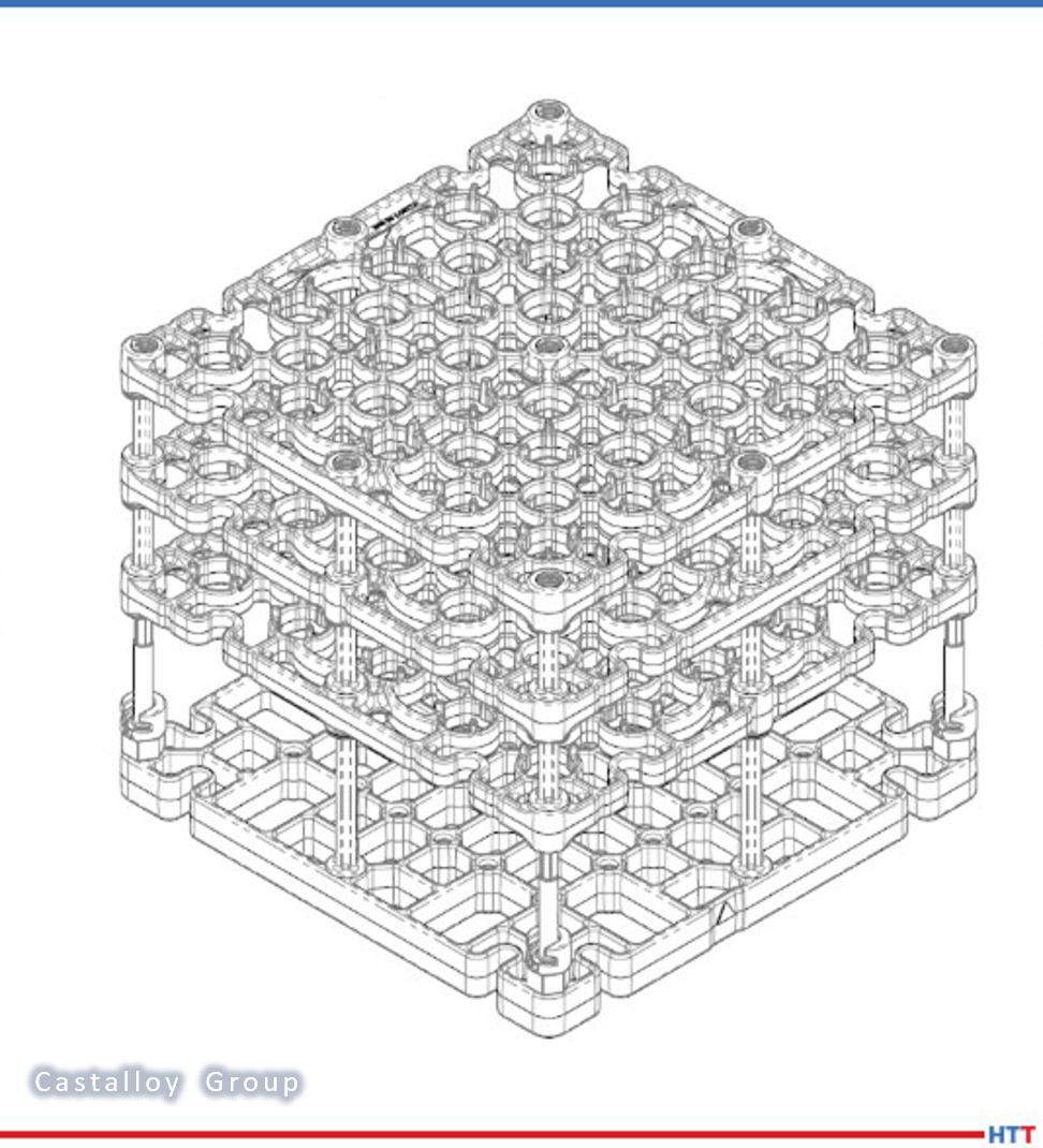

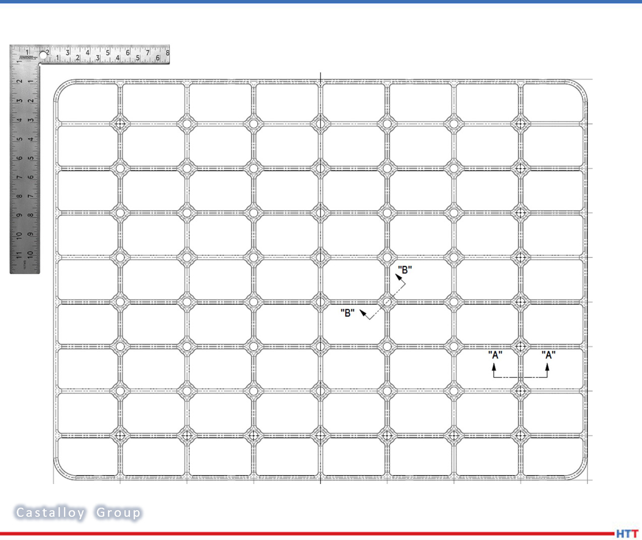

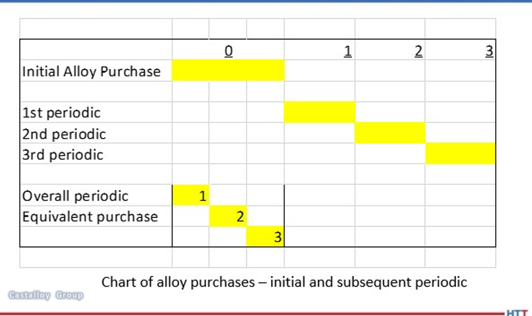
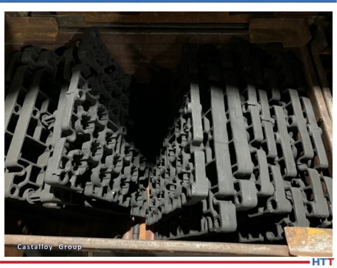


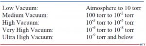
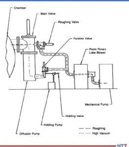

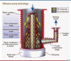

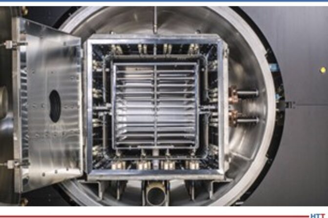
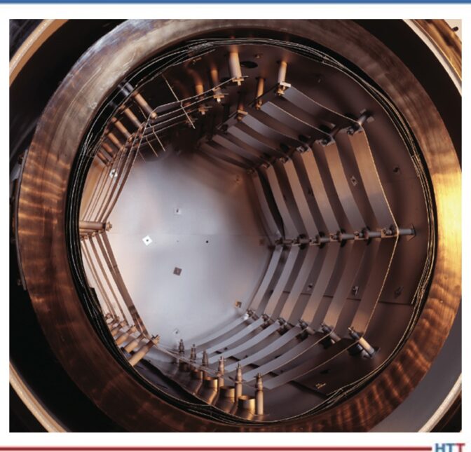
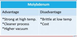
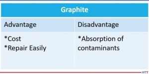
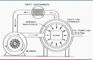
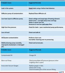

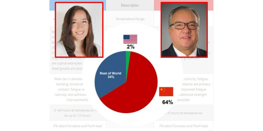
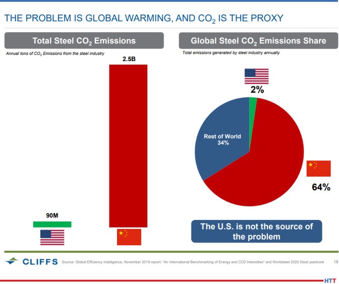
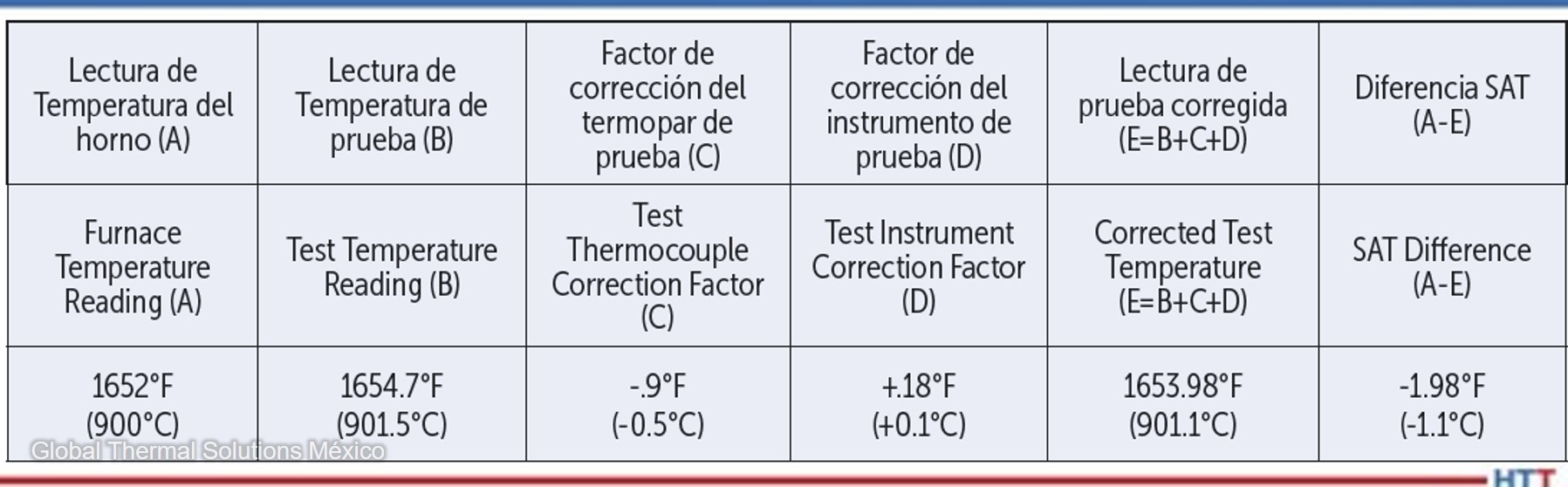


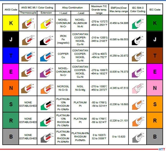

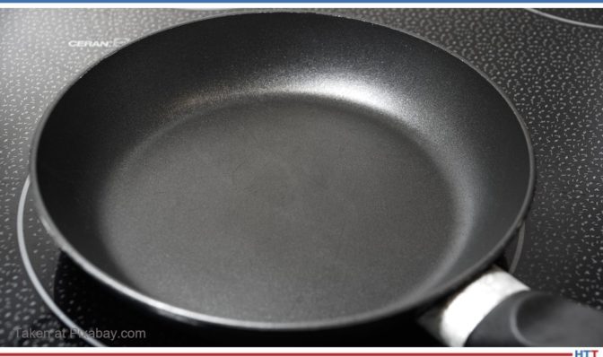
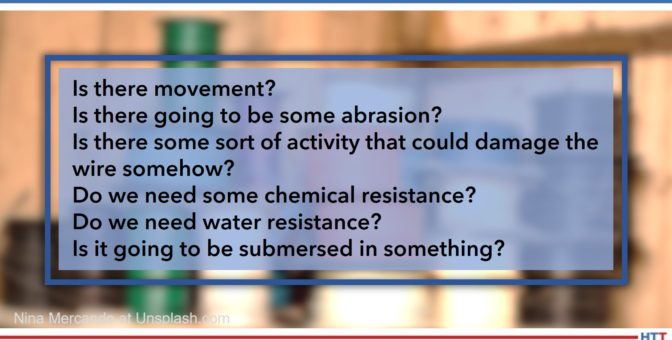


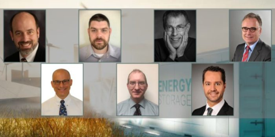


 Keenan Cokain, global sales and applications coordinator and Michael Cochran, an applications engineer, both from Pittsburgh’s Bloom Engineering, an industrial combustion and controls company, add another consideration: “Natural gas is a vital primary energy source globally and will likely remain so over the next 10 years. Although energy demands will likely show an overall decline in 2020, over the next 10 years, global natural gas consumption will likely rise as it continues to grow in comparison to other fossil fuels (such as oil and coal) as a percentage of the global primary energy consumed.