In this installment of Answers in the Atmosphere, David (Dave) Wolff, an independent expert focusing on industrial atmospheres for heat treat applications, explores the practical role of argon as a truly inert alternative to nitrogen in thermal processing.
This informative piece on argon’s unique properties, production challenges, and applications — from vacuum heat treating of titanium to powder metallurgy and additive manufacturing —was first released in Heat Treat Today’sFebruary 2026 Annual Air & Atmosphere Heat Treating print edition.
Akin Malas Business Development Manager / Metallurgist Linde
In this column, I’ve invited Akin Malas, business development manager and metallurgist at Linde, to bring his deep expertise in the subject of argon gas. What follows is the fruit of our discussion and continued conversations about this specialized yet indispensable industrial gas in thermal processing applications.
Compared to nitrogen (the industrial gas this column last covered), argon exhibits actual inertness, enabling its use in high-temperature environments and for processing metals that cannot tolerate nitrogen atmospheres, such as titanium and certain high-performance stainless steels. While argon is significantly higher cost than nitrogen, it remains far more economical than helium, another highly inert alternative.
Argon plays a vital role across multiple stages of metal processing, including:
Primary metallurgy: ladle stirring
Powder metallurgy: atomization of metal powders
Additive manufacturing: laser and electron-beam processes requiring inert chamber atmospheres
Vacuum heat treating: backfill gas for titanium and specialty alloys
Argon is used differently than nitrogen in most cases. Inexpensive nitrogen is often used as a utility pressurization gas, for scavenging, and blended with other gases (such as hydrogen); however, argon is most often used in pure form. Nitrogen is considered inert for heat treatment applications except in extraordinarily high temperatures or heat treatment of reactive metals, such as titanium and stainless steels. In this case, using an actual inert gas like argon or helium is necessary. Also, while nitrogen is virtually the same density as air and thus will diffuse throughout a vessel, argon is much denser than air and can be used to form a stratified inert layer.
Linde gas storage tanks | Image Credit: Linde
Both argon and nitrogen are separated from air in a cryogenic air separation unit (ASU), but there are three main factors that make argon much harder to make than nitrogen and thus much more expensive:
Argon is only 1% of air while nitrogen is 78% of air. Argon boils at nearly the same temperature as oxygen, making a separate purification process necessary. Those two factors mean that only the largest ASUs make enough argon to make it worth purifying.
Argon cannot economically be separated from air non-cryogenically (primarily because the percentage in air is so low), so there is no low-cost competition to cryogenic argon. Also, because argon is prized for its inertness, there is much less interest in argon that might be lower purity.
Because argon is made in only the largest ASUs (typically those serving very large steel mills) and because those plants tend to be geographically grouped, shipping distances for argon tend to be much farther than for nitrogen and oxygen, further driving up the costs.
Processors of titanium parts and parts made of some stainless steels, such as the 300 series stainless alloys (SS), cannot be processed in nitrogen-containing atmospheres, because the metals will nitride at heat treating temperatures. Hence these metals may be processed in a pure argon (for Ti) or hydrogen (for SS) atmosphere blends.
We’ll pick up this discussion next month to see what market options are available, particularly in the U.S.
About The Author:
David (Dave) Wolff Industrial Gas Professional Wolff Engineering
Dave Wolff has over 40 years of project engineering, industrial gas generation and application engineering, marketing, and sales experience. Dave holds a degree in engineering science from Dartmouth College. Currently, he consults in the areas of industrial gas and chemical new product development and commercial introduction, as well as market development and selling practices.
Carbon emissions reporting is no longer optional for heat treaters — it’s becoming a competitive and regulatory necessity. In this Sustainability Insights installment, Heat TreatToday examines research from Professor Fu Zhao and PhD candidate Lakshmi Srinivasan of Purdue University’s Heat Treating Consortium, detailing a new python-based carbon calculator built specifically for heat treat operations, how it models Scope 1, 2, and 3 emissions from furnace geometry and process parameters, and how in-house heat treaters can use it to meet growing transparency demands with minimal manual effort.
This informative piece was first released in Heat Treat Today’sFebruary 2026 Annual Air & Atmosphere Heat Treating print edition.
Emissions reporting has become an essential step. Navigating the requirements in an influx political environment only adds to the challenge. How can heat treaters remain in compliance? A tool designed through Purdue University’s Heat Treating Consortium (PHTC) may be the answer.
The consortium has funded research across heat treat projects ranging from the efficacy of novel quenchants to improving materials hardness. Roughly two years ago, the PHTC member companies requested research to develop a tool that would make carbon estimation possible.
Lakshmi Srinivasan, PhD Candidate in the School of Mechanical Engineering at Purdue UniversityProfessor Fu Zhao, Faculty Member at the School of Mechanical Engineering and the School of Sustainability Engineering and Environmental Engineering at Purdue University
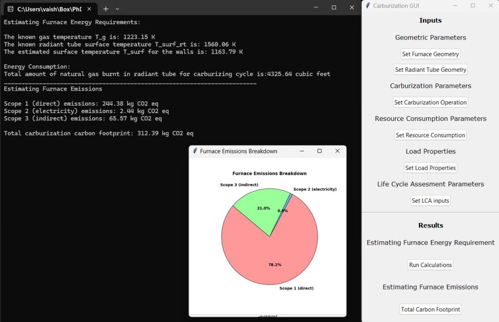
Professor Fu Zhao, faculty member at the School of Mechanical Engineering and the School of Sustainability Engineering and Environmental Engineering at Purdue, decided to take on this research request. He brought on PhD candidate Lakshmi Srinivasan, an astute researcher of energy systems modeling and life cycle assessment in the School of Mechanical Engineering, to research and develop the tool. “This project aims to model furnace energy requirements based on furnace geometry and heat treating input parameters,” Srinivasan explained. “From these modeling energy flows and furnace build inputs, we calculate Scope 1, Scope 2 and Scope 3 carbon emission associated with operating the furnace.”
Scope 1: Direct carbon emissions from energy consumption within the plan (e.g. combustion of natural gas or other fuels)
Scope 2: Indirect emissions from purchased electricity, steam, heat, or cooling
Scope 3: All other indirect emissions across the supply chain (e.g., suppliers, transportation, product use)
The tool is a python-based desktop application with scalability in mind. Since development targets the carburizing process for both market and regulatory reasons, it is highly focused on industry needs. Additionally, Zhao and Srinivasan built the tool for users to integrate additional features and data sets to align with new requirements or emerging technologies. They also underscored that the tool’s architecture is designed for growth as a web-based application.
Image of the digital carburization tracking tool | Image Credit: Srinivasan and Zhao
Ease of use is central. Zhao and Srinivasan have refined the tool to limit how much unique user input is required to generate an accurate output. The team explained this as particularly challenging, having examined alternatives to simplify the interface without oversimplify the “underlying physics.” They described how the final form of the tool will work, saying that once key parameters are entered (furnace type, processing temperatures, time, part geometry), the tool will automatically calculate energy usage and emissions with minimal manual intervention.
PHTC members, many of whom represent manufacturers with in-house heat treating, have shown great interest, providing feedback and resources to shape the development of the tool. Additional enthusiasm was found at IHEA’s annual SUMMIT in August 2025, where Srinivasan presented the tool’s development. When asked what inquiries have directed their research, Zhao and Srinivasan shared the following:
Versatility and functionality: How flexible is the tool in accommodating different furnace geometries, part geometries, furnace types, and heat treatment processes?
Part-based allocation: How does the tool allocate emissions accurately to individual parts or batches within a furnace load?
Location-specific emissions: How does it account for location-based variations in scope 2 and scope 3 emissions, such as differences in electricity generation or supply chain impacts?
Another challenge has been ensuring careful tool calibration and verification. To do so, the team has taken accurate, real-world natural gas and electricity consumption from heat treat operations, courtesy of PHTC members, to verify the model’s predicted energy consumption at defined furnace operating temperatures.
Eventually, some form of this tool will be made available to those outside the consortium. Currently, however, PHTC members are at the forefront of development and usage. The researchers underlined this, commenting, “This tool is particularly timely and essential for industry, as companies are increasingly expected to provide transparent and accurate emissions reporting.”
While the world of standards and regulations can feel like a minefield, benchmarked discussions of this tool reveal promising applications for in-house heat treaters in the near future.
El reporte de emisiones de carbono ya no es opcional para los especialistas en tratamiento térmico — se está convirtiendo en una necesidad competitiva y regulatoria. En esta entrega de Perspectivas de Sostenibilidad, Heat TreatToday examina la investigación del Profesor Fu Zhao y la candidata a Doctorado Lakshmi Srinivasan del Heat Treating Consortium de Purdue University, detallando una nueva calculadora de carbono basada en Python, desarrollada específicamente para operaciones de tratamiento térmico, cómo modela las emisiones del Alcance 1, 2 y 3 a partir de la geometría del horno y los parámetros del proceso, y cómo los especialistas en tratamiento térmico con operaciones internas pueden utilizarla para cumplir con las crecientes exigencias de transparencia con un mínimo de intervención manual.
Este artículo informativo se publicó por primera vez enHeat Treat Today’sFebruary 2026 Annual Air & Atmosphere Heat Treating print edition.
Si tiene comentarios o preguntas sobre este artículo, háganoslo saber en: editor@heattreattoday.com.
El reporte de emisiones se ha convertido en un paso esencial. Navegar los requisitos en un entorno político cambiante solo añade complejidad al desafío. ¿Cómo pueden los especialistas en Tratamiento Térmico mantenerse en el cumplimiento normativo? Una herramienta diseñada a través de Purdue University’s Heat Treating Consortium (PHTC, por sus siglas en inglés) podría ser la respuesta.
El consorcio ha financiado investigaciones en proyectos de tratamiento térmico que abarcan desde la eficacia de nuevos medios de temple hasta la mejora de dureza de los materiales. Hace aproximadamente dos años, las empresas miembros del PHTC solicitaron una investigación para el desarrollo de una herramienta que hiciera posible la estimación de carbono.
Lakshmi Srinivasan, Candidata a Doctorado en School of Mechanical Engineering at Purdue UniversityProfessor Fu Zhao, Miembro del Profesorado de School of Mechanical Engineering and the School of Sustainability Engineering and Environmental Engineering at Purdue University
El Profesor Fu Zhao, miembro del profesorado de School of Mechanical Engineering and the School of Sustainability Engineering and Environmental Engineering at Purdue decidió asumir esta solicitud de investigación. Incorporando a la candidata a Doctorado Lakshmi Srinivasan, una destacada investigadora en el modelado de sistemas energéticos y evaluación del ciclo de vida en School of Mechanical Engineering y la School of Sustainability Engineering and Environmental, para la investigación y desarrollo de esta herramienta. “Este proyecto tiene como objetivo modelar los requerimientos energéticos del horno en función de su geometría y los parámetros de entrada de tratamiento térmico”, explicó Srinivasan. “A partir de estos flujos energéticos modelados y de los insumos asociados a la construcción del horno, calculamos las emisiones de carbono del Alcance 1, Alcance 2 y Alcance 3 asociados a la operación del horno”.
Alcance 1: Emisiones directas de carbono derivadas del consumo de energía dentro de la planta (por ejemplo, combustión de gas natural u otros combustibles)
Alcance 2: Emisiones indirectas provenientes de electricidad, vapor, calor o enfriamiento adquiridos
Alcance 3: Todas las demás emisiones indirectas a lo largo de la cadena de suministro (por ejemplo, proveedores, transporte, uso del producto)
La herramienta es una aplicación de escritorio basada en Python, diseñada pensando en la escalabilidad. Dado que el desarrollo está orientado al proceso de carburizado tanto por razones de mercado como regulatorias, se encuentra altamente enfocada en las necesidades de la industria. Adicionalmente, Zhao y Srinivasan diseñaron la herramienta para que los usuarios puedan integrar características adicionales y conjuntos de datos que se alineen con nuevos requerimientos o tecnologías emergentes. También subrayaron que la arquitectura de la herramienta está pensada para su crecimiento como una aplicación basada en la web.
Imagen de la herramienta digital de seguimiento de carburizado | Image Credit: Srinivasan and Zhao
La facilidad de uso es un aspecto esencial. Zhao y Srinivasan han refinado la herramienta para limitar la cantidad de entradas únicas requeridas por el usuario para generar un resultado preciso. El equipo explicó que este aspecto fue particularmente desafiante, ya que se examinaron alternativas para simplificar la interfaz sin simplificar en exceso la “física subyacente”. Describieron como funcionará la versión final de la herramienta, explicando que una vez que se introduzcan los parámetros clave (tipo de horno, temperaturas de proceso, tiempo, pieza) la herramienta automáticamente calculará la energía usada y las emisiones con una intervención manual mínima.
Los miembros del PHTC, de los cuales muchos representan compañías manufactureras que cuentan con tratamiento térmico interno, han mostrado interés, proporcionando retroalimentación y recursos para dar forma al desarrollo de la herramienta. Un entusiasmo adicional se observó durante el IHEA’s annual SUMMIT en agosto de 2025, donde Srinivasan presentó el desarrollo de la herramienta. Cuando se les preguntó qué interrogantes han guiado su investigación, Zhao y Srinivasan compartieron lo siguiente:
Versatilidad y funcionalidad: ¿Qué tan flexible es la herramienta para adaptarse a diferentes geometrías de horno, geometrías de piezas, tipos de hornos y procesos de tratamiento térmico?
Asignación basada en piezas: ¿Cómo asigna la herramienta las emisiones de manera precisa a piezas individuales o lotes de una carga dentro del horno?
Emisiones específicas por ubicación: ¿Cómo considera las variaciones regionales en las emisiones del Alcance 2 y Alcance 3, tales como las diferencias en la generación de electricidad o los impactos de la cadena de suministro?
Otro desafío ha sido garantizar la calibración y verificación cuidadosa de la herramienta. Para ello el equipo ha utilizado datos reales y precisos de consumo de gas natural y electricidad provenientes de operaciones de tratamiento térmico, cortesía de los miembros del PHTC, con el fin de verificar el consumo energético predicho por el modelo a temperaturas de operación definidas del horno.
Eventualmente alguna versión de esta herramienta estará disponible para usuarios fuera del consorcio. Sin embargo, actualmente, los miembros del PHTC se encuentran a la vanguardia tanto del desarrollo como del uso. Los investigadores enfatizaron este punto: “Esta herramienta es particularmente oportuna y esencial para la industria, ya que las empresas enfrentan una creciente expectativa de proporcionar reportes de emisiones transparentes y precisos”.
Si bien el mundo de las normas y regulaciones puede sentirse como un campo minado, las discusiones comparativas sobre esta herramienta revelan aplicaciones prometedoras a corto plazo para los especialistas en tratamiento térmico con operaciones internas.
Ask The Heat Treat Doctor® has returned to bring sage advice to Heat Treat Today readers, answer questions about heat treating, brazing, sintering, and other types of thermal treatments, as well as metallurgy, equipment, and process-related issues. In this installment, Dan Herring examines the essential role of heat treatment in gear performance: exploring the key material and design considerations for power transmission gears, the difference between through hardening and case hardening, and the atmosphere heat treatment processes — from carburizing and carbonitriding to nitriding and nitrocarburizing — that determine how well a gear handles load, wear, and fatigue in heavy-duty applications.
This informative piece was first released in Heat Treat Today’sFebruary 2026 Annual Air & Atmosphere Heat Treating print edition.
Have questions or feedback? We’d love to hear from you — reach out to our editorial team at editor@heattreattoday.com.
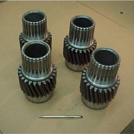
Gears play an essential role in the performance of many products that we rely on in our everyday lives. When we think about gears, we generally separate them into two categories: motion-carrying and power transmission. Motion-carrying gears are generally nonferrous alloys or plastics, while load bearing power transmission gears (Figure 1) are usually manufactured from ferrous alloys and are intended for heavy-duty service applications.
Figure 1. Typical off-highway truck power transmission gears | Image Credit: The Heat Treat Doctor®
Gear Materials & Engineering
Power transmission gears involve a wide variety of steels and cast irons. In all gears, the choice of material must be made only after careful consideration of the performance demanded by the application end-use and total manufactured cost, taking into consideration such issues as pre- and post-machining economics.
Key design considerations require an analysis of the type of applied load, whether gradual or instantaneous, and the desired mechanical properties, such as bending fatigue strength or wear resistance — all of which will define core strength and heat treating requirements.
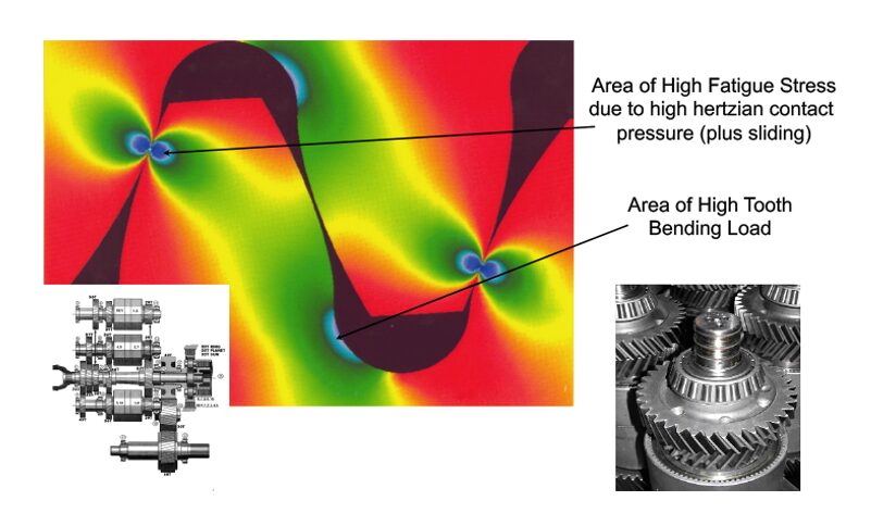
Figure 2. Stress profile in a heavy-duty transmission gear | Image Credit: The Heat Treat Doctor®
It is important for the designer to understand that each area in the gear tooth profile sees different service demands (Figure 2). Consideration must be given to the forces that will act on the gear teeth with tooth bending and contact stress, resistance to scoring and wear, and fatigue issues being paramount. For example, in the root area, good surface hardness and high residual compressive stress are desired to improve endurance or bending fatigue life. At the pitch diameter, a combination of high hardness and adequate subsurface strength are necessary to handle contract stress and wear and to prevent spalling.
Some of the factors that influence fatigue strength are:
Hardness distribution, a function of:
Case hardness
Case depth
Core hardness
Microstructure, a function of:
Retained austenite percentage
Grain size
Carbide size, type, and distribution
Non-martensitic phases
Defect control, a function of:
Residual compressive stress
Surface finish and geometry
Intergranular toughness
In the total manufacturing scheme, a synergistic relationship must exist between the material selection process, engineering design, and manufacturing (including heat treatment). A balance of the priorities in each discipline must be reached to achieve the optimization necessary for the ultimate performance of the gear design. This is often not an easy task.
Various atmosphere heat treatment methods are used for most types of gears including pre-hardening steps (e.g., annealing, normalizing, stress relief) and hardening processes (e.g., neutral hardening and case hardening).
Hardening
Neutral (aka through hardening) refers to heat treatment methods that do not produce a case. Examples of commonly through-hardened gear steels are AISI/SAE grades 1045, 4130, 4140, 4145, 4340, and 8640. It is important to note that hardness uniformity should not be assumed throughout the gear tooth. Since the outside of a gear is cooled faster than the inside, there will be a hardness gradient developed. The final hardness is dependent on the amount of carbon in the steel. The depth of hardness depends on the hardenability of the steel.
Through hardening can be performed either before or after the gear teeth are cut. When gear teeth will be cut after the part has been hardened, machinability becomes an important factor based on final hardness. The hardness is achieved by heating the material into the austenitic range, typically 815°C–875°C (1500°F–1600°F), followed by quenching and tempering.
Case Hardening
By contrast, case hardening is used to produce a hard, wear resistant case (surface layer) on top of a ductile, shock resistant interior (core). The idea behind case hardening is to keep the core of the gear tooth at a level under 40 HRC to avoid tooth breakage while hardening the outer surface to increase pitting resistance.
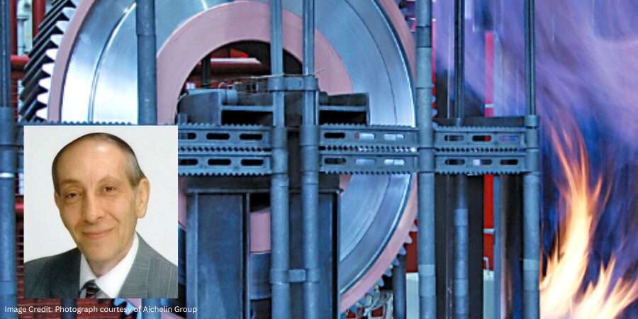
Carburizing
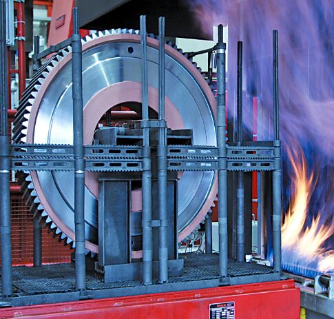
Figure 3. Atmosphere carburizing of large gears | Image Credit: Photograph courtesy of Aichelin Group
Atmosphere carburizing is the most common of the case hardening methods in use today and can handle a diverse range of part sizes and load configurations (Figure 3). In general, a properly carburized gear will be able to handle somewhere between 30–50% more load than a through-hardened gear. Examples of commonly carburized gear steels include AISI/SAE grades 1018, 4320, 5120, 8620, and 9310, as well as international grades, such as 20MnCr5, 17CrNiMo6, 18CrNiMo7-6, and 20MoCr4.
Atmosphere carburizing is typically performed in the temperature range of 870°C–955°C (1600°F–1750°F) although temperatures up to 1010°C (1800°F) are used for deep case work. Carburizing case depths can vary over a broad range, typically 0.13–8.25 mm (0.005–0.325 inches).
Carbonitriding
Carbonitriding is a modification of the carburizing process, not a form of nitriding. This modification consists of introducing ammonia into the carburizing atmosphere to add nitrogen to the carburized case as it is being produced. Examples of gear steels that are commonly carbonitrided include AISI/SAE 1018, 1117, and 12L14.
Carbonitriding is done at a lower temperature than carburizing, typically between 790°C–900°C (1450°F–1650°F), and for a shorter time. Combine this with the fact that nitrogen inhibits the diffusion of carbon, and what generally results is a shallower case than is typical for carburized parts. A carbonitrided case is usually between 0.075–0.75 mm (0.003–0.030 inches) deep.
Nitriding
Nitriding is another surface treatment process that has as its objective increasing surface hardness. One of the appeals of this process is that rapid quenching is not required, hence dimensional changes are kept to a minimum. It is not suitable for all gear applications; one of its limitations is that the extremely high surface hardness case produced has a more brittle nature than say that produced by the carburizing process. Despite this fact, in a number of applications, nitriding has proved to be a viable alternative. Examples of commonly nitrided gear steels include AISI/SAE 4140, 4150, 4340, and Nitralloy® 135M.
Nitriding is typically done in the range of 495°C–565°C (925°F–1050°F). Case depth and case hardness properties vary not only with the duration and type of nitriding being performed but also with steel composition, prior structure, and core hardness. Typically, case depths are between 0.20–0.65 mm (0.008–0.025 inches) and take from 10 to 80 hours to produce.
Nitrocarburizing (Ferritic or Austenitic)
Nitrocarburizing is a modification of nitriding, not a form of carburizing. In the process, nitrogen and carbon are simultaneously introduced into the steel while it is in a ferritic or at times an austenitic condition. A very thin “white” or “compound” layer is formed during the process, as well as an underlying “diffusion” zone. Like nitriding, rapid quenching is not required. Examples of gear steels that are commonly nitrocarburized include AISI/SAE grades 4140, 5160, 8620, and certain tool steels, such as H11 and H13.
Nitrocarburizing is normally performed at 550°C–600°C (1025°F–1110°F) and can be used to produce a 58 HRC minimum hardness, with this value increasing dependent on the base material. White layer depths range from 0.0013–0.056 mm (0.00005–0.0022 inches) with diffusion zones from 0.03–0.80 mm (0.0013–0.032 inches) being typical.
In Summary
There are many ways to heat treat gears. While atmosphere heat treatment (discussed above) is perhaps the most widely used technology today, other types of heat treatments, namely vacuum and induction hardening, are becoming more and more common methods. These will be discussed in Part Two.
About the Author
Dan Herring “The Heat Treat Doctor” The HERRING GROUP, Inc.
Dan Herring has been in the industry for over 50 years and has gained vast experience in fields that include materials science, engineering, metallurgy, new product research, and many other areas. He is the author of six books and over 700 technical articles.
What do aerospace and industrial heating vessels have in common? Backups for essential systems. In this Technical Tuesday installment, Bruce Yates, president of Protection Controls Inc., explores how NFPA 86 Standard for Oven and Furnaces addresses redundant flame safety, compares common sensing approaches, and highlights recent advances in UV scanner technology that improve reliability and reduce maintenance risks.
This informative piece was first released in Heat Treat Today’sFebruary 2026 Air & Atmosphere Heat Treating print edition.
Introduction
Boeing Aircraft lost billions of dollars before realizing that the 737 MAX’s MCAS (Maneuvering Characteristics Augmentation System) needed a redundant angle-of-attack vane to prevent erroneous MCAS-induced drive commands. Lockheed Martin uses dual-redundant MIL-STD-1553 data bus (that is, a shared communication pathway for exchanging data between electronic systems) on its Apache Guardian attack helicopter for target acquisition and cueing for the helicopter’s fire-control radar system. Spacecraft internal Active Thermal Control Systems (ATCSs) can either be a fully redundant thermal-control loop or a single loop system that is equipped with a redundant accumulator to be activated if needed. The accumulator represents a single point of failure that can result in a loss of crew.
Aerospace is not the only industry where redundancy is an important aspect of safety. It is critical in the industrial heating industry. NFPA 86 Standard for Ovens and Furnaces has for many years required redundant pilot gas valves and redundant main gas valves.
Let’s discuss redundant flame safety.
Redundancy in Industrial Heating
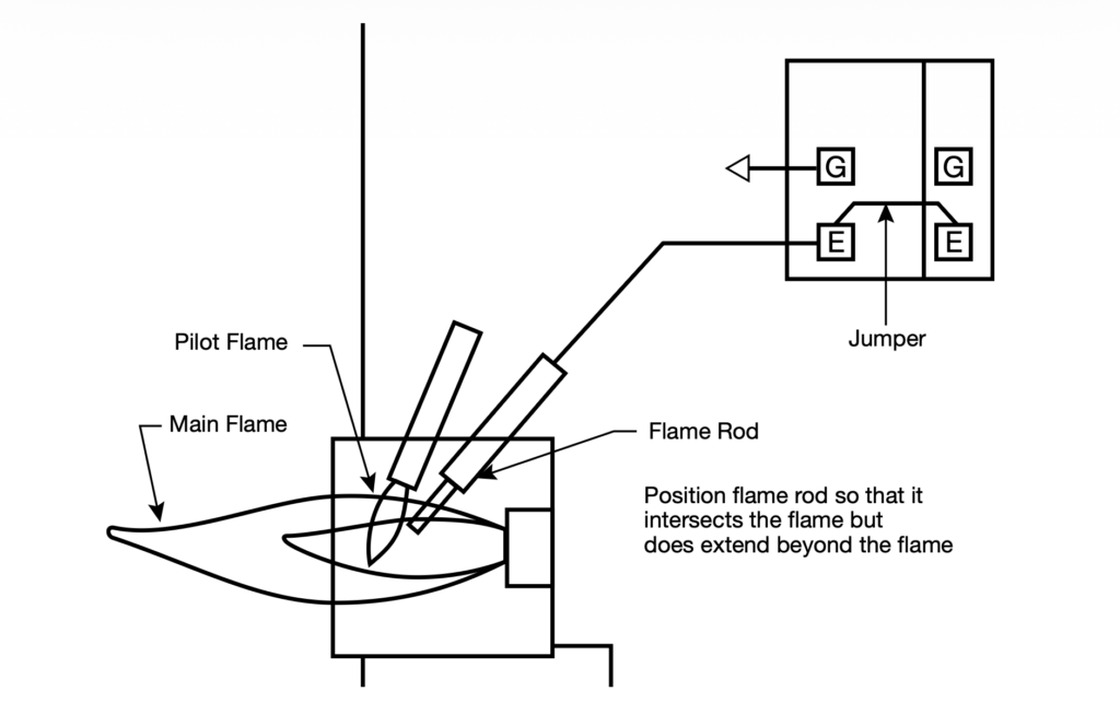
There are two types of flame sensors generally used on industrial burners: flame rods and ultraviolet scanners. Flame rods are simply stainless steel rods that intersect the burner flame. A voltage potential from the combustion safeguard is applied to the flame rod. When a flame is present, an electrical current (measured in millionths of an amp) flows from the flame rod through the ionized gases of the flame to the burner, which is grounded. This current is amplified in the combustion safeguard and energizes a relay output to power the fuel valves (see Main Image).
Redundancy can be achieved by using a two-burner control with one flame rod. The flame signal from the flame rod goes to the sensor input of both positions of the two-burner control (Figure 1).
We will devote the rest of this article to UV scanners (Figure 3).
Figure 1. Redundant flame safety with a single burner flame safeguard with a flame rod sensor
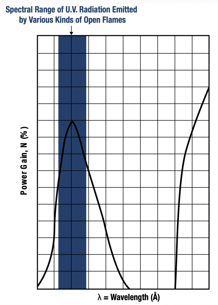
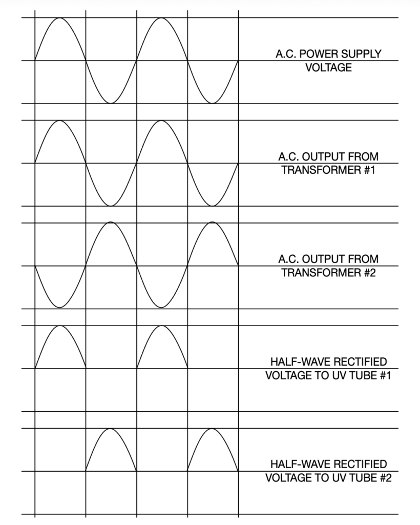
Figure 2. Solar radiation begins at approximately 2,800 Å and is therefore not detectable by the flame rod sensor.Figure 3. Demonstration of two independent UV tubes producing UV rays out of sync with one another | Image Credit: Protection Controls
Redundant Flame Safety with UV Scanners
The tube of a UV scanner responds only to radiation in the spectrum of 1,900 to 2,300 Å (Figure 2). Peak response is at 2,100 Å (210 nm). Solar UV starts at about 2,800 Å, as shown in Figure 2, and is therefore not detectable by the device. Solar radiation, of course, extends into the visible spectrum (4,000 Å) and extends into the infra-red spectrum. A UV tube consists of a fused silica or UV glass envelope, two electrodes, and a gas contained in this envelope. This is called a cold-cathode gas-discharge tube.
This tube conducts or ignites when it is irradiated with ultraviolet light and when sufficient voltage potential exists across the two electrodes. The electrodes can be made of tungsten, molybdenum, or nickel. When a photon of sufficient energy is absorbed into the cathode electrode, electrons are emitted and are drawn to the anode. A larger cathode allows more electrons to avalanche, causing higher current flow and thus higher sensitivity to UV. There are high sensitivity UV scanners designed for special burners that will produce low UV, such as one designed by Protection Controls, Inc.
The gas in the tube is usually a helium-hydrogen ionizable mix. Electrons released by the cathode release electrons in the ionized gas, becoming a self-sustaining discharge much greater than that of the originally generated electrons and producing a very high current gain or avalanche effect. The sensitivity of a tube will very slowly decrease over a period of time. Replacement should be made after 8,000 hours of operation. The current produced by the photoelectrons is measured in millionths of an ampere, so this current is amplified in the combustion safeguard to energize a relay that can then energize the fuel valves.
Critical Maintenance to Avoid Tube Gas Contamination
While UV scanners are very reliable, tube gas contamination may occur with large temperature shock (ΔTEMP/ΔTime) or large physical shock (a 2-inch drop may cause 100G shock), causing the electrode to UV glass envelope seal integrity to be compromised. Because of this, it is possible for a UV tube to conduct current when no UV is incident upon it. This would normally be detected during the flame safeguard safe start check. When an indicated flame on condition exists prior to purge or ignition, the safe start check relay prevents ignition and gas valve energization.
In addition to safe start check before every heating cycle, a monthly preventative maintenance schedule should be in place if the burner is used daily. This consists of closing a manual gas valve. The electrically powered gas valves should close in two to four seconds as the UV scanner and combustion safeguard respond to loss of flame.
If a burner is in continuous service, we recommend that this maintenance schedule be performed weekly. An alternative to this is to use a self-checking ultraviolet scanner and control. In the past, this type of scanner involved an electrically operated shutter, which alternately would block and allow UV to the tube. However, having a mechanical device operating close to the burner heat and vibration is a recipe for frequent and premature failures; it is typically rated for only 140°F to 175°F maximum and is quite expensive.
Going Shutterless
Figure 4. Note how each amplifier has its own flame relay | Image Credit: Protection Controls
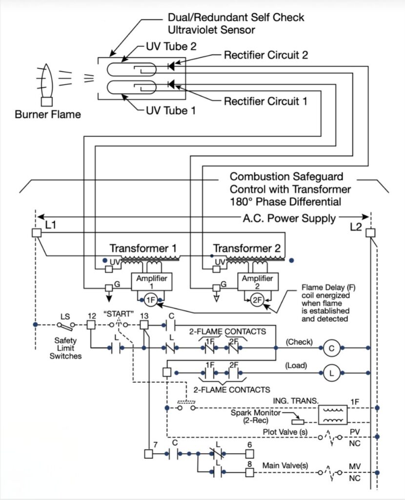
Newer designs are available that completely avoid using a mechanical operating device to moderate the UV, increasing reliability and durability. For example, the Dual/Redundant Self Check UltraViolet Flame Sensor and Combustion Safeguard Control from Protection Controls includes two UV tubes in one ultraviolet sensor to monitor one burner flame. UV tubes respond to welding sparks, ignition sparks, lightning, bright incandescent or fluorescent light, solar radiation, gamma rays, and x-rays.
Since UV tubes produce UV rays when they conduct, two UV tubes in one sensor would not normally be suitable for sensing a burner flame, as one UV tube could be responding to the other tube and not the flame. But in the case of this safety control, two voltage supplies to the UV tubes are out of phase with each other. When one UV tube is powered and may respond to UV rays, the other UV tube is off. Additionally, the two UV tubes are powered through two rectifier circuits from two transformers that are out of phase with each other. The two UV tubes are powered and sense UV from the flame on alternating half cycles (Figure 3).
Each UV tube and rectifier circuit provides input to its amplifier. Each amplifier provides input to its own flame relay (Figure 4). Upon burner startup, before burner ignition, if either UV tube is in conduction, the safe start check circuit does not permit powering the fuel valve.
During the burner run cycle, if either UV tube fails in the conduction state, the cycle will safely continue with the other UV tube sensing the burner flame. See Figure 5.
Regardless of which sensor option you choose, accounting for flame redundancy and ensuring your maintenance plan is proactive enough for the method chosen is key to a safe manufacturing environment.
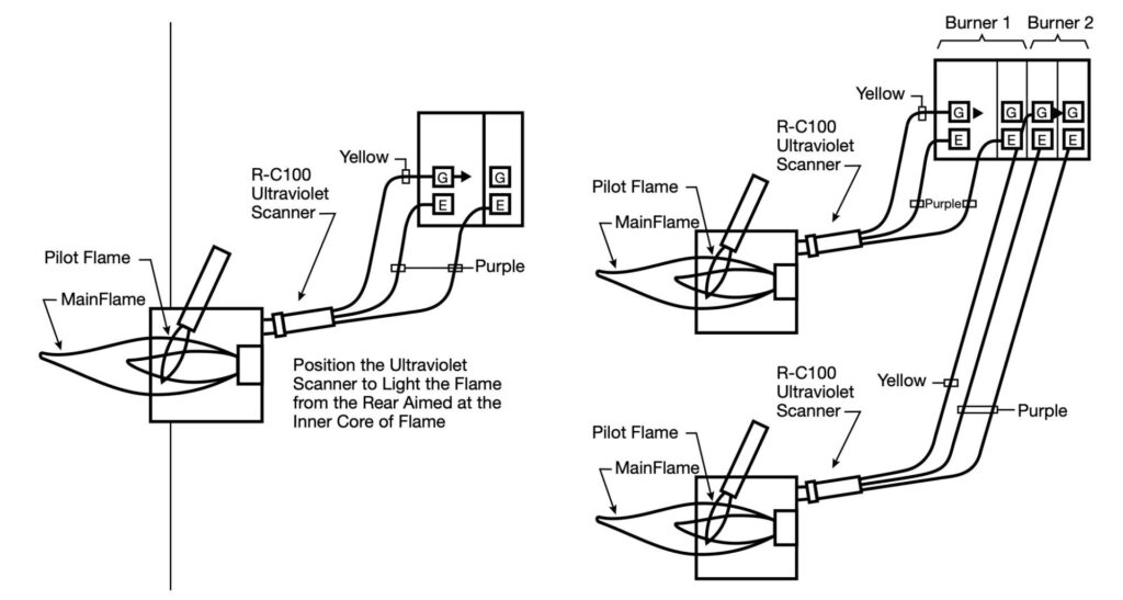
Figure 5. Redundant flame safety for single- and multi-burner flame safeguards: (a) redundant flame safety with a single burner flame safeguard with an ultraviolet sensor and (b) redundant flame safeguard (2-burner shown) with an ultraviolet sensor. | Image Credit: Protection Controls
About The Author:
Bruce Yates President Protection Controls, Inc.
Bruce Yates is the president of Protection Controls and is involved with management, sales, and engineering responsibilities. He graduated from the University of Illinois with a Bachelor of Science in Electrical Engineering in 1968. He works with his brother Douglas in the family-owned flame safeguard control manufacturing company, started by his father, James, and uncle, Robert, in 1953.
In this installment of Answers in the Atmosphere, David (Dave) Wolff, an independent expert focusing on industrial atmospheres for heat treat applications, highlights the practical value of smartphone apps designed for industrial gas calculations and conversions.
This informative piece on mobile tools that simplify gas property calculations, unit conversions, and storage or flow-rate estimations — drawing attention to apps developed by major gas suppliers and equipment providers that help heat treaters access critical data in the field —was first released in Heat Treat Today’sJanuary 2026 Annual Technologies to Watch print edition.
The field of industrial gases is complicated by the fact that the physical characteristics of gases depend on the temperature and pressure at the time of measurement. Industrial gases may be delivered and stored as cryogenic liquids and highly pressurized gases, though they are generally used in relatively low-pressure gaseous form. Additionally, gases may be used for different purposes; for example, hydrogen may be used as a metallurgical atmosphere or as a burner fuel. As such, users need a ready source of data on various industrial gases to make necessary calculations.
Image Credit: Open Library/Internet Archive
Years ago, industrial gas users had to rely on data tables in publications like the CRC Handbook of Chemistry and Physics — the nearly 8 lb, $195 hardbound handbook that has been published continuously since 1914 and is currently on its 106th edition.
Today, there are many more mobile solutions in the form of smartphone applications. Several of the major gas providers have developed handy apps available for both Apple and Android operating systems to simplify gas conversions and calculations. Equipment providers have also developed apps to help understand the specifics of their equipment. All of these can be helpful to metals thermal processors, including heat treaters at in-house processing operations.
Some examples follow:
Air ProductsandLinde both provide powerful conversion engines that enable users to convert from imperial to metric units, from mass to volume measurements, and from liquid to gaseous volumes for common industrial gases. For example, users can calculate how many hours of atmosphere coverage 6,000 gallons of liquid hydrogen stored in a tank will provide.
Cyl-Tec, Inc. has developed an app that focuses on calculations primarily specific to cryogenic and pressurized gas storage. In addition to unit of measure conversions for each common industrial gas, the app provides detailed information on each of the storage vessels that the company makes.
WITT-Gasetechnik of Germany has developed an app to support their gas safety and controls business. Their products include gas mixers, gas analyzers, regulators, and other controls. The app provides a variety of gas blending and measurement information, including welding gas blend suggestions, unit conversion, and flow rate calculators.
Gasmet of Finland has developed an app that simplifies calculation of dewpoint and combustion products depending on the fuel being combusted.
While these suppliers hope that you will buy their products, be assured that the measurements and conversions performed with their tools, and the recommendations generated, will be equally applicable to products and systems supplied by others.
I suggest you create a folder called “calculations and conversions” on your smartphone and load it up with several of these apps while you are connected to your home or office internet, so that you will have the apps handy when you are away from your standard technical resources.
About The Author:
David (Dave) Wolff Industrial Gas Professional Wolff Engineering
Dave Wolff has over 40 years of project engineering, industrial gas generation and application engineering, marketing, and sales experience. Dave holds a degree in engineering science from Dartmouth College. Currently, he consults in the areas of industrial gas and chemical new product development and commercial introduction, as well as market development and selling practices.
When a load hangs up during quenching, seconds matter and improvised decisions can escalate risk. In this Technical Tuesday installment, Bruno Scomazzon, general manager of Precision Heat Treat Ltd., outlines a step-by-step emergency response procedure for exactly this scenario, which is one of the most dangerous in atmosphere heat treating. Drawing on real-world experience, this guide is intended to help companies develop their own effective procedures for maintaining safety, controlling furnace conditions, and coordinating with emergency responders in high-risk situations.
This informative piece was first released in Heat Treat Today’sFebruary 2026 Annual Air & Atmosphere Heat Treating print edition.
If you have comments or questions about this article, please let us know at: editor@heattreattoday.com
A load has been transferred to the quench and the elevator is lowering into the oil, but the load becomes hung up and fails to fully submerge. The inner door successfully closes, and the outer (front) door remains closed.
This is an extremely high-risk situation requiring strict adherence to emergency procedures. The goal is to protect: first the personnel (minimize the chance of injury or escalation of the situation), then the facility, and finally the equipment.
1. Immediate Actions
DO NOT Open Outer Door
There may be a natural urge to assess the situation but resist temptation. DO NOT stand in front of or directly beside the outer door and never open it during an active hang-up. Opening this door can introduce oxygen to a hot chamber, causing:
Explosions or flash fires.
Loss of containment due to door warping or mechanical failure.
In extreme cases, the outer door may be compromised (blown off, stuck open, or partially open) with visible flames. This warrants immediate escalation to the fire department.
If Outer Door Cannot Be Closed
In this scenario, immediately notify the fire department and advise them to prepare for a foam response. DO NOT allow the use of water. This may trigger violent reactions with oil or atmosphere and spread the fire!
Internal trained responders should:
Don PPE.
Retrieve fire suppression gear.
Be ready to protect critical systems until responders arrive.
DO NOT shut down the furnace.
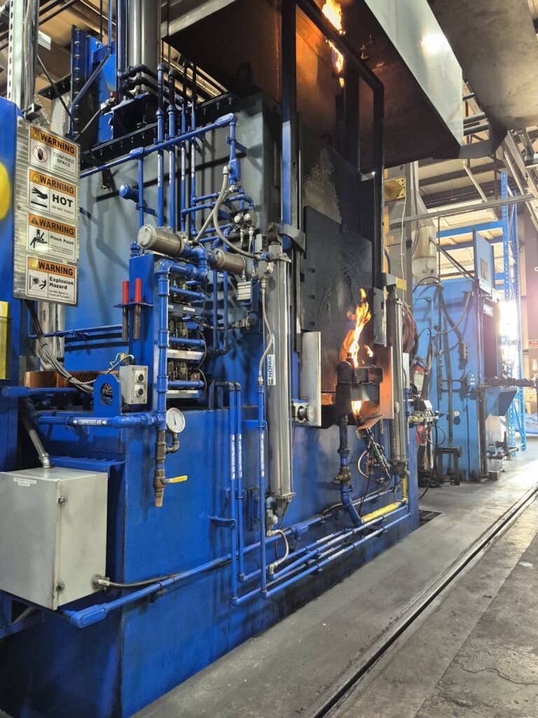
Figure 1. Atmosphere furnace during normal operation | Image Credit: Precision Heat Treat Ltd.Figure 2. Vestibule door partially opened during a controlled simulation to illustrate gas release behavior — not an actual incident | Image Credit: Precision Heat Treat Ltd.
2. Maintain Electrical Power
To ensure essential systems stay active, you must maintain electrical power. Ensure these systems stay active:
Set the furnace cycle to manual mode from auto mode. This will bypass any PLC sequencing from auto cycling doors, elevators, and handlers.
Keep the pilots lit.
Keep the oil cooler running to prevent tank overheating.
Shut off oil heaters to prevent additional heat loading in the quench tank.
Keep quench agitation on low during the entire period to assist in lowering the temperature at the interface surface area between the hot load and the oil. This prevents stratification and dissipates radiant heat into the oil.
Keep the recirculating fan running.
Keep the instrumentation functioning for monitoring.
NOTE: Loss of these systems eliminates visibility, atmosphere control, and safe response options.
3. Atmosphere Management
Maintain a protective atmosphere and positive furnace pressure to prevent oxygen ingress and uncontrolled combustion:
Set the carbon control to “0”.
Shut off the enriching gas.
Shut off the ammonia.
Shut off the dilution air.
Nitrogen Purge
These steps depend on whether a nitrogen purge is available; it is highly advised that nitrogen purge be available for all IQ or straight through units. Be sure you understand how long it takes for your specific furnace to fully purge endothermic gas. While NFPA 86 recommends five volume turnovers, some experts advise planning for up to ten per hour in an emergency. Each furnace should have established purge data under normal conditions so operators can act with confidence when time is critical.
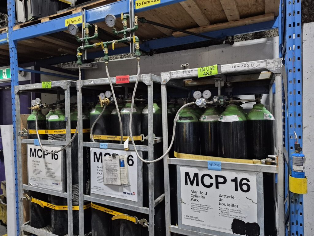
Figure 3. Bulk nitrogen supply used for emergency purging and atmosphere control | Image Credit: Precision Heat Treat Ltd.
Begin a nitrogen purge immediately (if available) and maintain it throughout the event.
Use at least the minimum flow rate specified in your documentation. If safe, higher flow may be used to help displace flammable gases from the heating and quench chambers.
Maintain furnace temperature at 1500°F during the purge.
Residual pockets of Endo gas may remain trapped in less ventilated areas. If the chamber temperature drops below the ignition point before all flammable gas has been displaced, the introduction of oxygen could trigger an explosion. In some cases, trapped Endo and pressure imbalances can lead to sudden releases (“furnace burp”), where oil or gas is expelled due to internal pressure buildup.
After the Purge
The goal of the nitrogen purge is to displace Endothermic gas with an inert atmosphere while maintaining elevated temperature to assist in burning off residual flammable gases and preventing dangerous mixtures. This process must ensure positive pressure throughout the furnace.
A purge followed by plunge cooling in nitrogen is a valid approach if the purge is verifiably complete.
Depending on furnace size and cooling rate:
Larger furnaces may cool slowly enough for a complete purge.
Smaller or faster-cooling units may require a brief temperature hold before controlled cooling or plunge cooling.
NOTE: Once the hung-up load cools to a safe temperature (~150°F), perform a standard shutdown.
Without Nitrogen (in Endo)
If there is no nitrogen purge, or it is insufficient, the only option is to let the hung-up load cool in the vestibule while continuing to burn Endo and maintain the furnace temperature at 1500°F. Once the vestibule/oil tank cools below 150°F and the danger has passed, initiate a standard furnace shutdown.
4. Safety Management
Alert the local fire department immediately. If the situation becomes unmanageable, or if there is any doubt about the ability to maintain control, evacuate the facility and wait for trained professionals. The safety of plant personnel is paramount.
Notify plant safety and site management.
Evacuate all non-essential personnel from the heat treat area.
Inform all departments that a high-risk incident is in progress.
Fire departments are most effective when they are familiar with your facility before an emergency occurs. Make sure they know the layout of your operation, including:
Oil tank locations and sizes
Electrical panels
Gas shutoffs
Hot zones
5. Controlled Cooling Period
Maintain atmosphere protection throughout the event.
DO NOT open doors until the vestibule’s temperature is low and stable.
Cooling time will depend on load mass and heat retention. Expect five or more hours.
Use furnace pressure stability, effluent observations, and gas behavior as indirect temperature indicators.
6. Load Recovery Procedure
Once cooled and stabilized, perform a standard shutdown, starting with the removal of endothermic gas if applicable.
DO NOT attempt manual load removal until the system is verified safe.
Only maintenance personnel may retrieve the load, using PPE and appropriate tools.
7. Fire Department Familiarization
Every facility should build rapport with the local fire department before an emergency ever happens. Schedule annual walkthroughs and identify the following:
Number of furnaces
Quench oil tank volumes
Hot zone and live panel locations
Emergency shutoff points
Stuck doors are commonly caused by failed pneumatic valves. Shutting off and bleeding compressed air may allow the mechanism to reset. Always consult your equipment manual or the manufacturer before attempting corrective action.
The fire inspector conducting walkthroughs is not the one coming to fight your fires — train the ones who are.
8. Post-Incident Protocol
Before returning the furnace to service:
Conduct a formal investigation.
Identify and correct root cause(s).
Document all key parameters and actions taken.
Re-train operators as needed.
Furnace Signage
An operator is likely to read your safety plan but may forget a vital protocol during an emergency. Having bold, brightly colored warnings printed and posted at the panel that the operator can remove and use in an emergency can be invaluable.
Final Reflections
We cannot predict every consequence. No procedure can account for every possible variable in a live emergency. Once an event is in motion, all we can do is respond with the best judgment, training, and intentions — always with the safety of people as the highest priority.
This document is intended as a working reference: a structured reference developed with care, real-world experience, and best practices. It is not a one-size-fits-all solution, but a tool to help teams create or enhance their own effective procedures and respond adaptively in high-risk situations.
Fire preparedness is essential in every heat treating facility. Fires happen, and they are not always small. It is critical to know when to act, when to evacuate, and when to call for help. Equipment manuals provide a foundation, but preparedness through training and planning is the best defense.
Acknowledgments: The author would like to thank Daniel H. Herring, “The Heat Treat Doctor,” The HERRING GROUP, Inc., and Avery Bell with Service Heat Treat in Milwaukee for their valuable input.
About The Author:
Bruno Scomazzon General Manager Precision Heat Treat Ltd.
Bruno Scomazzon is the general manager of Precision Heat Treat Ltd. in Surrey, British Columbia, Canada, with over 40 years of experience in metallurgical processes and heat treating operations.
Selecting the right furnace is critical to achieving consistent results in normalizing and isothermal annealing of forged steel components. In this Technical Tuesday installment, Arturo Archavaleta of NUTEC Bickley, examines the thermal principles behind each process and evaluates common continuous furnace types to help heat treaters select the best solution for their specific applications and production goals.
This informative piece was first released in Heat Treat Today’sFebruary 2026 Air & Atmosphere Heat Treating print edition.
Introduction
Industrial furnace manufacturers support a wide range of thermal processes across the ferrous and non-ferrous metals industries, including forging, heat treatment, and low-temperature curing and drying applications. Within these areas, furnace design and process selection play a critical role in achieving consistent metallurgical results and efficient production.
This article focuses on continuous furnace systems used for the normalizing and isothermal annealing of forged steel parts, examining how different furnace configurations support the thermal and metallurgical requirements of these heat treatment processes.
Normalizing
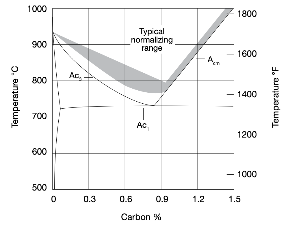
From a thermal point of view, normalizing is an austenitizing process followed by slow air cooling. Normalizing steel is carried out by heating it to approximately 30°C–50°C (54°F–70°F) above the critical Ac3 temperature — the temperature at which the transformation to a homogeneous austenitic structure is complete — and then cooling with air to room temperature.
Figure 1. Partial iron-iron carbide phase diagram showing the typical normalizing temperature range for plain carbon steel. (ASM Handbook 1991, p. 35)Figure 2. Normalizing temperature curve | Image Credit: NUTEC Bickley
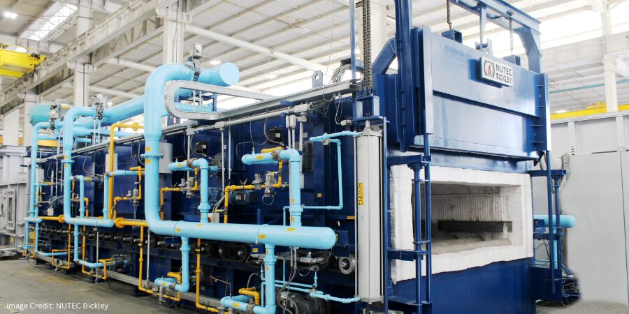
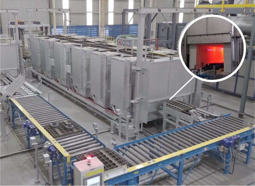
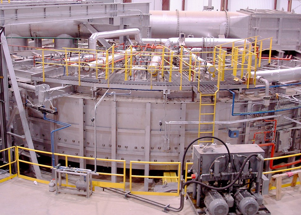
Figure 3. Example of a continuous furnace for normalizing forged parts | Image Credit: NUTEC Bickley
Why Normalize?
Reduces internal stresses after forging
Improves dimensional stability
Produces a homogeneous microstructure
Ensures a consistent structure across batches of forged parts
Helps better control potential problems in subsequent hardening or surface heat treatment processes
Isothermal Annealing
Isothermal annealing is a heat treatment applied to steels to soften their structure, improve machinability, and standardize their mechanical properties. It consists of heating the steel to the austenitizing zone — above Ac3 for hypoeutectoid steels (<0.8% carbon) and above Ac1 for eutectoid steels (≥0.8% carbon) — holding it until the desired austenite is achieved. The parts are then rapidly cooled to an isothermal temperature (usually 550°C–650°C/1020°F–1200°F) and held there until the transformation of the austenite to a fine pearlite is complete. Finally, parts are cooled in air.
It is essential to understand the isothermal transformation (IT) diagrams of the steels treated by these processes, as the ITs predict the desired microstructure after transformation, the transformation temperature, and the time required for this to occur.
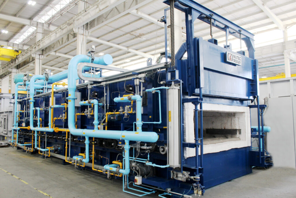
Figure 5. Example of an isothermal annealing furnace for forged parts | Image Credit: NUTEC Bickley
Main Objectives of Isothermal Annealing
The principal aim is to achieve a more homogeneous and softer structure than that obtained with conventional annealing. This helps:
To reduce internal stresses
To improve machinability and ductility
To achieve reproducible properties (by eliminating variability in the cooling rate during furnace annealing)
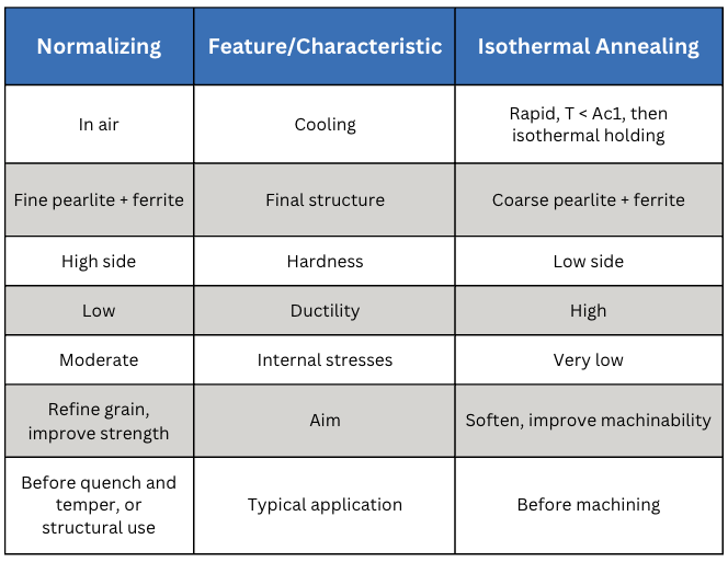
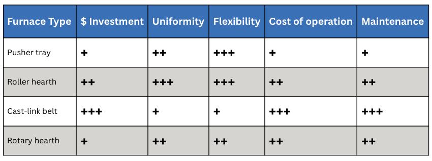
Table A. Comparative Summary — Normalizing v. Isothermal Annealing
Types of Furnace
The most typical continuous furnaces used for normalizing and isothermal annealing are as follows:
Pusher tray system
Roller hearth conveyor
Cast-link belt conveyor
Rotary hearth system
Let’s look at each one in turn and consider the advantages and disadvantages.
Pusher tray furnaces (Figure 6) offer many advantages, including a lower initial investment cost than other options. They have fewer mechanical components exposed to high temperatures requiring extensive maintenance, and the main equipment (tray pusher and puller) requires less maintenance. Short trays can be used in the direction of movement with good stability, and parts can also be loaded hung on the trays. Because the trays are closer together, the length of the furnace is shorter.
There are, however, some drawbacks. Most pusher tray furnaces only have burners firing above the load, which can affect temperature uniformity. Because of this, heating times can increase and there is less space for burners in areas of high heat demand. While main equipment maintenance is low, the trays tend to warp, resulting in additional costs. Finally, loading can be difficult and is not easily automated.
Unlike pusher tray furnaces, roller hearth furnaces (Figure 7) have burners that fire both above and below the load, making it easier to achieve uniform temperature. There is also more space for burners in areas of high heat demand. As with pusher tray furnaces, parts can also be loaded hung on trays.
In contrast, the initial investment for roller hearth furnaces is higher. There is additional maintenance due to the roller conveyor, including lubrication of bearings, chains, and roller replacement costs based on lifespan. Longer trays are also needed for good stability, increasing the furnace length.
Cast-link Belt Furnaces
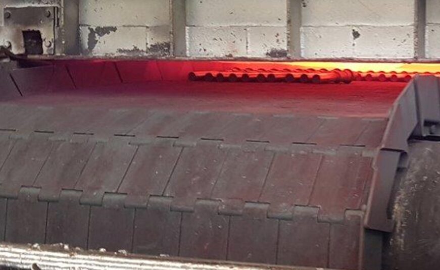
Figure 8. Cast-link belt furnace | Image Credit: NUTEC Bickley
Cast-link belt roller hearth furnaces (Figure 8) offer a simplified loading system using automation to place parts directly on the conveyor belt (with parts lying flat only) or even in bulk. The configuration also allows for shorter furnaces, distributing more load width-wise.
Conversely, there are several disadvantages, including a very high initial investment cost due to the alloy belt, along with costs associated with belt replacement. These furnaces require more energy because the belt must be reheated as it cools down on its return. They also require maintenance for the roller conveyor, bearings, chains, and the belt traction system. Like pusher tray furnaces, they only have burners firing above the load, making temperature uniformity more difficult to obtain.
Rotary hearth furnaces (Figure 9) have a moderate initial investment and carry many advantages. They allow for manual or automatic loading since parts are placed directly on the hearth (flat or in bulk), or can be loaded hung on trays using automatic loaders or robots. They occupy less floor space and have better thermal efficiency, since all the heat is directed to the product.
As with pusher tray and cast-link belt furnaces, most rotary hearth furnaces only have burners firing above the load, which can affect temperature uniformity. They typically require robots or loaders for high-volume, continuous production. While they occupy less floor space, the layout is unconventional because loading and unloading occur from the same side.
In Summary
Selecting the appropriate furnace for normalizing or isothermal annealing ultimately depends on the desired material properties, production volume, parts, and operational priorities. Each furnace type offers distinct advantages and trade-offs in terms of temperature uniformity, flexibility, maintenance, and cost, making it essential to evaluate both metallurgical requirements and practical plant constraints (Table B).
Table B. Comparative Summary
By understanding how heat treatment objectives align with furnace design — and partnering with a supplier who understands as well — you can make informed decisions to select and customize the most suitable furnace for your specific applications.
About The Author:
Arturo Arechavaleta Vice President, Metal Furnaces NUTEC Bickley
Arturo Arechavaleta, VP of Metal Furnaces at NUTEC Bickley, is a mechanical and electrical engineer (AA) and holds an MBA. He has 35 years of experience in the furnace industry, including the field of engineering, working on challenging projects, leading multidisciplinary teams, and managing business units.
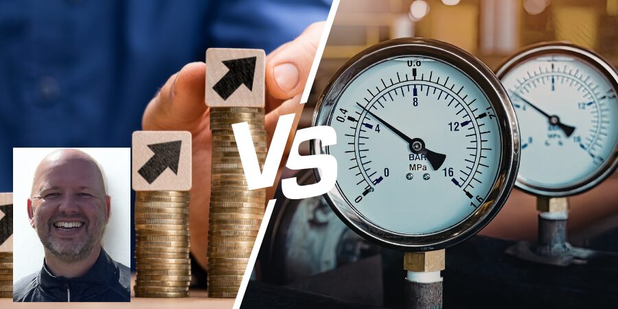
What’s the real price of a leak test system? According to Norbert Palenstijn of Nolek, it’s not the number on the invoice. In this guest column, he walks through why total cost of ownership — spanning calibration, consumables, throughput, and quality impact — should drive purchasing decisions more than CapEx alone.
When a factory considers new capital equipment, the first question almost always sounds the same: “What’s the CapEx?”
It is an understandable starting point. Capital expenditure is big, visible, and easy to compare. Numbers sit neatly in a column, budgets are allocated, and decisions get made. But if we stop there, especially when it comes to leak testing equipment, we risk seeing only half the picture.
Leak testing has one main role in production: it is a sorting function. Its job is to distinguish between good and bad parts based on a leak specification. That means it is not just a machine — it is the gatekeeper of quality. And for a gatekeeper, what matters most is not just the cost of admission, but how reliably the gate opens and closes.
The Hidden Cost of “Lower Purchase Price”
Imagine two leak test systems on the factory floor. One has a lower CapEx and looks attractive on paper. But in practice, it requires more frequent calibrations, eats through consumables, and delivers an uncomfortable number of false rejects. Every false reject creates rework and lost time. Every misclassified “pass” creates a risk that defective parts slip through. Suddenly, the lower cost option does not feel so appealing anymore.
Now compare it to a system with a higher upfront price but stable measurement performance, longer service intervals, and better correlation to the specification. Over years of production, this system quietly saves money and protects reputation, even if the original CapEx line was higher.
Beyond the Purchase Price
Image Credit: @TarikVision/AdobeStock
Focusing only on CapEx is like buying a sailboat and budgeting for the hull, but forgetting sails, navigation equipment, and upkeep. The hull might look affordable, but the true cost of ownership is what keeps the ship sailing safely across oceans.
In leak testing, the total cost of ownership (TCO) includes:
Purchase and installation (CapEx)
Calibration, service, and downtime (OpEx)
Consumables and spare parts
Impact on throughput (cycle times, operator time)
Impact on quality (false rejects and escapes)
These factors flow directly into cash flow, customer satisfaction, and brand reputation.
The Real Measure of Value
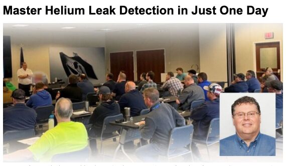
Learn the fundamentals of helium leak detection firsthand at Heat TreatToday’s Leak Detection Seminars. Click the image above to register for a session near you.
Leak test systems do not just live on balance sheets, they live in production lines. Their value is measured not just in cost, but in confidence:
Confidence that every part has been tested against specification
Confidence that defects are caught before they leave the factory
Confidence that customers can trust what you ship
That’s why a decision made only on CapEx is incomplete. A leak test system is a long-term partner in your production process. It is not just a one-time payment, it is what you pay and gain every day it runs.
Closing Thoughts
When considering new leak testing equipment, do not just ask, “What is the CapEx?” Ask instead:
What will it cost me to run?
What will it cost me if it fails to sort correctly?
What confidence does it provide in every product leaving my site?
Because in the end, the true price of a leak test system is not the invoice you pay at purchase. It is the trust it secures, or fails to secure, for years to come.
About The Author:
Norbert Palenstijn U.S. Brand Manager Nolek|VES|ALPHR|Natgraph
Norbert Palenstijn has built a career as a recognized specialist in helium and hydrogen leak detection, with over 26 years of dedicated experience in industrial vacuum systems, industrial leak testing and detection, and advanced engineering solutions.
Ask The Heat Treat Doctor® has returned to bring sage advice to Heat Treat Today readers, answer questions about heat treating, brazing, sintering, and other types of thermal treatments, as well as metallurgy, equipment, and process-related issues. In this installment, Dan Herring examines the devastating effects of hot gaseous corrosion on furnace alloys: exploring the mechanisms behind metal dusting, the gas-solid reactions that drive catastrophic carburization, and the mitigation strategies to extend the life of heat treaters’ most valuable furnace components.
This informative piece was first released in Heat Treat Today’sJanuary 2026 Annual Technologies To Watch print edition.
Have questions or feedback? We’d love to hear from you — reach out to our editorial team at editor@heattreattoday.com.
Corrosion is a concern experienced by everyone involved in manufacturing industrial products. While there is a plethora of data and information on the effects of corrosion on engineered materials available (sources provided in the references section of this column), most corrosion engineers are focused on aqueous corrosion. By contrast, heat treaters must understand the effects of hot gaseous corrosion, especially on our furnace alloys. Let’s learn more.
Corrosion Basics
It is important to understand that all materials are chemically unstable in some environments and corrosive attack will always occur. In the scientific world, it can often be modeled and its effects predicted by studying thermodynamic data and knowing which of the many corrosion-related chemical states are active. In our world, however, it is equally important to understand the various forms of corrosion, namely:
Dezincification (aka selective leaching)
Electrolytic
Erosion
Galvanic (or two metal) action
General (aka uniform) attack
Intergranular attack
Pitting
Stress corrosion
The greater the metal’s solubility, the greater the degree and severity of the corrosive attack. There are many important variations of these forms of corrosion; two of the most important are 1) localized corrosive attack (e.g. pits, intergranular attack, crevices) and 2) interaction with mechanical influences (e.g., stress, fatigue, fretting). These actions are frequently rapid and have catastrophic effects.
The number of ways to combat corrosion have been well-documented, including alloying to produce better corrosion resistance materials; cathodic protection (via sacrificial anodes); coatings (metallic or inorganic); organic coatings (e.g. paints); metal purification; alteration of the environment; and nonmetallic or design (i.e., physical) changes.
Heat Resistant Alloys
Furnace interiors contain numerous examples of heat-resistant nickel-chromium-iron (Ni-Cr-Fe) alloys, including radiant tubes, fans, heating elements, roller rails and rollers, thermocouple protection tubes, chain guides, and atmosphere inlet tubes, to name a few. Baskets, grids, and fixtures are other examples. These alloys are normally selected based on their strength (at temperature) rather than resistance to corrosive attack.
Since these heat-resistant alloy parts are often the most expensive furnace components, heat treaters must understand how they can be attacked and what can be done to extend their life by minimizing or preventing corrosion.
Gas-Solid Reactions
A chemical reaction involving a (non-equilibrium) gas or gas mixture and a solid is classified as a gas-solid reaction. Examples of intermediate and high temperature reactions of this type include oxidation, sulfidation, carburization, and nitriding. Effects of gases containing vapors of chlorine, fluorine, and effluents from deposits of various alkaline chemicals (from cleaning compounds) and even phosphates are also problematic. The principles are the same for all types — only the details differ. As heat treaters, our interest is in controlling, retarding, or suppressing these reactions to prevent unwanted corrosion, gasification, or embrittlement of the furnace alloy or materials being processed.
Examples of Catastrophic Carburization (a.k.a. Metal Dusting)
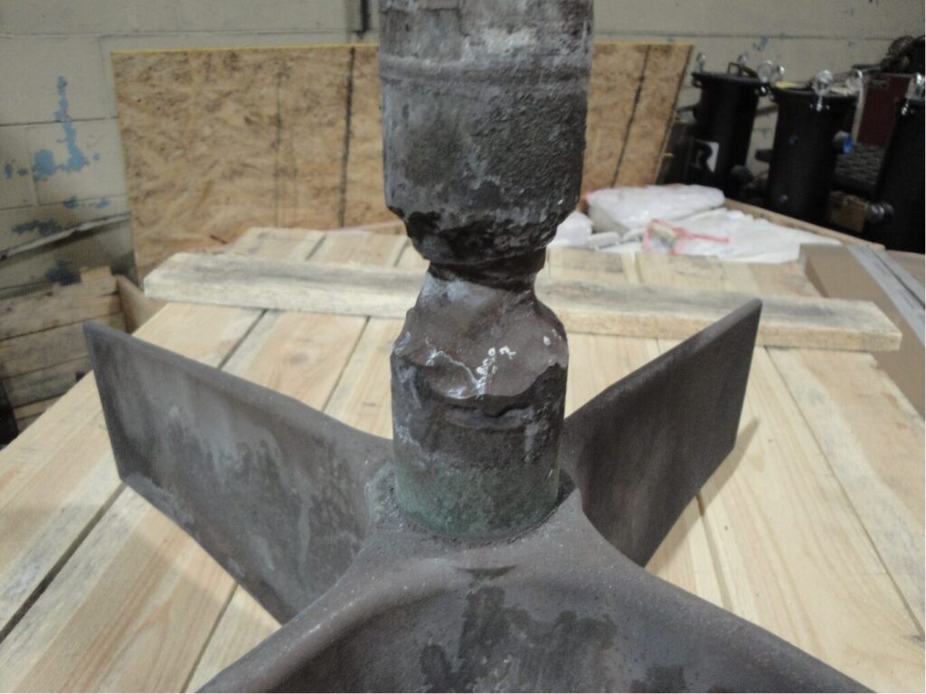
Figure 1. Pusher furnace alloy fan and shaft assembly | Image Credit: The Heat Treat Doctor®
Metal dusting (Figure 1) is a hot gaseous corrosion phenomenon in which a metallic component disintegrates into a dust of fine metal and metal oxide particles mixed with carbon.
Generally, metal dusting occurs in a localized area, and how rapidly the disintegration progresses is a function of temperature, the composition of the atmosphere and its carbon potential, and the material. Other significant factors include the geometry of the system, reaction kinetics, diffusivities of alloy components, the specific-volume ratio of new and old phases, and the ultimate plastic strain.
Metal dusting usually manifests itself as pits or grooves on the surface, or as an overall surface attack in which the metal can literally be eaten away in a matter of days, weeks, or months. As an example, this writer has seen a 330-alloy plate mounted underneath a refractory-lined inner door of an integral quench furnace (where atmosphere passes underneath the door and into the quench vestibule) reduced in thickness from 12.5 mm (0.50 in) to less than 0.75 mm (0.03 in) in a little over two months.
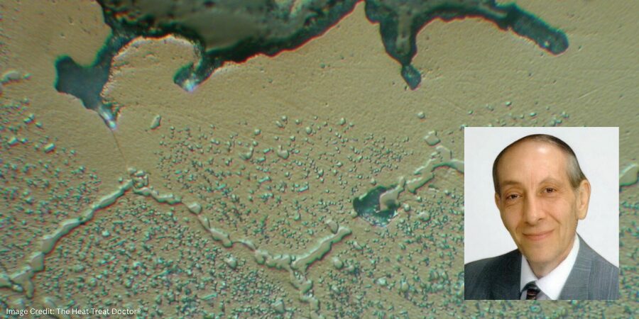
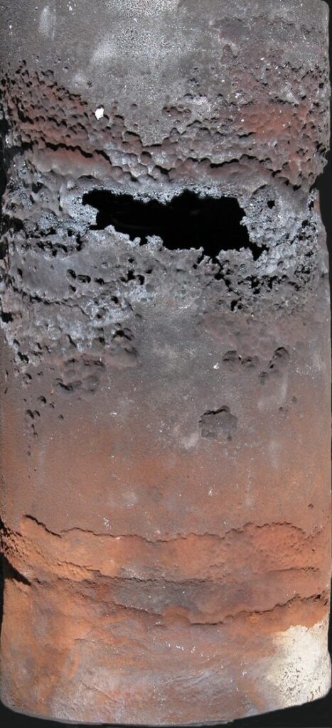
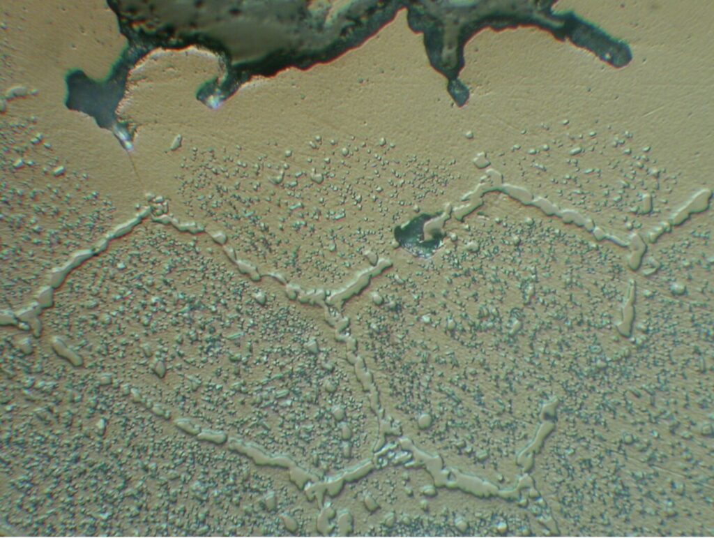
Figure 2. 330 alloy radiant tube removed after six months of use (rotary retort furnace) | Image Credit: The Heat Treat Doctor®Figure 3. Microstructural view: catastrophic carburization | Image Credit: The Heat Treat Doctor®
In another example, a metallographic investigation performed by this writer on a failed wrought 330 alloy radiant tube (Figure 2) was conducted. Optical microscopy of the inside (Figure 3) and outside diameter surfaces in the attacked area revealed evidence of massive carbides. These carbides are formed by the reaction of carbon with chromium, depleting the matrix of chromium in regions adjacent to the carbides. Grain detachment and subsequent failure by erosion then occurred.
How Does It Occur?
In general, catastrophic carburization of ferrous alloys proceeds via the formation and subsequent disintegration of metastable carbide. The first step in the process is absorption of the gaseous phase on the surface of the metal; the more reactive this phase, the easier it decomposes or is catalytically decomposed (in the case of iron) on the surface. This step is followed by diffusion of carbon atoms from the surface into the bulk metal.
As a result, there is a continuous buildup of carbon within the surface layer. As this layer becomes saturated with carbon, a stable carbide, metastable carbide, or an active carbide complex forms, which then grows until it reaches a state of thermodynamic instability, at which point it rapidly breaks down into the metal plus free carbon.
It’s at this stage that the metal disintegrates to a powder as the result of plastic deformation and subsequent fracture in the near-surface layer. The process is controlled by internal stresses due to phase transformation; in other words, competition between stress generation and relaxation exceeds the ultimate strength in this near-surface layer and causes fracture to occur.
In Ni-Cr-Fe alloys, the phenomenon occurs slower (but does not stop) since the disintegration leads to larger metal particles, which are less active catalysts for carbon deposition than the fine iron particles that form with ferrous metals. Therefore, the mass gain from carbon depositing onto high-nickel alloys is much lower. Also, the decomposition of high-nickel alloys occurs by graphitization and not via unstable carbides.
Pourbaix-Ellingham Diagrams
Thermodynamics can be applied to solid-gas reactions to obtain equilibrium dissociation pressures below which no reactions occur. Data and diagrams are available for the free energies of formation versus temperature for most metallic compounds. An interesting use of Pourbaix diagrams (generally reserved for mapping out possible stable equilibrium phases of an aqueous electrochemical system) as a predictor of stable alloy systems is found by superimposing the various elemental constituents. These diagrams are read much like a standard phase diagram (with a different set of axes).
In Summary
Hot gaseous corrosion should be an area of focus for every heat treater to extend the life of alloy components, reduce downtime, and save money. Mitigation in the form of alloy selection, equipment design, type of atmosphere, process/cycle selection, and idling temperatures will play a huge role in extending the life of our furnace alloys, baskets, and fixtures.
References
ASM International. 1971. Oxidation of Metals and Alloys.
Nateson, K. 1980. Corrosion–Erosion Behavior in Metals. Warrendale, PA: Metallurgical Society of AIME.
National Bureau of Standards. 1978. Gas Corrosion of Metals.
Pourbaix, Marcel. 1974. Atlas of Chemical and Electrochemical Equilibria in Aqueous Solutions. Houston, TX: NACE International.
Pourbaix, Marcel. 1998. Atlas of Chemical and Electrochemical Equilibria in the Presence of a Gaseous Phase. Houston, TX: NACE International.
Schweitzer, Philip A. 1996. Corrosion Engineering Handbook. New York: Marcel Dekker.
Staehle, R. W. 1995. “Engineering with Advanced and New Materials.” Materials Science and Engineering A 198 (1–2): 245–56.
Stempco, Michael J. 2011. “The Ellingham Diagram: How to Use It in Heat-Treat-Process Atmosphere Troubleshooting.” Industrial Heating, April.
Uhlig, Hubert H. 2008. Corrosion and Corrosion Control. Hoboken, NJ: Wiley-Interscience.
Fabian, R., ed. 1993. Vacuum Technology: Practical Heat Treating and Brazing. Materials Park, OH: ASM International.
The Boeing Company. n.d. “Practical Vacuum Systems Design Course.”
About the Author
Dan Herring “The Heat Treat Doctor” The HERRING GROUP, Inc.
Dan Herring has been in the industry for over 50 years and has gained vast experience in fields that include materials science, engineering, metallurgy, new product research, and many other areas. He is the author of six books and over 700 technical articles.