Ask The Heat Treat Doctor® has returned to bring sage advice to Heat Treat Today readers and to answer your questions about heat treating, brazing, sintering, and other types of thermal treatments as well as questions on metallurgy, equipment, and process-related issues.
This informative piece was first released in Heat Treat Today’sNovember 2025 Annual Vacuum Heat Treating print edition.
Case depth, case uniformity, and final mechanical (as well as other) properties rely not only on controlling both equipment and process variability during heat treatment, but on having clean, properly prepared part surfaces prior to and during heat treating. Expert Dan Herring encourages to learn more below.
Case hardening is a thermochemical surface treatment process designed to add a particular element or combination of elements to a material such as steel. Familiar examples include carbon (carburizing); carbon and nitrogen (carbonitriding); boron (boriding); nitrogen (nitriding); and nitrogen and carbon (nitrocarburizing — ferritic or austenitic). These processes are typically designed to increase the near surface hardness of steel after quenching.
However, various problems can arise due to either the materials or the manufacturing methods employed prior to or during heat treating that will retard or prevent absorption and/or diffusion of the desired element(s) during heat treating. Some of the metallurgical consequences can include:
Shallow or uneven case depths
Surface oxidation
Intergranular oxidation or decarburization
High levels of retained austenite
Soft spots due to incomplete hardening
Machine-Induced Surface Conditions
Improper machining prior to case hardening can compromise surface integrity. Tooling choices, improperly maintained equipment, inadequate operator training, and even environmental factors can contribute to a variety of issues.
While machining problems occur frequently, they are mostly preventable. Attention to part surface condition, cleanliness, and mechanical integrity is essential before heat treating. Training, standardizing machining protocols, planned preventative maintenance programs, and part inspection prior to heat treating will help avoid these issues. Consult Table A for further details on how the causes and effects of undesirable machine-induced surface conditions can be solved.
Splatter of Stop-off Paints on Unintended Areas
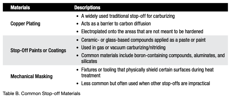
A material that masks the surface of steel and delays or prevents case hardening is called a stop-off or maskant. These materials are applied to specific areas of a steel part to prevent the diffusion of hardening elements (like carbon or nitrogen) into the surface during case hardening processes, such as carburizing, nitriding, or carbonitriding. (See Table B.)
Enriching Gas Additions (Sooting)
During the carburizing or carbonitriding process, it is not uncommon to develop a layer of soot on the surface of the parts, especially if the enriching gas additions begin before the entire load is uniformly up to temperature. In some instances, the amount of soot formation is such that the case depth or uniformity is affected. This is often difficult to diagnose, as the soot layer “washes off” during quenching in a liquid, and the part surfaces come out of the furnace looking reasonably clean.
Material-Related Issues
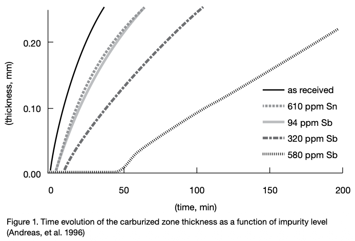
The use of scrap in steelmaking, especially for low alloy case hardening steels can lead to a relatively high level of impurities and tramp elements. At high temperatures these impurities tend to segregate at grain boundaries and migrate toward the surface. This type of segregation can retard case hardening by impeding element (e.g., carbon) transfer. For example, the effects of tin (Sn) and antimony (Sb) on the kinetics of carburization are particularly problematic (Figure 1).
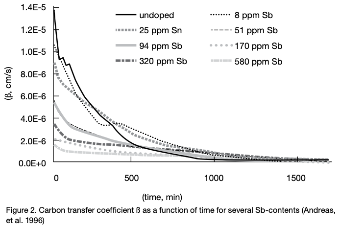
The effect of tramp elements on retardation of carburization can be expressed in the following order (Andreas, et al. 1996), namely Sb > Sn > P > Cu > Pb. To see the effect of one such element, the carbon transfer coefficient (ß) for typical commercial steels is shown as a function of antimony (Sb) content (Figure 2).
In Summary
These are a few of the many causes delaying or preventing case hardening from being effective. There are many others, including alkaline cleaning compounds (in too high a concentration) and even phosphate and other drawing lubricants used in the manufacture of fasteners. Inspection and cleaning of the part surface prior to case hardening will avoid many of these issues. Reviewing material certification sheets for elements known to interfere with case hardening is also an effective way to anticipate problems with case hardening.
References
Herring, Daniel H. 2014. Atmosphere Heat Treatment, Volume 1. Troy, MI: BNP Media.
Herring, Daniel H. 2015. Atmosphere Heat Treatment, Volume 2. Troy, MI: BNP Media.
Ruck, Andreas, Monceau, Daniel, and Grabke, Hans Jürgen. 1996. “Effects of Tramp Elements Cu, P, Pb, Sb, and Sn on the Kinetics of Carburization of Case Hardened Steels.” Steel Research 67 (6): 242–48.
About the Author
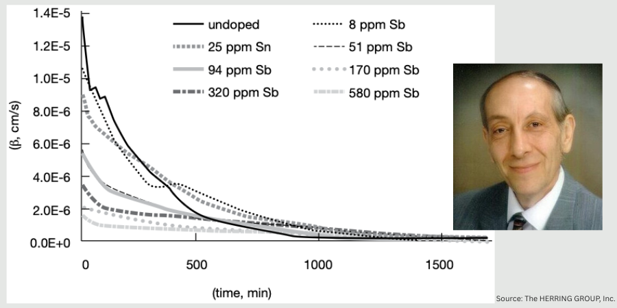
Dan Herring “The Heat Treat Doctor” The HERRING GROUP, Inc.
Dan Herring has been in the industry for over 50 years and has gained vast experience in fields that include materials science, engineering, metallurgy, new product research, and many other areas. He is the author of six books and over 700 technical articles.
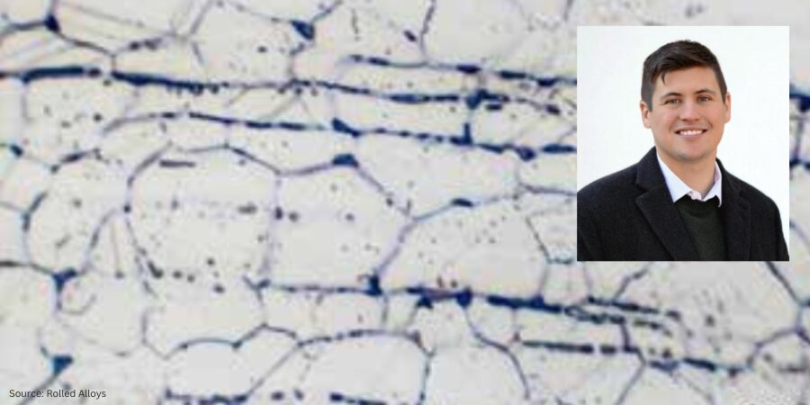
In this Technical Tuesday installment, Nick Hicks, metallurgical services manager at Rolled Alloys, emphasizes the importance of mastering the basics of sigma phase metallography in stainless steels. Understanding these fundamentals helps you know when to consult a metallurgist and guarantee top performance of heat treated parts.
This informative piece was first released inHeat Treat Today’sNovember 2025 Annual Vacuum Heat Treating print edition.
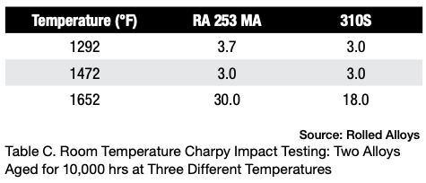
Heat treaters are always seeking new methods of heat treat and new alloys to improve performance at a lower cost. In the world of stainless steel, there are well-known choices like 310 and newer options like RA 253 MA®. These alloys have exceptional qualities, especially RA 253 MA, which has creep strength up to 2000°F and oxidation resistance up to 2000°F. However, heat treaters should be aware of a potential issue when using such alloys: the formation of sigma phase over time.
In some cases, premature wear in nickel alloys was attributed to sigma phase embrittlement, but it’s important to note that sigma phase does not actually precipitate in nickel alloys. Instead, the actual microstructure may exhibit grain boundary oxidation or carbides. This article seeks to provide a clearer understanding of sigma phase metallography and its impact on stainless steels.
Definition of Sigma Phase
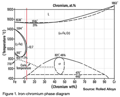
Sigma phase is an intermetallic compound made up of chromium and iron. It is hard, brittle, and non-magnetic. At room temperature, the presence of sigma phase can make the material so brittle that a sudden, hard impact can shatter a piece of metal that contains it, similar to a piece of glass. Pure sigma phase forms when the chromium content is between 42% and 50%, and it is one of the equilibrium phases in the iron-chromium phase diagram as seen in Figure 1.
The peak temperature for sigma phase formation in a 46% Cr alloy is 1510°F. A literature review reveals that different sources cite varying temperature ranges for sigma phase formation. This variation is due to each alloy having its own unique sigma formation range. According to one expert (Kelly 2005), sigma phase can form in the temperature range of 1100°F–1600°F (590°C–870°C).
Metallurgy of Sigma Phase
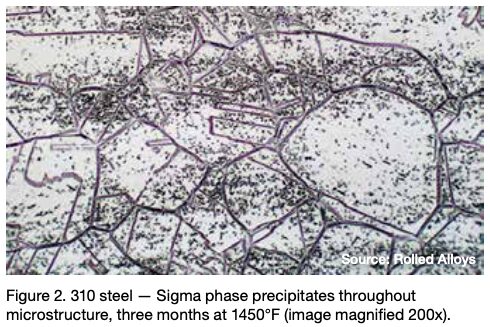
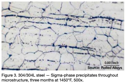
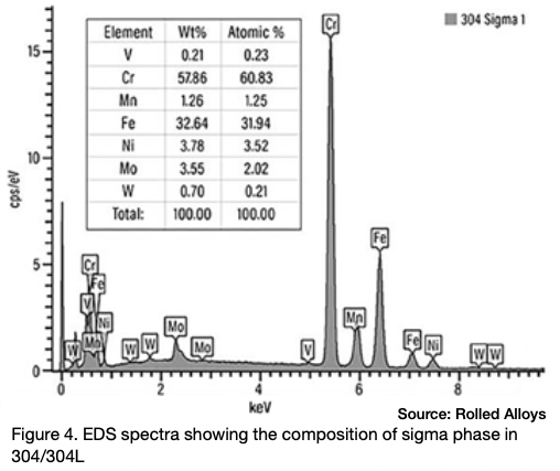
Many engineers require assistance in distinguishing between sigma phase and the formation of grain boundary oxides and carbides. Otherwise, they might reach incorrect conclusions. Sigma phase is a precipitation product that can manifest in both individual grains and along grain boundaries. Examples of sigma phase formation can be observed in Figures 2–4.
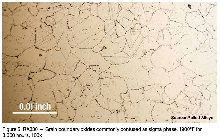
When observing nickel and certain nickel alloys like RA330®, confusion can arise due to the presence of grain boundary oxidation or carbide formation. These occurrences are often mistaken for sigma phase formation by engineers, but it’s important to note that a nominal nickel content of at least 35% is sufficient to prevent sigma phase formation.
Figure 5 depicts RA330 after a 3,000-hour duration at 1900°F. Despite 1900°F being significantly higher than the sigma formation range, some engineers determined that the grain boundary oxides were sigma phase. When there is any uncertainty, it is advisable to consult with a metallurgist who is knowledgeable about the metallography of these alloys.
Physical Properties of Material with and without Sigma Phase
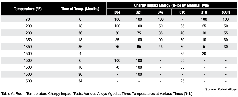
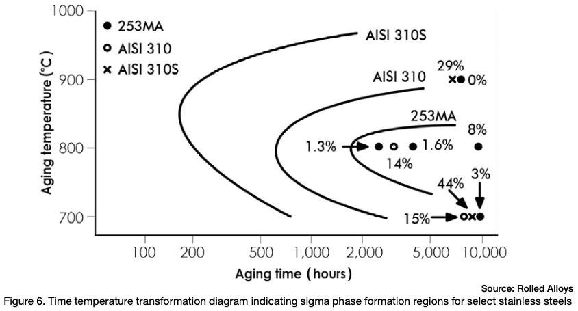
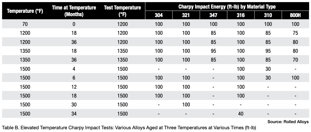
Table A displays the results of impact testing for six different alloys aged at three different temperatures for varying durations. All the alloys experienced some degree of deterioration over time, with certain alloys showing significant losses and reduced ductility. Further analysis revealed that each alloy has its own specific temperature at which sigma phase formation occurs most rapidly. In fact, the formation of sigma phase is dependent on the time at temperature, which makes a C-type curve.
Figure 6 depicts the time temperature transformation curves for sigma phase formation for a few different stainless steels. Any point past a specific alloy’s curve results in the formation of sigma phase.
The results of elevated temperature impact testing for six alloys are presented in Table B. Many of the values in the table indicate that these alloys generally show either no loss of ductility or significantly less loss of ductility when the testing is carried out at elevated temperatures. In most cases, the materials still exhibit sufficient ductility to be safely used at these temperatures.
When these alloys have formed sigma phase and then cooled to room temperature, it’s important to prevent any kind of impact. At operating or heat treating temperatures, these alloys generally maintain enough ductility to be safely used.
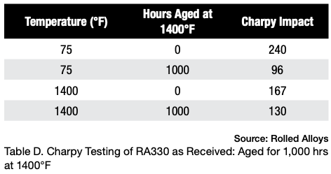
Table D displays the results of Charpy testing conducted on RA330 after aging. Although there is a slight decrease in ductility, the material still exhibits sufficient energy absorption to be considered quite ductile and safe for use at room temperature.
Conclusion
Sigma phase precipitation is a phenomenon that occurs in stainless steels and alloys containing less than 35% nominal nickel content. This does not occur in nickel alloys with 35% nickel or more. Sigma phase can make materials very brittle at room temperature. However, at elevated temperatures within typical heat treating ranges, most materials retain sufficient toughness to be used without any concern. It’s important to note that even at high temperatures, toughness is lost. More caution should be exercised in choosing alloys for vibrating systems, as constant vibration can cause premature failure if sigma phase has formed.
Engineers may mistakenly identify grain boundary oxidation or carbides as sigma phase formation in alloys that do not actually form sigma phase. To ensure accurate conclusions, it is important to have interpretations verified by experienced metallurgists who are familiar with the metallography of stainless steels and nickel alloys.
An understanding of the basics of sigma phase metallurgy in stainless steels will help the heat treater, manufacturer, and end user avoid failures associated with sigma phase embrittlement.
References
Andersson, Thomas, and Thomas Odelstam. 1984. Sandvik 253MA (UNS S30815) – The Problem Solver for High Temperature Applications. Sandviken, Sweden: R&D Centre AB Sandvik Steel Bulletin, October.
Lien, George E. 1968. Behavior of Superheater Alloys in High Temperature, High Pressure Steam. New York, NY: The American Society of Mechanical Engineers.
Nick Hicks Metallurgical Services Manager Rolled Alloys
Nick Hicks is the metallurgical services manager at Rolled Alloys. He holds a bachelor’s degree in mechanical engineering from the University of Toledo and a master’s degree in materials science from Worcester Polytechnic Institute. Nick represents Rolled Alloys at organizations such as the Materials Technology Institute (MTI) and the American Society for Testing and Materials (ASTM). He is also a former Emerging Professional on the ASM Heat Treat Board. Nick specializes in stainless steel and nickel alloy metallurgy for high-temperature and corrosion-resistant applications.
In this episode of Heat TreatRadio, host Doug Glenn invites Dennis Beauchesne of ECM USA to explore the technology, benefits, scalability, and sustainability of modular heat treating systems. Together, they discuss how shared utilities, automated transfers, and adaptable heating cells can replace multiple standalone furnaces without compromising quality or precision. Learn how these systems streamline and simplify operations for future expansion — one cell at a time.
Below, you can watch the video, listen to the podcast by clicking on the audio play button, or read an edited transcript.
The following transcript has been edited for your reading enjoyment.
Introduction
Doug Glenn: I am very privileged to have with me today, Dennis Beauchesne from ECM USA. We’re going to be talking about modular heat treating systems, which is a growing category of equipment.
ECM Synergy Center (00:50)
Doug Glenn: Tell me about ECM’s Synergy Center, which is where you are at right now, on the shop floor.
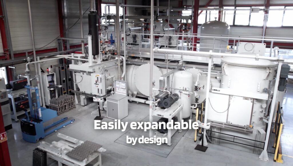
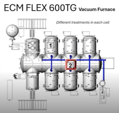
The ECM Flex 600TG vacuum furnace located in the ECM Synergy Center Source: ECM USA
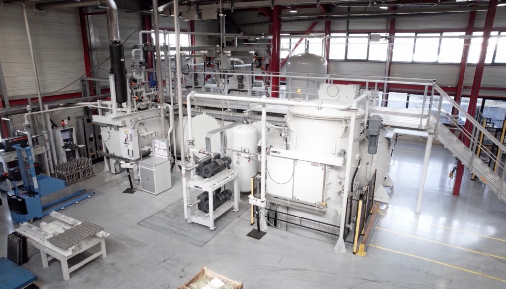
Dennis Beauchesne: I’m standing here in the middle of our Synergy Center. It’s about a 5,000-square-foot facility that is dedicated to proving out client parts for testing various processes, mostly LPC, but we also do a number of other processes here. We have a full metallurgical lab, 3D microscope, a number of tools, including a CMM that we can do before and after heat treat distortion testing for clients that want to know how much their parts move.
It’s a dedicated center just for clients to use. We also use the center for pre-completion of installations, final testing, and training, such as training on maintenance, understanding the software, and how everything works together.
Doug Glenn: It’s proof of process plus much more — helping clients’ proof of process.
Dennis Beauchesne: Absolutely. That’s a big part of convincing people that this process is for them and that it works on their part. We can send them ten different reports of an exact same material and part, but they want to know what their part will do.
What is Modular Heat Treating? (02:50)
Doug Glenn: On a very basic, rudimentary level, what is modular heat treating and how does it differ from what might be considered standard or normal heat treating?
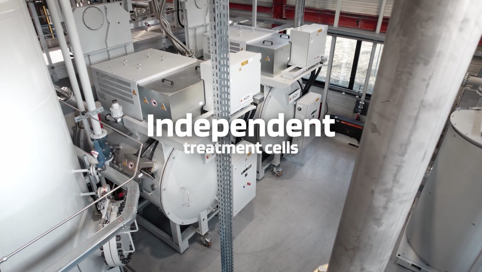
Dennis Beauchesne: A modular heat treat system is one that works together to have more than one furnace working in the same platform. You may have a shop that has five or six vacuum furnaces separated — they each have their own door, vacuum system, electrical supply, quench motors…those types of components. Or you may have a series of batch IQ furnaces for carburizing; those systems are one off, which means they are individual, independent systems.
In a modular system, you try to utilize those facilities for the use of multiple heating chambers. Instead of having one vacuum furnace with one set of pumps and one gas quench motor, what we would do is have three to eight heating cells that would be utilizing one quench, depending on the process timing; that’s all done with an internal transfer car and we try to utilize one vacuum system. It’s much smaller than what you would have for three, four, or even eight cells.
If you had oil or high pressure gas quenching, which is what’s dominating right now in the modular heat treat business, you could supply basically six batch IQ hot zones to one oil quench.
The savings then are huge simply by removing five or six other quench tanks in front of this system, as well as leveraging the floor space (and the number of pits you have to dig). Other advantages including utility savings and utilizing equipment across a number of heating chambers.
Doug Glenn: This modular approach is basically separate chambers that are dedicated to doing whatever that chamber is doing, and they are all in some way interconnected. For standard units, you would heat up, pre-process, do the actual process itself, cool down, all in the same chamber. In a modular unit, you move from chamber to chamber to do each of those separate steps.
Dennis Beauchesne: Yes, I refer to it as a continuous batch.
Doug Glenn: Continuous batch. We were talking before we actually hit the record button with your colleague there, Allison DeAngelo, who just got done visiting the Heat Treat Boot Camp. We were talking about different types of furnaces, and we started talking about continuous vacuum, which of course, is almost a misnomer — a vacuum can’t be continuous because you have to open it up and break the vacuum to get stuff out. Anyhow, we talked about it basically being a batch, right? A batch furnace that’s continuous, a continuous batch furnace.
Benefits of Modular Heat Treating (06:35)
Now that we have a basic understanding of what these modular systems are, why would companies want to move from the standard type of heat treating system to a modular system?
Dennis Beauchesne: Manpower. If you are running five or six vacuum furnaces, you are going to need a number of people to open the doors, put new loads in, those kinds of tasks. With a modular system, you only have one entry or one exit area. Therefore, you are only going to load once every 15-20 minutes, and the system is going to take over and control that load going through the system.
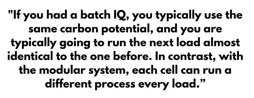
In addition, especially in a carburizing atmosphere situation, you can have every load be a different case depth — a different process in each cell — and then the next load that goes in that same cell can be totally different from the one before. For instance, if you had a batch IQ, you typically use the same carbon potential, and you are typically going to run the next load almost identical to the one before. In contrast, with the modular system, each cell can run a different process every load.
It’s also easier to integrate automation if you are doing capacity increases.
Throughput Comparison (08:00)
Doug Glenn: What is the comparison of throughput between a standard unit and a modular unit?
Dennis Beauchesne: The throughput comparison is interesting because you typically can use a little higher temperature for a carburizing and a little higher carbon potential, and of course that’s what we specialize in here with the modular systems. You can achieve about a 30-40% gain in your cycle time. That furnace is operating very close to 100% occupancy, because when that load is done, you are moving it out right into the gas quench. Then, the next load comes and goes right into it.
Doug Glenn: You are able to increase your throughput because you have basically 100% utilization of the equipment or very close to that. Comparatively, you don’t necessarily have that in the standard equipment.
Product Quality Comparison (09:15)
Doug Glenn: Do modular systems produce higher quality products?
Dennis Beauchesne: The quality of the parts coming out of the system is improved. A vacuum environment is a very clean environment, especially if we are considering atmosphere and low pressure carburizing — it’s in a vacuum. We typically do everything in high pressure gas quenching. However, even in oil quenching under vacuum, you are going to have a much cleaner part.
Also in low pressure carburizing, the carburizing is much more uniform throughout the part because we heat it to temperature under nitrogen before the part gets to austenitizing temperature to start attracting carbon. We make sure that the full part, that’s the tooth, the root, every piece of the part, is at temperature before we start adding carbon to the load, which makes a more uniform case depth, and therefore makes a stronger part.
Doug Glenn: Since each module, each chamber, is dedicated to doing what it is supposed to do, it seems like the consistency and the reliability of the parts being processed in a modular system have a much better chance of being higher quality.
Dennis Beauchesne: You do not have six different variable chambers or six different variable systems. You just have to look at monitoring the connection between those and understanding that the vacuum levels are all the same across the levels and across the cells. Each cell can meet a different temperature and run a different process, but those are consistent across the board.
Typical Dedicated Cells/Chambers (11:10)
Doug Glenn: What would be the typical dedicated cells/chambers of a modular system?
Dennis Beauchesne: It is dependent on the processes. They are most widely used for vacuum carburizing. For pre-oxidation and preheating, we usually use an air oven outside of the system, and we connect that with an external loader. Before the load goes into the modular system, the load will go through a regular air oven, be heated to around 700°F (400°C), and then the load will be moved in.
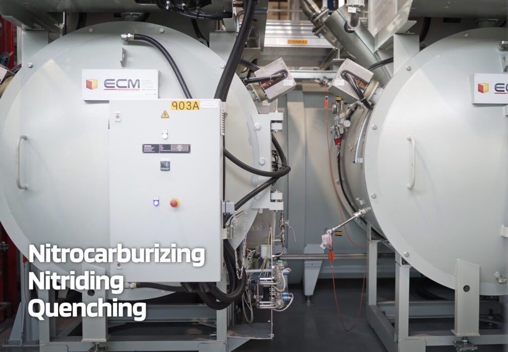
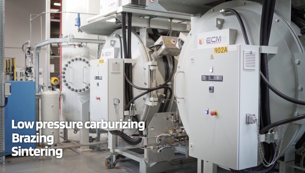
For sintering and those kinds of applications, there is a debind step or a preheat step that would be done in one cell. Some of the processes that can be done in a modular system include:
Low pressure carburizing
Low pressure carbon nitriding (LPC)
FNC (ferritic nitrocarburizing)
Nitriding
Debinding
Sintering
Neutral hardening
The most prominent process right now is LPC, and that is being used all over the world in these systems.
Advantages of a Modular Unit for Captive Heat Treaters (12:53)
Doug Glenn: Why would a modular unit be beneficial for a captive heat treater, someone who does their own in-house heat treating, which probably means they’ve got potentially high volume, low variability as far as their workloads?
Dennis Beauchesne: The modular unit has many different advantages. First of all, floor space. You are going to save a lot of floor space by not having multiple furnaces set up separately. You will also save utilities because you would not have as many vacuum pumps or electrical systems running these furnaces on their own. You will have some shared service and utilities in that fashion.
Doug Glenn: That would also likely lead to maintenance cost savings as well, correct?
Dennis Beauchesne: Yes, it all goes down the line. Anything that you have multiples of, you are going to have much less costs than on a joint system. The modular system might be a little larger than one singular unit, but there will be fewer of them.
For vacuum carburizing applications in a captive shop, the quality and cleanliness of the part is very, very important. Gas quenching lends itself to no oil in your plant, no washers necessary for a post-quench. Typically, there’s a washer before the process starts, but you do not have to have any wash to get the oil off of the parts with a modular unit — you do not have to reclaim the oil or the water from the washer. You would not have waste oil in your plant either or any oil on your plant floor. These are some of the reasons some of the larger captive shops have gone to the modular systems.
Also, safety: There are no open flames with a modular unit, no risks of fire on the systems. They are also easier to maintain. For a fully operational, let’s say, eight-cell system for high production, captive operation, it would only take about five hours to cool that whole system down if you had to go in and work on the whole system. In comparison, it’s going to take you three to four days sometimes to cool down a typical atmosphere, high-temperature furnace.
It also takes time to heat the system up again. In a modular system, it takes about an hour and a half to heat the system up again and then you are ready to start running. That means now you can schedule your downtime on weekends or holidays. You do not have to have staff present to run anything.
You also do not have to have a secondary equipment, like Endo generators running to feed the carburizing gas. The carburizing gas is using acetylene out of cylinders, it’s not a regenerative system. You do not need a separate piece of equipment to feed to the furnace.
Another benefit is CapEx expansion. Typically, captive heat treaters do not want to buy everything upfront because their volumes are going to increase over time. In the beginning, they typically only need one or two cells ready to do a small amount of production so they can prove out the production and prove out the system. Then they can start building the system with more cells and more capacity later on. Generally, it’s two to three days of downtime to add a cell to a system. It’s very convenient to do that with a modular system. All of the utilities are typically alongside the modular system so that you can easily add those or add a cell to it over a short period of time, and those cells can be ordered a year or two down the road whenever you might need that.
You also can order peripheral equipment, like extra temper ovens or additional automation. You can add a robotics system to the layout as well. That’s why captive shops are very interested.
Finally, workforce: It’s a little bit easier to get someone to work on a modular system. These systems are completely clean and white. The one located in our Synergy Center has been there for eight years. We use it every single day, and it’s a very clean aesthetic environment for someone to work in. These systems are also water cooled, which means not a lot of extra heat in the building around you to work in.
Advantages of a Modular Unit for Commercial Heat Treaters (17:59)
Doug Glenn: What are some advantages of modular units for commercial heat treating?
Dennis Beauchesne: On the commercial heat treat side, modular units are typically useful because you can get multiple processes out of similar cells and you can have a system that has oil and a gas quench.
You can have a lot of flexibility in that one system that you have in the plant. I’ve visited hundreds of captive and commercial heat treaters. They generally have a number of furnaces in one area of the plant, and a number of furnaces in another area of the plant. A modular system gives you all the capability in one machine and one tool: oil quenching, gas quenching, FNC, nitriding low pressure, carburizing, carbonitriding, and neutral hardening all in one piece of equipment.
Automation and Robotics with Modular Heat Treating (18:57)
Doug Glenn: What automation and robotics advantages are there with modular systems?
Dennis Beauchesne: This is the new trend. People that have modular systems are now considering, “How do I automate the system to get more production out of it?” And what we’ve been doing the last five years especially is implementing systems that use CFC fixtures.
CFC fixtures are very robust in the furnace but sensitive to being controlled outside. Therefore, what we try to do is have the CFC fixtures be utilized in an automation that no humans have to interact with it. We usually use robots for external loaders and internal loaders to move the fixtures through the process.
This causes you to have a lighter load, which means less heating time, less energy being consumed. Also, the fixtures last three to four times longer if they’re not damaged. But of course, all of these systems can be using regular alloy steel as well, and we can fixture different parts. You can use baskets, we are now doing bulk loading where we have parts that are filled into baskets and then processed. We are doing that with vacuum carbonizing as well, not just neutral hardening.
So it’s really interesting to see how the limits are being pushed, as well as the different materials that we are gas quenching now. I know 20-25 years ago, we were quenching some simple materials that were very high hardenability, and today we’re quenching a lot of less hardenability steels.
Doug Glenn: Is that primarily due to increase of pressure in the quench?
Dennis Beauchesne: It’s pressure, it’s flow, it’s the intensity of the gas going through the parts. It’s also heat removal as well — heat exchangers, removing the heat out of the load faster. We also have reversing gas quench motors to reverse the flow inside from top to bottom, bottom to top, in the middle of the cycle.
Sustainability of Modular Heat Treating (22:24)
Doug Glenn: Do these systems promote sustainability and greenness?
Dennis Beauchesne: Absolutely, especially when it comes to carburizing. These systems have been compared against typical atmosphere carburizing cycles, and only about 4% of the carburizing time has gas injection, when we are actually injecting acetylene and having hydrocarbons being used in the process.
If you took the same cycle times, seven or eight hours of a carburizing cycle, you are flowing Endo gas or nitrogen methanol in the system for that full time. In contrast in a vacuum carburizing system, it’s 4-5% of the time of the cycle that you’re injecting into the furnace. Ultimately, you only have about 10% of the CO2 output that you would have in a typical atmosphere furnace.
As mentioned previously, there’s also no oil in your plant. You’re not reclaiming oil out of the water and the wash or off the floor or in your car when you leave your heat treat shop.
How Does the Modular Heat Treating System Work? (23:40)
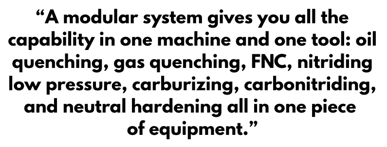
Doug Glenn: Let’s talk through the process a little bit. You provided us with figures to aid in describing the process. We have included these. Describe how the system works.
Dennis Beauchesne: This animation is a plan view of one of our Flex systems. In the center, going left to right, is a tunnel section. This tunnel section is about an 8-foot diameter. It has an automated loader that moves down left to right or horizontally, and it transfers loads from each cell to another, in and out.
On the bottom left is a loading/unloading chamber. In that loading/unloading chamber, we remove the air once the load is put in there, and then we balance the vacuum on that cell to the tunnel’s vacuum. Then we’re capable of moving that load to an available heating cell, and that would be on the right of the system — on the top right or the bottom right of the tunnel, those are heating cells. Then recipe for that particular load will be loaded into that cell. While that load is processing, another load will be moving into the tunnel and into the other heating cell as well.
On the top left is the gas quench cell, which could be in this orientation or instead have an exit on the back as well. In this system, you could do neutral hardening, carbon nitriding, LPC, a number of the processes. This is a very valuable tool, especially in a commercial heat treat heat treat shop.
Doug Glenn: Is this whole unit, including all four chambers under vacuum? I noted there are separation doors on the purge and the entry chamber. Can this area be vacuum sealed?
Dennis Beauchesne: Yes. There are vacuum seals on the loading/unloading chamber on the bottom left and then the top left. The gas quench also has a seal from a pressure standpoint. The two heating chambers have a graphite door — we call it the flap door, and it just flaps and it doesn’t really seal actually against another face of graphite. It’s graphite-to-graphite. We pull vacuum out of there through the tunnel to create the central vacuum pressure in the system. We also pull vacuum from the cell itself, and we could also have a separate door on the front of the unit if the process necessitates that or if we feel that a door is needed there by a client.
In a normal state or a standard unit, there are no hot seals on the door, only vacuum seals on the loading/unloading chamber and the gas quench.
Doug Glenn: In the animation, your vacuum pumps are down in the bottom right, correct?
Dennis Beauchesne: Exactly, that’s a process pump.
Doug Glenn: What is located in the top left?
Dennis Beauchesne: On the top left, we have a gas quench tank. We want to ensure we have enough gas pressure and volume there to quench the load quickly. It’s very important to get the gas through the gas quench quickly.
ECM Flex 600TG vacuum furnace with two added heating cells / Source: ECM USA
Now, we have added two more additional heating cells and a central tunnel section. In essence, you just doubled the space, doubled the capacity of the unit, where you only added 50% of the space of what you had for capacity before.
We are still utilizing the same gas quench and the same loading/unloading cell. We only added utilities for the two heating cells, not for a whole gas quench or oil quench capability there; this can be added in a very short time.
Doug Glenn: Now I’m gonna go let this video roll here for a minute. There we go.
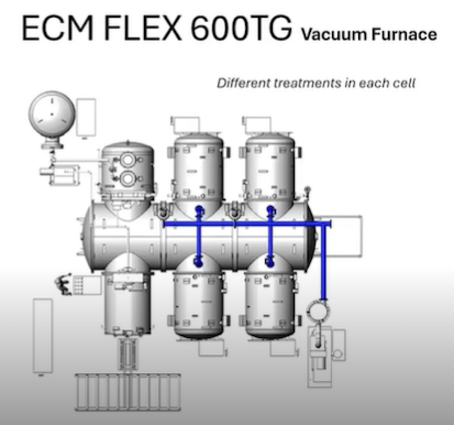
ECM Flex 600TG vacuum furnace with four added heating cells for six heating cells total
Dennis Beauchesne: So now we added another 50% capacity with two more heating cells (six heating cells total) and a tunnel section. Typically, what you want to do is to have the tunnel sized for about five years out for your capacity and then buy the cells as you need them and have it grow so then the tunnel is ready to implement.
We have just tripled the capacity of this installation, and we are only still using the same gas quench and the same loading/unloading cell. Generally, this system could go to eight cells and have just one gas quench, that’s our typical orientation.
Doug Glenn: It looks like we also added a discharge side here. Whereas before we were going in and out.
Dennis Beauchesne: Yes, this adds to the efficiency of the system because the load is already in the gas quench when it’s finishing, so it just exits out the back, out the door.
Doug Glenn: Now what do we have here?
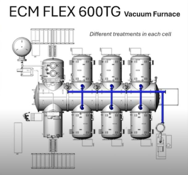
ECM Flex 600TG vacuum furnace processing different treatments in each cell. See animation above to watch the animation in motion.
Dennis Beauchesne: We have the loads entering, and the loads will go to the first cell that is available (empty). Then that recipe would be downloaded for that cell, and then the next load will go to the next available heating cell and download that recipe into that cell. These could be two different loads.
One load could be for neutral hardening; one could be for carburizing. One could be for carburizing in a low case depth. The other one could be carburizing at a deeper case. In this case, we just see the gas quench on here, but this tunnel could also be outfitted with an oil quench as well, and you could have one load go into gas, quench one load, go into oil quench or both going to either.
Doug Glenn: This gives people a sense of what the process looks like.
Processes and Materials for the Modular System (30:29)
Doug Glenn: Are there any processes or materials that do not make sense to process them through one of these systems?
Dennis Beauchesne: If you are doing a lot of annealing and normalizing, those are longer cycles. There is some regulated cooling that occurs. This is not really the type of equipment investment that you would want to make for those processes. If you were going to use it for a few loads in your plant where you received parts that weren’t annealed or you wanted to try to anneal a part for a particular process before you went to full production, you could certainly use a modular system for that, but it’s not a cost effective methodology. Neither would we recommend preheating in the cell. However, it is very flexible for a number of other processes that we have mentioned.
The size of the part is also important to note. These systems are typically 24 inches wide and about 39 inches long and about 28 inches high. However, we will soon have a new system, the Flex Max, a 12-9-9 system. It’s a 36×48 unit that comes with an oil quench and is modular, like this. We can either do an oil quench or a slow cool cell on that system. So, we will have that capability of 36×48 in that modular system.
Other than that, restrictions on material? Very few there. Like I said, you would not want to do annealing and normalizing on a lot of parts, but you could do it in these units.
Doug Glenn: It sounds like the sweet spot is surface modification type applications, and some sintering is possible with dedicated chambers.
Dennis Beauchesne: Yes, sintering and brazing is also possible.
Doug Glenn: Does that include aluminum brazing?
Dennis Beauchesne: Not aluminum brazing, but some brazing applications.
Expenses with Modular Heat Treating Systems (33:03)
Doug Glenn: What would be considered capital expenses for this modular system?
Dennis Beauchesne: As far as capital expenses, it’s not a furnace-to-furnace comparison. Clients always ask how much our furnace is. But companies need to first take two steps back and take a look at their incoming material, how they would like to be able to modify that incoming material in their heat treat process to make sure that their outgoing quality is higher than it is today. That’s the kind of benefit that this type of modular system gives you — a better quality part, safety in your plant, and a better quality work environment with being able to turn the system off and not need additional personnel around.
These are all factors that have to be considered when thinking about the CapEx expenditure and investment. When we consider these factors, a modular system investment is a much better situation than looking at a furnace-to-furnace replacement, and that’s really the thought process that clients need to go through to understand the actual investment and value of the system.
Doug Glenn: What about the operational expenses?
Dennis Beauchesne: For instances, if you had a batch IQ sitting there, you would typically keep it running whether it has a load in it or not. With a modular system, you just shut off that cell that you’re not using. It does not take any more energy. If you are not working five days a week, you do not use it on the weekends — you shut it off. You do not use it during Christmas shutdown or any holiday shutdown, vacation shutdown. You’re able to shut it off and that means saving a lot of energy and labor by having it off.
Also, in the opposite way, you could run it lights out if you wanted, as well. You could stock up a number of loads on the automation before you leave, have the system operate it, run it, and have the load come back out before the morning. You could have it time start as well, if you wanted to start it on Monday at 5 AM, but you will not be there till 8 AM. You would come in and the furnace would be hot and ready to run a process.
There are a number of operational advances over the typical operational heat treat that’s out there today.
Doug Glenn: How does maintenance work with these systems? Say your heating element goes bad in cell number three, do I have to shut the whole system down to fix or can I fix number three and leave the rest of the system up and running?
Dennis Beauchesne: In this situation if you had a tunnel like we showed, you would typically shut off that cell; that is, if you knew that heating element was out or it wasn’t heating properly, you could shut off that cell, de-validate is what we call it, and then keep running the rest of the system until you had a window in your production that you could shut the whole system to get into that heating element.
If you had a system with doors on the front, it could be possible to go in the back while the system is operating. Then, it would be all based on your safety requirements for your plant and those kinds of things.
To do that, we have another system called the Jumbo, and it is much more flexible in the maintenance world. It has a vacuum car that moves down on rails and docks and mates with every heating cell on the system. In that line, the heating cell can actually be isolated from the rest of the line. You would just slide it back (It’s on wheels, it slides back about three feet away from the line), you put in a new piece of safety fence, and you continue to run your line. You can completely lock out/tag out that cell and work on it completely.
Doug Glenn: How would you approach a vacuum leak since the whole system is connected, right? I believe you mentioned these are graphite-on-graphite doors.
Dennis Beauchesne: You would want to fix the leak before you move on. Especially if it’s a bad leak. If it’s something that’s causing you to not maintain your process pressure, you certainly don’t want to do that, and that’s true with every vacuum piece of equipment.
ECM Modular Systems (38:55)
Doug Glenn: How many of these modular type systems does ECM have out in the marketplace?
Dennis Beauchesne: The Flex is the most popular modular system, which we discussed with the animation. We also have a number of Jumbos systems, and the unit in our Synergy Center is called a Nano, which has become more and more popular these days. The Nano has three different size chambers, but they’re typically smaller, 20x24x10 inch high size chamber. I explained a little bit about the Flex and the Jumbo is the same.
Out of those three systems, we have more than 350 modular systems, not just the heating cells, but more than 350 systems that are out in the marketplace today operating, running parts every day, running millions and millions of parts every week. Those systems are comprised of about 2,000 heating cells. As much as people hear about this being a new technology, it has actually been around about 30 years, and many companies have been using these systems and have replaced a number of pusher furnaces and those style furnaces for high-capacity installations especially.
Doug Glenn: Okay, that sounds good. I really appreciate your time.
About the Guest
Dennis Beauchesne General Manager ECM USA
Dennis Beauchesne joined ECM over 25 years ago and has since amassed extensive vacuum furnace technology experience with over 200 vacuum carburizing cells installed on high pressure gas quenching and oil quenching installations. Within the last 10 years, his expertise has expanded to include robotics and advanced automation with the heat treat industry high-demand for complete furnace system solutions. As General Manager of ECM USA, Dennis oversees customer supply, operations and metallurgical support for Canada, U.S., and Mexico for ECM Technologies. He has worked in the thermal transfer equipment supply industry for over 30 years.
This Technical Tuesday installment is part of the Maintenance Message column series. In today’s edition Nate Sroka, quality assurance engineer for Ipsen, provides a complete maintenance guide to rebricking and relining atmospheric furnaces.Keep this one bookmarked for a quick reference to components, the rebricking process, expectations, and project timeline questions!
This informative piece was first released in Heat TreatToday’sAugust 2025 Automotive Heat Treating print edition.
Introduction
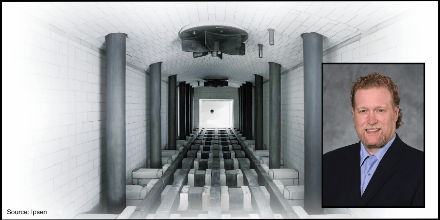
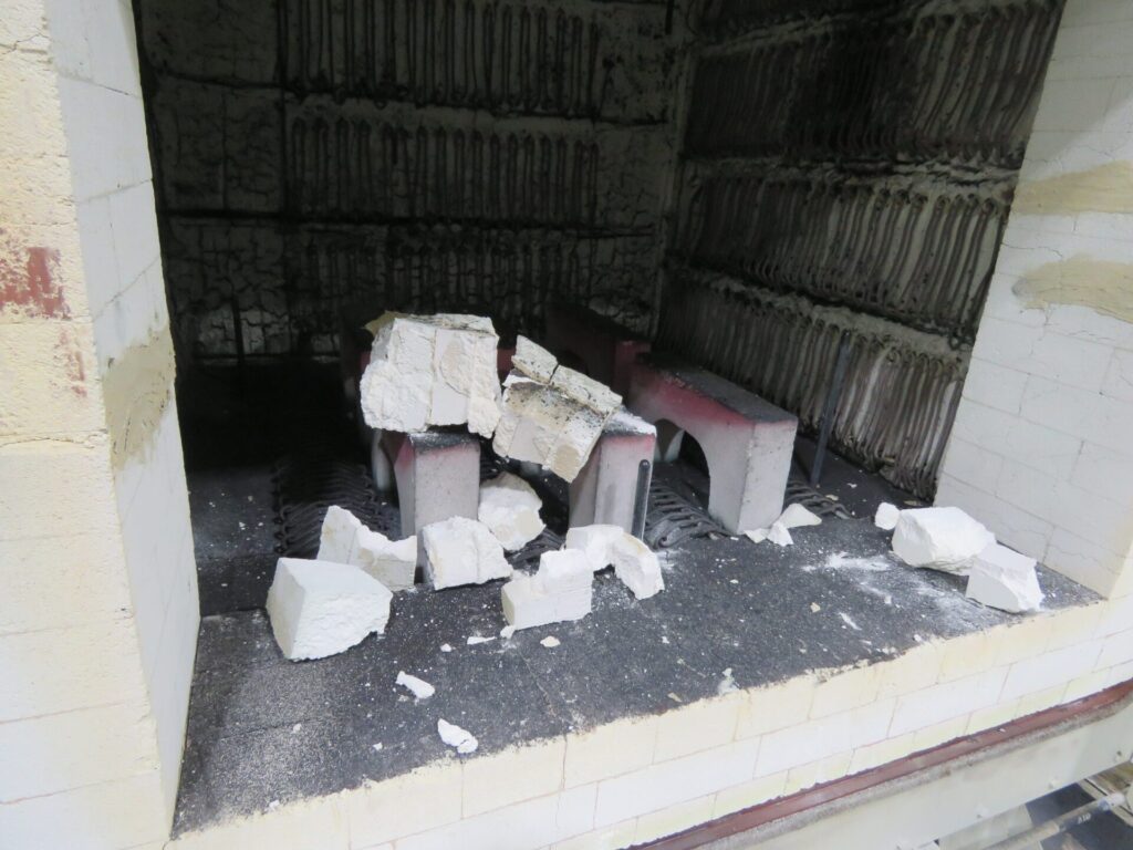
The interior brick walls of an atmosphere furnace endure extreme temperatures — sometimes reaching 2200°F — every hour of every day. Over time, the bricks become brittle, crack, and experience thermal expansion, which can open seams in the mortar.
After years of continuous operation, users may notice exterior walls becoming hot enough to melt insulated cables or components attached to the furnace. When bricks start falling out of place or insulation begins to sag, it’s time to shut down the furnace, assess damage, and plan for repairs. Typically, furnaces operating for five to ten years since installation or their last major overhaul require rebricking or relining.
Understanding the Components: Bricks and Boards
Knowing the key components used in the rebricking and relining process prepares you for discussions about repairs.
Insulated Fire Bricks (IFB) come in various temperature ratings. A 2300°F brick is less efficient and durable under extreme heat than a 2600°F brick but is often more cost-effective. High-rated bricks typically line the interior, while lower-rated bricks provide an additional insulation layer.
Insulating boards made from calcium silicate form the thermal barrier between the heating chamber and external components. They can withstand temperatures from 1000°F to 1800°F and are commonly used in lower-temperature furnaces.
Mineral wool is a fibrous insulating material used to fill gaps around furnace entry points and seams. Made from volcanic rock, ceramic, or slag, it allows for expansion and contraction due to temperature changes.
One key thing to know about atmosphere furnaces is that they are almost always “on.” In a vacuum furnace, recipes use electric elements that shut off after every cycle, and quenching often happens within the same chamber. However, in an atmosphere furnace, turning off the burners and then restarting the furnace from room temperature the next day is much less energy efficient than running the burners and holding a consistent temperature, even when the furnace is empty. Parts from an atmosphere furnace are typically quenched in an oil or salt bath, separate from the heating chamber.
Figure 1. Debris from a damaged atmosphere furnace that collapsed on a hearth Source: Ipsen
Starting the Rebricking Process: What You Need to Know
Prepare for a Quote
First, review the pre-quote checklist to make sure you have the right information to get an accurate quote.
Pre-Quote Checklist: Important information to have on hand when getting a quote for rebricking or relining your atmosphere furnace
Furnace model number and serial number
Heating chamber dimensions (w/d/h)
Archway dimensions from base to top
Door dimensions and condition
Drawings or engineering plans outlining any aftermarket modifications
Typical operating temperatures
Any additional materials installed to prevent heat penetration
Photos from as many angles of the furnace as possible
A list of any consumable or heavy-wear components that also need to be replaced
Build a Timeline
Start collecting quotes at least a year in advance and place a purchase order no less than six months before the planned shutdown.
Consider Scheduling Factors
Many furnace operators are looking to have work like this completed during a summer or winter holiday shutdown period. Advanced planning improves scheduling flexibility.
Site Preparations
Before the service team arrives, ensure the workspace is ready:
Clear space for staging new materials and removing old bricks.
Provide access to a forklift, a durable waste collection container, a dumpster, and other required tools and resources.
Confirm power connections near the site for welding and other power tools.
Review lockout/tagout procedures with maintenance and operations teams.
Determine the required furnace cool-down time before disassembly and plan furnace shutdown accordingly.
Identify and disconnect any electrical, process gas, or water-cooling lines as outlined prior to service.
Rebricking Day: What You Should Expect
During disassembly, consider performing additional maintenance, such as:
Inspecting and rotating or replacing burner tubes
Inspecting and replacing pusher chains and skid hearth section
Checking doors, door hoods, and fan bungs
Conducting leak tests and changing the quench oil
Coordinate these tasks with the service team to avoid disruptions. The rebricking process spans several days, allowing time for concurrent inspections and repairs.
Final Inspection and Testing
Upon project completion:
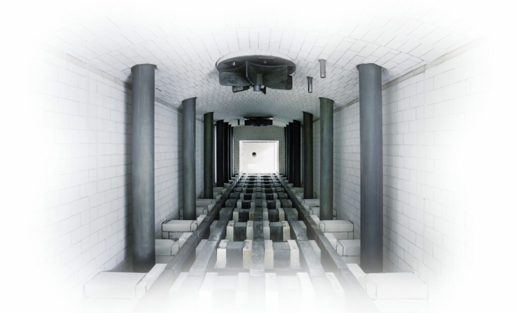
Figure 2. A newly installed furnace, bricks properly installed, before furnace ignition Source: Ipsen
Inspect the furnace with the installation team to ensure all work aligns with project specifications.
Document any changes as a reference for future maintenance.
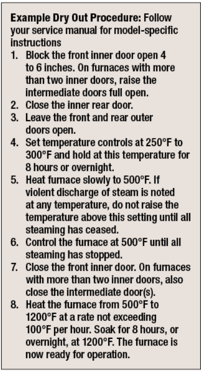
Perform a “dry out” procedure and clean the quench tank before refilling the tank. See “Example Dry Out Procedure” break-out box.
Run the furnace without parts to test for temperature uniformity.
Carburizing furnaces may need extra burn-in time to “season” the bricks:
Fresh bricks absorb free carbon until fully saturated.
When bricks are properly saturated, furnace atmospheres stabilize.
Time of burn-in is dependent on the percentage of carbon-level the system needs to achieve.
Identify potential hot or cold spots that may require further insulation adjustments.
Post-Installation Best Practices
A rebrick or reline of a furnace is a significant investment. To get the most from your furnace, make the time to take a proactive approach:
Establish a daily maintenance inspection for the first week, followed by weekly checks for the first month.
Resume regular maintenance schedules if no issues arise.
Schedule independent inspections with a field service engineer at three, five, seven, and nine years to proactively assess furnace condition and secure preferred maintenance dates.
By following these steps, atmosphere furnace operators can maximize uptime, streamline service quoting, optimize downtime usage, and ensure efficient future rebuilds.
This article was originally published on ipsenusa.com.
About The Author:
Nate Sroka Quality Assurance Engineer Ipsen
Nate Sroka has been with Ipsen since March 2014. He holds a bachelor’s degree in mechanical engineering and a master’s degree in engineering and industrial management from Northern Illinois University. Nate oversees the Quality/Documentation/Warranty (QDW) department, ensuring that Ipsen maintains ISO 9001 and ISO/IEC 17025 standards. He is also responsible for documentation related to installation and operations manuals, regulatory certificates, and managing warranty programs.
For more information: Contact Nate Sroka at nate.sroka@ipsenusa.com.
If you are one of many heat treat professionals watching AM take over the industrial world with bated breath, it may be time to stop watching and start doing. This article highlights the rapid rise of AM and how changes in your heat treat operations may be needed.
This informative piece was first released inHeat Treat Today’sAugust 2025 Automotive Heat Treating print edition.
For manufacturers who produce customized or complex parts and components for the medical, aerospace, automotive, and other industries, additive manufacturing (AM) with metals has the potential to bring innovation and agility to the process.
However, because AM is a somewhat nascent technology, there are still challenges to address before it is widely accepted throughout the manufacturing industry. Fortunately, as research and development continue, the aerospace and automotive industries are beginning to acknowledge that parts made via AM are robust enough for use in safety-critical applications. Manufacturers who want to use AM to gain a competitive edge are advised to zero-in on the most suitable method for metals and determine in which applications AM presents an economically viable solution.
The Additive Manufacturing Market
AM, also known as 3D printing, is the process of creating an object based on a digital file, such as a computer-aided design (CAD) or one created with a laser scanner. Unlike traditional manufacturing methods that often involve cutting or subtracting material from a solid block (like machining), AM involves building up thin layers of material — usually metal, ceramic, or plastic — one by one using a 3D printer.
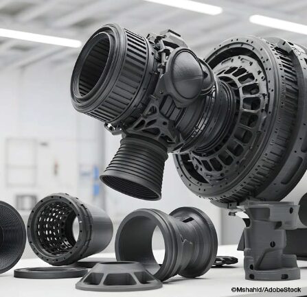
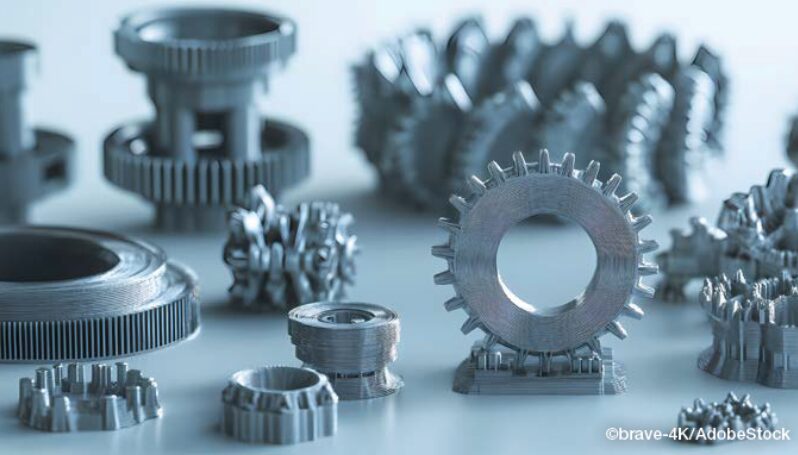
AI-generated image of 3D-printed turbine engine components
AM is increasingly transforming the manufacturing industry, enabling faster prototyping, customized production, lightweight parts, and complex shapes and geometries that would be impossible to manufacture using conventional casting, machining, or subtractive techniques, such as milling, grinding, carving or shaping.
For product design, prototyping, and reverse engineering applications, AM allows designers to rapidly print parts as a single piece, reducing material waste, saving time, and reducing costs, all while getting new products to market faster. Although the same advantages apply to traditional manufacturing applications, manufacturers have not been as quick to adopt the technology.
Still, the AM industry is seeing growth. A recent report from Grand View Research states that the global AM market size was valued at over $20 billion in 2023 and is expected to grow at a CAGR of 23.3% from 2023 to 2030, with unit shipments of 3D printers expected to reach 21.5 million units by 2030 thanks to a growing demand for prototyping applications in the healthcare, automotive, aerospace, and defense industries. The report also acknowledges that rigorous R&D in 3D printing will further contribute to growth.
Additive Manufacturing Techniques for Metals
Currently, three primary techniques are used for AM with metals: laser powder bed fusion (LPBF), directed energy deposition (DED), and binder jetting.
LPBF
LPBF technologies, including direct metal laser sintering, selective laser sintering, and direct metal printing, use a laser to sinter or fuse powdered metal particles until a complete part if formed. LPBF processes typically include heating the bed of powdered metal to a consistent temperature. The printer begins applying the first layer over a build plate, fuses the powder particles together with a high-powered laser, and then continues the process layer-by-layer until the part is finished.
After the part is printed using LPBF, it is removed from the powder bed, cut away from the build plate, heat treated to prevent internal stresses, and finally machined or polished to achieve the desired surface finish.
LPBF is limited by the size of the print bed, so it is not suitable for manufacturing large components or parts.
DED
DED using powdered metals also relies on a laser to produce metal parts. However, rather than spreading powder on a bed, the DED machine blows powdered metal out of the print head and uses a laser to fuse the part during construction.
DED-manufactured parts require post-processing heat treatment and machining steps. And while DED is a faster process than LPBF, there are a limited number of materials that can be used in the DED process, and the technique still needs more research and development before it sees widespread commercial use.
Binder Jetting
Binder jetting deposits a layer of loose metal followed by a layer of binder material layer by layer to create the product. During the process, a binder jetting machine distributes metal powder over the print bed to form an unbound layer. A jetting head then spreads a binder to adhere the powder. The machine continues to spread alternate layers of building material and binder to form a complete product. Sintering is generally required after printing to remove the binder, resulting in a part that is composed entirely of metal.
While binder jetting is a fast process and offers the opportunity to create and sinter parts in batches, it is currently a more expensive option. However, research and development into this technology, the availability of binder jets from companies (e.g., Markforged and HP), and the potential to use binder jetting for high-volume batch production may eventually make binder jetting the technology of choice for metal AM.
Post-Processing Heat Treatment for AM Parts
No matter the print technique, some AM-printed metal parts will require post-process heat treatment in which the printed part is subjected to specific temperatures and durations and then cooled to enhance or customize the properties of the metal material and optimize performance and reliability of the part.
Applying controlled heating and cooling cycles during post-printing heat treatment eliminates internal stresses created during the AM process to prevent distortion, cracking, and warping that would negatively impact part performance and reliability. Heat treating can also be used to increase hardness, density, strength, and fatigue resistance to optimize performance of the part. Furthermore, heat treating can be applied to customize the mechanical properties of the final part and provide specific characteristics so that it performs reliably in the intended application.
The type of heat treatment used following AM will depend upon the printing technique, metal material, and desired characteristics and properties. Annealing, sintering, normalizing, quenching, and tempering are commonly used. Hot isostatic pressing (HIP) — another post-process option that is used to reduce porosity and improve the density, performance, and reliability of AM-printed parts — will be specifically addressed in a subsequent article release.
Greater Acceptance in Industry Sectors
Metal alloy 3-D printed components
While AM has been widely used for prototyping and reverse engineering, adoption of the technology has been slower for the manufacture of finished parts and components. Stephen Feldbauer, director of Research and Development, with Abbott Furnace Co., suggests that the right approach to AM with metals depends upon the ability of manufacturers to refine their application. “Manufacturers should not take the ‘shotgun’ approach of ‘I can print anything,’” comments Feldbauer. “Instead, they should focus on what makes the most sense for them and specialize in those parts rather than just printing something because it’s possible.
However, because it provides significant benefits, AM does have application in the several manufacturing sectors. Advantages in using AM to produce parts include minimization of waste, time and cost efficiency, and the ability to customize parts for single-use applications or low-volume production runs.
Thanks to these benefits, AM is currently being used in the following industries:
Aerospace: functional parts, such as engine turbine blades and fuel systems
Automotive: various components, such as suspension systems, engine parts, and door panels
Defense: obsolete parts, as well as vehicle and weapon components
Medical: implants, prosthetics, and other apparatuses
And, as AM technology continues to expand, it is becoming more widely accepted and is most notably being employed to create safety-critical aerospace and automobile parts. For example, General Motors (GM) announced that it is using AM-printed seatbelt pillar adjustable guide loops in its all-electric Cadillac Celestiq, making them GM’s first safety-related AM-printed metal part.
The component is made by Azoth using Markforged metal binder jetting technology with a liquid binding agent. Following the process, the metal parts are then sintered, polished, and plated. Automotive sector acceptance of additive manufactured safety-critical parts is a tremendous boon for the AM industry.
Experts like Feldbauer see the need for manufacturers to make a few key decisions for this technology to become a reality. “For additive manufacturing to be a commercially viable solution,” he argues, “manufacturers must determine which parts they can 3D print with high levels of success and where printing is cost effective and profitable. Commercial viability is really the determining factor as to whether a part should be 3D printed or made using conventional manufacturing techniques.”
Currently, though, AM seems to be benefiting smaller jobs. According to Feldbauer, AM usually makes the most sense for small runs where there is a need for customized tooling; in these cases, manufacturers run into too complex of shapes or simply to time or cost intensive.
The Future of AM
While AM is increasingly accepted as a beneficial process across many industries, it still faces challenges affecting its usage more broadly, such as material restrictions, bed or plate sizes for techniques that rely on bed printing, and the need to purchase high-end printers from a market that is constantly consolidating. Research and development into the process, more diversity in technologies, increased availability of AM outsourcing companies, and the benefits associated with cost, time, and material reductions are expected to be a driving force in widespread commercial adoption.
Stephen Feldbauer, director of Research and Development with Abbott Furnace Co., updated Heat Treat Today on the state of AM in 2025
As the technology continues to mature, AM will continue to expand into industries where the availability of high-volume AM production, such as is possible with binder jetting, would reduce the cost of part manufacturing. Additionally, optimizing post-process heat treatment methods will help further enhance the cost effectiveness of AM with metals and enable more customized characteristics. These advances could make AM an attractive and economical option for manufacturers, so those who want a competitive edge should begin to focus and refine application of AM to the parts for which it will be most worthwhile.
References
Grand View Research. 2022. Additive Manufacturing Market Size, Share & Trends Analysis Report by Component, by Printer Type, by Technology, by Software, by Application, by Vertical, by Material, by Region, and Segment Forecasts, 2024 – 2030. April 2022. Grandview Research. Report ID: GVR-4-68039-922-9. https://www.grandviewresearch.com/industry-analysis/additive-manufacturing-market#
Check out our AM/3D Trivia to test your knowledge of the AM/3D industry, the processes, and the technology.
This editorial was written by the Heat Treat TodayEditorial Team.
In this Technical Tuesday installment featuring Combustion Corner by Jim Roberts, president of U.S. Ignition, readers are enlightened about how upcoming policies might impact their burner systems, fuel mixtures, and equipment. Could certain policies impact technical requirements of heat treating? Find out more below.
This informative piece was first released inHeat Treat Today’sJuly 2025 Super Brands print edition.
A furnace guy goes into a bar and says, “This looks like a fast crowd… and all the players nod in agreement.”
Where are we? It’s the future! And in heat treating and combustion circles, the changes that will occur in the next several years will be very impactful to our industry. We’ve all heard these things, and we have some of the very best experts in the world working for us in this industry to make sure that we continue to grow and to be a leader in the legislation and rules that could cripple the wonderful world of heat treating and metals.
We are lucky to have industry associates at the Metal Treating Institute (MTI)who understand the impact of some of these new regulations. In this year’s Air & Atmosphere issue of Heat Treat Today magazine, Michael Mouilleseaux (Erie Steel LTD) provided updates on the proposed decarbonization initiatives. I have seen presentations by Michael and his committee composed of Heather Falcone (Cook Induction Heating Company) and Ben Gasbarre (Gasbarre Thermal Processing Systems). This is critical knowledge for us all, and we should be staying as vigilant and supportive as we can. Michael’s interview is a must-read in that February issue – if you missed it, go back and read it. Please.
And then you say, “What’s this got to do with combustion equipment and the stuff that this Roberts guy is normally talking about?”
Well, not only does the decarbonization mandate mean the possibility of costs through government burdens and penalties, but the equipment and process change requirements are going to be staggering if we don’t prepare.
As long as I’m in a name-dropping mood, I’m going to mention Brian Kelly of Honeywell. Brian is a degreed aerospace engineer, and yet he decided to come play in the mud with us furnace guys for a career. Brian has several detailed presentations online about some of the prime initiatives for all the combustion equipment companies — hydrogen Combustion. Yep, the “H” word. The holy grail of zero pollution. One of those presentations includes fascinating detailed data on hydrogen and other emission initiatives, given by Brian Kelly and Todd Ellerton on YouTube regarding future combustion technology requirements.
“So, what does the “three times faster” thing mean, Jim?”
Well, all major combustion equipment companies, like Honeywell, understand that hydrogen requires three times the amount of fuel to generate the same amount of available heat as natural gas. Hydrogen also burns with seven to eight times the “flame speed” of natural gas. It burns, on average, about 400 degrees hotter (F) than natural gas. And so, from an engineering standpoint, there are a fantastic number of variations that must be considered as we look forward, especially when addressing CO₂ and other emissions. Add propane, butane, methane, producer gas, landfill gas, and anything else that is presently being utilized in the heat treat circles, and that provides a lot of possible variations!
Now, it needs to be said that a good many burners can burn hydrogen already. The anticipation of this level of scientific and ecological requirements was seen a long time ago. Conversely, many cannot. Brian Kelly explains that 17% of the present pre-mix/blended fuel systems cannot utilize this fuel. It also bears mentioning that there are three different grades of hydrogen production levels.
So, let’s start doing the math on how many iterations it will take. But here is the biggest tidbit of hydrogen science in the combustion world – hydrogen is the smallest molecule and the lightest in a molecular sense. Helium is smaller and lighter, for fact-checker purposes, but we aren’t trying to burn helium, are we? So, as we blend hydrogen with our other fuels (i.e., the most practical way to maintain some of the infrastructure and equipment), we need to have our combination equipment suppliers test and verify that which exists will work.
Obviously, if it takes three times the fuel volume, existing gas delivery lines will be an issue. At the molecular level, smaller and lighter means that many existing seals, connections, and control valves may no longer be gas-tight and may leak. That’s not good! If the flame speed of these fuels is five to eight times that of existing fuels, temperature profiles within the process will need to be reviewed and re-calibrated. And if it burns 400 to 500 degrees hotter, certainly that will require a review of the former materials of construction.
So, how does this tie into the original theme of “The future is coming fast?” Well, we have just touched briefly on one possible fuel transition that is on the horizon. Carbon points/credits are already being taxed in Europe. We can bet that these global decarbonization efforts will be moving ahead. We will need a review so that a “head in the sand” mentality does not catch any of us in the thermal processing community flatfooted and ill-prepared.
It’s easy to think that it won’t affect you. When I mentioned “three times as fast,” of course, I was alluding to the fuel references, and the best way to be prepared for the future is to see it coming. Be alert and stay current, and we will adapt as an industry, as we have so many times before. Until next time …
About The Author:
Jim Roberts President US Ignition
Jim Roberts president at U.S. Ignition, began his 45-year career in the burner and heat recovery industry focused on heat treating specifically in 1979. He worked for and helped start up WB Combustion in Hales Corners, Wisconsin. In 1985 he joined Eclipse Engineering in Rockford, IL, specializing in heat treating-related combustion equipment/burners. Inducted into the American Gas Association’s Hall of Flame for service in training gas company field managers, Jim is a former president of MTI and has contributed to countless seminars on fuel reduction and combustion-related practices.
For more information: Contact Jim Roberts at jim@usignition.com.
Heat treatment impacts almost every facet of our lives, yet few people are aware of how important this practice is to a modern way of living. Heat treatment is a process which changes the microstructure of a metal, such as hardening, carburizing, tempering, and many others.
When a metal is formed, it undergoes heat treatment in order to make it longer lasting, change its structure so that it becomes harder or softer, or reduce the tendancy toward cracking which can form during manufacturing. To help us appreciate the impact of heat treatment on our daily lives, Tiffany Ward, daily editor for Heat Treat Today, has prepared this illustrative post.
Breakfast of Champions
You wake up in the morning and roll yourself out of bed, greeting a foggy sunrise through the window. You stumble to the kitchen to fire up your cast iron skillet.
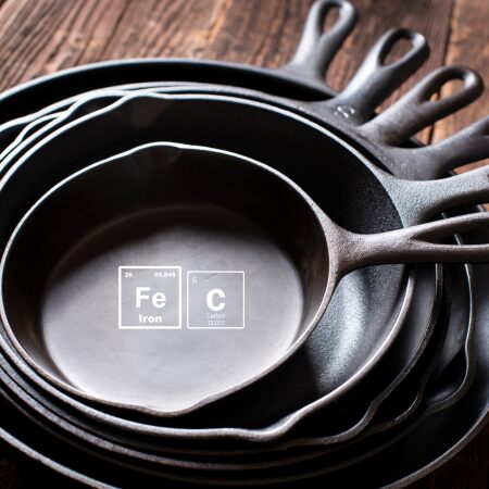
Cast iron contains a minimum of 2% carbon
At one time, that same cast iron skillet lived a provincial life, known as simply: iron. Cast iron is made from iron with greater than 2% carbon, which is in the form of graphite. When that iron was “cast,” it was melted at a high temperature, and once cooled, it transformed into a very stable material that heats and cools uniformly. Perfect for your sunny-side-up eggs.
At the foundry, someone poured the molten metal into a mold to form the exact shape your pan is in today, and then it underwent numerous heat treat processes: annealing, normalizing, tempering, and even graphitizing (a process of converting carbon into graphite). The particular processes the skillet underwent depend upon the chemistry of the cast iron.
Almost all cast iron has carbon and nitrogen added to its surface in a process called ferritic nitrocarburizing plus post-oxidation. This heat treatment gives a shallow surface layer to the pan for better wear resistance. The skillet is heated up between around 1550°F and 1650°F inside a protective atmosphere of Endothermic gas. Endothermic gas is a generated heat treat atmosphere. It is made up of approximately 40% hydrogen, 40% nitrogen, and 20% carbon monoxide. The Endothermic gas is enriched with both a hydrocarbon gas (i.e., natural gas or propane) and ammonia so that carbon and nitrogen can be added to the iron.
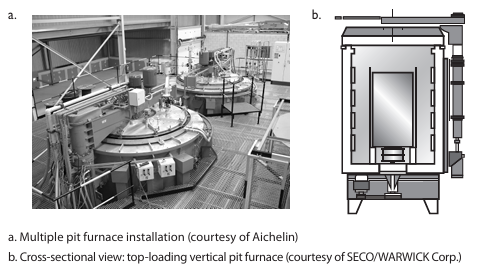
There are a variety of different furnaces that can be used for ferritic nitrocarburizing. Box, pit, and tip-up furnaces are used due to their large capacity. For cast iron skillets, one common choice is the pit furnace — a cylindrical furnace typically located in the floor of a factory. Pit furnaces can hold a lot of heavyweight items, making them a good fit for the cookware now resting on your stove.
Figure Source: Herring, Daniel H., Atmosphere Heat Treatment Volume 1, BNP Media II, LLC, 2014.
You pull a knife out of your drawer and begin slicing an apple. The blade reflects a beam of sun from the window, but it isn’t your best knife. You’ve noticed that some of your knives are sharper and can resharpen more easily than others; this is because of the quality of the original material used and the heat treatment process employed in manufacturing the knife.
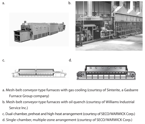
Perhaps the knife you chose to use today was made from high carbon steel such as 1095. The blade was heat treated using a process of hardening, quenching, and tempering. After the blade was formed, it entered a continuous mesh-belt furnace and was quenched in either oil (in the case of a 1095 steel), or in the case of stainless steel or tool steel, cooled in still air.
Source: Dan Herring, The HERRING GROUP, Inc.Figure: Batch integral-quench furnace system installation (courtesy of AFC-Holcroft). Dan Herring, The HERRING GROUP, Inc.
At the same time of hardening and quenching, the handle was joined to the blade in a process called brazing. The entire knife was heated up to an austenitizing temperature and rapidly cooled in the quenching process, giving it a particular hardness level.
The hardening process can be performed in a vacuum furnace or an atmosphere furnace. The atmosphere is typically nitrogen or, more commonly, a nitrogen/hydrogen mixture. Another option is nitrogen plus dissociated ammonia (dissociated ammonia is 75% hydrogen, 25% nitrogen).
A typical temperature for the heat treatment of high carbon 1095 steel knives is 1475ºF. Stainless steels are run at higher temperatures, typically in the range of 1800º/1950ºF and tool steels even higher, to around 2200ºF.
After breakfast you head to the bathroom. You are anxious to rid yourself of unshaven scruff, carefully running a razor over your face. The razor blades were hardened and tempered for sharpness, so that you get a smooth, clean shave.
Like knives, razor blades are hardened and are made of a medium to high carbon steel. Unlike knives, they are hardened in a continuous strip form. Envision all of your razor blades as a single, thin strip, run continuously through a furnace to heat and cool them. The blade is heated in a protective atmosphere as it runs through the furnace. On one end of the furnace is a reel that coils the strip and at the other end is an un-coiler.
Continuous style furnaces have alloy tubes inside of them that are very small in diameter, typically one inch, which run the entire length of the furnace. As the razor strip is run through the tube it is exposed to an atmosphere of nitrogen and hydrogen, typically with 3% hydrogen, to protect the razor blade surface from oxidation. Once heated, the blade enters cooling either by surrounding the tube with water or by blowing forced air on the tubes.
A process called tempering follows hardening and quenching. When you harden a material you make it stronger, but less ductile, so there is a concern that the razor blade might break. The tempering process improves ductility, removing some of the hardness but improving flexibility.
Dan Herring, The Heat Treat Doctor®, describes the balancing act this way: “On one end of the teeter totter, metallurgically, are strength properties and on the other side of the teeter-totter are ductility properties. It’s always a challenge to properly balance the teeter-totter. If you get the hardness too high, what happens to the ductility? It’s very low. As a result, the material is super hard but may crack easier. On the other hand, if ductility is too high, the material is super flexible so that it can bend like a branch of a tree in the wind, but it has little strength. You need a balance of strength and ductility in all heat treated products, which is accomplished in part by proper tempering.”
Our lives are touched by heat treatment at every turn. Highly technical processes play their role in the formation of even the most common household items. While heat treatment may seem to some a niche industry, its impact on everyday life is ubiquitous.
A special note of thanks to Dan Herring, The Heat Treat Doctor®, for his insights and contributions which informed this post.
In today’s Technical Tuesday installment, we highlight the various techniques and developments in the world of metal AM as it pertains to post-process heat treating. Check out the trivia quiz below to test your knowledge of the AM/3D industry, the processes, and the technology.
This feature was first released inHeat Treat Today’sJanuary 2025 Technologies To Watch in Heat Treating print edition.
Additive manufacturing (AM), commonly known as 3D printing, has a history marked by constant innovation for uses across the space, aerospace, medical, food, and manufacturing industries, to name a few. While AM is known to support, streamline, and customize part production, advanced materials paired with evolving AM techniques are creating new possibilities in materials engineering and industrial manufacturing. Due to the nature of this ever-developing technology, in-house heat treaters must continually learn about AM components and how thermal processing may enhance component properties.
Emanuel “Ely” Sachs
What was the original name for additive manufacturing (AM), circa 1980s? A) 3D printing B) Rapid prototyping (RP) C) Additive manufacturing (AM) D) Rapid tooling (RT)
What grade of stainless steel is most commonly used for AM to achieve varying levels of strength, hardness, and elongation when heat treated? A) 17-4 PH B) 316L C) 304 D) 430
Who is Emanuel “Ely” M. Sachs? A) An engineer at GE Aviation who combined multiple parts into one huge, complex design using a laser-based additive manufacturing method called direct metal laser melting B) An engineer at Stratasys Ltd., an American-Israeli manufacturer that began using a material extrusion based process with their FFF (fused filament fabrication) technology to print parts, patented in 1989 C) A professor of Mechanical and Materials Engineering at Worchester Polytechnic Institute who evaluated the post process heat treating of DMLS titanium alloy parts D) An MIT engineering professor who patented the process of metal binder jetting technique in 1993
What do cast parts made from powder metallurgy methods and AM parts have in common? A) The same heat treatment cycles produce the best results B) Custom cycles are used in less than 2% of both applications C) Parts exhibit porosity D) None of the above
What are the most commonly adjusted parameters to achieve higher yield strength when heat treating AM parts? A) Cooling and heating rate B) Temperature and time C) Time and pressure D) Temperature and pressure
Why is HIP known as the “gold standard” for processing AM parts for space? A) Eliminates porous microstructures without compromising the part’s geometries and dimensions B) High level of control and uniformity C) Combines high temperature and pressure to improve a part’s mechanical properties D) All of the above
What is NOT a potential benefit of additive manufacturing? A) Immediate cost savings B) Fast part production C) Rapid prototyping D) Opportunity for increased automation and use of robotics
What are the two main categories for most 3D printing methods? A) Those that use liquid binding polymers, and those that don’t B) Binder jetting technology (a non-melt-based process) and melt-based processes C) Both A and B D) Neither A nor B
Which alloy was originally developed for aerospace applications but became one of the most common biomedical alloys? A) Inconel 718 B) Inconel 625 C) Ti-6Al-4V D) Hastelloy C22
What was the first rapid prototyping method to produce metal parts in a single process (and is one of the most widely used AM technologies to manufacture Ti-6Al-4V parts)? A) Powder-bed fusion (PBF) B) Directed energy deposition (DED) C) Sheet lamination (SL) D) Direct metal laser sintering (DMLS)
In what way does high temperature processing — specifically HIP below the annealing temperature (1470°F/799°C) — improve DMLS Ti-6Al-4V parts? A) Preserves surface roughness and enhances osteointegration B) Reduces porosity and enhances corrosion resistance C) Both A and B D) Neither A nor B
What is the ideal way to process 3D printed parts made using liquid binder polymers? A) Print the parts in-house followed by debind and sinter. B) Have AM parts delivered in-house for heat treating when parts are at the “Green” stage C) Have AM parts delivered in-house for heat treating when parts are at the “Brown” stage D) None of the above
Industry experts agree: 2025 is a year of significant, high-tech developments. In this Technical Tuesday, hear from three heat treat industry consultants on current and incoming technological advances, from miniaturization and customization to artificial intelligence.
Michael Mouilleseaux, general manager at Erie Steel, Ltd, opens the discussion by asking what role AI has in a perfect world of heat treating; Thomas Wingens, president of Wingens Consultants, predicts six major technologies to look for in 2025; and Dan Herring, a.k.a. The Heat Treat Doctor® and owner of The HERRING GROUP, Inc., points out how the trend toward smaller is affecting the heat treat industry.
This informative piece was first released inHeat Treat Today’sJanuary 2025 Technologies To Watch in Heat Treating print edition.
AI’s Place in Heat Treating?
by Michael Mouilleseaux
The benefits of AI are purported to be the ability to reduce the time required to complete complex tasks, such as data analysis, while reducing human error and providing both unbiased decision making and data-driven system enhancements … and by the way, it can operate 24/7 without breaks!
Does AI have a place in heat treating?
Here’s what I would want my heat treat AI (HT AI) to be able to do with a gas-fired atmosphere furnace.
Combustion System:
My HT AI will continuously monitor the free oxygen of all the burners and keep them at a perfect ratio, thereby optimizing performance and gas consumption. It will track these changes and provide analysis of any trends that it “perceives,” so to speak.
My HT AI will continuously monitor combustion air pressure and message me in time to have the air filters changed before it affects performance. It will track this and provide historical and prescriptive information.
My HT AI will periodically perform a “tube check,” whereby it will shut off combustion in a tube and monitor the free oxygen, recognizing that any diminishment from “atmospheric” O2 levels indicate the potential of a tube leak. It will track this and provide analysis of any trends that it perceives.
My HT AI will track when system thermal stasis is achieved, monitor gas consumption for each discrete heat treat cycle, provide analysis of trends that it perceives, and recommend thermal cycle changes to optimize these cycles.
My HT AI will facilitate the optimization of the critical human assets in process engineering, product quality and equipment maintenance.”
Michael Mouilleseaux
Atmosphere Control System:
My HT AI will continuously monitor the atmosphere flows required to achieve the requirements for each heat treat cycle. It will track “atmosphere recovery” and provide analysis of any trends that it perceives (i.e., increased usage as a precursor to a furnace leak).
My HT AI will periodically perform a furnace check, whereby it compares the composition of the Endo gas in the furnace to that exiting the generator, providing a measure of furnace integrity. It will track this and provide analysis of any trends that it perceives.
My HT AI will confirm “tube check” data (see above) with atmosphere usage to evaluate its potential effects on process integrity and make actionable recommendations. It will track these incidents and provide analysis of any trends that it perceives.
My HT AI will provide assurance of system performance and actionable information.
Shoot for the Moon:
My HT AI will have the unique ability to integrate metallurgical results with process information and thereby provide the ability to optimize the heat treating process AND metallurgical results.
My HT AI will allow me to input material chemical and hardenability data and, by comparing actual results with the calculated, or prospective results, provide confirmation of the thermal and quenching segments of the process.
My HT AI will be able to correlate IGO results with furnace integrity checks (i.e., leaks) and over time establish hard limits for allowable leak rates.
My HT AI will be able to correlate actual retained austenite levels in carburized case with furnace carbon potential and make data-driven process modifications to optimize this.
My HT AI will be able to correlate the shape of the case depth curve with the carburizing cycle and the material type, and it will make data-driven process modifications to optimize this.
My HT AI will have the ability to develop new heat treat thermal cycles specific to my furnaces extrapolated from existing data.
My HT AI will provide a level of system performance heretofore not achieved, that not only assures adherence to established standards but provides a clear path of continuous improvement via data analysis and actionable actions. Product results will be validated by total process control, and total process control will assure attainment of product results.
My HT AI will facilitate the optimization of the critical human assets in process engineering, product quality and equipment maintenance.
In short, my HT AI will afford the heat treating community the ability to finally jettison the mantle of “black art” and join the community of high-tech engineered processes.
About the Author:
Michael Mouilleseaux General Manager Erie Steel, Ltd
Michael Mouilleseaux has been at Erie Steel in Toledo, OH, since 2006 with previous metallurgical experience at New Process Gear in Syracuse, NY, and as the director of Technology in Marketing at FPM Heat Treating LLC in Elk Grove, IL. Having graduated from the University of Michigan with a degree in Metallurgical Engineering, Michael has proved his expertise in the field of heat treat, co-presenting at the 2019 Heat Treat show and currently serving on the Board of Trustees at the Metal Treating Institute.
2025 will be the year of invention and application. There are six major technologies to be looking out for: AI management software, giga casting for the EV industry, high-pressure quench furnaces, thermal processing specialty materials, processing for steel enrichment, and practices for cleaning consistency.
AI Management Software
Some new heat treat shop management software is now available. It utilizes artificial intelligence to save labor while documenting all processes in real time. The software easily adapts to the way we work and is much easier to learn and implement than the software of the past. I see this as the number one investment item for commercial heat treaters in 2025, as it is the cheapest and easiest way to automate with a great ROI while increasing quality and customer service.
Giga Casting
With Tesla as the main driver, very large so-called “GIGA” H13 aluminum dies of 3 to 8-ton weight have really taken off in the last years, in particular for new electric car models, and the demand for very high pressure quench furnaces is increasing in the U.S. (more to come in a later article).
Vacuum Oil Quenching
However, even with the most advanced designs and high-pressure efforts, gas quenching with nitrogen has its limits, and the use of helium is not considered anymore because of its immense cost, even with a recycling system in place. Vacuum oil quenching has become a viable alternative in recent years not only in combination with LPC (low-pressure carburizing) but also with the use of materials like AISI 52100 that would be typically heat treated in atmosphere integral quench furnaces but show lesser distortion with the variation of pressures over the oil bath, which can shift the oil boiling phase peak to lower temperatures (e.g., from 650°C (1200°F) at atmospheric pressure to 400°C (750°F) at 1 mbar pressure). Some new modern vacuum oil quench furnace designs have recently entered the market, showing excellent surface cleanliness and distortion results. Aside from the better quality, they offer a much safer, cleaner and more pleasant work environment.
Specialty Materials
In general, we see a higher demand for the thermal processing of specialty materials; for example this is seen with the hydrogen decrepitation of titanium, tantalum, niobium, or rare earth element materials, powder processing or sinter processes, and surface diffusion processes.
Steel Enrichment
Enriching stainless steel with nitrogen is not new, but it is gaining momentum and more applications. One method for\ low-temperature processes on austenitic stainless steels around 370°C (690°F) is called S-phase case hardening, and the high temperature version around 1100°C (2010°F) is called solution nitriding. Both processes were initially established in the early 90s in Europe but seem to be gaining momentum and more comprehensive applications worldwide over the last years.
Figure 1. For 2025, “We see more fully enclosed vacuum solvent cleaning in heat treat shops to ensure a higher standard and consistency of the surface cleaning results compared to the fading of water cleaners.” – Thomas Wingens, WINGENS CONSULTANTS
Cleaning Consistency
Speaking of surface processes: The cleaning of components has been a thankless process, especially in commercial heat treatment, as it is seen as a necessity that is not necessarily paid for by the clients but is necessary to have uniform dissociation on the surface of a part to ensure a uniform case (e.g., nitriding case). There are well-defined standards for temperature uniformity and hardness testing, but cleaning consistency needs to be addressed, as it can be very impactful. We see more fully enclosed vacuum solvent cleaning in heat treat shops to ensure a higher standard and consistency of the surface cleaning results compared to the fading of water cleaners.
About the Author:
Thomas Wingens President WINGENS CONSULTANTS
Thomas Wingens has been an independent consultant to the heat treat industry for nearly 15 years and has been involved in the heat treat industry for over 35 years. Throughout his career, he has held various positions, including business developer, management, and executive roles for companies in Europe and the United States, including Bodycote, Ipsen, SECO/WARWICK, Tenova, and IHI-Group.
Everywhere we turn today, the products we use are getting smaller, more compact and more powerful. This is true across all industries, from aerospace to automotive, from medical to electronics, and from energy to semiconductors to name a few. Today, miniaturization, portability and customization have become major design objectives for almost all manufacturing segments.
These trends are irreversible and are, or will be, found even in the most unlikely of places — both in mining of resources taking place deep under the ocean floor and eventually on other planets. The key question then becomes, how will all of this influence our heat treating operations?
Miniaturization, Portability and Customization Today
Given the ever-increasing demand for higher performance in a smaller footprint, we have often focused our energies on taking existing products and adapting them for use. But in the long term, this is not sustainable. For example, not only is gear noise reduction critical in our submarines, but the medical and robotics markets are continuously searching for smaller, more efficient, more application specific and more intelligent drive systems and motors with increased torque density.
Heat treatment will experience a metamorphosis and emerge more broadly as thermal treatment. The age of metals as we have known it has become the age of materials: ceramics, composites, powder materials, glasses, polymers, fiber-reinforced plastics, and even nanomaterials.
Dan Herring, The Heat Treat Doctor®
Another example, although not new, is miniaturization in vehicle electronics, especially as it relates to data collection where demand is high for smaller, more powerful and, yes, cheaper components. Integration into the electronic control units via on-board power systems has seen the need for more cables in vehicles and positioning connectors, which means more contacts/connections on the electronic components without significantly increasing the installation space.
Similarly, there is a huge demand for portability. This is true not only in our electronics (just think about how cell phones or computers have changed over the last ten years), but there is a growing need for portable medical devices so that medical care can be brought to the patient rather than the other way around. For example, longer battery life and lighter weight are critical for devices such as portable oxygen concentrators.
What Does This Mean for the Heat Treatment Industry?
Looking ahead, we will see both short and long-term changes to our industry. Happening today and continuing in the near term, heat treaters are working closer than ever with design and manufacturing engineers as they focus on products that reduce environmental impact, are produced at lower unit cost, and with improved part quality. Still, the era of mass recalls must come to an end. And the cost of heat treating is less than it was even a decade ago. But as manufacturing demand evolves due to consumer expectation, process and equipment flexibility will become keys to meeting the highest quality standards in an on-demand world.
Historically, changes in the heat treat industry has been evolutionary and incremental in both nature and effect. There have been notable exceptions such as the invention of the oxygen probe or low pressure vacuum carburizing. But to meet the manufacturing demands of the future, change will need to be more revolutionary and abrupt in nature, a game changer.
Given the ever-increasing demand for higher performance in a smaller footprint, we have often focused our energies on taking existing products and adapting them for use. But in the long term, this is not sustainable. For example, not only is gear noise reduction critical in our submarines, but the medical and robotics markets are continuously searching for smaller, more efficient, more application specific and more-intelligent drive systems and motors with increased torque density.
Dan Herring, The HERRING GROUP, Inc.
Heat treatment will experience a metamorphosis and emerge more broadly as thermal treatment. The age of metals as we have known it has become the age of materials: ceramics, composites, powder materials, glasses, polymers, fiber-reinforced plastics, and even nanomaterials. As a result, we will find ourselves needing, for example, to expand our heat treat capability and equipment to deal with such items as process temperature ranges from -200°C to 1850°C (-330°F to 3360°F) or greater or at pressure/vacuum levels heretofore only achievable in laboratories or specialty applications.
As product sizes decrease, load sizes will become smaller out of necessity. And as a result, our heat treat equipment must be small lot capable with tighter controls to achieve higher quality along with tremendous process flexibility.
Final Thoughts
History’s enduring legacy is that change is inevitable. Just think back to how the heat treatment industry has evolved, from the campfire to the blacksmith to the modern heat treater, from the artisan to the era of mass production, from the art of heat treating to the science of heat treatment. The lesson is that to adapt, one must constantly innovate and invent. Miniaturization, portability and customization in whatever form they take are here to stay. Perhaps even teleportation (the ultimate miniaturization?) isn’t that far off after all, considering flight was unheard of a little over a century ago.
About the Author:
Dan Herring (The Heat Treat Doctor®) The HERRING GROUP, Inc.
Dan Herring has been in the industry for over 50 years and has gained vast experience in fields that include materials science, engineering, metallurgy, new product research, and many other areas. He is the author of six books and over 700 technical articles.
The Heat Treat Doctor® has returned to offer sage advice to Heat Treat Today readers and to answer your questions about heat treating, brazing, sintering, and other types of thermal treatments as well as questions on metallurgy, equipment, and process-related issues.
Contact us with your Reader Feedback!
Clients often want to know or specify that their component part surfaces are “bright” or “shiny” or “clean.” Other times they desire to have a surface condition that is “scale free” or “oxide free” after heat treatment. But how, if at all, can we quantify what these terms mean? Let’s learn more.
“Shiny” and “bright” are words that are highly subjective. This is often a source of confusion not only for the heat treater, but the manufacturer and, in some cases, even the end user of the products. Heretofore, the answer depended on one human being’s interpretation as opposed to another, and evaluations depend not only on the type of material but also the mill practices used, manufacturing methods employed, heat treatment processes, and the level and type of contamination introduced before and after processing.
Traditional Approach
Figure 1. Temper color chart atmosphere or tempering in air or an “inert” gas such as nitrogen. Source: Abbott Furnace Company
Traditionally, we have relied on color charts (Figure 1) to tell the approximate temperature at which discoloration took place, that is, an oxide formed on the (steel, stainless steel, or tool steel) surface of a component part. This method is still in use today when cooling parts in a furnace
As mentioned, the perception and interpretation of color is different for different people. Lighting (natural light or plant illumination), the environment in which one views color, eye fatigue, the age of the observer, and a host of other factors influences color perception. But even without such physical considerations, each of us interprets color based on personal perception. Each person also verbally describes an object’s color differently. As a result, objectively communicating a particular color to another person without using some type of standard is difficult.
There also must be a way to compare one color to the next with accuracy.
New Approach
Today, portable spectrophotometers (Figure 2) are available to measure color and help quantify brightness measurements. These types of devices are designed to meet various industry standards including:
In simplest terms, a spectrophotometer is a color measurement device used to capture and evaluate color. Every object has its own reflectance, or the amount of light it reflects, and transmittance, or the amount of light it absorbs. A reflectance spectrophotometer shines a beam of light and measures the amount of light reflected from different wavelengths of the visible spectrum, while a transmission spectrophotometer measures how much light passes through the sample. Spectrophotometers can measure and provide quantitative analysis for just about anything, including solids, liquids, plastics, paper, metal, fabric, and even painted samples to verify color and consistency.
Spectrophotometers provide the solution to the subjective problem of interpreting the color of the surface of a component part that has been heat treated, brazed, or sintered because they explicitly identify the colors being measured; that is, the instrument differentiates one color from another and assigns each a numeric value.
As an example, the brightness of steel tubes annealed in a rich Exothermic gas atmosphere was measured against tubes that had not been processed (Figure 3). Having this definite measurement of the surface changes allowed the heat treater to provide their client with a definitive statement on the change after processing.
CIE Color Systems
The Commission Internationale de l’Eclairage (CIE) is an organization responsible for international recommendations for photometry and colorimetry. The CIE standardized color order systems include specifying the light source (illumination), the observer, and the methodology used to derive values for describing color, regardless of industry or use case.
Though spectrophotometers are the most common, for some applications colorimeters can also be used, but these are in general less accurate and less suitable for a heat treat environment.
There are three primary types of spectrophotometers on the market today used for print, packaging, and industrial applications: traditional 0°/45° (or 45°/0°) spectrophotometers, primarily used for the print industry; sphere (or diffuse/8°) spectrophotometers, primarily used in the packaging industry; and multi-angle (MA) spectrophotometers, for use in industrial environments. These instruments capture color information, and in some cases can capture appearance data (e.g., gloss).
Multi-angle (MA) spectrophotometers are best suited for measurements involving special surface effects, such as those found on metal surfaces and coatings and include those with surface contaminants and even can quantify cosmetic appearance. These are typically used on the shop floor, in the lab and in quality control, and even can be found in shipping areas.
MA spectrophotometers require users to verify five or more sets of L*a*b values or delta these terms). They typically have an aperture size of 12 mm, which is too large for measuring the fine detail that occurs in many small-scale industrial applications. Primary illumination is provided at a 45° angle. Some models have secondary illumination at a 15° angle.
Figure 3. Example of a product test — color and oxidation level test. Source: X-RIte
An application example for an MA spec trophotometer lies in their use for collecting colorimetric data on special effects coatings in the automotive industry, capturing reliable color data in cases where special effect coatings are used.
Final Thoughts
In this writer’s opinion, a spectrophotometer should be in every heat treat shop! You will be doing both yourself and your customers a valuable service and take the guesswork out of one of the most commonly asked questions – is it bright?
References
Herring, Dan H. Atmosphere Heat Treatment Volume 1. BNP Media, 2014.
X-Rite Pantone. “A Guide to Understanding Color.” Accessed October 10, 2024. https://www.xrite.com/learning-color-education/whitepapers/a-guide-to-understanding-color.
X-Rite Panatone. “Tolerancing Part 3: Color Space vs. Color Tolerance.” Accessed October 10, 2024. https://www.xrite.com/blog/tolerancingpart-3.
X-Rite Pantone. “X-Rite Portable Multi Angle Spectrophotometers.” Accessed October 10, 2024. https://www.xrite.com/categories/portable-pectrophotometers/ma-family.
About the Author
Dan Herring “The Heat Treat Doctor” The HERRING GROUP, Inc.
Dan Herring has been in the industry for over 50 years and has gained vast experience in fields that include materials science, engineering, metallurgy, new product research, and many other areas. He is the author of six books and over 700 technical articles.