3 Top Tips for Brinell and Rockwell Hardness Tests
Accurate hardness testing is a critical business for numerous industries, not least heat treatment. In this guide, we will offer our “best practice” list for getting the best possible reading for your hardness test with the most efficiency.
This Technical Tuesday article was written by Alex Austin, the managing director at Foundrax Engineering Products Ltd.
1. Tip for All Tests


Managing Director
Foundrax Engineering Products Ltd.
Source: Foundrax
Make sure the test equipment is properly set up. In most instances, this involves keeping the test machine serviced and calibrated in accordance with the international standards (ASTM E-10 for Brinell and ASTM E-18 for Rockwell) or the manufacturer’s instructions — whichever are more strict — along with mounting it on a level, vibration-free surface. The absence of vibration is crucial if you are using a lever and weight machine, but still desirable for hydraulic and motor-driven types, and it is mandated by the standards.
It is worth noting that for tests made using portable Brinell hardness testers that apply the full test load (albeit without the ability to maintain it uninterrupted for the full ten seconds), while it might not always be possible to mount the machine on a solid and level surface, the rest of the above still applies.
If the anvil is mounted on a leadscrew, ensure that it is properly secured. Similarly, jigs should be in good condition, correctly mounted and hold the test piece securely. It is easy to become very relaxed about the amount of energy that goes into applying 3000 kg to a 10 mm ball, but if the component shatters under load the results can be dramatic and, potentially, very dangerous.
Don’t forget your safety boots! Also, as fingerprint residue is corrosive, always wear gloves.
2. Brinell Hardness Testing
Preparation
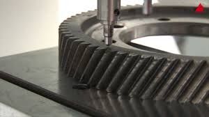
Before performing a Brinell hardness test, make sure both the test area and the indenter ball are clean and free of all lubricants. Oil or grease on the test surface or indenter could wreck the test by lubricating the path of the indenter, making a very significant difference to the apparent hardness level. For example, at 300 HBW the material may appear around 20 HBW softer than it actually is. Moreover, it can change the appearance of the indentation edge, causing a false diameter measurement. In any case, the hardness standards are clear that test pieces must be clean and lubricant-free.
Prepare the area of the component surface where the test is to be carried out so that the indenter comes into direct contact with the core material. For this, the skin must be removed, including any decarburized layer, using a hand grinder with 60 grit abrasive (or finer, if appropriate) in 3–5 seconds, if a good automatic Brinell microscope will measure the indentation, or 10–15 seconds for a good manual microscope. This time differential is on the basis that a good automatic system will measure hundreds of diameters and ignore grinding “noise” when identifying the true edge of the indentation. On the other hand, use of a manual microscope is limited to the number one can reasonably measure by the time available and the equipment at hand. However, in the case of both automatic and manual testing, the better the surface, the better the result.
Next, place the material on the test machine’s table or anvil. Ensure that it is stable and cannot move under the test load (machines with an integral clamp are preferable from this point of view). The clamp should be holding the material so that the test surface is perpendicular to the indenter’s line of operation.
Carrying Out the Brinell Hardness Test
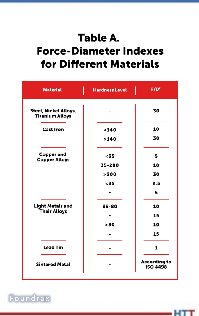
Use the correct force-diameter index (F/D²) for the material being tested; see Table A.
Apply the test force in accordance with ISO6506 or ASTM E-10, as appropriate. While the indenter is in downward motion and in contact with the material, avoid doing anything that might create vibrations that could reach the machine. When the indenter has withdrawn, measure the resulting indentation in a minimum of two diameters perpendicular to each other and convert the mean measurement into an HBW number.
If using a portable Brinell hardness tester, exercise caution when removing the machine from the component so that the edge of the indentation is not accidentally damaged when the machine is released.
3. Rockwell Hardness Testing
Preparation
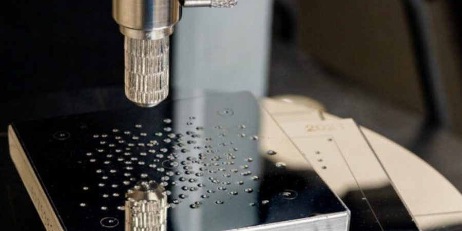
Cleanliness is everything in Rockwell testing. The indenters are much smaller than those used in Brinell testing and (as you would expect) so are the indentations (see Figure 1). And because the Rockwell test measures indentation depth, not width, any contaminant or particle that gets between the indenter and the material is a problem. Underside contamination is almost as important. There have been instances of clients finding that the testing block seemed to render two hardness points lower than we stated, yet in every instance, we found a buildup of soft contaminants (e.g., grease, oxides, micro-swarf) on the underside of the block. These contaminants “give” as the indenter is driven into the block, thereby permitting further indenter travel than would occur in the block material alone.
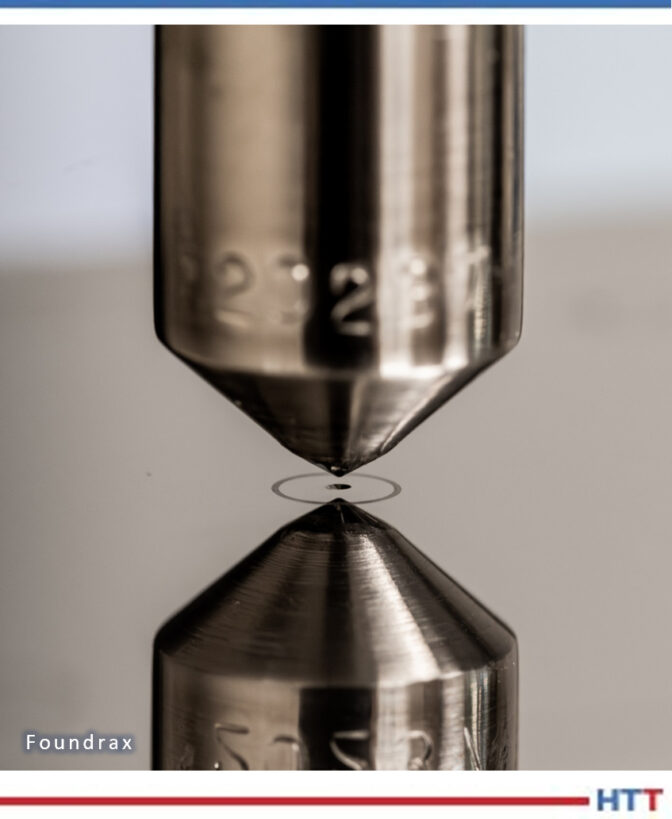
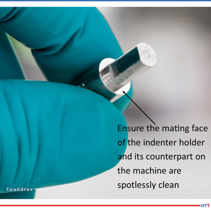
Lubricant contamination on the block surface is obviously extremely problematic. All blocks should be cleaned with a cloth and a liquid solvent that leaves minimal residue (e.g. isopropyl alcohol). Tissue paper can be used for cleaning but can scratch aluminum and brass easily; untreated cotton wipes are preferable. The anvil should also be cleaned by gentle application of a lint-free cloth dampened with solvent, and the indenter itself should be gently wiped at intervals throughout the test session. Another place where contaminants can build up (easily producing an error in excess of one Rockwell point) is the mating face where the indenter holder is inserted into the test head of the machine (see Figure 2).
It is obviously also essential that the anvil mount cannot budge under the indenting load. If it is mounted on a vertical threaded column, the column should be free of excess grease and tightened to the point of no movement. Column “give” is another area where we have detected consequential erroneous readings.
A further notable check worth performing is that the block, or test piece, has not been dropped and landed on a corner of the underside, which would leave a burr. This would prevent the piece from sitting flush on the anvil and probably negate the possibility of correct readings, as the piece would move under the indenter load.
Procedure
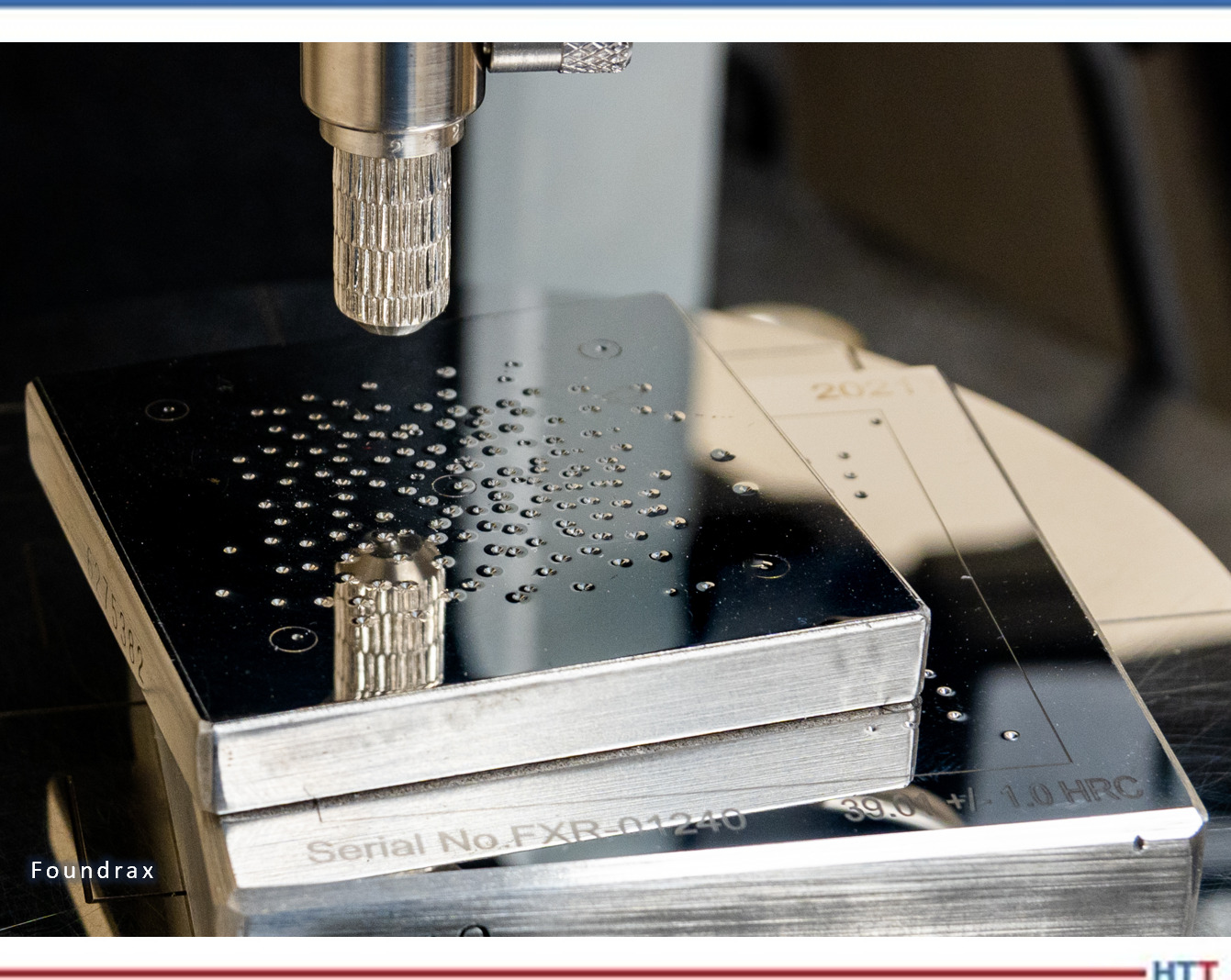
If the first indentation on a block suggests a lower hardness than the remainder, there is a chance that air was trapped underneath it. The first indentations usually drives any air out, but in the case that air remained trapped beneath the indenter, the hardness reading will be falsely soft; the block will have moved downwards as it displaced the air, and the indenter will, therefore, have travelled further than if the block were truly sitting flush on the anvil. Placing a block that is softer than the test material on top of the test block and putting one indentation into it before commencing the tests will eliminate this problem (see Figure 3).
Have an aerosol duster to hand during indenting to keep the block surface clear.
Test blocks should, ideally, be stored in airtight cases to reduce the rate at which oxides form on their surfaces. Better still, wrap them in rust-reducing paper as well.
(Photo Source: Foundrax Engineering Products Ltd.)
About the Author: Alex Austin has been the managing director of Foundrax Engineering Products Ltd. since 2002. Foundrax has supplied Brinell hardness testing equipment for 60+ years and is the only company in the world to truly specialize in this field. Alex sits on the ISE/101/05 Indentation Hardness Testing Committee at the British Standards Institution. He has been part of the British delegation to the International Standards Organization advising on the development of the standard ISO 6506 “Metallic materials – Brinell hardness test” and is the chairman and convener for the current ISO revision of the standard.
For more information:
Contact www.foundrax.co.uk
Find heat treating products and services when you search on Heat Treat Buyers Guide.com
3 Top Tips for Brinell and Rockwell Hardness Tests Read More »