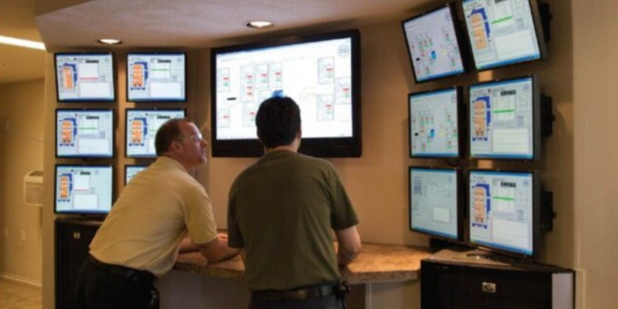
A software system was installed at Allied Locke in Dixon, Illinois, to assist heat treat processing by providing continuous data logging and access to both real time and historical data. The system provides communication with 6 batch IQ furnaces.
This SuperDATA system, from Super Systems Inc., is the first phase of a multi-phase project, with future expansions planned for tempers, endothermic generators, and CAN-ENG mesh belt furnace lines. SuperDATA contains a communication and data logging module, a visualization module and a trending module. The system will aid Allied Locke, who produces for these sectors: agricultural chain, precision roller chain, industrial chain, sprockets, and environmental products.
Find heat treating products and services when you search on Heat Treat Buyers Guide.com
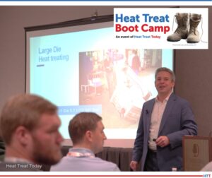
Heat Treat Boot Camp, an event ofHeat Treat Todayprovides basic training to those new to or inquisitive about the North American heat treat industry. From a technical perspective, the event provides an explanation of thermal processes and materials so that non-technical people can understand.
This Technical Tuesday original content piece provides a list of some of the content that will be covered in the sessions being offered this September 18-20 in Pittsburgh, Pennsylvania.
Introduction
Technical session with Doug Glenn Publisher and Founder Heat Treat Today Source: Heat Treat Today
The event kicks off with a welcome reception on Monday evening, September 18, at the Doubletree by Hilton Hotel & Suites in downtown Pittsburgh. Coincidently, this is the same evening that the Pittsburgh Steelers have a home game against the Cleveland Browns. The hotel should be busy with activity since it is located quite near the stadium.
Day 1: Technical Presentation on Heat Treat Basics
On Tuesday, September 19th, the technical portion of the event kicks off with a presentation on Heat, Markets, and End Products. This presentation addresses what is heat treating and why you should care. It delves into the reasons why we heat treat and covers properties like strength, toughness/softness, durability, flexibility, corrosion resistance, heat resistance, wear & friction resistance, as well as biocompatibility.
Technical session with Thomas Wingens Owner, Founder, President WINGENS LLC Source: Heat Treat Today
The session also covers the three sources of heat typically found in industrial processes, how heat is measured, and how it is transferred. A discussion about some of the major markets in which heat treating is used. Products being heated and the processes being used are briefly covered.
Day 1: Technical Presentation on Processes and Materials
The next session on Tuesday, September 19, goes a bit more technical to cover some of the processes performed and materials treated. Processes like annealing, tempering, stress relieving, hardening (both surface and through), homogenizing, normalizing, nitriding, and carburizing to name a few are covered in such a way that it is understandable for non-technical attendees.
Day 1: In-depth Presentation on Equipment Used in Heat Treating
Following lunch on this first day, the group takes a whirlwind tour of the different types of heat treating equipment, components, and supplies used in the heat treat industry along with a brief discussion of the high-heat materials needed to construct the equipment. Some of the specific topics covered include air & atmosphere furnace systems, vacuum furnace systems, induction heating equipment, heat sources including burner, heating elements, and induction power supplies, heat treating control systems including instrumentation, recorders, and controllers, as well as alloys and fabrications, ceramics, refractories, and insulations, quench media, as well as materials characterization & testing equipment. There is a huge amount of basic information covered in this session, preparing the attendee to understand enough about each system to recognize where each fits into the heat processing universe.
Day 1: Field Trip to Local Highlight
Atop Mt. Washington after riding the Duquesne Incline Source: Heat Treat Today
The final session on the first day digs deeper into processes and materials and covers things like the types of steels, aluminum, and other nonferrous metals and how they are thermally processed.
In the evening on the first day, the group takes a trip to the famous Duquesne Incline, which is an historic Pittsburgh icon, and the evening ends with a group dinner.
Day 2: Industry Movers and Shakers
The second day is only a half-day in classes followed by an off-site plant tour — this year of Penna Flame in Zelienople, Pennsylvania, one of western Pennsylvania’s leading commercial heat treaters and one of the nation’s leading flame hardening job shops. The day starts, however, with a discussion of heat treat “players” — suppliers to the heat treat industry, including furnace and induction heating equipment manufactures, burner and heating element suppliers, on-site and industrial gas suppliers, control system and instrumentation manufacturers, insulation providers including both metal, graphite, and ceramic insulations, alloy and fabrication companies, as well as cooling systems and quench suppliers, and materials characterization & testing equipment manufacturing companies.
Day 2: The Latest in Heat Treating and Off-Site Plant Tour
Networking and learning from each other Source: Heat Treat Today
The last two sessions before lunch and the plant tour include a discussion of some of the newest developments and innovations including 3D printing and hot isostatic pressing, as well as AI and sensor and instrumentation advances and a brisk discussion of other industry resources such as associations, institutes, and societies, media outlets, trades shows, training programs, etc.
The standard Boot Camp ends after lunch on the second day, September 20th, unless you’ve signed up for the plant tour of Penna Flame which is located less than one hour north of Pittsburgh in scenic Zelienople, Pennsylvania. Owners Jim, Michael, and Andrew of will greet the participants and give them an informative tour of their third-generation commercial heat treating shop which specializes in flame hardening. The company has also invested significantly in robotic heat treatment equipment and is well worth the trip. Participants should be back to the host hotel no later than 6:00 on Wednesday, September 20th. The heat treat shop tour costs an extra $95 dollars.
Learn More/Register
In 2022, over 30 attendees participated with positive reviews from nearly all. For more information on the 2023 event and to register, visit www.heattreatbootcamp.com. Early Bird registration ends on July 31st, and final registration closes on September 15.
Find heat treating products and services when you search on Heat Treat Buyers Guide.com
Generally, electric power consumption is insidious, because it is not seen and is not considered enough by operating personnel. Uncover sources of power consumption at a typical heat treat plant and ways to conserve it.
This column is written by William Jones, CEO and founder/owner of Solar Atmospheres Group of Companies, and Roger A. Jones, CEO Emeritus at Solar Atmospheres, Souderton, PA, and appeared in Heat TreatToday’s June 2023 Heat Treat Buyers Guide print edition.
If you have suggestions for topics you’d like to see in the future, please email Bethany@heattreattoday.com.
William Jones CEO and Founder/Owner, Solar Atmospheres
Generally, electric power consumption is insidious, because it is not seen and is not considered enough by operating personnel. The following is a summary of power consumed in a typical heat treat plant along with several ways to conserve power (and money) in operating costs.
Electric Motors
Roger Jones
CEO Emeritus, Solar Atmospheres, Souderton, PA
Electric motors are prolific throughout a heat treat plant. Some areas where they would be found include:
Water recirculation pumps for cooling purposes
Vacuum pumps
Circulation pumps for oil used in quench tanks
Fans
Quench motors
High Vacuum Diffusion Pumps
High vacuum diffusion pumps operate with no noise, which adds to the insidious nature of their power consumption; operating costs for these pumps are more or less “out of sight.” To ensure diffusion pumps are not increasing costs, confirm that all diffusion pumps are set to run on the ConserVac® settings with full power (all three phases on) during high vacuum cycle and partial pressure cycles running on half power (one or two phases off). When possible, turn off/ shut down the diffusion pump.
Variable speeds of gas blowers can decrease power consumption, especially at the end of a cooling cycle when the heat of compression is noticeable. To do this, program all quench cycles to shut down the blower at the lower temperature as required on the work thermocouples (i.e., 125°F) and do not run blowers for excess time.
Building/Office Lighting, AC, and Heating
There’s more to saving than just focusing on vacuum equipment. Consider the following list of ways to reduce everyday power consumption:
Turn off all office and shop lights when not needed, except for night lights. Make sure all office lights are off during non-working hours and weekends.
Use newer, high efficiency type building lights.
Program office heating and air conditioning for setback, like office lighting.
Lesson to be learned: turn off any electric motor or light whenever it is not in operation.
Costs of Running Electric Motors @ 10 cents/KWh
Furnace Heating Rate
No furnace should be heated any faster than 15°F to 30°F/minute or 900°F to 1800°F/hour, unless specific instructions mandate otherwise.
Scheduling and Power Demand
Understanding the utility company, peak times for electricity usage, and scheduling appropriately can decrease energy consumption and cost. The following are a few suggestions to direct thinking around scheduling and power demand:
Utility company provides an electric power meter for kWh and demand kVA
Meter contains a power demand register
Record of electric power usage over a specific time increment
Instantaneous demand peak recorded each month
Result is the total kW hours registered in one part of the bill and the second part of the bill is kW electrical power demand
Ideal situation: instantaneous power demand would be flat with no demand peaks for the month, but this is not the norm
Batch type electric furnaces can produce major demand peaks:
Major electric power savings are possible if equipment can be controlled so the peak demands can be staged, i.e., over several furnaces
Schedule heavy production cycles to “off peak hours” usually during the evening, i.e., after 6 pm to 8 pm
Some utility companies will not penalize for the demand factor during “off peak hours”
Electric furnaces that operate with “on/off” control using electric contactors are offenders
The furnace will call for full power in the “on mode”
When temperature reaches the set point, power will be completely turned off
Electric power can easily be peaked if several batch furnaces operate in this mode together
Solution: replace the electric on/off contactors with SCR (silicon controlled rectifier) power supplies
SCR controllers will provide a proportional power control, minimizing peaked power demand
Operating Costs for Diffusion Pumps, Varian Diffusion Pumps
Power Factor Conclusions
It is important to be aware that:
Power factor can significantly affect the electric power bill if the electric utility charges a penalty for operating at power factor less than unity or bills in kVA rather than kW.
Electric furnaces that operate with resistance heating elements connected directly across the power line, or incandescent lighting in the plant operate at near unity power factor.
Utility companies penalize users in different ways for power factor and penalties vary by location.
Motors will have an average power factor of 0.8%.
Furnace power supplies will have variable power factor depending on loading, averaging about 0.65.
In Summary
There are many ways to conserve dollars in any ongoing manufacturing or heat treating plant. Knowing what — and how — power is consumed in heat treat departments helps operators identify areas to conserve energy in vacuum processing and also in day-to-day operations. Other than “turning off the lights,” many other opportunities are available to operating personnel as outlined above.
We’re addressing problems our readers operating older equipment face: Does your safety logic measure up?
This column is a Combustion Corner feature written by John Clarke, technical director at Helios Electric Corporation, and appeared in Heat Treat Today’sJune 2023 Heat Treat Buyers Guide print edition.
If you have suggestions for topics you’d like John to explore in the future, please email Bethany@heattreattoday.com.
John B. Clarke Technical Director Helios Electric Corporation Source: Helios Electric Corporation
This month we will break temporarily from our discussion of radiant tubes systems to address a problem faced by our readers who operate older equipment. Does your safety logic measure up? Have you availed yourself of the latest thoughts about how to best construct a safe system?
The National Fire Protection Association (NFPA) publishes various codes and standards to guide the design of heat process equipment. These codes and standards are under constant review by experts in the field and are updated regularly. The latest versions of NFPA 85, 86, 87, and others are readily available for download at nfpa.org/Codes-and-Standards for about a hundred dollars. The investment in reviewing new versions of critical standards provides valuable insight into the thinking of experienced professionals who apply their ongoing experience as they seek to make our combustion equipment ever safer.
The standards above are generally prescriptive — in that they specify devices and locations, but they also teach the reason behind specific requirements if the reader slows down and thinks logically. An example of this is the requirement in NFPA 86 that states the motor starter which drives the combustion air blower (or other critical devices) be included in the interlock string. If the blower motor pulls too much current, the motor starter’s overload relays trip, shutting off the combustion air blower. A fuel rich condition is prevented because as soon as the blower trips, the interlock string is interrupted and the shutoff valves close, preventing any further fuel gas from being introduced to the system. The code also specifies that a low combustion air pressure switch (or draft switch) be applied; but these devices take time to react to the failure, and with safety logic, the sooner a system is rendered safe, the better.
Monitoring the motor starter and the combustion air pressure switch are on the prescriptive side of the standard, but let us think a bit more about this requirement. Loss of the combustion blower is a critical failure. Are there other failures that can shut off the blower that would not be indicated by the auxiliary contact on the motor starter? If the motor fuses were to blow, or a line of sight disconnect were to be opened, would the interlock detect this failure? What can I do to detect these conditions? Perhaps it would be appropriate to monitor not only the contact on the starter, but the current pulled by the motor using some type of current relay?
The safeties that were installed on my system were good enough when it was manufactured in 1990, why upgrade them now? That is a fair question, but one of those questions that is best answered with another question. Has technology advanced in the last 30 years? Have we gained experience, learned from our mistakes and successes? The answer is yes.
So why not avail yourself of the experience learned by the professionals that volunteer their time to ensure our codes and standards encompass their collective experience? Your assignment is to purchase and download the latest version of the applicable codes or standards and take the time to review them. The reading is pretty dry, but the payoff can be extremely beneficial.
Find heat treating products and services when you search on Heat Treat Buyers Guide.com
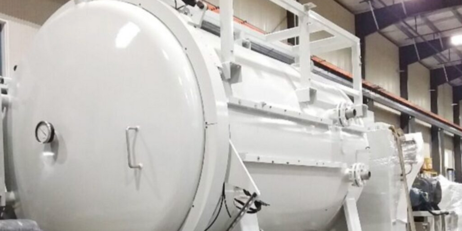
A vacuum furnace recently shipped to a U.S.-based aerospace fastener manufacturer. The furnace will be primarily used to age-harden various fasteners of high strength alloys used in the aerospace industry.
This is the second Model HFL-5748-2IQ furnace for this manufacturer. Like the first furnace, the new furnace features a graphite insulated hot zone of 36” x 36” x 48” deep with a weight capacity of 5,000 lbs., a maximum operating temperature of 2400°F, and a 100 HP quench motor. The control system was customized to interface with the customer’s in-house automation system for recipe control and data acquisition.
“Our customer needed additional furnace capacity to keep up with demand,” commented Jason Davidson, regional sales manager, Solar Manufacturing.
Find heat treating products and services when you search on Heat Treat Buyers Guide.com
Discover expert tips, tricks, and resources for sustainable heat treating methods Heat TreatToday’srecent series. And, if you’re looking for tips on combustion, controls systems, or induction in general, you’ll find that too! Part 2, today’s tips, digs into energy and electricity. We’ve added another resource towards the end of today’s post to further enrich your knowledge of induction heating.
This Technical Tuesday article is compiled from tips in Heat TreatToday’sMay Focus on Sustainable Heat Treat Technologiesprint edition. If you have any tips of your own about induction and sustainability, our editors would be interested in sharing them online at www.heattreattoday.com. Email Bethany Leone at bethany@heattreattoday.com with your own ideas!
1. Maximizing Energy Efficiency of Vacuum Furnaces
Contact us with your Reader Feedback!
The use of AC to DC transformers is an energy-efficient innovation that can significantly lower energy consumption of the heating system. Typically, a system uses alternating current as the primary source, which fluctuates output during each half cycle. Using AC to DC transformers limits these fluctuations, reducing the amount of energy used. Furthermore, transformers operate at optimal efficiency when under a reduced load – i.e., less than 70% output in steady-state heating – rather than ramping up to the full operating temperature. Another advantage of the DC-type transformer is that its operating power factor is very close to 1.0, which lowers the utility company’s calculation of peak demand surcharges
Try power feedback for your electric heating elements. Power feedback is ideal for variable resistance heating elements. Kilowatts are used as the unit of control, rather than just current or voltage.
Conserving energy is not only good for the environment, but it can mean more money in your pocket and less downtime. Here are three tips to improve furnace efficiency with diagnostic technology:
Do you have tight and secure terminal connections? Poorly connected power cables waste electricity and can cause fires. An SCR power controller monitors terminal temperature changes and will alert you before failures happen. It also monitors heat sink temperatures and ensures the control’s cooling fan is working properly.
Do you have a heater-break alarm? Heating zones typically have multiple heating elements, wired in parallel. A broken element is difficult to detect and will impact the heater’s circuit, reducing the power of the process. This can waste energy and affect product quality. A heater-break alarm will alert you to a failing heater circuit.
Do you pay high electricity bills? You could benefit from a factory load management system. It’s now possible to limit peak current loads and power usage across your factory and multiple furnaces. These systems communicate by sharing important power-demand information and providing more effective power distribution.
A connected and automated factory network saves electricity and improves operational efficiency by establishing powerful furnace management systems.
After absorbing today’s tips, you may want to take one step farther to read up on induction heating. Take a look at “Why Induction Heating is a Green Technology” to help broaden the horizon.
Find heat treating products and services when you search on Heat Treat Buyers Guide.com
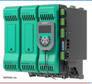
Advanced Heat Treat Corp. (AHT) announced the addition of a new gas nitriding system at its corporate headquarters located in Waterloo, Iowa. The system increases their Iowa location’s size capabilities for gas nitriding and gas nitrocarburizing. The equipment can also be used for stress relieving.
The new gas nitride system can accommodate parts up to 26′ high and has a trademarked heat treat process for wear and corrosion, UltraOx®. The equipment will serve applications within the industries of plastics, oil and gas, hydraulics and more.
“Now we are able to better accommodate large and long parts at all of our nitriding locations,” commented Mikel Woods, president at AHT.
Find heat treating products and services when you search on Heat Treat Buyers Guide.com
Heat Treat Today is partnering with two international publications: heat processing, a Vulkan-Verlag GmbH publication that serves mostly the European and Asian heat treat markets, and Furnaces International, a Quartz Business Media publication that primarily serves the English-speaking globe. Through these partnerships, we are sharing the latest news, tech tips, and cutting-edge articles that will serve our audience — manufacturers with in-house heat treat.
Take a look at new tech and equipment, an old furnace, positive profits and reports, and lasting partnerships.
International Heat Treat and Metallurgy Company Sees Doubling Profits
SECO/WARWICK’s positive figures for 2022
Source: SECO/WARWICK
“The great results of the Group were influenced by several factors. The growth of production activities in China and dynamic market development in America. Furthermore, the huge number of orders [are] related to the electromobility industry expansion. In the first three quarters of 2022, the company had over 100% more profit than in the previous year. Sales revenues amounted to PLN 448.87 million in this period (PLN 335.09 million in 2021). . . For SECO/WARWICK, 2023 will be the year of American companies.”
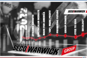
System aids in the production of various steel grades
Source: Tenova
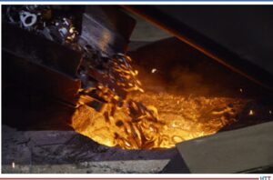
“Tenova, supplier of sustainable solutions for the metals industry, has recently completed the start-up of the new 70t EAF at the Valbruna ASW Inc. plant, located in Ontario, Canada. Valbruna ASW is a specialty steel producer that produces steel and stainless-steel, based in Ontario. Tenova’s latest generation EAF unit has replaced an older EAF vessel. The spout shape of the new furnace will provide an increase in melt shop productivity, says Tenova, as well as an improvement to the
production reliability of manufacturing specific high-quality steel and stainless-steel grades.”
German blast furnace is 50
Source: Furnaces International
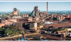
“A blast furnace in operation at thyssenkrupp Steel’s Schwelgern steel mill in Germany, turned 50 years old on 6 February. Known officially as Schwelgern 1 – the Black Giant – the blast furnace is 110 meters in height and has a daily capacity of 10kt of pig iron; it is regarded as one of the biggest blast furnaces in the western world.”
Hydrogen-based Steel Production Project, SALCOS, Receives Gov’t Funding
German steelmaker awarded government funds
Source: Salzgitter
“Salzgitter, Germany’s second-largest steelmaker, has been awarded almost €1billion in government funding for its hydrogen-based steel production project, SALCOS . . . The project will produce around 1.9Mt of raw steel and cut more than 2.5Mt of carbon emissions a year, according to Germany’s economy ministry.”
Foundry Group BIRN Released Its First Sustainability Report
Sustainability Report for BIRN Group
Source: BIRN
“As one of the first in its industry, the foundry group BIRN Group has just released its first sustainability report. The report is an initial step towards a more sustainable business model.”
New Pyrometer for Foundry and Liquid Metal Applications
SPOT MM smart application pyrometer
Source: AMETEK Land
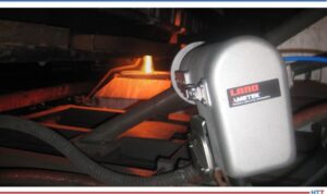
“Liquid steel and metal foundry and tapping operators can now benefit from improved and smart temperature measurements for process control and product quality improvements with the new smart SPOT Meltmaster (MM) application pyrometer from AMETEK Land. The SPOT MM offers a single-sensor solution for liquid metal temperature measurements in foundry and tapping applications. This smart application pyrometer accurately measures tapping stream and liquid steel and metal temperatures independent of surface and condition changes during the process.”
Specialty Steel Provider Joins Steel Manufacturers Association
Mike Williams, President/CEO
TimkenSteel
Source: TimkenSteel
“TimkenSteel has joined the Steel Manufacturers Association (SMA) – the largest steel industry trade association in the United States and is the primary trade association representing North American EAF steel producers. Timken’s president and chief executive offi cer, Mike Williams, has joined the SMA’s board of directors.”
Nucor Steel Berkeley has ordered a new plant for its steelworks from Primetals Technologies
Source: Nucor Steel Berkeley
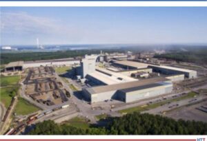
“Primetals Technologies has received an order from Nucor Steel Berkeley, a division of US steelmaker Nucor Corporation, for a new hot-dip galvanising (FVZ) line for the automotive industry. The line will be installed at Nucor’s plant in Huger, South Carolina. Nucor Corporation is the largest steel producer in North America and the largest recycler of materials in the Americas.”
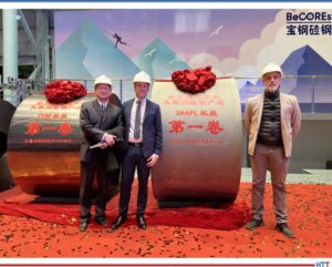
Investing in the production of high-performance electrical steel in Shanghai.
Source: Baowa
“Fives, a leading engineering group with broad expertise in steel processing and technology, has designed and delivered thermal sections for a new annealing and pickling line (APL) and two new annealing and coating lines (ACL). The lines, designed to produce high quality non-grain oriented (NGO) grades for electric vehicle motors, delivered their first coil between December 2022 and February 2023.”
Successful Trials Will Help Manufacturer Reduce Carbon Footprint
Addressing the issue of plastic waste management.
Source: worldsteel
“Integrated steel manufacturer JSW Steel has accomplished a ‘significant breakthrough in environmental sustainability’ by successfully injecting waste plastic into Blast Furnace 3 at its Vijayanagar steel plant following extensive trials.”
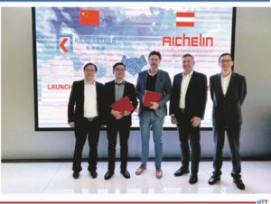
Left to right: Huang Ligang, general manager, Kilnpartner; Zhang Yuejin, Chairman of the board, Kilnpartner; Michael Reisner, CEO, Aichelin Ges.m.b.H.; Christian Grosspointner, CEO, Aichelin Holding; and Fan Xiaochun, CEO, Kilnpartner, after signing the contract.
Source: Aichelin
“The thermal processes used to treat the essential components of Li-ion batteries represent a key technology in this process. These include the cathode as LFP (lithium iron phosphate) or NMC (nickel manganese cobalt) and the active anode material. Only through a highly accurate heat treatment can the crystal structure and morphology of the material be trimmed to “peak performance.” In order to achieve this goal, each manufacturer has its own processes. The common basic requirement is flexible and reliable plant technology, the so-called “kilns.”
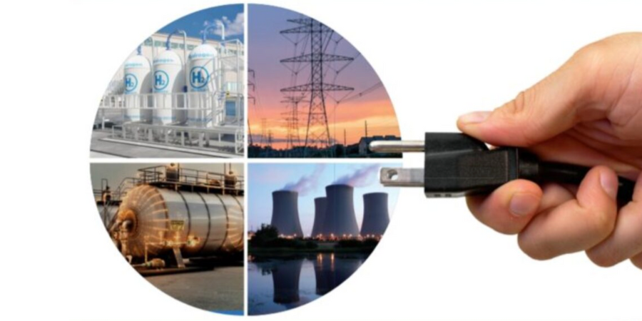
What will the future run on? With growing discontent around current energy sources like natural gas and other fossil fuels, power sources for furnace equipment are due for a makeover. In this article written by Heat Treat Today and media partner Furnaces International, learn from heat treat and energy insiders around the world as they consider current technology investments and future energy opportunities that in-house heat treaters should consider when energizing the future of furnaces.
The four perspectives were written in response to the following questions: 1. What are the short-term and long-term investments for sustainable energy for heat treat furnaces? 2. What role does data and digitalization have in efforts to decarbonize heat treat furnace operations? 3. What other steps can be taken now in heat treat operations to decarbonize heat treat furnaces? 4. What challenges need to be overcome for (North American/European) heat treaters to leverage sustainable technology in furnaces?
This Technical Tuesday article comes from Heat Treat Today’sMay 2023 Focus on Sustainable Heat Treat Technologiesprint edition. If you have any thoughts of your own about furnaces and sustainability, our editors would be interested in sharing them online at www.heattreattoday.com, email Bethany Leone at bethany@heattreattoday.com with your ideas!
1. Wise Heat Treat Decisions for Sustainable Solutions
John B. Clarke Technical Director Helios Electric Corporation Source: Helios Electric Corporation
“Don’t let the perfect be the enemy of the good,” is an excellent principle to follow when heat treaters look at making their operations more sustainable. Particularly when it comes to investments, the first step to reducing carbon output from heat treat equipment should always be to put in place a proper combustion maintenance system. I’ve never seen an investment that did not generate a savings that eclipsed the cost, well within one year. And this not only saves money, it also prolongs equipment life. It’s an all-around good thing to do from any angle.
Another area that heat treaters can improve is efficiently scheduling furnace up-time. All too often, I visit facilities where equipment that is not doing any work remains at operating temperature for a long time, because operators do not know precisely when to introduce more work into the furnace. If possible, idling the furnace at a much lower temperature would save a lot of money.
Programs and scheduling are the low-hanging fruit. Not taking care of them first would be like putting new carpet in the basement before you fix the leak. It’s always best to take care of the fundamentals and make sure you’re doing the best you can with what you’ve got before you go ahead and make those other investments.
In the near term, capital investments are a bit more tricky. There are certainly technologies that will improve efficiency with greater capital investment. These include recuperation or other methods of enhancing heat transfer. For radiant tubes, it could be inserts. The other elements could be pulse firing, particularly in instances where we’re trying to induce an increased rate of heat transfer by creating more mixing within the furnace chamber. These are “on-the-shelf” methods, though they have much longer payback periods, on average.
Switching equipment from gas to electric — or something drastic like that — may not be the answer. We have to focus on the incremental improvement. If I have an investment of 3 trillion dollars to make, it would be wise to first put it towards improving the efficiency of the existing equipment. That one change means fewer tons of CO2 emitted by the end of the year.
Speaking generally, evolutionary technologies must be developed. We have to pursue R&D aggressively, but let’s target the ultimate goal: reduce tonnage of CO2 emitted. That’s the goal. Let’s not confuse the technology or the tool with the ultimate goal.
“If I have an investment of 3 trillion dollars to make, it would be wise to first put it towards improving the efficiency of the existing equipment. That one change means fewer tons of CO2 emitted by the end of the year.”
John Clarke
Source: Pixabay/Geralt
Digitalization Empowers Investments
Digitalization, especially the improvement in data acquisition and analysis, is huge. With higher computational capacity on the controllers on a per furnace basis, we have the ability to start executing real-time analysis on the furnace and potentially implement a thermodynamic model of the furnace and how it’s operating. If I track measurements of total fuel flow, exhaust temperature, and time using the computational powers of a modern PLCs, for example, I can know the core temperature of the piece and exactly when I should pull the piece. That’s digitalization.
The other thing we need to keep in mind is the ability to upload data for analysis. In a sense, this is “the internet of things” (IoT). Let’s say I’m producing 100 tons of steel through a furnace per day. If I monitor the amount of natural gas that system consumes, I know that I have an energy intensity of X cubic feet of natural gas per ton of steel produced. If there’s a deviation, for whatever reason, I know to investigate. It could be the burners are out of tune, it could be something changed in the process, it could be a thermocouple is bad. So, there are a myriad of potential problems that could arise and, if I’m pulling that data, I can know that before I otherwise would.
This modern tendency of collecting and analyzing data is an incredibly powerful tool that should be encouraged and pushed forward. This is an example of the good and not the perfect; we’re trying to take the existing systems and make them more functional and effective.
Digitalization should also be considered holistically — energy is just one part of it, granted a large and expensive part. But it is worth noting that digitalization helps efforts to create safer operations by making systems more consistent.
Next Steps Require a Step Back
As a consultant, I often disrupt facilities, force people to stop thinking about day-to-day activities, and challenge them to think anew about some of these systems. Never underestimate the importance of thinking — and thinking slowly. And thinking requires quiet, but it also requires collaboration, and it requires the plant manager to actually engage with the line operators. Often, we have silos of knowledge — we have maintenance, we have operations, we have management — and they don’t communicate.
Second, in stepping back, make a plan. Prepare the planning process for facility transitions.
Finally, we may always take a step back and ask if a material change to eliminate a heat processing step can be made. In some cases, eliminating the heat processing step entirely will have a big financial impact. Perhaps there are performance specifications that can be met with microalloyed steels that don’t require heat treating! In these cases, be aware that incoming steel costs do not chew up savings.
Source: Pixabay/Martinelle
From a decarbonization point of view, you would need to look at the overall supply chain carbonization and intensity of the mining of these more exotic materials. Depending on the supply chain carbon output of the new material, eliminating heat treating could be a plus on CO2 emissions, though perhaps not a total cost savings.
Challenges Are from Within: Interest Rates and Internal Investment
In North America, rising interest rates mean that we are somewhat in a catch-22. When interest rates are low, investments into changing equity or the treasury level of the companies typically occur versus investing in the core business. Now that interest rates are higher, companies actually may start looking at optimizing the actual performance of their individual company. But too many people are too aggressively pursuing figures, caring more about the return on equity versus focusing on the core performance of the operations. Enterprise is often given a capital budget of X when, in reality, the capital budget really should be based on a two-year hurdle rate. Management wants to invest in the enterprise on all projects that will return 30% on internal investments because they see large corporations making major investments and other businesses are lucky to earn half that kind of return
One of the impediments is simply convincing management and decisionmakers on the validity of internal investment. Your enterprise represents an internal investment opportunity that exceeds the return you’re likely to receive from an acquisition of a new enterprise. I know that runs counter to some of the thinking prevalent in the market today, but it is important to point out. I am an “internal return on investment” kind of guy, so I speak with a bias. But time and time again, I see opportunities go unexecuted because they don’t meet a preconceived budget. If your objective is to make money, invest it to maximize the return.
Our national laboratories and our universities throw out a lot of great technology. Some of it is ready for primetime, some is in the nascent of condition and needs more investment and time to mature. I’m not sure we have enough enterprises to partner with these design and research groups and commercialize the ideas. It’s in this “valley of death” — where the basic technology has been developed and proven to be viable, but the commercialization and the manufacturing is lacking — that we need to overcome and increase enterprise. Particularly in the heat treating industry, there is a problem of fewer “catchers” who will partner with and develop new technologies that could aid in decarbonization. This is because there have been a lot of acquisitions. If you look at the membership of IHEA, it’s the same people and the same businesses but there are fewer people. Everyone is buying everybody else. Larger corporations tend to be less likely to take the risk on a piece of technology that won’t immediately pay back. They also have a lot of “not-invented-here” issues as well.
One solution is for the Department of Energy to invest. Though they already do this, even greater investments into brokers and advocates are necessary to pick up this technology and pass it through instead of simply trying to contact people. During U.S. President G.W. Bush’s time, the Department of Energy had a “Save Energy Now” program during a natural gas spike. The program sent people, like myself, around to plants to run analyses for free. The program was extremely valuable because it gave enterprises motivation. I did speeches at many different automotive plants and participated in collaborative events as part of that program. I think refunding that program and refocusing on something like that would be beneficial.
My idea of the way forward is half technical and half promotional, demonstrating to people that there is another way. That is an effective role for government. I would like to see them redo that. It would be a different emphasis.
About the author: John Clarke is the technical director and owner of Helios Electric Corporation, a company based in Fort Wayne, Indiana, that specializes in energy and combustion technologies. The depths of his knowledge on energy and combustion topics can be seen in the technical articles and columns that John has contributed to Heat Treat Today's Combustion Corner.
Philippe Kerbois Global Industry Manager for Glass AMETEK Land Source: LinkedIn
For the industrial context where the improvement of productivity, energy efficiency, and environmental performance is increasingly essential — especially for temperature furnaces — the coupling between the hybridization of furnaces integrating different technologies becomes a solution to be seriously taken into account.
During the last century, with the appearance of energy and emission constraints, the steel and glass industries used for the most part the same energy saving techniques with heat recovery on flue gases for preheating combustion air, thus reducing energy consumption by 20%–30%. In the 1980s, regenerative burners arrived. Based on the same principle of preheating air — though at higher levels — regenerative burners improved the energy efficiency of the installation, but also increased NOx emissions. This is clear for many large industrial companies in steel, glass, and cement, for whom the industrial electric furnaces reduce emissions and risks, and require little maintenance. But the electrification of existing furnaces, which often run on gas, is far from obvious as fired furnaces are still numerous all over the world.
Today’s Solutions: Which Is the Way Forward, Gas or Electric?
Today, what can be done to improve energy efficiency? Improving energy efficiency in glass or steel reheat furnaces can be achieved by implementing various strategies. The approach for short term investments needs to be pragmatic. It is possible to implement better practices and technologies on any furnace.
We can point to some general short-term steps that can help improve energy efficiency:
Conduct an energy audit
Insulate the furnace
Upgrade insulation
Install energy-efficient motors and drives
Implement energy management systems
Optimize combustion
Use waste heat recovery systems
Upgrade to more efficient equipment
Use advanced process control systems
By implementing these strategies, it is possible to significantly reduce energy consumption and improve the energy efficiency and emission of a fired glass furnace. However, it is important to note that the specific strategies used will depend on the furnace’s operating conditions.
When heat treaters step back from burner-focused solutions and short-term plans, the next question is often: Do we need to change or upgrade our equipment? And is electric the only wise way to go when seeking energy efficiency?
The choice between gas and electric furnaces depends on a variety of factors, and there is no one-size-fits-all solution. It is important to consider the specific needs of the application and weigh the costs, energy efficiency, and environmental impact when making a decision. One might consider the following:
Gas furnaces are generally less expensive to purchase and install than electric furnaces. However, the cost of operating a gas furnace can be higher due to the fluctuating price of natural gas. Electric furnaces, generally more expensive to purchase and install, typically have more stable operating costs.
All the relevant references of use of electrical furnaces in the past were related to lack of flexibility especially in glass when changing the quality and types of glass or colors. This could cause some issues where flexibility is needed for production operations.
Considering the environmental impact, gas furnaces produce carbon dioxide (CO2), and other greenhouse gases that contribute to climate change. Electric furnaces do not produce direct emissions, but their indirect emissions depend on the source of the electricity used to power them. If the electricity is generated from renewable sources such as wind or solar power, then electric furnaces can be more environmentally friendly.
Tomorrow’s Possibilities: Looking Beyond the Short-Term
In order to move into the future, education about the present is key. Focusing on environmental impact looks different regionally, and the lack of awareness and education of local teams needs to be considered as well. Regulations and standards related to emissions and energy efficiency could be regulatory barriers: What is true in China or India is not necessarily fit for Continental Europe, the U.K., or U.S.
From region to region, the compliance with these regulations can be a significant challenge for heat treaters. Meeting these requirements may require significant investments in new technology or modifications to existing systems where electric furnaces are direct impact on the direct emissions.
Many heat treaters or glass manufacturers may not be aware of the benefits of sustainable technologies or may not fully understand how to implement them. Providing education and training sessions on sustainable technologies can help overcome this challenge. Data and digitalization play a critical role in efforts to decarbonize heat treat furnace operations. Here are some ways in which data and digitalization can contribute to decarbonization:
Resistance to change
Real-time monitoring
Predictive maintenance
Optimization of energy consumption
Supply chain optimization
Carbon accounting
Investing in renewable energy sources such as solar or wind power can provide long-term energy savings and reduce greenhouse gases, but for most heat treaters, these are monumental decisions. The approach to long terms investments needs to be pragmatic focusing on renewable energy sources when available near the plants where a power grid is available.
Any end-users can work with experts in sustainable technology to identify opportunities and develop strategies for implementation of Industry 4.0 technology using SCADA systems and predictive tools. It may also be helpful to collaborate with other companies or industry groups to share best practices and insights. Government incentives or funding programs may be available to help off set the costs of implementing sustainable technologies.
“Investing in renewable energy sources such as solar or wind power can provide long-term energy savings and reduce greenhouse gases, but for most heat treaters, these are monumental decisions. The approach to long terms investments needs to be pragmatic focusing on renewable energy sources when available near the plants where a power grid is available.”
Philippe Kerbois
Source: Manny Becerra
In conclusion, data and digitalization are critical tools in efforts to decarbonize heat treat furnace operations. By providing real-time monitoring, predictive maintenance, energy optimization, supply chain optimization, and carbon accounting, data and digitalization can help heat treaters to reduce their carbon footprint and transition towards more sustainable operations, including electric furnaces.
About the author: Philippe Kerbois, previously Regional Sales Manager EMEA – Glass for AMETEK Land, has over 20 years’ experience in high value, complex technical solution sales with specialties in glass, renewable energies, automotive, water filtration, energy production, gas turbines, automation, building automation and oil and gas. He holds a degree in mechanical engineering (Diploma of Higher education) associated to ESTACA degree (Aeronautics and Automotive Engineering school).
A Low Carbon Future Could Be One Investment Cycle Away
Peter Sherwin Global Business Development Manager Watlow Source: LinkedIn
It is helpful to put some numbers around sustainability. Recent reports from the IEA (International Energy Agency) indicate we need to improve energy intensity by around 4% between now and 2030 and about 3% from 2030 to 2050 to be close to achieving net zero goals. The 4% level is double what was achieved over the last decade.
Sustainable investments in heavy industry (steel, cement, chemical) have already started. Blast furnaces and cement kilns last for around 40 years, and 2050 as a net zero target is now less than one investment cycle away. North America is leading the way by investing in electrifying the industry via electric-arc furnaces which aid in cleaning up an industry that has had a high dependency on coal. Newer technologies, including the electrolysis of steel, promise alternative ways of low-carbon manufacturing, but this technology will only likely provide significant production quantities after 2030.
Miranda Pizzella Engineering Manager Watlow Source: LinkedIn
At the lighter end of the industry, industrial furnaces for heat treatment may generally have a slightly shorter lifecycle. Still, investment decisions in new capital equipment today will directly impact the industry’s emission profile over the next 30 years. Therefore, this long-term investment needs to consider the potentially changing energy landscape.
At face value, in many places in the U.S. and Europe, the ratio between gas and electric pricing would steer investment towards gas-fired furnaces if the only criteria were running costs (ignoring heat treat equipment that is only electric-fired, e.g., vacuum furnaces). This cost advantage is starting to change with increasing carbon taxes, potential disruption of fuel supply (currently in Europe), further stringent NOx emission requirements and continued supply challenges for complex gas trains.
Combustion burner design can significantly impact the energy efficiency of a furnace. Straight-through tubes are on the scrap heap, and recuperative and even regenerative burner systems now aid efficient energy use. In addition, dual-fuel burners that can work on hydrogen or natural gas are becoming available. Although the economics of carbon-free hydrogen remains a constraint to its heavy use, this is expected to change over time, with innovations to improve the hydrogen landscape post-2030.
Andy Selvy Chief System Designer Watlow Source: LinkedIn
There is a significant amount of research in next-generation elements for electric furnaces. The element material composition, desired life, and manufacturability are all areas currently being explored. In addition, the controllability of an electrical element is significantly better than its combustion alternative, and unique algorithms are in development to take advantage of this to aid efficient processing.
More Digitalization, Greater Efficiency
Today, heat treat operations lack visibility and access to critical process data, leaving operators reactive when mitigating performance factors such as utilization time, quality, yield, and energy consumption. Data and digitalization provide many opportunities to improve efficiency and reduce overall energy consumption within furnace operations. Poor thermal uniformity can lead to scrap and rework of material, which both result in excess energy consumption.
Process drift can also cause more energy to be consumed over time to achieve the same operational results. Examples of process drift include drift from target program set points, processing times, nominal values such as desired heater power output and thermal uniformity values. Lack of visibility to process drift can create rework when specifications are missed the first time or potentially result in a scrapped batch.
“Through proper data collection and analytics combined with thermal systems expertise, problems can be overcome, which not only reduce carbon emissions but also improve productivity and profitability for heat treaters.”
Source: Adobe Stock/panuwat
It is important to recognize that data can be a powerful input for decision making to improve process efficiency. However, data alone is not enough to act to create significant improvement. To utilize data for process improvements, it must be delivered in a way that is easily consumed and creates clear action to be taken. Thus, it is important that we combine data with subject matter expertise to contextualize and transform data into actionable insights. For example, Watlow and Eurotherm have combined their expertise to enable value creation in collecting, interpreting, and transforming data into actionable insights that can be put in the hands of the operators when they need it, where they need it.
Through proper data collection and analytics combined with thermal systems expertise, problems can be overcome, which not only reduce carbon emissions but also improve productivity and profitability for heat treaters.
Steps Towards Digitalization
A heat treater’s first step towards digitalization should be to work with suppliers to understand what digital solutions are being offered. Watlow and Eurotherm have pooled their skills to find ways to offer better solutions. Driving towards data-driven decisions impacting process performance and energy consumption is relatively simple and gives operators an opportunity to take proactive measures, and it also lays the foundation for future investment through data-driven performance trade-offs and insights.
At a thermal-loop level, find suppliers that are focused on improving the performance of electric-fired furnaces from the transformer to the element to the power controller and process controller/recorder.
Consult your supplier about recording strategies and leveraging power data. First, record data in a format that doesn’t create data islands but protects the integrity of the raw data. And second, leveraging power data in real-time allows you to share information between furnace zones or different furnace equipment, which can help lower peak-power demands by scheduling when the individual SCR power controllers fire.
Recently, we launched a new 14.0 pilot service program which provides data insights to enable peak performance. Tracking process performance through insightful data, correlations related to process inefficiencies can be established. Energy consumption improvements to the process can be made such as identifying and mitigating inefficient combustions.
Consider the Cost
Top of the list of challenges to adopting sustainable technologies is the ongoing cost conversation — the cost of gas versus electricity. The gas and electric prices do differ significantly across all regions. However, this equation is changing in even the most attractive gas districts. Once you add on rising compliance costs to emissions plus the ramp of renewables, this will ultimately favor an electric future.
In the U.S. and most parts of Europe, energy has been plentiful and reliable for a long time. The U.S. has also enjoyed decades of relatively low costs of all forms of energy. Contrast this with some regions of Asia where weekly and sometimes daily power interruptions still occur. As a result, there is a different mentality and behavior around resource use and abuse.
The higher price of energy in Europe, and the current spike in the Ukraine conflict, have started to impact behaviors. For example, we now see customers with a mid cycle refurbishment of a furnace looking to evaluate a move from gas to electric.
About the authors: Peter Sherwin is a global business development manager who is passionate about offering best-in-class solutions to the heat treatment industry. He is a chartered engineer and a recognized expert in heat treatment control and data solutions. He has lived and worked in the U.K., India and the U.S.
Miranda Pizzella holds a Ph.D. in aerospace engineering with a concentration in thermal-fluid science from Parks College, Saint Louis University. Miranda is leading the company’s Industry 4.0 strategy and has accelerated the adoption of related technologies to transform the business through leveraging data to create more value. Miranda currently leads the computational engineering team and the Industry 4.0 development team.
Andy Selvy holds a B.S. in ceramic engineering from Missouri University of Science and Technology and an MBA from Maryville University. In his current role as a chief system designer, he leverages 20 years of solving complex thermal system problems to help grow new technology into scalable products and services.
A Middle Way: Hydrogen in Combination with Fossil Fuels
Stuart Hakes Chief Executive F.I.C (UK) Limited Source: LinkedIn
There are a number of things to be taken into consideration for “energizing the future of glass furnaces.”
In the short-term, it is possible to add electric boost to an operating furnace on-the-run, to reduce the amount of fossil fuel being used. However, the proportion of electrical energy that can be installed, relative to the amount of gas currently being used, makes a very small difference to the CO2 emissions. The reason being that approximately 30% of the total energy is used for “holding heat,” i.e. to keep the structure warm. A fair part of this holding heat is required in the regenerators which pre-heat the air and although 1 kW of electricity should save 2 kW of fossil fuel, in reality with regenerative furnaces it is difficult to get close to this figure. Anything from 1.3-1.8kW is the norm.
The next stage, which is a small incremental investment, is to go to superboost. Superboost, again, is not very effective unless the amount of air and gas going through the regenerators can be reduced, which is nigh on impossible on end-port furnaces and difficult on cross-fired furnaces. Therefore, the other option is to add hydrogen to the natural gas stream and this can only be done by Government edict. But it is relatively easy to do with the existing burner set up, however, this is only feasible up to a maximum of 30% with current technology, before major technical issues are encountered. There are particular capital requirements needed for handling large amounts of hydrogen.
Less Fossil Fuels, More Hydrogen and Electrification
The proper progress for glass furnaces is to convert from fossil fuel, air/gas, regenerative furnaces to oxy-fired. This will give an improvement in thermal efficiency which will have a small impact on CO2 emissions but not significantly. The only way long term to have a major impact is either hydrogen firing or all-electric. In both cases a considerable amount of investment is required. However, the opinion of the author is that hydrogen will be a premium fuel and the only fuel in many industries and therefore if alternatives are available for the glass industry these will more likely to be adopted.
Source: POLEX/Adobe Stock
The issues regarding the safety of using hydrogen presents huge difficulties in terms of mitigating risk. We must also consider that burning hydrogen increases the level of foam in a glass furnace, which is detrimental to melting efficiency a the refining of glass. Whilst these two factors may be overcome, there is the final issue that currently, no refractories exist that can withstand the product of combustion of a hydrogen flame, which is superheated water, possibly at 2400°C (4352°F). This is a major problem for the industry to overcome.
For this reason the author believes that a hybrid furnace with 80% of the melting energy from electric and 20% from some kind of top heat, could be electric heating, or could be hydrogen flame or some other alternative fuel, is the answer. The issue with going all-electric is that a massive investment is needed in the grid reticulation system as well as finding sources to generate green electricity to cover the requirements. This is a major issue for the Government to address as many other industries will need to electrify as well.
The major challenges for hydrogen are as enunciated above. In particular, the safety issue of hydrogen is a huge change, the other issue is that 3 times the volume of hydrogen is required than that of natural gas meaning reticulation systems will have to be changed. And finally, in container forehearths where air/gas mixtures are used for conditioning the glass, this is not possible with hydrogen and so the only way to decarbonize this process is to go all-electric. This technology is currently available and already shows anything between 80-90% both energy reduction and cost reduction. As I stated before, the only other major challenge is the amount of electricity available for industry and the public at large, in order to make these changes.
Short-Term Digitalization Efforts, Investments, and Impact
Big data and digitalization can assist decarbonization efforts, but this requires no more than what is currently available for fossil fuel fired furnaces. Capital investment is low, and the technology is available now.
About the author: Stuart Hakes has 58 years in the glass industry. He studied Glass Technology in England and worked in the United Kingdom with container plants affiliated to the O-I Group. Stuart joined F.I.C. (UK) Limited as CEO in 1999 and has been there ever since.
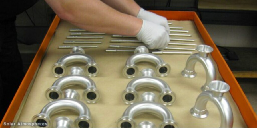
Recently, Solar Atmospheres Eastern PA commissioned a new 25,000 square foot brazing facility aimed at high-volume, high-quality braze production. The facility features six vacuum furnaces dedicated to brazing, including an all-metal hot-zone furnace designed for brazing stainless steel to copper with silver and gold-based braze filler metal (BFM).
The heat treater specializes in the brazing of high-value components utilizing filler metals based on nickel, silver, gold, and copper. The new state-of-the-art production facility has 4,000 square feet of climate-controlled workspace, where technicians assemble and inspect parts, ranging from tiny capillary-tube manifolds to large land-based gas turbine blades. The operation incorporates increased capacity for helium leak testing and pre-braze tack welding of braze assemblies.
“With Nadcap accreditation and AS9100 registration, our new facility operates as one expects from the Solar brand,” states Chip Lahneman, general manager of Brazing at Solar. “The investment in our new facility demonstrates Solar’s commitment to meeting our customers brazing needs, now, and in the future.”
Find heat treating products and services when you search on Heat Treat Buyers Guide.com