By Jose Miguel Equihua Toral, Head of the New Projects and Development, BOINSA Mexico and Manager, InTech NDT, USA.
Nondestructive testing (NDT) techniques have been used exclusively to detect defects in structures and components after they have been manufactured. To protect public safety and security, it is imperative to test parts efficiently and ensure their quality. Nondestructive evaluation, like ultrasonic backscattering, serves an important role in this area.
This informative piece was first released in Heat Treat Today’s April 2025 Annual Induction Heating & Melting print edition.
Introduction
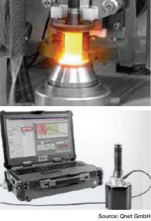
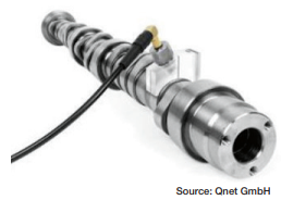
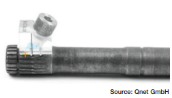
Figure 1b. UT backscattering testing (bottom)
Induction hardening is a critical process in manufacturing automotive, agricultural, and aeronautical components, such as crankshafts, camshafts, constant velocity joints, and axle shafts (Figure 1a). The procedure for the evaluation of metallurgical characteristics is carried out in the laboratory and is destructive testing (Bernard, “Methods of Measuring Case Depth in Steels”). This means the component will be unusable. Additionally, this procedure is time-consuming, expensive, and cannot be integrated into the production line. Over time, the industry has sought faster and more efficient methods to evaluate metallurgical characteristics, such as eddy current testing, magnetic methods, and ultrasound. Having the capability of monitoring material properties after each key process can help minimize the cost of processing out-of-specification material. A combination of nondestructive testing methods can help to guarantee the quality of induction heat treatment operations (ASM Handbook, vol 4c).
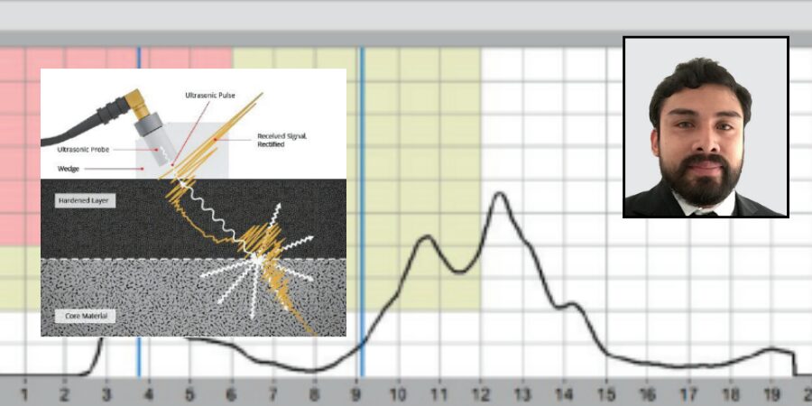
Ultrasonic methods, for example, can be used to determine microstructural differences in metals. For this, contact testing with pulse-echo technique is used. For inductive-hardened parts, the ultrasonic backscattering method works because the hardened layer (martensite) is almost transparent to ultrasonic waves (in range of 20 MHz), while bulk material (ferrite-pearlite) scatters ultrasonic waves very strongly.
In this article, we will address the use of industrial ultrasound applying the backscattering technique, which offers a direct determination of the depth. This method is simple and does not require prior calibration to evaluate the components (Figure 1b).
The Ultrasonic Backscattering Technique
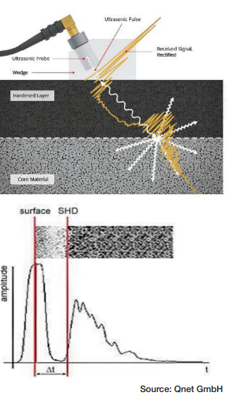
Figure 2b. Time-of-flight measurement (bottom)
Iron crystals exhibit notable acoustic anisotropy, meaning the acoustic velocity (c) varies depending on the direction of travel within the crystal. Grain boundaries represent transitions between crystal structures with varying orientations. The resulting variation in impedance causes the ultrasonic pulse to scatter at the grain boundaries. The ultrasonic technique for measuring hardness depths (SHD) utilizes this grain boundary scattering effect. This technique is known as the ultrasonic backscattering method (Kruger et al., “Broadband Ultrasonic Backscattering”).
The ultrasonic backscattering method for hardness depth testing relies on finding the ultrasound frequency that does not scatter at the fine-grained hardened microstructure of the outer layer but at the coarse-grained core material (Figure 2a). The different scattering properties from the varied grain sizes of the hardened surface layer and the core material are seen in the backscattering measurement. The connection between scattering and the material’s grain size is utilized to produce a detectable backscattering echo when the ultrasound penetrates the core material.
The depth (SHDUS) of the interface can be determined using the time (t) it takes for the sound pulse to reach the scattering interface, the angle of the shear wave (βT), and the velocity (c) of the shear wave in steel. Therefore, the following equation is relevant for a flat shape:
SHDUS=1/2∙c∙t∙cos∙βT
Based on this equation, the acoustically measured surface hardness depth (SHDUS) is always found before the sound exit point of the probe wedge. To guarantee an accurate measurement of this location during destructive testing, this distance (A) must be calculated. The next equation is used for a plane geometry:
A=1/2∙c∙t∙sin∙βT
The backscattered ultrasonic amplitude depends on the actual gradient of the microstructure. In the transition zone, grain boundaries, grain size, and second phases change the acoustic impedance value discontinuously, depending on the ultrasonic frequency. Different backscattering signals in the hardened and bulk material occur (Yanming Guo, “Effects of material”). Th ese amplitude characteristics can be used to evaluate the case depth by using simple time-of-flight measurements (Figure 2b). Contact testing is generally done by using portable equipment, using a contact wedge where the transducer is mounted to be inclined at a certain angle, and shear waves are emitted into the component. Ultrasonic backscatter takes place at the surface of the component due to surface roughness and results in the return of the energy to the transducer (first echo). Ultrasonic energy enters the hardened surface layer made of fine martensitic structure, and thus, no scatter of ultrasonic waves takes place in this region. However, when the shear waves reach the transition zone where martensitic structure is gradually converted into ferrite-pearlite structure, which has a larger grain size, once again energy is scattered at the grain boundaries, and the transition zone backscatter forms the second echo. The difference in time-of-flight of these two echoes is proportional to the case depth of the component.
Technical Requirements
Technical requirements for testing hardness depth using the ultrasonic backscattering method will produce optimal results in the following conditions:
- The test parts should be induction-hardened.
- The test parts must be forged, not cast.
- There is minimal or no microstructure present between the hardened martensitic microstructure and the core material.
- The grain size of the core material is significantly larger than the grain size of the hardened microstructure, leading to considerable backscattering of shear waves at a frequency of 20 MHz.
- The minimum hardness depth that can be measured is 1.2 mm. Smaller hardness depths need special considerations, such as adjustments to the wedge design.
Practical Correlation Between NDT and DT
Destructive hardness depth testing is a method to determine the thickness of the case depth of hardened parts. In the process, the parts are destroyed, or their surface is altered rendering each tested part unusable. Hardness depth profiles are usually determined by using the Vickers test to measure the hardness of a reference sample at different points in a line from the surface to the core.
If you compare the acoustically measured surface hardness depth SHDUS with the surface hardness depth measured with destructive methods SHDDT, you will see a basic difference: Independent of the hardness limit and the minimum hardness, the acoustic testing always determines the depth of the core material that has not been affected by the hardening process. As a consequence, this value tends to be slightly higher than the surface hardness depth measured with destructive methods SHDDT. This difference can be compensated by means of a correction term ΔT (“Off set”):
SHDUS = SHDDT – ΔT
In the case of hardness curves with rapidly decreasing hardness values just above the interface, the transit time is measured at 20% of the height of the backscattering signal’s amplitude, and the results of the acoustic and the destructive hardness depth tests will match. The reason for this is the slightly shorter sound path in the marginal ray of the divergent sound field, which induces the backscattering echo.
If cases occur regularly in which the hardness curve deviates significantly from the characteristics, reference tests must be conducted to determine the correction factor ΔT. Reasons for this could be material and/or process related. The calculated correction factor can then be integrated in the respective test task as a test parameter.
Technical Description and Measurement Highlights
The manual device includes a four-channel ultrasonic board managed by a software package for program settings, signal processing, reporting, and overall quality assurance requirements. The parts are put together in an industrial notebook meant for tough industrial settings. The probe systems allow testing of components with complex shapes. The wedge of the probe system is adjusted to fit the geometry of the specific test location. Testing can be done before or after machining.
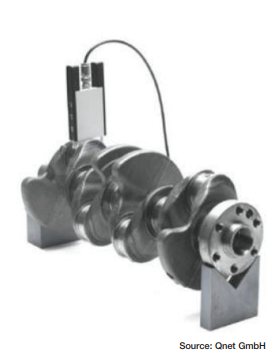
The primary cause of measurement error is the evaluation of surface position; the shape of the surface signal relies on proper coupling and the operator’s skill. Another source of error is the placement of the marker that indicates the time-of-flight when the pulse hits the interface. The sharper the signal rises, the less the error. Therefore, a shear wave angle as low as reasonable is employed, and scanning in the direction of decreasing SHD is advised. Achievable accuracy of better than ±0.1 mm is possible for standard parts with high-quality surfaces. Nevertheless, the operator must monitor the “good” shape of the A-scan during data collection. Accuracy based on microindentation hardness profiles compared to the backscatter method is slightly lower, estimated at ±0.2 mm on average, based on the material microstructure (Bogaerts et al., “Surface Hardness Depth Measurement”). We are able to test different geometries like crankshafts (Figure 3), camshaft s (Figure 4), tulips (Figure 5), and barshafts (Figure 6), to mention some components.

Feasibility Testing
Situation: During induction hardening, an unanticipated variation on the case depth was detected on the shaft of an axle bar (Figure 7). We were requested to examine the case depth in this important area using a P3123 Hardness Depth Tester to find out if the case depth met specifications.


Results: During the testing, we noted the case depth was insufficient compared to the minimum required case depth of 5.5 mm. This meant all induction hardened parts made before the discovery had to be paused while a complete check of the case depth was performed. All axle bars hardened after the discovery were analyzed (Figure 8), starting with the most recently hardened parts. Case depth was also evaluated by making a microindentation hardness profile in the hardened area, showing a case depth consistent between ultrasound readings with the P3123 and the destructive testing measurements. In Figure 9, we can observe the measurement of the out of specification case depth, and in Figure 10, we have the measurement within specification case depth.
Hardness depth testers are used for optimizing production parameters, reducing downtimes after inductor changes, fast production control, and quality management. The techniques discussed in this article offer the technical advantages to ensure quality assurance for both steel and induction hardened components. Feasibility testing is required, which can be performed with prompt review of the ultrasound behavior in components.


References
ASM International. ASM Handbook Volume 4C: Induction Heating and Heat Treatment. 2014.
Bernard, William J. “Methods of Measuring Case Depth in Steels.” Steel Heat Treating Fundamentals and Processes (2013): 405-416. https://doi.org/10.31399/asm.hb.v04a.a0005795.
Bogaerts, Mike, Michael Kroening, Paul Kroening, and Tobias Mueller. “Surface Hardness Depth Measurement Using Ultrasound Backscattering.” AM&P Technical Articles 177, no. 8 (2019): 58-62. https://doi.org/10.31399/asm.amp.2019-08.p058.
Guo, Yanming. “Eff ects of material microstructure and surface geometry on ultrasonic scattering and fl aw detection.” Dissertation, Iowa State University, 2003.
Kruger, S.E., J.M.A. Rebello, and J. Charlier. “Broadband Ultrasonic Backscattering Applied to Nondestructive Characterization of Materials.” IEEE Transactions on Ultrasonics, Ferroelectrics and Frequency Control 51, no. 7 (2004): 832-838. https://doi.org/10.1109/tu c.2004.1320742.
About The Author:

Head of New Projects and Development
BOINSA Mexico
Manager,
InTech NDT, USA
Jose Miguel Equihua Toral graduated as a mining engineer from Guanajuato University and obtained his Master’s Degree in Engineering from the National Technology Institute of Mexico. He currently works as head of the new projects and development department of BOINSA de Mexico, involved in technological and operational advances in the design, manufacture, and repair of induction coils, as well as advances in the application of non-destructive testing methods for the quality assurance of components for the automotive, agricultural, and energy industries. This experience has led to the formation of InTech NDT, to serve the U.S. market.
For more information: Contact Jose Miguel Equihua Toral at miguel.equihua@intech-ndt.com.