What makes the geometry of a part “complex”? With the increasing use of AM and 3D printing for parts along with typically complex parts, heat treaters in many industries must acquire the equipment and technical know-how for precise applications.
This Technical Tuesday article is compiled from Heat TreatTodayarticles and industry news releases. Email Bethany Leone at bethany@heattreattoday.com or click the Reader Feedback button below to chime in on the topic.
What Are Complex Geometries?
Contact us with your Reader Feedback!
Complex geometries in industrial parts are often defined by their intricate patterns and structures, which entail specialized heat treat processing. As Inductoheat describes in a case study with Stellantis, “Many times, complex geometries of components are linked to intricate hardness patterns and specific requirements for magnitude and distribution of residual stresses.”
Heat Treat Equipment for Processing Parts with Complex Geometries
Be it for highly customized medical implants or for engine components in the burgeoning electric vehicle industry, complex geometries need to heat treated carefully. Fasteners in the medical device industry can be quite intricate and susceptible to creep or other dimensional changes; one method heat treating these parts — particularly titanium alloy parts — would be in a vacuum furnace. In vacuum and in hot isostatic presses, the environment allows for complex geometries that are 3D printed to be made into a unified whole piece. “Heat conduction can be carefully monitored [in induction heating coils] to confirm that an overheat condition does not occur at the target temper areas,” making induction a key candidate for heat treating your parts with complex geometries (“Tempering: 4 Perspectives — Which makes sense for you?“). To accommodate the complexities of certain parts, designing an induction coil for the desired case hardening may entail simulation to “[predict] coil heating, which altogether results in a longer coil lifetime,” (“Simulation Software and 3D Printers Improve Copper Coils”). For more on induction coils, check out this article by Dr. Valery Rudnev.
Suffice it to say, there is a great diversity of heat treatment options to explore when it comes to identifying the appropriate equipment for your application.
What Processes Are Used in Heat Treating Complex Geometries?
Perhaps you have all of your equipment needs necessary for heat treating your parts with complex geometries. Are you completing your heat treat processing in the most technically sound manner? Check out the following excerpts that speak to processing complex geometries.
“[Forging] at elevated temperatures enables reaching high strains and forming complex geometries in a single stroke. Additionally, thermal and mechanical influence during the forging can lead to improving local mechanical properties and the quality of the resulting joining zone.” (“Thermomechanical Processing for Creating Bi-Metal Bearing Bushings“)
“In some cases, such attempts result in a component’s geometries that might be prone to cracking during heat treating or might be associated with excessive distortion . . . . The subject of induction hardening of complex geometry parts (including but not limited to gears, gear-like and shaft-like parts, raceways, camshafts, and other critical components) is also thoroughly discussed, describing inventions and innovations that have occurred in the last three to five years.” (“Heat Treat Training Benefits Stellantis“)
“LPC [low pressure carburizing] with gas quenching can be an attractive option for distortion prone complex geometries as the cooling rates are slower than oil quenching; however, given the slower cooling rate, it becomes very important to choose a higher alloyed steel that will achieve the desired hardness.” (“Elevate Your Knowledge: 5 Need-to-Know Case Hardening Processes“)
Complex Geometries In the News
See how your peers are solving complex geometries needs in these real-life partnerships with industry suppliers. From additive manufacturing (AM) and precision manufacturing parts to heat treat technology, maybe your company is next to leverage manufacturing equipment to “wow” the industry.
Discover expert tips, tricks, and resources for sustainable heat treating methods Heat TreatToday’srecent series. And, if you’re looking for tips on combustion, controls systems, or induction in general, you’ll find that too! Part 2, today’s tips, digs into energy and electricity. We’ve added another resource towards the end of today’s post to further enrich your knowledge of induction heating.
This Technical Tuesday article is compiled from tips in Heat TreatToday’sMay Focus on Sustainable Heat Treat Technologiesprint edition. If you have any tips of your own about induction and sustainability, our editors would be interested in sharing them online at www.heattreattoday.com. Email Bethany Leone at bethany@heattreattoday.com with your own ideas!
1. Maximizing Energy Efficiency of Vacuum Furnaces
Contact us with your Reader Feedback!
The use of AC to DC transformers is an energy-efficient innovation that can significantly lower energy consumption of the heating system. Typically, a system uses alternating current as the primary source, which fluctuates output during each half cycle. Using AC to DC transformers limits these fluctuations, reducing the amount of energy used. Furthermore, transformers operate at optimal efficiency when under a reduced load – i.e., less than 70% output in steady-state heating – rather than ramping up to the full operating temperature. Another advantage of the DC-type transformer is that its operating power factor is very close to 1.0, which lowers the utility company’s calculation of peak demand surcharges
Try power feedback for your electric heating elements. Power feedback is ideal for variable resistance heating elements. Kilowatts are used as the unit of control, rather than just current or voltage.
Conserving energy is not only good for the environment, but it can mean more money in your pocket and less downtime. Here are three tips to improve furnace efficiency with diagnostic technology:
Do you have tight and secure terminal connections? Poorly connected power cables waste electricity and can cause fires. An SCR power controller monitors terminal temperature changes and will alert you before failures happen. It also monitors heat sink temperatures and ensures the control’s cooling fan is working properly.
Do you have a heater-break alarm? Heating zones typically have multiple heating elements, wired in parallel. A broken element is difficult to detect and will impact the heater’s circuit, reducing the power of the process. This can waste energy and affect product quality. A heater-break alarm will alert you to a failing heater circuit.
Do you pay high electricity bills? You could benefit from a factory load management system. It’s now possible to limit peak current loads and power usage across your factory and multiple furnaces. These systems communicate by sharing important power-demand information and providing more effective power distribution.
A connected and automated factory network saves electricity and improves operational efficiency by establishing powerful furnace management systems.
After absorbing today’s tips, you may want to take one step farther to read up on induction heating. Take a look at “Why Induction Heating is a Green Technology” to help broaden the horizon.
Find heat treating products and services when you search on Heat Treat Buyers Guide.com
Discover expert tips, tricks, and resources for sustainable heat treating methods Heat Treat Today's recent series. And, if you're looking for tips on combustion, controls systems, or induction in general, you'll find that too! Part 1, today's tips, digs into cleaning and maintenance
This Technical Tuesday article is compiled from tips in Heat Treat Today's May Focus on Sustainable Heat Treat Technologiesprint edition. If you have any tips of your own about induction and sustainability, our editors would be interested in sharing them online at www.heattreattoday.com. Email Bethany Leone at bethany@heattreattoday.com with your own ideas!
1. Maintenance of Induction Coils Used in Hardening Applications
Contact us with your Reader Feedback!
Soap and hot water will remove sticky quench and debris. Source: Induction Tooling, Inc.
How should you maintain induction coils used in hardening applications? Elbow grease — a little goes a long way. After each use, a simple solution of soap and hot water will remove sticky quench and debris. Scrub hardened dirt with a Scotch-Brite pad. Check for pitting, arcing, and insulator damage. If all is good, use a hot water rinse, and it’s ready for use. If the inductor is to remain on the machine for an extended period, it is advised to wash it and the associated bus daily. Check for damage. Following this simple procedure will reduce business waste.
As industry tries to become more “green,” a number of companies are switching from lubricants that are petroleum or mineral oil-based to water-based (“aqueous”) lubricants instead. However, some of these companies then make the mistake of not changing their degreasing fluids that they use to remove these lubricants prior to their next processing operations, and stay with their standard degreasing fluids, such as acetone or alcohol, which are not effective at fully removing water-based lubricants. Instead, they need to run tests to find an appropriate alkaline-based degreasing fluid for such water-based lubricants, since alkaline-based degreasers will be effective at removing such lubricants. Commonly available dish-detergents (alkaline-based) have been shown to be highly effective for such use.
Nikola Tesla afirmó: <<Si quieres descubrir los secretos del universo, concéntrate en la energía, la frecuencia y la vibración.>>
Al revisar los mecanismos internos de un sistema de inducción es posible evidenciar cada uno de estos tres elementos. Los 10 pasos de esta guía servirán para apoyar a los operadores de departamentos internos de tratamiento térmico en entender los secretos de la inducción para así identificar posibles escollos en tales sistemas y dar solución a problemas comunes que se puedan presentar.
This original content article was first written by Alberto Ramirez, engineer of Power Supply and Automation at Contour Hardening, Inc. and an honoree from Heat Treat Today’s 40 Under 40 Class of 2021, for Heat Treat Today's May 2023 Sustainable Heat Treat Technologiesprint edition. Read the Spanish version below, or click the flag above right for the English version.
Alberto Ramirez Power Supply and Automation Engineer Contour Hardening, Inc.
Contact us with your Reader Feedback!
Los metales pueden calentarse mediante el proceso de inducción electromagnética, mediante el cual un campo magnético alternativo cerca de la superficie de una pieza de trabajo metálica (o conductora de electricidad) induce corrientes de Eddy (y, por lo tanto, calentamiento) dentro de la pieza de trabajo.
Los sistemas de inducción pueden llegar a ser sistemas complejos que tienen como objetivo endurecer piezas o secciones específicas de un componente mecánico, dependiendo del grado de complejidad de la pieza a tratar; para el profesional, el desafío será el diagnóstico de los problemas que se lleguen a presentar.
1. Familiarízate con el proceso
Figura 1. Proceso de endurecimiento por inducción Source: Contour Hardening, Inc.
El proceso de inducción envuelve muchas características tales como: posición de la pieza dentro de la bobina de inducción, posiciones de carga, posiciones de enfriamiento, tiempos de ciclo, potencia eléctrica aplicada, entre otras. Es importante que el profesional sea capaz de identificar la falla y la situación particular en el momento en el que se está presentando.
En algunas ocasiones las fallas no son evidentes y, por ende, es indispensable analizar la pieza que ha sido tratada; este análisis puede ser clave para entender situaciones tales como: falta de profundidad de capa por potencia eléctrica o disminución en la frecuencia de salida, entre otros posibles escenarios.
Adicional al análisis de la pieza, es vital inspeccionar la “escena del crimen” ya que muchos de los sistemas de inducción, dada la naturaleza del proceso y el peligro que implica manejar altos potenciales eléctricos, suelen ser en extremo automatizados y las estaciones de trabajo de difícil acceso para el personal, así que una buena estrategia de trabajo consiste en observar detenidamente las condiciones generales del equipo para determinar el punto de inicio para la resolución del problema.
2. Identifica los componentes principales de tu sistema de inducción, así como los mecanismos de seguridad para ciertas zonas en particular
Entender la interrelación del sistema es importante para comprender qué elemento realiza cierta acción, así como los canales de comunicación entre ellos. Una vez que se genere este conocimiento, se puede asociar una falla a un componente en particular. Usualmente los sistemas de inducción se componen de los siguientes elementos:
Figura 2. Componentes de un sistema de inducción Source: Contour Hardening, Inc.
Como mencionamos con anterioridad el proceso implica altos potenciales eléctricos, y para eso la naturaleza de las fuentes de alimentación involucra dispositivos electrónicos de potencia, como capacitores eléctricos, los cuales almacenan energía y, por ende, es importante descargar eléctricamente el sistema antes de comenzar a inspeccionar un equipo.
3. Ten preparadas las herramientas necesarias para realizar un buen análisis del problema
Figura. Capacitores Source: Contour Hardening, Inc.
Al igual que cualquier problem técnico, el uso de la herramienta mecánica es indispensable al realizar algún tipo de proyecto, pero para el diagnóstico de una falla en un equipo de inducción es importante contar con:
Osciloscopio
Generador de funciones
Amperímetro
Multímetro digital y analógico.
Sondas de alto voltaje
Sin estos elementos es muy difícil llegar a un diagnóstico fiable, y la posibilidad de encontrar la falla es mínima. Por ende, tener estos medidores en buen estado y, sobre todo, calibrados nos da una perspectiva más clara del problema.
4. Verifica que los sensores del proceso, los monitores de energía y las bobinas de inducción funcionen correctamente
Existen distintos medidores que recogen información acerca del proceso; esta información en su mayoría puede ser visualizada a través del HMI (Human Machine Interface), y, en muchas ocasiones, una buena manera de comenzar a entender el problema es recopilar la información del proceso. Si los medidores no funcionan correctamente, te pueden llevar a conclusiones erróneas.
Verifica que los medidores de energía estén funcionando correctamente, así como tus señales de entrada y de salida.
Las bobinas de inducción son un elemento clave en el proceso de inducción ya que acorde a su geometría generan los campos magnéticos adecuados para lograr los resultados metalúrgicos esperados. Si existen fugas de agua o los elementos de transmisión eléctrica se encuentran sueltos o sucios, seguramente podrán ser la raíz del problema. Es importante comenzar a realizar el diagnóstico de la falla una vez se haya descartado este circuito en particular.
Figura 4. Ejemplo de parámetros de energía Source: Contour Hardening, Inc.
5. Realiza estudios de energía constante en tu subestación para identificar posibles problemas en tu suministro de energía, así como tiempos críticos
La energía eléctrica es la fuente principal en un proceso de inducción; las fuentes de alimentación transforman y potencializan este recurso para crear campos electrónicos lo suficientemente fuertes para generar el calor en la pieza.
Por ende, es importante descartar con evidencia que el problema en cual nos encontramos no se debe a una falla del sistema eléctrico del cual nuestro sistema de inducción forma parte. De igual manera entender cómo se comporta nuestro sistema eléctrico nos puede ayudar a generar patrones de comportamiento que puedan determinar la solución en momentos específicos en los que se lleguen a presentar.
6. Trabaja de forma metódica documentando tus movimientos y realiza un paso a la vez
Los sistemas de inducción pueden ser muy intimidantes si no has tenido experiencia previa, y, al igual que con cualquier elemento o situación, es importante abordar de manera lógica el problema analizando el modo de la falla, identificando las partes principales que interactúan en ese preciso momento, y, a partir de este análisis, documentar y realizar pequeños pasos, uno a la vez, ya que, de no ser así, es muy probable que pierdas todo el trabajo realizado y la situación empeore.
Figura 5. Antes y durante un arco eléctrico dentro de la línea de transmisión Source: Contour Hardening, Inc.
Si los movimientos no son exitosos, siempre puedes regresar a tu punto de partida e intentar otro acercamiento. La idea consiste en que el modo de la falla se mantenga estable sin importar los movimientos realizados hasta que se resuelva el problema. De esta manera lograrás contener la falla; de otra manera podrías estar dañando otros elementos sin darte cuenta.
Es muy importante entender que los procesos son secuencias que anteceden y preceden a nuevos eventos; si entiendes el proceso y, una vez resuelto el problema, ahora tienes una nueva falla, es importante analizar si esta falla es la continuación del proceso ya que, de ser así, es posible que te encuentres frente al caso de un evento que está desencadenado una serie de fallas y se haga necesario practicar un análisis más profundo. La idea general es llegar a la raíz del problema y mitigar el riesgo.
7. Intenta cualquier posibilidad relacionada con el proceso sin importar que la relación entre ésta y el problema no sea directa
Un pensamiento lógico puede resolver la mayoría de las fallas técnicas de un sistema, pero, para fallas excepcionales, es necesario utilizar la imaginación y agotar todos los recursos posibles ya que el área de interés más insignificante o el lugar menos pensado puede ser la clave para resolver un problema.
8. Conoce tus fuentes de alimentación
Uno de los factores claves en cualquier equipo de inducción son sus fuentes de alimentación. Las fuentes de alimentación son equipos que no requieren un mantenimiento tan arduo en comparación con otros sistemas en la industria, pero, de no presentarse las condiciones mínimas de mantenimiento, pueden generar altas pérdidas para la organización.
Figura 6. Diagrama de flujo del proceso eléctrico en una fuente de alimentación Source: Contour Hardening, Inc.
En los casos en los que el problema se encuentra en las fuentes de alimentación, es vital que se siga el mismo proceso metódico previamente descrito. Entender cómo funciona el proceso de transformación de la energía te dará una ventaja, al igual que conocer los componentes empleados o el tipo de tecnología utilizado en el proceso de rectificación, en la inversión (estado sólido o tubos de electrones) y en el circuito resonante. Generalmente las fuentes de alimentación siguen el siguiente patrón de transformación (Figura 6).
9. Identifica las partes críticas de tu equipo de inducción y prepara un inventario de éstas
Figura 7. Daño en una bobina de inducción Contour Hardening, Inc.
Usualmente los componentes que forman parte de las fuentes de alimentación son difíciles de conseguir dependiendo de la antigüedad de tu equipo, y con la reciente crisis de microchips en el mercado, existen tiempos de entrega muy largos para los elementos de control y automatización; de igual manera, los precios de los mismos se han disparado. Por ende, es vital que exista una lista de partes críticas y un inventario de éstas.
Adicionalmente a los elementos descritos, las bobinas de inducción suelen ser elementos muy característicos e importantes en el proceso de inducción. Éstas bobinas son elementos complejos que han sido diseñados exclusivamente para la pieza, por lo que su fabricación puede tomar varias semanas, y es importante tomar las precauciones necesarias para mantener un movimiento de mantenimiento constante.
10. Realiza mediciones preventivas al sistema para generar un patrón de comportamiento
Figura 8. Ejemplo de posibles mediciones Contour Hardening, Inc.
Cuando el sistema se encuentre trabajando en óptimas condiciones, genera un plan de medición el cual te permita recopilar información de puntos específi cos dentro del sistema. Una vez que se vuelva a presentar una nueva falla puedes comparar las mediciones de falla contra las del buen funcionamiento. Algunos ejemplos de mediciones pueden ser:
Temperatura
Voltaje
Corriente eléctrica
Resistencia y capacitancia
Formas de onda
En resumen
Una metodología de trabajo ordenada y documentada, un buen catálogo de piezas de recambio, junto con las herramientas de trabajo necesarias, pueden ser elementos clave para entender un problema y, lo que es más importante, resolverlo de forma eficaz.
Es vital que los profesionales se capaciten de manera constante para mejorar los tiempos de paro debido a fallas en los sistemas de inducción. La capacitación relacionada con procesos metalúrgicos sería una buena forma de complementar tus habilidades de resolución de problemas permitiéndote interpretar las características de los sistemas de inducción, al igual que de los elementos que los componen.
Bibliografía
Valery Rudnev and George Totten, ed., ASM Handbook Volume 4C: Induction Heating and Heat Treatment, (Materials Park, OH: ASM International Heat Treating Society, 2014), 581- 583
Sobre el autor: Alberto C. Ramirez es ingeniero en Mecatrónica egresado del Instituto Tecnológico Nacional de México Campus León con una maestría en Administración de Tecnologías de la Información por el Instituto Tecnológico de Monterrey. Cuenta con más de 8 años de experiencia en fuentes de alimentación, gestión de proyectos, mantenimiento y automatización. Actualmente se desempeña como ingeniero de fuentes de alimentación y automatización en Contour Indianapolis. Alberto inició su carrera en la fi lial de Contour en México y debido a su dedicación forma parte del staff en los Estados Unidos.
He is also an honoree from Heat TreatToday's 40 Under 40 Class of 2021.
Nikola Tesla said, “If you want to find the secrets of the universe, think in terms of energy, frequency, and vibration.” These three components are evident in getting to know the inner workings of an induction system. When it comes to troubleshooting such a system at in-house heat treat departments, this 10 step guide will help heat treat operators understand the secrets of induction and solve common problems that may arise.
This original content article was first written by Alberto Ramirez, engineer of Power Supply and Automation at Contour Hardening, Inc. and an honoree from Heat Treat Today’s 40 Under 40 Class of 2021, for Heat Treat Today's May 2023 Sustainable Heat Treat Technologiesprint edition.
Alberto Ramirez Power Supply and Automation Engineer Contour Hardening, Inc.
Contact us with your Reader Feedback!
Metals can be heated by the process of electromagnetic induction, whereby an alternative magnetic field near the surface of a metallic (or electrically conductive) workpiece induces eddy current (and thus heat) within the workpiece. Induction systems can be complex systems that aim to heat treat specific parts or sections of a mechanical component; depending on the degree of complexity of the part to be treated, it will be the challenge of a professional to detect any problem.
1. Familiarize Yourself with the Process
Figure 1. Induction hardening process Source: Contour Hardening, Inc.
The induction process involves many characteristics such as: position of the piece within the induction coil, load positions, cooling positions, cycle times, applied electric power, and others. It is important that the professional can identify the failure and the particular situation at the moment in which it is occurring.
On some occasions, the failures are not evident and therefore it is essential to analyze the part that has been treated. This analysis can be key to understanding situations such as poor depth due to electrical power or decrease in output frequency, among other possible scenarios.
In addition to the analysis of the piece, it is vital to inspect the “crime scene,” since many of the induction systems — given the nature of the process and the danger involved in handling high electrical potentials — are usually highly automated and the work stations are difficult for staff to access. A good work strategy consists of carefully observing the general conditions of the equipment to determine where the problem will begin to be solved.
2. Identify Main Components and Certain Security Mechanisms of Your Induction System
Understanding the interrelationship of the system is important to comprehend which element performs a certain action, as well as the communication channels between them. Once this knowledge is generated, a failure can be associated with a particular component. Induction systems are usually made up of the elements in Figure 2.
Figure 2. Induction system components Source: Contour Hardening, Inc.
As we mentioned before, the process involves high electrical potentials, and for this reason, the nature of the power supplies involves power electronic devices such as electrical capacitors, which store energy. Therefore, it is important to electrically discharge the system before beginning to inspect a piece of equipment.
3. Have the Necessary Tools Ready To Carry Out a Good Analysis of the Problem
Figure 3. Capacitors Source: Contour Hardening, Inc.
Like any technical problem, the use of a mechanical tool is essential when carrying out some type of project, but for the diagnosis of failure in induction equipment it is important to have:
Oscilloscope
Function generator
Ammeter
Digital and analog multimeter
High voltage probes
Without these elements it is exceedingly difficult to reach a reliable diagnosis, and the possibility of finding the fault is minimal. Therefore, having these meters in good condition and above all, calibrated, gives a clearer perspective of the problem.
4. Verify that the Process Sensors, Power Monitors, and Induction Coils Are Working Properly
There are different meters that collect information about the process. This information can mostly be viewed through the HMI (human machine interface). On many occasions, a good way to begin to understand the problem is by collecting the information on the process. If these meters do not work correctly, they can lead you to wrong conclusions.
Verify the energy meters are working correctly, as well as your input and output signals.
Induction coils are a key element in the induction process since, according to their geometry, they generate the appropriate magnetic fields to achieve the expected metallurgical results. If there are water leaks or the electrical transmission elements are loose or dirty, it could be the root cause of the problem. It is important to start troubleshooting once this circuit is ruled out.
Figure 4. Energy parameters example Source: Contour Hardening, Inc.
5. Carry Out Studies of Constant Energy in Your Substation To Identify Possible Problems in Your Energy Supply, Including Critical Times
Electrical energy is the main source in an induction process, power supplies transform and potentiate this resource to create electronic fields strong enough to generate heat in the piece.
Therefore, it is important to find evidence that rules out failures of the electrical system that the induction system is a part of. In the same way, understanding how our electrical system behaves can help us generate behavior patterns that can determine the solution at specific times when it may arise.
6. Document Your Work Methodically and Take One Step at a Time
Induction systems can be very intimidating if you have not had previous experience, and, like any element or situation, it is important to logically approach the problem by analyzing the failure mode, identifying the main parts that interact at that specific moment. From there, document and take small steps, one at a time. If you don’t, it is very likely you will lose all the work you have done, and the situation will get worse.
Figure 5. Before and after of an arc at the transmission line Source: Contour Hardening, Inc.
If the moves are unsuccessful, you can always return to your starting point and try another approach. The idea is that the failure mode remains the same no matter what moves you make until the problem is resolved. In this way you will have the failure contained, otherwise you could be damaging other elements without realizing it.
It is very important to understand that the processes are sequences that precede and proceed new events. If you understand the process and solve a problem, but now have a new failure, it is important to analyze if this failure is the continuation of the process. If so, it is possible that you find yourself in a case where an event is triggering a series of failures. Therefore, a more in-depth analysis must be carried out. The idea to generate is to get to the root cause and mitigate the risk.
7. Try Any Possibility Related to the Process Regardless of Whether the Relationship Between It and the Problem Is Not Direct
Logical thinking can solve most of the technical failures of a system. For exceptional failures, however, it is necessary to use your imagination and exhaust all possible resources, since the smallest area of interest or the least thoughtful place can be the key to solving a problem.
8. Get To Know Your Power Supplies
One of the key factors in any induction equipment is its power supplies. Power supplies are equipment that do not require such arduous maintenance compared to other systems in the industry, but if the minimum maintenance conditions are not present, they can generate high losses for the organization.
Figure 6. Flow diagram of the energy process at the power supply Source: Contour Hardening, Inc.
In cases where the problem is the power supplies, it is vital that the same methodical process previously described is followed. Understanding how the energy transformation process works will give you an advantage, as will knowing the elements that compose them or the type of technology used in the rectification process, in the inversion (solid state or electron tubes) and in the resonant circuit. Generally, power supplies follow the transformation in Figure 6.
9. Identify the Critical Parts of Your Induction Equipment and Prepare an Inventory
Figure 7. Coil damage Contour Hardening, Inc.
Usually, the elements that belong to the power supplies are difficult to obtain depending on the age of your equipment. With the recent microchip crisis in the market, control and automation elements have very long delivery times or the prices are very high. Therefore, it is vital that there is a list of critical parts and an inventory of these.
In addition to the elements described, induction coils are usually very characteristic and important elements in the induction process. These coils are complex elements that have been designed exclusively for the piece, so their manufacture can take several weeks, and the necessary precautions must be taken to maintain a constant maintenance movement.
10. Perform Preventative Measurements to the System To Generate a Pattern of Behavior
Figure 8. Possible examples of measurements Contour Hardening, Inc.
When the system is working in optimal conditions, generate a measurement plan which allows you to generate information on specific points within the system. Once a new failure occurs again you can compare the measurements of failure against those of good performance. Some examples of measurements can be:
Temperature
Voltage
Current
Resistance and capacitance
Waveforms
Summary
An orderly and documented work methodology, a good spare parts catalog, and the necessary work tools can be key elements to understand a problem and, more importantly, to solve it effectively.
It is vital that professionals are in continuous training in order to decrease downtime due to failures in induction systems. Training related to metallurgical processes would be a good way to complement your resolution skills by being able to interpret the characteristics of induction systems with the elements that compose it.
References
Valery Rudnev and George Totten, ed., ASM Handbook Volume 4C: Induction Heating and Heat Treatment, (Materials Park, OH: ASM International Heat Treating Society, 2014), 581- 583.
About the Author: Alberto C. Ramirez graduated from the National Technical Institute of Mexico as a mechatronics engineer. He earned his master’s degree in information technology administration from Monterrey Institute of Technology. With more than eight years of experience in power supplies, project management, maintenance, and automation, he currently works as a Power Supply and Automation Engineer at Contour Indianapolis. Alberto began his career at the Contour subsidiary in Mexico and due to his dedication, he is part of the staff in the United States. He is also an honoree from Heat TreatToday's 40 Under 40 Class of 2021.
On site at heat treat operations, gas-fired furnaces can be a significant source of carbon emissions. But depending on the desired heat treatment, an alternative approach that combines induction through heating and intensive quenching could be the “green ticket.” Learn about the ITH + IQ technique and discover how certain steels may benefit from this approach.
This Technical Tuesday article was composed by Edward Rylicki, Vice President Technology, and Chris Pedder, Technical Manager Heat Treat Products and Services, at Ajax TOCCO Magnethermic Corp., and Michael Aronov, CEO, IQ Technologies, Inc.It appears in Heat Treat Today's May 2023 Sustainable Heat Treat Technologiesprint edition.
Introduction
Chris Pedder, Technical Manager Heat Treat Products and Services, Ajax TOCCO Magnethermic Corp. Source: Ajax TOCCO Magnethermic Corp.
Induction heating is a green, environmentally friendly technology providing energy savings and much greater heating rates compared to other furnace heating methods. Other advantages of induction heating include improved automation and control, reduced floor space, and cleaner working conditions. Induction heating is widely used in the forging industry for heating billets prior to plastic deformation. Induction heating is also used for different heat treatment operations such as surface and through hardening, tempering, stress relieving, normalizing, and annealing. However, the amount of steel products subjected to induction heating in the heat treating industry is much less compared to that processed in gas-fired furnaces.
Contact us with your Reader Feedback!
Gas-fired heat treating equipment is a major source of carbon emissions in the industry. As shown in Reference 1, induction through heating (ITH) followed by intensive quenching (IQ) (an “ITH + IQ” technique) eliminates, in many cases, the need for a gas-fired furnace when conducting through hardening and carburizing processes — the two most widely used heat treating operations for certain steel parts. Eliminating gas-fired furnaces will result in significant reduction of carbon emissions at on-site heat treat operations.
Dr. Michael Aronov, CEO, IQ Technologies, Inc. Source: Ajax TOCCO Magnethermic Corp.
The goal of this article is twofold: 1) to evaluate carbon emissions generated during through hardening of steel parts and carburizing processes when conducted in gas-fired furnaces, and 2) to discuss how these emissions can be reduced to zero using the ITH + IQ process.
Evaluation of Carbon Emissions for Through Hardening and Carburizing Processes
Ed Rylicki, Vice President Technology, Ajax TOCCO Detroit Development & Support Center Source: Ajax TOCCO Magnethermic Corp.
Most through hardening and carburizing operations for steel parts are conducted in batch and continuous integral quench gas-fired furnaces. Assumptions made for evaluating CO2 emissions produced by a typical integral quench furnace are presented in Table 1. Note: The values of carbon emissions presented Table 1 are conservative since they don’t consider the amount of CO2 produced by furnace flame screens and endothermic gas generators used to provide a controlled carburizing atmosphere in the furnace. Also, it’s assumed that the furnace walls are already heated through when loading the parts, so there are no heat losses associated with the thermal energy accumulated by the furnace walls.
Table 1. Assumptions for calculating of carbon emissions by integral quench furnace Source: Ajax TOCCO Magnethermic Corp.
Emissions Generated During the Through Hardening Process
A furnace time/temperature diagram for the through hardening process considered is presented in Figure 1. Carbon emissions Ehard produced by the furnace considered during heating of the load to the austenitizing temperature prior to quenching are calculated by using the following equation,
(Equation 1) Ehard = k • Qhard
where:
■ k = the emission coefficient (equal to 0.050 • 10-3 kg per 1 kJ of released energy when burning natural gas (see Reference 2) ■ Qhard = thermal energy required for heating up the above load from ambient to the austenitizing temperature
A value of Qhard is calculated by the equation below,
■ M = load weight, kg ■ C = steel specific heat capacity (kJ/kg°C) ■ Ta = part austenitizing temperature (°C) ■ To = part initial temperature (°C) ■ Eff = furnace thermal efficiency (a ratio of the furnace thermal losses to the gross heat input)
From equations (1) and (2), the amount of carbon emissions produced by the above furnace during one hardening operation is 40.2 kg. To determine an annual amount of carbon emissions, calculate the number of hardening cycles per year (Nhard) run in the furnace. From Figure 1, a duration of one hardening cycle is 4 hours (3 hours for austenitizing of the parts plus 1 hour for quenching the parts in oil and unloading/loading the furnace). Thus, Nhard is equal to:
Nhard = 360 day • 24 hour • 0.85 / 4 hour = 1826
Figure 1 Source: Ajax TOCCO Magnethermic Corp.
Annual CO2 emissions from one integral quench batch gas-fired furnace are 40.2 • 1836 = 73,807 kg, or more than 73 t
Emissions Generated During Carburizing Process
A simplified furnace time/temperature diagram for the carburizing process considered is presented in Figure 2. Carbon emissions (Ecarb) produced by the above furnace during the carburizing process are calculated by the following equation,
(Equation 3)
Ecarb = k • Qcarb
where:
■ Qcarb = a thermal energy expended by the furnace during the carburizing process. A value of Qcarb amounts to two components:
(Equation 4)
Qcarb = Qcarb1 + Qcarb2
Qcarb in the following equation is:
■ Qcarb1 = energy required for heating up the load to the carburizing temperature
■ Qcarb2 = energy needed for maintaining the furnace temperature during the remaining duration of the carburization process (for compensation of the furnace thermal losses since the parts are already heated up to the carburizing temperature)
A value of Qcarb1 is calculated using equation (2) where the part carburizing temperature Tc is used instead of part austenitizing temperature Ta (see Table 1):
A value of Qcarb2 is a sum of the flue gas losses and losses of the thermal energy through the furnace walls by heat conduction. Qcarb2 is evaluated from the following considerations. Since the assumed furnace thermal efficiency is 65%, the furnace heat losses are equal to 35% of the gross heat input to the furnace. Hence, the furnace heat losses Qloss1 during the load heat up period (the first 3 hours of the carburizing cycle, see Figure 2) are the following:
Thus, the total amount of the thermal energy expended by the furnace during the carburizing cycle is Qcarb = 0.887 • 106 + 0.827 • 106 = 1.71 • 106 kJ. The total amount of the CO2 emissions from carburizing of the load in the furnace considered according to equation (3) is: Ecarb = 0.050 • 10-3 • 1.71 • 106 = 85.7 kg. To determine an annual amount of carbon emissions from one carburizing furnace, calculate the number of carburizing cycles run in the furnace per year. Per Figure 2, a duration of one carburizing cycle is 12 hour (1 hour for the furnace recovery plus 10 hour for carburizing of parts at 927°C plus 1 hour for quenching parts in oil and for unloading and loading the furnace). Thus, the number of carburizing cycles per year Ncarb is:
Ncarb = 360 day • 24 hr • 0.85 / 12 hr = 612
Figure 2 Source: Ajax TOCCO Magnethermic Corp.
Annual CO2 emissions from one integral quench batch carburizing furnace is about 85.7 • 612 = 52,448 kg, or more than 52 t.
Reducing Carbon Emissions Using the ITH + IQ Process
Reference 1 presents results of two case studies of the ITH + IQ process on automotive input shafts and drive pinions. The study was conducted with a major U.S. automotive part supplier. A two-step heat treating process was used for the input shafts, consisting of batch quenching parts in oil or polymer using an integral quench gas-fired furnace for core hardening followed by induction hardening. This two-step method of heat treatment is widely used in the industry for many steel products. It provides parts with a hard case and tough, ductile core.
Substituting the “ITH + IQ” method for the two-step heat treating process not only eliminates the batch hardening process, but also requires less alloy steel for the shafts that don’t require annealing after forging. Thus, in this case, applying the ITH + IQ technique eliminates two furnace heating processes for the input shafts, resulting in the reduction of the CO2 emissions to zero for the shafts’ heat treatment. Per client evaluation, as mentioned in Reference 1, the hardness profile in the intensively quenched input shafts was similar to that of the standard shafts. Residual surface compressive stresses in the intensively quenched shafts were greater in most cases compared to that of the standard input shafts, resulting in a longer part fatigue life of up to 300%.
Per Reference 1, the environmentally unfriendly carburizing process can be fully eliminated in most cases for automotive pinions when applying the ITH + IQ method and using limited hardenability (LH) steels that have a very low amount of alloy elements. A case study conducted for drive pinions with one of the major U.S. automotive parts suppliers demonstrates the intensively quenched drive pinions met all client’s metallurgical specifications and passed both the ultimate strength test and the fatigue test. It was shown that the part’s fatigue resistance improved by about 150% compared to that of standard carburized and quenched in oil drive pinions. In addition, distortion of the intensively quenched drive pinions is so low that no part straitening operations were required.
Conclusion
Coupling Ajax TOCCO’s induction through heating method with the intensive quenching process creates a significant reduction of CO2 emissions produced during heat treatment operations for steel parts. For the through hardening process, eliminating just one batch integral quench gas-fi red furnace will reduce carbon emissions by more than 73 ton per year. For the carburizing process, eliminating just one batch carburizing furnace will reduce carbon emissions by more than 52 ton per year. Note that for continuous gas-fired furnaces, the carbon emission reduction will be much greater due to higher continuous furnaces production rates (hence a much higher fuel consumption).
Per our experience, the ITH + IQ process can be applied to at least 20% of the currently through-hardened and carburized steel parts. Per two major heat treating furnace manufacturers in the U.S., there are thousands of atmosphere integral quench batch and continuous furnaces in operation in the U.S. That means hundreds of gas-fired heat treating furnaces can be potentially eliminated, drastically reducing carbon emissions in the U.S., supporting a lean and green economy.
Ed Rylicki has been in the induction heating industry for over 50 years. He is currently Vice President Technology at Ajax TOCCO Detroit Development & Support Center in Madison Heights, Michigan.
Mr. Chris Pedder has over 34 years of experience at Ajax Tocco Magnethermic involving the development of induction processes in the heat treating industry from tooling concept and process development to production implementation.
Dr. Michael Aronov has over 50 years’ experience in design and development of heating and cooling equipment and processes for heat treating applications. He is CEO of IQ Technologies, Inc. and a consultant to the parent company Ajax TOCCO Magnethermic.
Induction heat treating: no harsh chemicals, gases, or even CO2 emissions. But to get there, heat treaters should first understand how to plan for an induction design and fabrication project upfront. Consider these five important factors before you dive into induction.
This Technical Tuesday article was composed by John Chesna, general manager at Induction Tooling, Inc. and honoree in Heat Treat Today's 40 Under 40Class of 2022. It appears in Heat Treat Today's May 2023 Sustainable Heat Treat Technologiesprint edition.
Introduction
John Chesna General Manager at Induction Tooling Source: Induction Tooling, Inc.
There are many less than obvious factors to consider when preparing and planning for induction. So where to start? There are five important factors that manufacturers with in-house heat treat operations should understand in order to successfully prepare an induction heating project and design.
Contact us with your Reader Feedback!
But first, what is induction heating? Induction heat treating is the process in which a high frequency conductor (induction tool) induces currents (eddy currents) into an electrically conductive workpiece. Without ever touching the work-piece, the current generated and the resistance causes heating. Ever since its proven usefulness around the time of World War II, induction has been chosen as the go-to heat treatment for a variety of applications across many industries including agricultural, medical, and transportation. Now, it seems that most industries have taken advantage of induction heat treating, and its popularity will likely only continue to increase with the push for the use of “clean” and “green” energy.
#1 Plan for Inductor Wear
One of the most important factors to an induction project is realizing the inductor/ coil is a wear item. It can be highly engineered, hand fabricated, machined, or even 3D printed. Yet, in the overall process, it is still a wear item: an item that will eventually require replacement or repair. The inductor is exposed to the worst of the elements during the induction process and can fail from standard use, accidents, or unforeseen circumstances. Inductor designers are constantly being challenged to create tools that will last longer, require less maintenance, or run more cycles. All of those can be achieved, but the inductor will eventually require replacing and that is not a bad thing!
A properly serviced and maintained inductor will ensure quality parts are being produced. As the inductor wears, the efficacy degrades, leading to undesirable results. Repair of the inductor will correct this issue and ensure the parameters required for the desired heat treat pattern are restored. Depending on production needs, a good principle is to have more than one inductor on hand so that while one is being repaired the spare inductor can remain on the machine to keep up with manufacturing demand. Planning for this is important for the project’s timing and budget.
#2 Types of Inductor Designs
Determining a specific inductor design will be necessary to properly heat parts. The inductor creates the magnetic field in the workpiece, and typically the inductor is shaped to couple closely where heat treatment of the part is desired. Additionally, if quenching is required for the heating application, this function will be considered in the inductor’s design. The inductor’s design must deliver the electrical energy and quench medium to the workpiece while allowing accessibility for material handling purposes. For this reason, inductors take on many different designs.
Six turn multi-turn inductor Photo Source: Induction Tooling, Inc.
Pancake inductor with strap supports Photo Source: Induction Tooling, Inc.
MIQ (Machined Integral Quench) scanning inductor with removable quench plate Photo Source: Induction Tooling, Inc.
Common inductor designs include:
Pancake: used for heating flat surfaces
Single turn or multi-turn: commonly shown as copper tubing wrapped around cylindrically around the workpiece
Hairpin: typically, a simple back and forth loop used to heat long lengths internally or externally on the workpiece
Split return: used to focus the energy in particular areas of the workpiece
MIQ (machined integral quench) paddle: the most commonly used design for scanning applications
#3 Power and Frequency
Know the power supply and/or work-head power and frequency. Depending on the composition of the part that requires processing, the power and frequency of the equipment will help estimate the depth of the pattern that can be achieved, as well as help determine how successful the part will be for induction heating. Irregularly shaped geometries with points, holes, or sharp edges sometimes cause difficulty establishing eddy currents where the induction pattern is desired. Some parts, after review, are good candidates for induction heat treatment but cannot be processed with the existing power supply and/or work-head setup.
If an inductor is being built to mount to existing induction equipment, it is important to know the scope of parts that are currently being processed or expected to be processed on the machine. The electrical circuit of the power supply, work-head, and inductor must load match to the part. If a variety of parts are being run then multiple styles of inductors may exist or will be required to be used. Different designs of inductors, e.g., single-turn, multi-turn, or split return used on the machine will change the transformer effect and capacitor requirements of the system. Availability to tune the system capacitance and inductance becomes vitally important for operation. Please note that adjusting capacitance can be dangerous and should only be done by a trained technician. Newer power supplies function differently than older models, yet load tuning needs to be considered.
#4 Part Details
A detailed pre-induction print is needed. The print should list the material as well as the desired heat treatment pattern to determine the inductor design. As the print specifies the pattern, it should also provide limits. Inductors are then typically designed to the shape of the part. The inductor may require an integrated quench, electrically insulating protective coating, locators, or additional assembly fixturing depending on the part’s size. An inductor built for one part may be used or tried on a similar part. However, the same results cannot be expected to render on the part for which it was not designed. If the manufacturer knows that a family of parts will be run, the full scope should be presented to inductor designers for consideration before the build.
#5 Material Handler
Ideally an inductor supplier would be contacted to develop the induction heating process for a part; then, that information should be shared with the material handling designer. That would be the ideal, but that’s not the way it usually happens. Sometimes, a machine is built to process a part that no longer is in use, so the machine is now being retrofitted to process different parts. The design of a new inductor is needed to accommodate this existing machine which may create size constraints to the inductor’s design.
The contact style, how the inductor mounts to the work-head, will need to be determined. There are a variety of commonly used power supplies and work-heads available from OEMs in the market. As each OEM keeps their contacts standard to their equipment, there is no singular standard footprint in the market. Once the contact style has been determined, the inductor can be designed for maximum power delivery efficiency. How the part and inductor are presented to each other is important. The centerline distance, a measurement from where the inductor mounts to where the part will be processed, needs to be known. The centerline determines the required length of the inductor and indirectly how much room is available for the inductor’s design.
Conclusion
Due to the variety of factors, no two projects are ever the same. Induction heating is an exciting technology, and I encourage everyone to learn more about it.
About the Author: John Chesna is the general manager of Induction Tooling, Inc. and has been involved with the induction heat treating industry for over 8 years. He is a graduate of the University of Akron with a Bachelor of Science in Mechanical Engineering Technology. His responsibilities include overseeing day-to-day operations including the design, manufacturing, and testing of induction heat treating inductors. Additionally, John was a recipient of Heat Treat Today's 40 Under 40 award in 2022.
Tempering. A vitally important step in the hardening process and a process that is used extensively throughout the heat treatment industry. There are three main schools of thought on how to achieve a properly tempered part. Here we have asked three experts to share their knowledge on the specific approach they feel works best for tempering: Bill Stuehr of Induction Tooling, Mike Zaharof of Inductoheat, and Mike Grande of Wisconsin Oven. Learn how each approaches tempering and why they feel it works well for them.
Please note that mechanical properties and microstructure, in addition to hardness, need to be carefully considered when choosing any tempering process so as to help ensure the part is fit for its intended purpose.
This Technical Tuesday article first appeared inHeat Treat Today’sMay 2022 Induction Heating print edition.
Induction Tempering: Captive Heat Treating
By William I. Stuehr, President/CEO, Induction Tooling, Inc.
William I. Stuehr President/CEO Induction Tooling, Inc.
I can only speak to this subject through a lens of 46 years and thousands of induction hardening applications. That said, I have had many tempering inductor requests within the domain of captive heat treating. The commercial induction heat treaters that I service most always use oven tempering because it is accurate, economical, and easy.
Figure 1. Wheel bearing hub and spindle sectioned and etched to show the selective hardened surfaces. Source: Induction Tooling, Inc.
For the captive heat treat departments processing high volume components, the interest in induction tempering as an in-line process sparked in the mid-1970s with the production “cell” concept. This was most evident in the manufacturing of modular wheel bearing assemblies – raw forgings were fed into the cell and completed units exited. Modular wheel bearings are composed of a hub and a spindle. Within the production cell both needed selective induction hardening and tempering. The specification for the wheel spindle required a casehardened profile to provide wear and strength and for the wheel hub, the bearing races were hardened. Equipment manufacturers designed and built specialized high-volume parts handlers, integrated with the proper induction power supplies to operate efficiently within the cell. The inductors, both hardening and tempering, were designed, built, and characterized to produce a specification hardened part (Figure 1).
Figure 2. Thermal image of a wheel spindle Source: Induction Tooling, Inc.Figure 3. Truck axle and truck axle temper inductor Induction Tooling, Inc.
Induction hardening for the hub and spindle is quick – usually five seconds or less; induction tempering is a much longer heating process. Both parts required a low power soak until the optimum temperature was achieved. For the two wheel bearing components, tempering had to be accomplished either in a long channel-type inductor or several multi-turn inductors to keep pace with hardening. The long channel inductor was designed to hover over a conveyor belt. The belt would move the hardened hub or spindle at a slow, even pace allowing the precisely controlled induction energy to migrate throughout. Care was taken in the design and length of the channel inductor to assure temperature uniformity. Multi-turn inductors are circular solenoid designs that required the hub or spindle to lift and slowly rotate at three or four locations in order to complete the temper. As in hardening, the temper installation required its own induction power supply. Thermal imaging confirmed the results (Figure 2).
Truck axle shafts are another high production component that is induction hardened and tempered. Often the axle shafts are robotically loaded in a vertical or horizontal inductor. The shaft is rotated, heated, and then shuttled to a quench position. The loading robot then moves the hardened axle shaft to another inductor, usually within the same unit, specifically designed for the tempering process. A separate induction power supply controls the input energy. The temper time can be equal to the induction hardening time added to the quenching time. This will allow for the proper input of uniform induction temper energy (Figure 3).
Today, high production automotive driveline components are routinely induction tempered. Among the examples explained are CV joints, gears, and camshafts. Monitoring of the induction energy is different compared with furnace tempering. When heating parts with complex geometries, it is necessary to focus upon where the induction energy is concentrated. Heat conduction can be carefully monitored to confirm that an overheat condition does not occur at the target temper areas. Power input, soak time, and inductor characterization control these
fundamentals.
Induction tempering is sometimes attempted using the hardening inductor. For some very low volume parts, depending upon the part geometry and induction power supply frequency, the results may be acceptable. Careful power control and timing along with thermal imaging is needed to confirm the results. Again, since tempering takes longer, output will be much slower. Experience has demonstrated that a part specific tempering inductor coupled with a dedicated induction power supply works best.
About the Author: Bill Stuehr is the founder and president of Induction Tooling, Inc, a premier heat treat inductor design and build facility. The holder and partner of many induction application patents, Bill shares his expertise and generously donates his time and facility resources to mentor young students entering the heat treat industry.
By Michael J. Zaharof, Customer Information & Marketing Manager, Inductoheat
Michael J. Zaharof Customer Information & Marketing Manager Inductoheat
Induction tempering is the process of heating a previously hardened workpiece to reduce stress, increase toughness, improve ductility, and decrease brittleness. A medium-to-high carbon steel (i.e., 1045, 1050, 4140, 5160) heated above the upper critical temperature causes a high-stress shear-like transformation into very hard and brittle martensite. This untempered martensite is generally undesirable and too brittle for postprocessing operations such as machining and can pose a concern for poor performance in high fatigue applications. Therefore, tempering is needed to reduce internal stresses, increase durability, and reduce the possibility of cracking.
In most cases, induction tempering occurs in-line and directly after the induction heating, quenching, and cool-down operations. Traditionally, workpieces are moved to a tempering spindle or separate machine after hardening. Once moved, the part is then inductively heated and often force cooled to ambient temperature. The induction tempering process itself generates temperatures on the workpiece (typically) well below the curie point (248°F-1112°F/120°C-600°C – solid blue line in Figure 1). This phenomenon is referred to as “skin effect,” where the current density is highest at the surface of the material. Therefore, a lower inverter frequency is most desirable in order to increase the electrical reference depth.
However, while most cases reflect a secondary/separate station for induction tempering, this is not always the case. Recent advancements in power supply technology permit “real-time” frequency and power adjustments. These next-generation induction power supplies have brought tremendous flexibility into the market and have allowed induction hardening and tempering to occur at the same station, on the same induction coil. Using such a novel approach with induction heating often speeds up production while reducing the number of part movements. Induction tempering is a preferred method for many manufacturers as it offers several notable advantages. In production applications, it is viewed as a fast-tempering method, as the parts are heated quickly, cooled, then moved on to the next operation, reducing potential bottlenecks.
There is no need to collect the parts, place them into batches, and wait for long subsequent processes to finish before moving them down the production line.
Figure 1. The induction tempering process itself generates temperatures on the workpiece (typically) well below the curie point. Source: Inductoheat
Induction is a clean process and does not rely on combustible gases or chemicals that may be harmful to the environment. Additionally, it is also a very efficient process as induction power supplies are only powered on when needed compared to batch processing (like those requiring an oven). Ovens must be preheated prior to use and can often stand idle for long periods between batches, as the pre-heat/cooldown cycles can be lengthy. Induction heating equipment is also physically smaller in most cases and occupies much less real estate on the manufacturing floor.
Individual part traceability and data collection are possible when utilizing induction tempering. If paired with a quality monitoring system (QAS), data can be evaluated in real-time and compared to a known good “signature” for the part during the induction tempering process. This allows precise control of the process and the ability to reject parts that deviate outside of established metrics. It is also an effective tool for detecting process issues early when a variation occurs minimizing potential scrap and helping to prevent delivery of “bad” parts to the end customer.
Induction tempering offers many advantages over other methods of tempering and is an effective choice in many applications. Due to the benefits of speed, efficiency, repeatability, and environmental cleanliness, induction technology is widely accepted and is being used throughout many industries today.
References:
[1] “In-Line Tempering on Induction Heat Treating Equipment Relieves Stresses Advantageously,” by K. Weiss: Industrial Heating, Vol. 62, No. 12, December 1995, p. 37-39.
[2] “Induction Heat Treatment: Basic Principles, Computation, Coil Construction, and Design Considerations,” by V.I. Rudnev, R.L. Cook, D.L. Loveless, and M.R. Black: Steel Heat Treatment Handbook, G.E. Totten and M.A.H. Howes (Eds.), Marcel Dekker Inc., Monticello, N.Y., 1997, p. 765-871.
About the Author: Michael Zaharof is a customer information & marketing manager at Inductoheat in Madison Heights, Michigan. He has been with the company since 2011 and has worked in the sales application, digital media, outside sales, and engineering departments. Michael has a bachelor’s degree in computer science in information system security.
By Mike Grande, Vice President of Sales, Wisconsin Oven
Mike Grande Vice President of Sales Wisconsin Oven
Tempering (also known as “drawing”) is a process whereby a metal is heated to a specific temperature, then cooled slowly to improve its properties. It is commonly performed on ferrous alloys such as steel or cast iron after quench hardening. Quenching rapidly cools the metal, but leaves it brittle and lacking toughness, which is a desirable characteristic that represents a balance of hardness and ductility. After quenching, the material is tempered to reduce the hardness to the required level and to relieve internal stresses caused by the quenching process. The resulting hardness is dependent on the metallurgy of the steel and the time and temperature of the tempering process. Tempering is performed at a temperature between approximately 255°F (125°C) and 1292°F (700°C). In general, tempering at higher temperatures results in lower hardness and increased ductility. Tempering at lower temperatures provides a harder steel that is less ductile.
Draw batch ovens: the high-powered workhorses of the tempering process Wisconsin Oven
Tempering is performed in a convection oven using a high volume of air circulating through and around the load of steel being tempered. The air is heated in a plenum separated from the load, then delivered to the load at high velocity through distribution ductwork using a recirculation blower. Since the air is the medium used to carry the heat from the source (a gas burner or heating elements) to the load, it is important that the blower recirculates a high volume of air through the heating chamber. Further, since air becomes significantly less dense at higher temperatures, the recirculated air volume must be higher for ovens operating at higher temperatures in order to provide sufficient mass (pounds or kilograms) of air to transfer the heat from the source to the load.
For example, a typical batch tempering oven designed to process a 2,000 lb. load with dimensions of 4′ x 4′ x 4′ might have a recirculation rate of 10,000 cubic feet per minute (CFM). At this airflow volume, the oven recirculating system operates at 156 air changes per minute, which means all the air passes from the recirculating blower through the heating chamber 2.6 times per second. At a temperature of 1000°F (538°C), for example, the weight of the air being recirculated is 290 lbs. (132 kg) per minute, or 17,400 lbs. (7,909 kg) per hour. It is this high volume of air that provides good heat distribution to the load being processed and ensures tight temperature uniformity within the load during tempering.
The higher the mass of air being recirculated, the tighter the temperature uniformity will be. The temperature uniformity (±10°F or 6°C, for example) defines how much the temperature is allowed to vary within the load being tempered. If the oven operates too far outside of this tolerance, the parts may not be tempered uniformly, and the hardness might vary among different parts in the same load. It is important that the temperature uniformity of a tempering oven be verified (“certified” or “qualified”) by testing, and that this is repeated periodically, as well as after any changes or repairs are made that could affect the uniformity.
About the Author: Mike Grande is the vice president of Sales at Wisconsin Oven with a bachelor’s degree in mechanical engineering and over 30 years of experience in the heat processing industry. Over that time, he has been involved with convection and infrared technologies, and several industrial oven energy efficiency design advancements.
The next type of tempering we’d like to address is rapid air tempering. This process involves “any tempering technology taking advantage of rapid heating methods combined with shortened soak times at temperature based on those predicted by use of the Larsen-Miller calculator.”1 Here “rapid heating” is defined as “any heating method that accelerates conventional furnace heating.”2
Table 1.3 Thermal profile of conventional tempering and vertical rapid air furnaces
Rapid air tempering takes advantage of the use of a higher initial heating temperature (i.e., the use of a so-called heat head) to drive heat into the part more quickly. Additionally, rapid air tempering shortens soak time at temperature (from the more conventional furnace tempering times).
The Larson-Miller calculator is used in rapid air tempering to provide a comparison of hold times at various tempering temperatures and the results of tempering time change is assumed be the same (see example below); however, the interpretation of the data and results are left to the end user.
Larson-Miller Calculator
There are various reports describing the use of the Larson-Miller equation for assessing stress-relieving and tempering process conditions.4 “The relationship between time and temperature can be described as a logarithmic function in the form of the Larson-Miller equation, which shows that the thermal effect (TE) is dependent on the temperature and the logarithm of time:
“This thermal effect is also interpreted as the tempering parameter. For example, a material that is required to be tempered at a temperature of 740°F for one hour has the same TE as a material treated at 800°F for 6 minutes (Fig. 1).”5
Figure 1.5 The “TE” is a logarithmic function of time
References:
[1] Roger Gingras, Mario Grenier, and G.E. Totten, “Rapid Stress Relief and Tempering,” Gear Solutions, May 2005, pg. 27-31.
[2] N. Fricker, K.F. Pomfret, and J.D. Waddington, Commun. 1072, Institution of Gas Engineering, 44th Annual Meeting, London, November 1978.
[3] Thomas Neumann and Kenneth Pickett, “Rapid Tempering of Automotive Axle Shafts,” Heat Treating Progress, March/April 2006, pg. 44.
[4] Lauralice C.F. Canale, Xin Yao, Jianfeng Gu, and George E. Totten, “A Historical Overview of Steel Tempering Parameters,” Int. J. Microstructure and Materials Properties, Vol. 3, Nos. 4/5, 2008, pg. 496.
[5] Roger Gingras and Mario Grenier, “Tempering Calculator,” in ASM Heat Treating Society, Heat Treating: Proceedings of the 23rd ASM Heat Treating Society Conference September 25-28, 2005, David L. Lawrence Convention Center, Pittsburgh, Pennsylvania, USA, Daniel Herring and Robert Hill, eds., Materials Park, Ohio: ASM International, 2006. pg. 147-152.
Find heat treating products and services when you search on Heat Treat Buyers Guide.com
Over the past year, we’ve seen numerous new technologies in the way of research, new partnerships, and conversations throughout the industry. So in honor of today being #NationalTechnologyDay, we’re sharing an original content article about just several of these new technologies that are changing the work of heat treaters across North America.
Research
Using HIP to Advance Oregon Manufacturing Innovation Center Programming– “‘Today’s globally competitive manufacturing industry demands rapid innovations in advanced manufacturing technologies to produce complex, high-performance products at low cost,’ observes Dr. Mostafa Saber, associate professor of Manufacturing & Mechanical Engineering Technology at Oregon Tech.”
College Students Implement a NEW Heat Treat Solution with Induction? – “‘We were in shock,’ Dennis admitted, ‘because we didn’t expect it to [work].’ The expectation, Dennis continued, was that something would go wrong, like the lid would not be able to clamp down, or the container would leak.”
The Age of Robotics with Penna Flame Industries – “The computerized robotic surface hardening systems have revolutionized the surface hardening industry. These advanced robots, coupled with programmable index tables, provide an automation system that helps decrease production time while maintaining the highest quality in precision surface hardening.”
Heat Treat Radio: Five experts (plus Doug Glenn) discuss hydrogen combustion in this episode. An easily digestible excerpt of the transcript circulated by Furnaces Internationalhere and is available to watch/listen/read in full for free here.
Heat Treat Radio: Get on-the-ground projections of what technologies Piotr Zawistowski believes will be bringing in the future. Watch/listen/read in full here
Heat Treat Radio: HIP. The Revolution of Manufacturing, that is, according to Cliff Orcutt. Watch/listen/read in full here
Heat Treat Radio: Will indentation plastometry find its way into North America? If you’ve been listening to James Dean, it seems like it already has. Watch/listen/read in full here
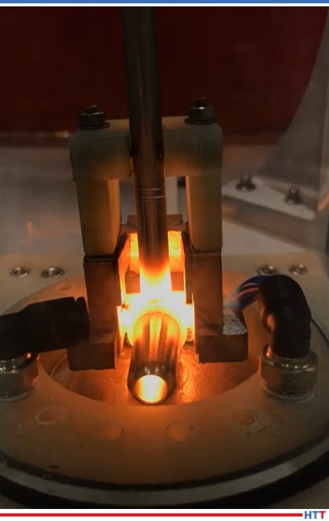
Heat Treat Radio: Fluxless inert atmosphere induction brazing. That’s a mouthful! But what is it? Watch/listen/read in full here
Heat Treat Radio host, Doug Glenn, interviews Greg Holland from eldec LLC on fluxless, inert atmosphere, induction brazing which could be a viable alternative to some flux-base furnace brazing applications.
Below, you can either listen to the podcast by clicking on the audio play button, or you can read an edited version of the transcript.
The following transcript has been edited for your reading enjoyment.
Doug Glenn (DG): We are here today with Greg Holland, a sales engineer at eldec LLC, in Auburn Hills, outside of Detroit, Michigan, and we’re going to talk today about a type of interesting induction technology. But first, tell us a little bit about you, your company, position, and how long you've been in the industry.
Greg Holland (GH): I'm a sales engineer at eldec. My main duties are inside sales, marketing activities, trade show coordinating, as well as being a coordinator and scheduler for our in-house coil shop.
Inert gas brazing: set-up Source: eldec LLC
I've been in the induction industry here for about five years now. Prior to that, I spent time in both air filtration and the thin films industry. I feel that my experiences there have really given me a wide background. It's made me a well-rounded engineer, in my humble opinion, but it's also given me a lot of perspective and some background knowledge that some of my colleagues here don't necessarily have, which has been a good thing.
eldec was established in Germany in 1982 by a gentleman named Wolfgang Schwenk. In 1998, he packed his family up and moved here to Michigan. He established what was at the time eldec Induction USA in 1998. His goal was to better cover the North American market, and what better way to cover a market like that than to be in the market? He continued to have eldec in Europe, and then he started it here in the US.
In 2001, we moved into the building we're in now, and we've been here ever since. We've grown the facility a couple of times; in 2013, eldec, as a whole, was purchased by the EMAG Group from the machine tool industry, which I'm sure a lot of your listeners are familiar with. At that time, we changed our name to eldec LLC.
DG: Greg, is there an area of specialty that eldec focuses on, or is it “all things induction”?
GH: I would say all things induction. Our office, in particular, does not do a lot of the heat treating. That is handled by our sister company here in the US, EMAG. This is mainly because if they're selling the machine tools, they are typically the customers that are then looking to heat treat. So, it makes more sense for just one person to knock on the door. I'm not saying that we aren't versed in heat treating, we definitely are. Prior to 2013, all of that was sold out of our office in North America, and we have process development capabilities that, I would say, rival what our sister company EMAG has. They are also in the Detroit area.
DG: We're going to talk about something you and I have spoken a bit about, and that is induction, fluxless, inert atmosphere. Let's start at the very basics and work our way through. What is this thing we're talking about?
GH: When you're brazing in normal air, you end up with oxides on your parts. If you don't get the oxides off of your parts, then they end up in the joint between the metal layers and the alloy. A lot of times, people will use a flux. What we are looking to do here is to eliminate the need for that flux; so, we would use an inert atmosphere.
"We are looking to try to get rid of that flux because it adds steps in your process, meaning you have to apply the flux. Then afterward, you have to clean the flux off of the part. A lot of customers aren't afraid to do that, but it's cycle time, right? You have an extra step."
DG: Basically, we're talking about brazing in an atmosphere, using induction without flux, and the primary reason is to get rid of those oxides. You kind of answered this already, but why do we need it? Why do we need that type? What's wrong with using flux?
GH: A typical braze process would use that fluxing agent, so it's either an extra paste that you would put on, or in the event that you have your brazing copper, you would have maybe a silver alloy that would have phosphorous in there. That phosphorous acts as the flux. As the alloy melts the phosphorous, it interacts with the copper oxides and basically cleans the joint for you. It also allows the alloy to wet flow and fill the joint gaps.
We are looking to try to get rid of that flux because it adds steps in your process, meaning you have to apply the flux. Then afterward, you have to clean the flux off of the part. A lot of customers aren't afraid to do that, but it's cycle time, right? You have an extra step. So, it's time, or maybe it's an extra person, whatever the case may be. By eliminating that flux, you've eliminated those steps. You don't have to worry about cleaning the part afterwards, and if you're washing the parts to get the flux off, then you don't have to figure out what to do with that wastewater.
DG: Walk us through a typical braze process that uses flux. Let me try this and you tell me if I'm good. Basically, you've got to apply the flux, and then you also have to apply some sort of a braze paste, I would assume, correct? The actual filler material?
GH: Yes. You can use a paste. What we typically use is solid alloy. If you're brazing, say in tube brazing where your joints are round, a lot of the alloy will come as a ring. You can get it specially made from a supplier as a ring, so it slides right down over your tube. If you have plates that you're brazing together, you can get a foil. It's essentially a thin sheet that you can put between the plates. You can also use a stick form, almost like a welding stick or welding rod type. Or, if you have a trough that you're trying to braze, you can get it in pellet form--little solid pieces that will go down into that trough.
DG: So, if you were doing it with flux, you would apply a flux first, then those things, and then, of course, you'd have all of the cleanup of the flux afterwards, I assume.
GH: Correct. And typically, even before you put the flux on, you want to clean the parts and make sure that you don't have dirt and dust and other types of debris in there, too.
DG: It sounds like this brazing process, where it's fluxless, is replacing a standard flux-based brazing. We've already answered the question about the significance of fluxless; basically, you're not having to use that. The other part of the description is that it's in an inert atmosphere. I would imagine that everybody knows what an inert atmosphere is, but if you don't mind, explain what is inert atmosphere and why we need it for this process.
GH: By definition, an inert gas is essentially a gas that doesn't react with anything. You're looking at helium, argon, or nitrogen. Technically, an inert atmosphere could also be a vacuum. What the goal is here, amongst some other things, is to get the oxygen out and away from the joint. By using a vacuum, you have to essentially create a chamber that is airtight. Because, as you pull a vacuum, if it's not airtight, the oxygen in the normal atmosphere is going to be seeping into that chamber.
The advantage of an inert gas atmosphere is, by filling the chamber with a nitrogen or an argon, you essentially create a higher pressure in the chamber than you do in normal atmosphere, and so you don't have to be airtight. In all actuality, you don't want to be airtight because you want to be able to purge that space and allow the air that is in there to flow out.
DG: So, you're back filling. And, by the way, for those listening, we will put a link on the transcript of this podcast, to the video that you sent that actually shows that process. It's hard to see on radio!
GH: That's actually a process that we have as part of our trade show display. At various trade shows we'll have different displays, and that one in particular, is stainless steel brazing in an inert atmosphere.
Inert gas brazing: at braze temperature Source: eldec LLC
DG: I'll describe it here just for a bit. Basically, there is a cylinder and they've got two parts inside that need to be brazed together. The cylinder, let's say it's a foot in diameter and maybe 16 or so inches tall, is a clear glass cylinder that comes down over the parts. I assume that you back fill with an argon or a nitrogen, and flush all of the oxygen out, and then it goes through a certain heating cycle and certain different KW and whatnot, and then cools at the end. Then, the lid lifts and you're off and running. That's basically how it looks
DG: Describe to us, if you don't mind, some of the industries that would use this process. What are the applications here?
GH: What we see is more so with stainless steel tube brazing, like fluid lines, automotive fuel lines, and that kind of a thing, where the end product doesn't get painted. It could be in an area that is visible to people, though, so they want it to look aesthetically pleasing. Those are the industries and processes where this gets used, but, ultimately, it can be used in any brazing application where you're currently using flux and don't want to have that additional step.
DG: You mentioned the automotive industry. Are there any other industries that you've seen it used in?
GH: We've had some other customers with essentially fittings on the end of a tube type of an application. I don't know what type of industries they ended up putting those into, but things like that are typically where we see these. But, again, it can be anything where you're heating, and honestly, it doesn't even have to be just brazing. If you have to heat something like that, you don't want to have the oxide layers and the discoloration. If you are back filling and purging that chamber with the inert gas, then as the part cools, and you allow it to cool in that inert atmosphere below the oxidation temperature, then you end up with a part that essentially doesn't even look like it was heated.
DG: Could this inert, fluxless, induction brazing potentially replace belt furnace brazing? Perhaps in some batch processes or torch brazing? Are there any savings in the process as far as manpower? I'm assuming you've still got to have somebody loading up the fixture to be brazed, right?
GH: Sure. You still have to have the fixture loaded. Depending on how the cell is laid out, it could be loaded manually, and it could be loaded by robot. You have some manpower requirements there. Typically, the actual loading isn't that much different than what you would have to do to load those parts into a fixture going through a belt furnace or to load them into a fixture heating them with a torch.
The advantage of induction over those two is not necessarily capital investment, but operating costs in the long run. You don't have the high cost of your gas. Typically, induction is more efficient than a furnace. It is a lot more efficient than a torch. You've got a guy out there with a torch that is heating your part, and then all of a sudden, he takes the torch and points it away as he does something else. All the while, the is gas burning, doing nothing. Again, with the furnace, whether you have a part flowing through there or not, you're heating that furnace and keeping it hot.
DG: Exactly. Whereas with induction, you're applying the heat and being done with it. Describe in a little bit more detail the actual process for an inert brazing process, fluxless.
GH: The chamber that you saw in the video is a large glass cylinder. They're not typically built like that. That one is built so that you can show it off and allow people to see what's actually going on. A lot of times, the chambers are much smaller. The goal is to make the space that you have to purge as small as possible, but still contain all areas of the part where the heat is going, because all of the space in that chamber has to be purged. That's an expense, so you want to limit that.
Now, depending on how long that purge cycle takes, how large your parts are, how long it takes to get to the temperature where oxidation starts to occur, you can start heating before the purge cycle is even done as long as you make sure that by the time you hit that oxidation temperature, all of the oxygen is gone. Then, you heat your part up to whatever temperature you need for your specific process.
Inert gas shield braze process where the customer wanted to eliminate oxidation in the joint area but was not concerned with oxidation of any other area of the part. As you can see in Figure A, the braze area and pipe coupling are inside of an inert gas shield and are not oxidized, whereas the housing is clearly oxidized (Figure B) as the braze cycle finishes. Source: eldec LLC
In brazing, it depends on what type of alloy is being used and what your base metals are. And then, depending on how the coil design had to be designed for your process in your part shape, you might have to allow some additional soak time. Say you are putting a really weird-shaped fitting on the end of a part; you might not be able to get a full surround coil over the tube that's going into that fitting and realistically get that back out of the assembly. You might have a coil that only goes around 120 or 180 degrees, so to allow the heat to transfer around to the rest of that joint and come to a uniform temperature for the alloy to flow, a lot of times you have a little bit of a soak time. Which is what you see in that video, as well. After the soak time, the operator can typically see through a little window; or with our power supplies, we create a recipe with a set temperature, set power, whatever the case may be if you're using a pyrometer or not, and a specified length of time, and through a little bit of process development in the very beginning, we can create that recipe. So, from a push of a button, the operator doesn't even have to see, necessarily, whether the alloy is flowing or not.
We know for development you need this much power at this much time, maybe you need two or three steps at different powers and different times, and then, all of a sudden, you know that you're going to have a good joint, you shut the power off and allow the part to cool again in that inert atmosphere. If you're not worried about aesthetics, maybe you have a part that's going to get painted and the oxides are going to affect the adhesion of that paint, or you know that you're going to have to bead blast the part anyway, maybe you're not worried about it cooling in the atmosphere, in which case you don't have that cooling step, you can just open the chamber (but be careful because then you just have a hot part). You could essentially just open the chamber and pull that part out.
DG: Would you have to do it all in an inert atmosphere, if that were the case? If you weren't worried about the oxides, you could almost do it without, at all, right?
"What we typically see there, is we're up against a furnace brace and it boils down to not only capital investment, but operating costs in the long run, what the part volumes are."
GH: If you're just heating the part. But if you're looking to braze the part, you still either have to use the flux or the inert atmosphere to keep the oxide out of the joint area.
DG: It went through the cooling process, so now it's done.
GH: Yes, that's basically the process. Then, your chamber would open once the parts cool and your operator or your robot could unload the part and load the next one. Because of the purge and cool down time, a lot of customers will end up with a unit, a power supply, that has multiple outputs on it.
For example, we’ve built a unit with three outputs for a customer multiple times. So, in that particular case, there’s a part that has two or three different braze joint locations on it. However, what you are essentially looking at is the operator. Even if it's the exact same part in all three cases, the operator can load the part in one location, allow it to start purging, and then he can load the part in the next location. When the purge cycle is over, you can have that heat time automatically start with a self-controller.
So, the operator is literally just loading station after station, and when the first one is done, the second one is loaded, purged, and ready to heat; then the third one, and off you go. By the time the operator comes back to the first one, the part is cool, the chamber opens, and he takes it out.
Essentially, you just have an operator that is loading and unloading parts and you've saved all that cycle time by having a machine that is incrementally more capital investment but saves you so much in cycle time and process flow.
DG: Right. So, you're using that cooling time or soak time to do another function which keeps your production up. Can you tell us, without naming companies, any specific examples of where this was implemented and specifically what processes it might have replaced?
GH: The one that had the three outputs that I just talked about was for automotive fuel lines. Again, I can't say the customer’s name, and I can't say which OEM the parts actually went into, but I can tell you that it was automotive fuel lines. What we typically see there, is we're up against a furnace brace and it boils down to not only capital investment, but operating costs in the long run, what the part volumes are. If it's a car model that they don't sell a lot, then they may not be able to justify the capital cost of the induction, but if you're running typical automotive volumes, then the induction portion, split over however many hundreds of thousands of parts a year, is peanuts in the end.
DG: Do you have a sense of what the cost savings was per part or anything of that sort on that example you gave?
GH: Unfortunately, I don't. A lot of our customers don't share that kind of information.
DG: Wouldn't it be nice if they told you, because it would be a great selling point to be able to say, “Hey listen, they were furnace brazing these that cost them so much per part, now they're inert fluxless brazing with induction and it cost X minus whatever per part.” That would be a great marketing thing.
DG: I guess it's probably worth mentioning here that eldec does all different types of induction, not just inert, atmosphere, fluxless brazing, right? You're doing all kinds of different types of stuff. We were just focusing in on that specific process.
If people want to get in touch with you, Greg, or just to check out eldec, where do they want to go?
GH: We can be reached through our website. eldec actually has two different websites. We have a website that is essentially a worldwide website. I think there's eight different languages on it that you can choose from. That is www.eldec.net. On that website you'll see a lot of product lines and applications.
But here, specifically in North America, we have developed a site called www.inductionheatingexperts.com. That site is more tailored to our market here in North America. On that site, you won't necessarily see as much of the heat treating, because as I mentioned earlier, our sister company EMAG handles that. If you're interested in that, their website is www.emag.com. Here in our office, our main phone number is 248-364-4750 and our general email address is info@eldec-usa.com. Me personally, you can reach me at my desk at 248-630-7756 and my email address is gholland@emag.com.
DG: I did have one other question and that is what other resources are offered by eldec?
eldec’s new online app, the Coil Design Assistant Source: www.inductionheatingexperts.com
GH: I mentioned our websites. Both websites will show a list of our products. There is at least one product line that is on the North America site that is not on the other site, and that's one that we developed and specifically developed here in North America. That's called our MiniMICO .
But also on our North American site is a tool that we've developed this year called the Coil Design Assistant. That's our CDA. I believe you guys did a little feature on it not that long ago, but that is a feature where customers can go on our website and essentially find a variety of different coil types and they can put in what dimensions they think they want or need and then we get an email and we can essentially do an approval drawing and a quote for them right there off of the web.
DG: Basically, it's a web tool to help you design a coil.
Doug Glenn, Heat Treat Todaypublisher and Heat Treat Radio host.


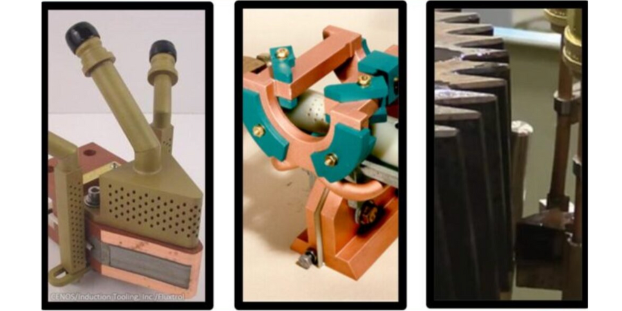
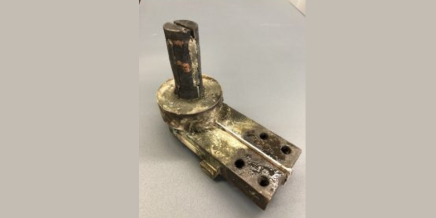

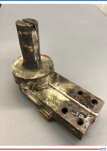

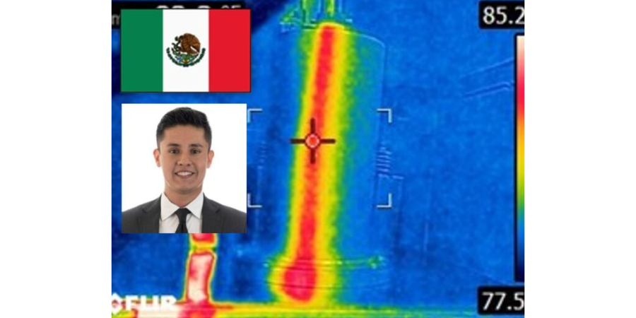


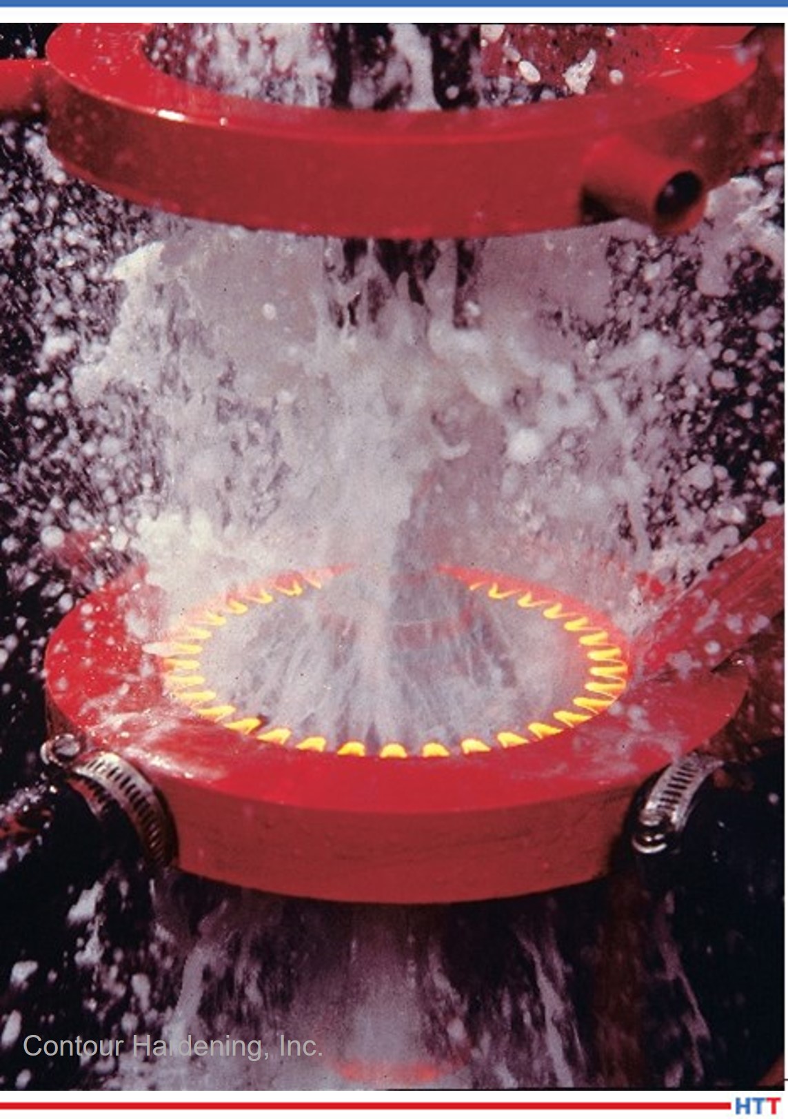
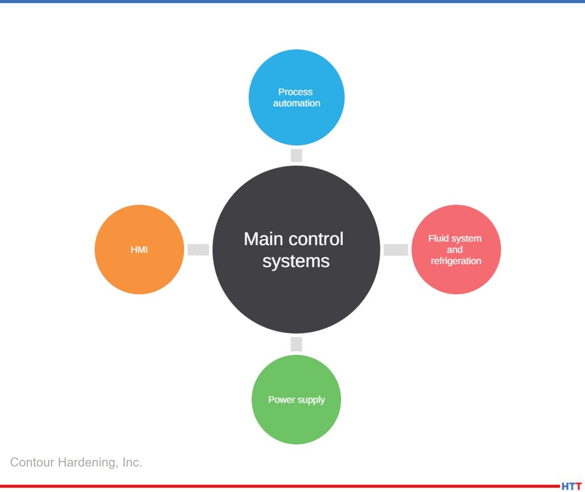
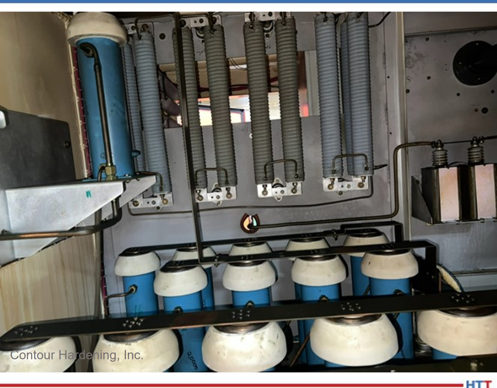
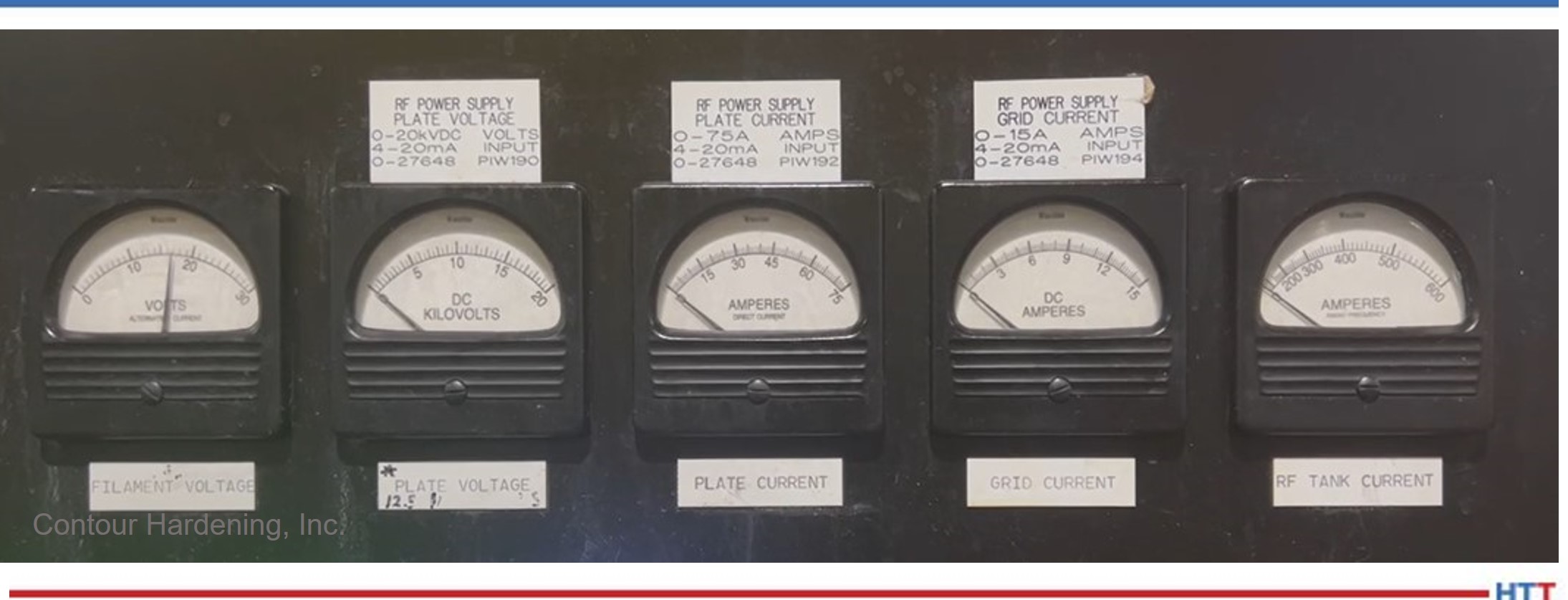
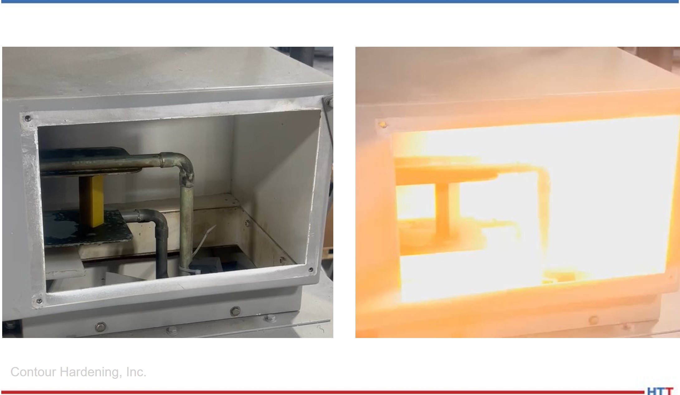
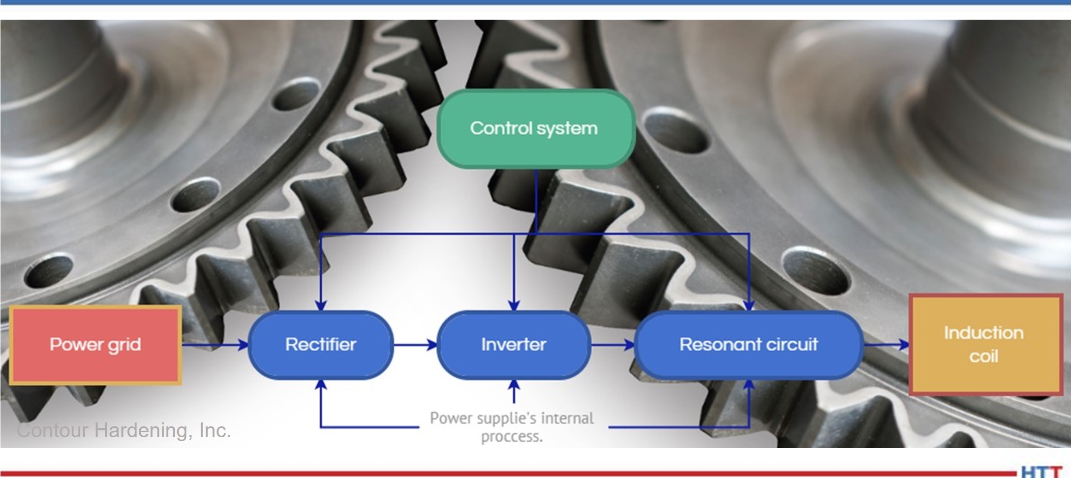
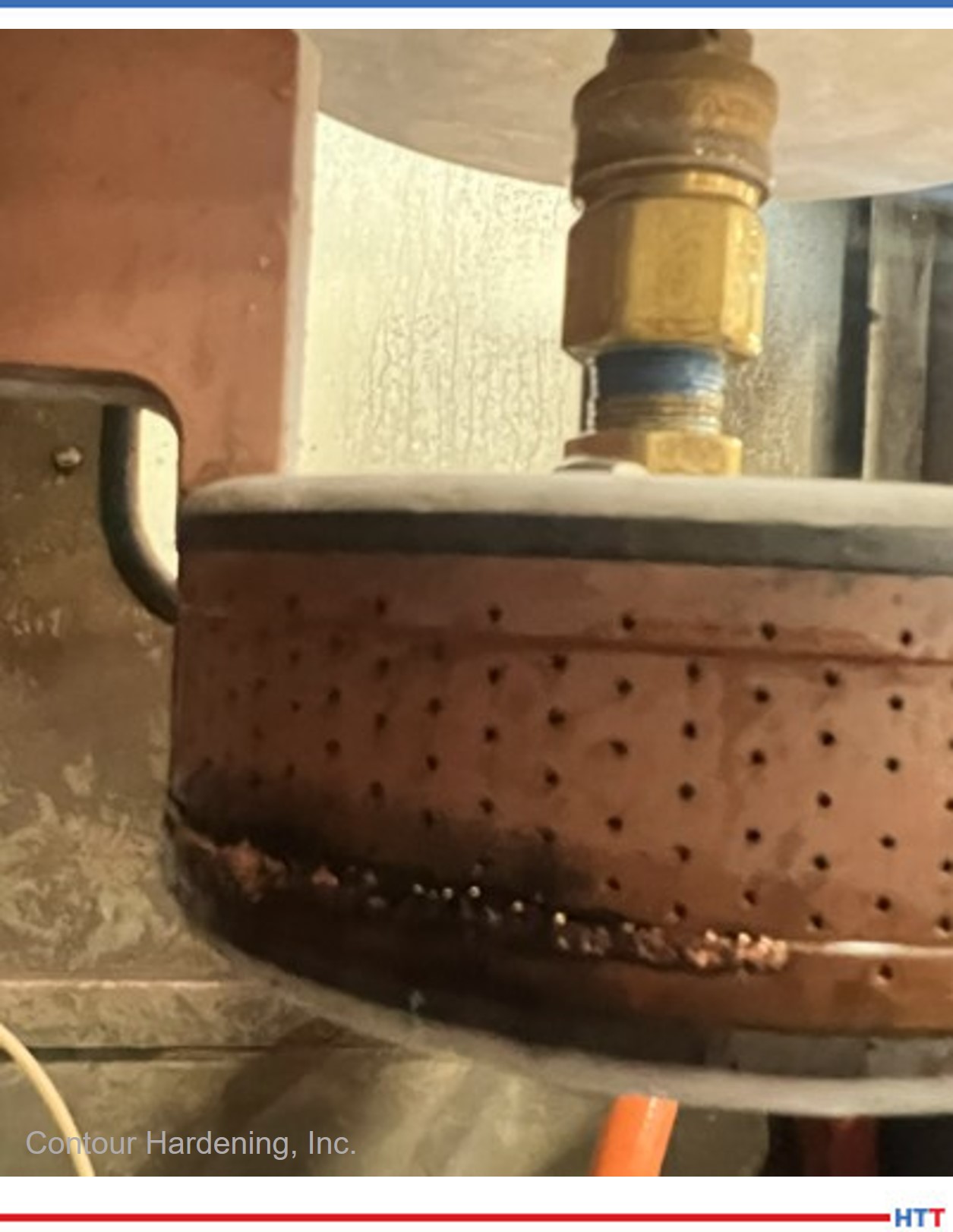
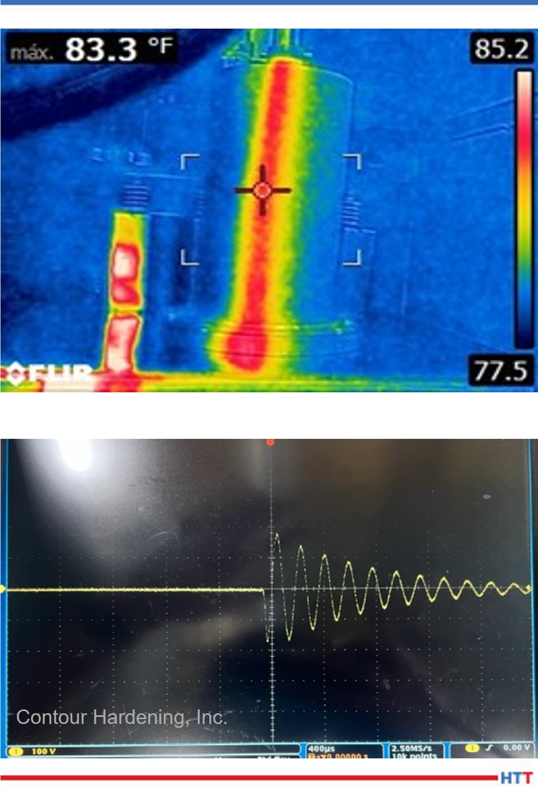


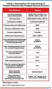
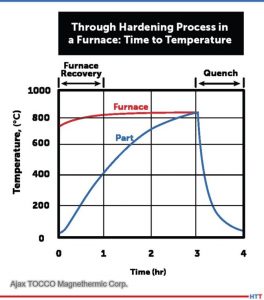
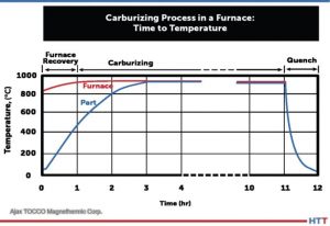
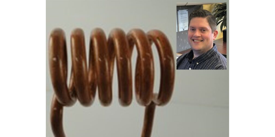

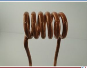
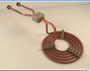
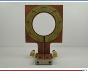


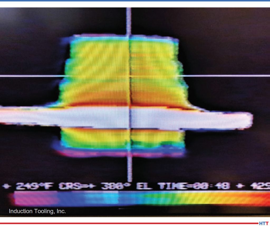
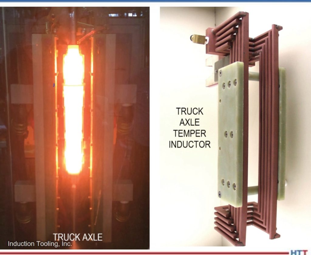

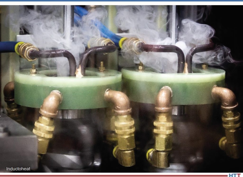
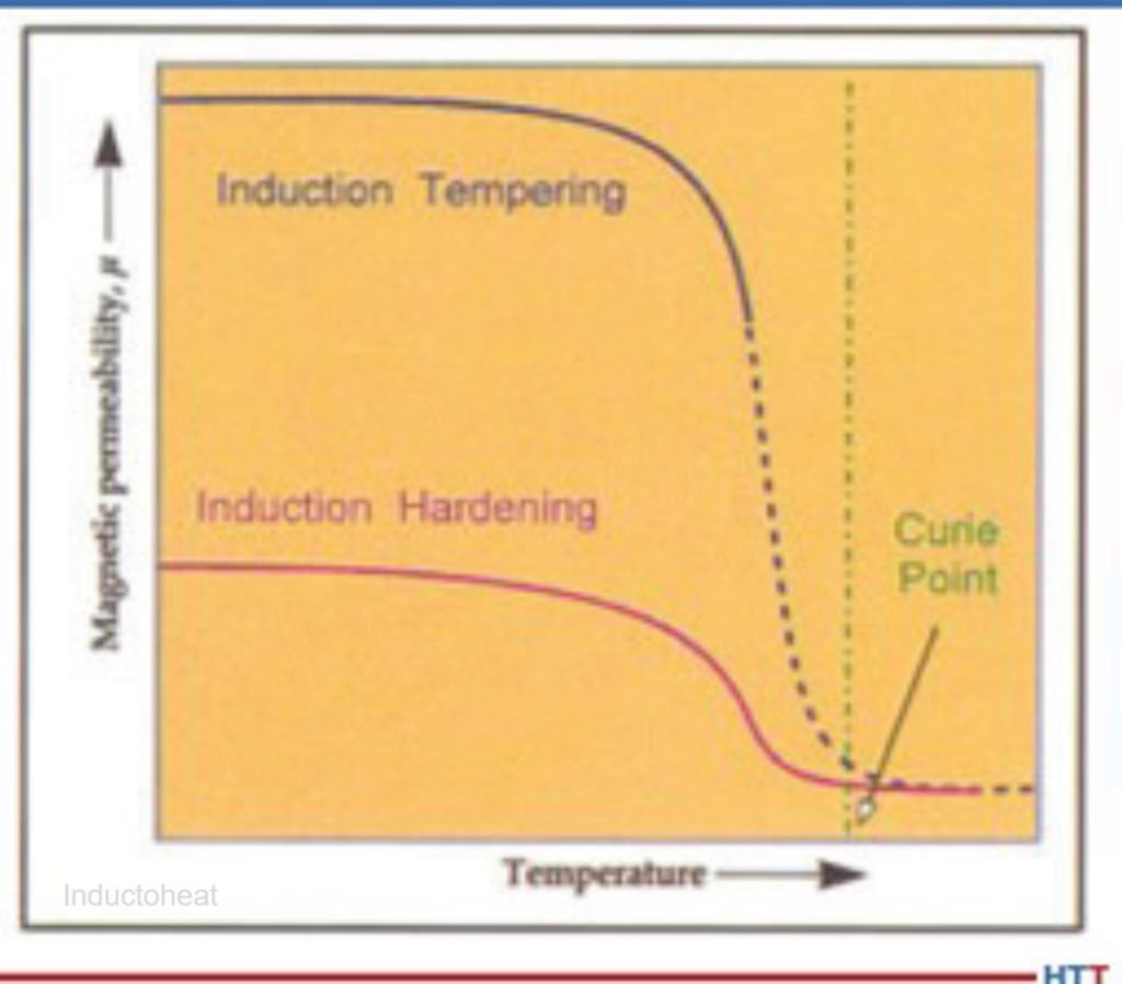


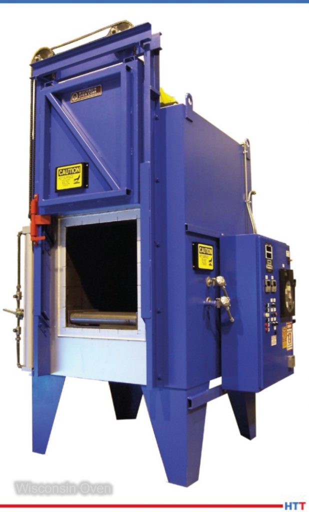
 Rapid Air Tempering
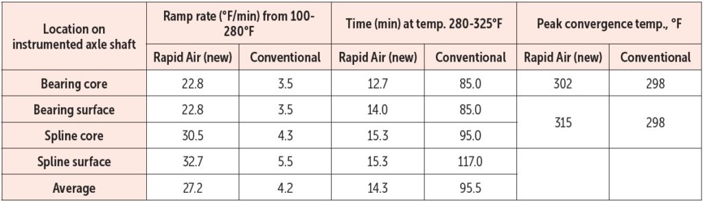
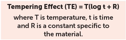
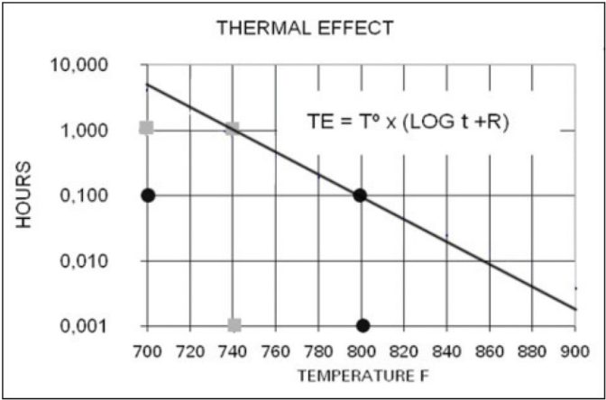


 Heat Treat