For in-house heat treat operations, the number one goal is to produce a reliable product with consistent in-service performance. Yet supply chain and specialized processes can cause consistency stressors. In this article, Heat TreatToday underlines the importance of consistent feedstock for in-house induction heat treater, National Steel Rule, and how the essential mill process of controlled decarburization can be actualized.
This informative piece was first released in Heat Treat Today’sApril 2026 Annual Induction Heating & Melting print edition.
National Steel Rule manufactures rotary cutting rule for the corrugated box industry. Located in Linden, New Jersey, the company supplies products to the die making and die cutting industries globally. They have established a high standard of sourcing, researching, and testing material for their rule, in addition to a complete testing laboratory with both rotary and flat die cutting equipment.
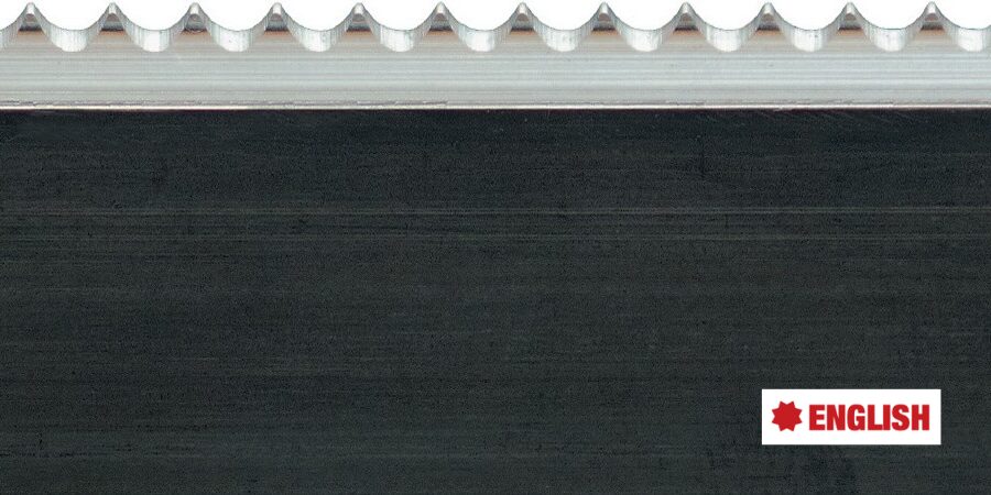
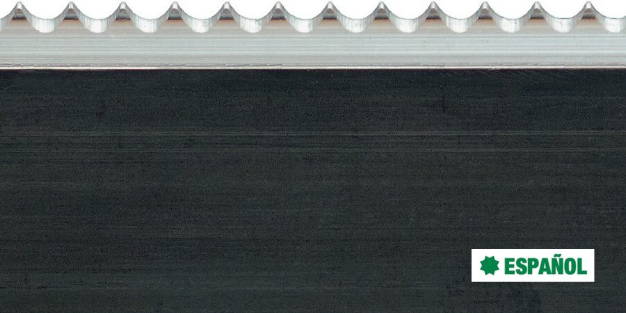
Their steel rule is purchased from a mill that performs a controlled decarburization on the entire feedstock. When National receives the steel feedstock, they work the steel to create teeth, employing induction hardening as part of the process. The finished cutting rule is then sold to steel rule die makers who mount these blades and an ejection rubber on laser cut wooden boards. The manufacturer must ensure their rule blades are sound, as even microscopic cracks will open during the die cutting process.
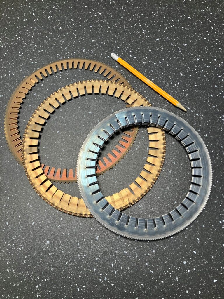
Figure 1. Small diameter bent rule | Image Credit: National Steel Rule
National’s rotary blades and other products rely on purchasing decarburized steel. “Flexibility and formability are paramount,” states Ed Mucci, president of the company, and Alexander Heucke, chief engineer. Cutting rule must be bent to form a circular blade; in service, that blade rotates to cut into the corrugated material. The curve geometry can be extreme, often bending up to a 7-inch interior diameter. As such, the purchase of decarburized steel is critical for the manufacturer’s business. At present, National sources the material internationally. Mucci explains, “Manufacturers aren’t using large quantities of decarburized steel, making it challenging to source, at least domestically.”
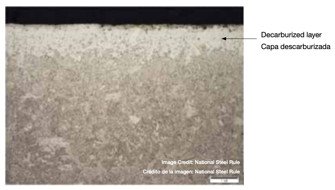
Rotary rule feedstock typically involves C36 (SAE 1036) to C50 (SAE 1050) carbon steel with a hardness range of 32–34 HRC. Mucci and Heucke note that their steel of choice has a total decarburization layer to a depth of 0.0005” depth, with partial decarburization of at least another 0.0005–0.00075”. This ensures that when the rule is bent, the surface stretches versus cracks. Bending the rule is itself a test of whether it has been properly decarburized, with metallurgical testing serving as a quality control verification that suppliers are producing the appropriate decarburization levels.
Precise Induction Hardening Teeth
While bending is essential to forming the appropriate curve, the teeth must be resistant to wear and breakage. National’s rotary cutting rule has performance expectations of at least 750,000 impressions on paper, itself a highly abrasive material. To do this, their in-house heat treat operations induction harden the edge of the rule to ensure a long die life.
There are two methods used to harden the teeth. The primary method is to shave a profile into the strip steel and then induction harden this edge. Serrated teeth are then ground in. “This gives us better control of hardening depth,” according to Mucci and Heuke. The second method is to induction harden after the serrated teeth are ground in. “We have to make sure we don’t harden the teeth too deeply, or we can affect the bendability.”
Induction hardening involves short cycles, and as such requires careful process control to guarantee consistent results; temperature-indicating crayons that melt at a specific temperature are used as one of the process control methods. Hardness testing is performed as well.
Screenshot
Decarburization Revisited
“Usually, one tries to prevent decarburization or even add carbon,” states Mark Hemsath, executive consultant at WINGENS CONSULTANTS and longtime expert and innovator in the thermal processing industry. “Decarb often occurs by accident in poorly designed annealing systems, especially in continuous-type furnaces.”
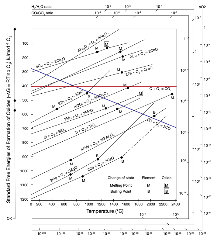
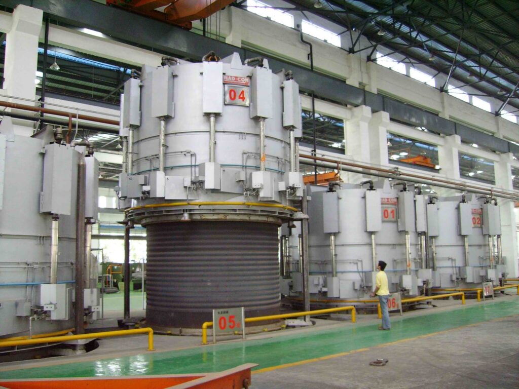
Figure 3. Ellingham Diagram depicting that hydrogen-to-water vapor relationship, the key to a successful, controlled decarburization.Figure 4. Typical bell-annealing furnace | Image Credit: RAD-CON
Oxygen, in the form of air or water vapor, is key to the decarburizing process. Less carbon on the surface means a softer, more malleable steel, and while the art of a controlled decarburization process is well known, it can be challenging. Decarburization is a process usually performed below 1500°F. “The preferred method is to use water vapor or steam as a source of the oxygen,” notes Hemsath, pointing to the stability of hydrogen-to-water vapor (H₂/H₂O ratio) derived from the Ellingham diagram. These H₂/H₂O ratios indicate the non-oxidizing qualities of the gaseous mixture, which will allow it to be the carbon reducing agent in the atmosphere. Most furnace companies can provide the necessary equipment and customize size specifications to make it suitable for this special process, and these furnaces are typically retort-based bell or pit type.
Two Methods to Control the Decarb
There are two ways that a decarburization process can be intentionally completed. The first is decarburizing the entire product. In this method, even decarburization is applied to the entire coil sheet surface. “This cold rolled steel, typically with lower carbon, is used for appliances that need enamel adhesion,” Hemsath explained, noting U.S. Steel and AK Steel, now a part of Cleveland-Cliffs, have used this form of controlled decarburization.
Another form of decarburization is selective surface decarburization. Hemsath shared, “If selective decarburizing is required only on the edges, then you could keep the coils tightly wound and the decarburization would affect mainly the coil edges. There would be ingress of carbon loss, reducing towards the center of the wound coil surfaces.”
Conclusion
“Decarburized steel just isn’t in high demand,” according to Mucci, as “most industries are looking to harden and temper the steels they use.” In fact, preventative steel decarburization is more typical and often emphasized in trade shows, technical presentations, and in thermal processing publications. Yet there are products that rely on intentional decarburization to be successful.
Controlled decarburization at the mill brings challenges, in part because successful, consistent decarburization is not often cost effective for the North American thermal processing market. These challenges encompass regional access issues, niche market access, equipment selection needs, and technical process execution.
National’s experience underlines the challenges North American mills face in providing local, in-house heat treaters with reliably, well-controlled decarburized steel that will maintain service life.
Acknowledgements: Heat TreatTodayextends thanks to Dan Herring, The Heat Treat Doctor® at The HERRING GROUP, Inc., who was instrumental in the development of this article.
Para las operaciones de tratamiento térmico internas (in house), el objetivo principal es producir un producto confiable con un desempeño consistente en servicio. Sin embargo, la cadena de suministro y los procesos especializados pueden generar factores que comprometen la consistencia. En este artículo, Heat TreatTodaydestaca la importancia de contar con material base consistente para el tratamiento térmico por inducción interno de National Steel Rule, y cómo se puede implementar el proceso esencial de descarburización controlada en la planta proveedora de acero.
Este artículo informativo se publicó por primera vez enHeat Treat Today’sApril 2026 Annual Induction Heating & Melting print edition. Traducido por Ana Laura Hernández Sustaita.
La empresa National Steel Rule produce reglas de corte rotativas para la industria del cartón corrugado. Ubicada en Linden, Nueva Jersey, la empresa suministra productos a las industrias de troquelado a nivel mundial. La compañía ha establecido altos estándares de abastecimiento, investigación y pruebas de material para sus reglas de corte, además de contar con un completo laboratorio con equipos de troquelado rotativo y plano.
Su regla de acero se adquiere de una planta proveedora de acero que realiza una descarburización controlada en todo el material. Cuando National recibe el material, procesa el acero para generar los dientes, empleando endurecimiento por inducción como parte del proceso (ver la imagen principal al inicio de este artículo). La regla de corte terminada se vende posteriormente a fabricantes de troqueles de regla de acero, quienes montan estas cuchillas junto con una goma de expulsión sobre tableros de madera cortados con láser. El fabricante debe asegurarse de que las cuchillas de las reglas estén libres de defectos, ya que incluso grietas microscópicas se abrirán durante el troquelado.
Figura 1. Regla de acero doblada de diámetro pequeño | Crédito de la imagen: National Steel Rule
Las cuchillas rotativas y otros productos de National dependen de la compra de acero descarburizado. “La flexibilidad y la conformabilidad son fundamentales”, afirma Ed Mucci, presidente de la empresa, y Alexander Heucke, ingeniero en jefe. La regla de corte debe doblarse para formar una cuchilla circular; durante el servicio, la cuchilla rota para cortar el material corrugado. La geometría de la curvatura puede ser extrema, llegando a doblarse hasta un diámetro interior de 7 pulgadas. Por lo tanto, la compra de acero descarburizado es crítica para el negocio del fabricante. Actualmente, National obtiene el material a nivel internacional. Mucci explica: “Los fabricantes no utilizan grandes cantidades de acero descarburizado, lo que dificulta su abastecimiento, al menos a nivel nacional”.
El material para las reglas rotativas suele ser acero al carbono C36 (SAE 1036) a C50 (SAE 1050) con un rango de dureza de 32–34 HRC. Mucci y Heucke señalan que el acero que utilizan presenta una capa de descarburización total de 0.0005” de profundidad, con una descarburización parcial adicional de al menos 0.0005”–0.00075”. Esto garantiza que cuando una regla se dobla, la superficie se elongue en lugar de agrietarse. Doblar la regla es, en sí mismo, una prueba para comprobar si se ha descarburado correctamente, y las pruebas metalúrgicas sirven como verificación de control de calidad para garantizar que los proveedores estén produciendo los niveles adecuados de descarburización.
Endurecimiento Preciso por Inducción de los Dientes
Si bien el doblado es esencial para formar la curvatura apropiada, los dientes deben ser resistentes al desgaste y la rotura. La regla de corte rotativa de National tiene una expectativa de desempeño de al menos 750,000 impresiones en papel, que es en sí mismo un material altamente abrasivo. Para lograrlo, las operaciones de tratamiento térmico internas endurecen por inducción el borde de la regla, garantizando una larga vida útil del troquel.
Existen dos métodos usados para endurecer los dientes. El método principal es maquinar el perfil de la tira de acero y posteriormente endurecer por inducción el borde. Posteriormente los dientes son rectificados. “Esto nos da un mejor control sobre la profundidad de endurecimiento”, comenta Mucci y Heuke. El segundo método consiste en endurecer por inducción después de rectificar los dientes. “Debemos asegurarnos de que el endurecimiento de los dientes no sea muy profundo, ya que esto puede afectar la capacidad de doblado”. El endurecimiento por inducción implica ciclos muy cortos, y por lo tanto requiere un control minucioso del proceso para garantizar resultados consistentes. Entre los métodos de control del proceso se utilizan crayones indicadores de temperatura, que se funden a una temperatura específica. También se realizan pruebas de dureza.
Figura 2. Detalle de la capa descarburizada | Crédito de la imagen: National Steel Rule
Revisitando la Descarburización
“Generalmente se intenta prevenir la descarburización o incluso agregar carbono a la superficie”, comenta Mark Hemsath, consultor ejecutivo en WINGENS CONSULTANTS y reconocido experto e innovador en la industria del tratamiento térmico. “La descarburización a menudo ocurre accidentalmente en sistemas de recocido mal diseñados, especialmente en hornos de tratamiento continuo.”
Figura 3. Diagrama de Ellingham que muestra la relación hidrógeno-vapor de agua, clave para una descarburización controlada exitosa. Figura 4. Horno típico de recocido tipo campana. | Crédito de la imagen: RAD-CON
El oxígeno en forma de aire o de vapor es la clave del proceso de descarburización. Menor porcentaje de carbono en la superficie indica un acero más blando y maleable, y si bien el arte de un proceso de descarburización controlada es bien conocido, puede resultar un desafío. El proceso de descarburización suele realizarse por debajo de 1500°F (815°C). “El método preferido es usar vapor de agua o vapor como fuente de oxígeno”, señala Hemsath. Esto se basa en la estabilidad de la relación hidrógeno-vapor de agua (H2/H2O) derivada del diagrama de Ellingham. Estas relaciones H2/H2O indican las propiedades no oxidantes de la mezcla gaseosa, lo que permite que actúe como agente reductor de carbono en la atmósfera del horno. La mayoría de las empresas fabricantes de hornos pueden proporcionar el equipo necesario y personalizar las dimensiones para hacerlos adecuados para este proceso especial. Estos hornos suelen ser de tipo campana o tipo foso con retorta.
Dos Métodos para Controlar la Descarburización
Existen dos formas de realizar intencionalmente un proceso de descarburización. La primera consiste en descarburar todo el producto. En este método, la descarburización se aplica de manera uniforme en toda la superficie de la lámina o bobina. “Este acero laminado en frío generalmente con menor contenido de carbono, se utiliza en electrodomésticos que requieren una buena adherencia del esmalte”, explica Hemsath. Empresas como U.S. Steel y AK Steel (ahora parte de Cleveland-Cliffs) han utilizado esta forma de descarburización controlada.
Otra forma es la descarburización selectiva en la superficie. Hemsath explica: “Si la descarburización solo se requiere en los bordes, se podrían mantener las bobinas enrolladas firmemente, por lo tanto, la descarburización afectaría principalmente a los bordes. Se produciría una pérdida de carbono que disminuiría hacia el centro de las superficies enrolladas”.
Conclusión
“El acero descarburizado tiene mucha demanda, ya que la mayoría de las industrias buscan endurecer y templar los aceros que utilizan”, indica Mucci. De hecho, la prevención de la descarburización del acero es más común y suele destacar en ferias industriales, presentaciones técnicas y publicaciones de procesamiento térmico. Sin embargo, existen productos que dependen de la descarburización intencional para funcionar correctamente.
La descarburización controlada en la planta proveedora de acero presenta desafíos, en parte porque lograr una descarburización exitosa y consistente no suele ser económicamente viable para el mercado norteamericano de tratamiento térmico. Estos desafíos abarcan problemas de acceso regional, acceso a nichos de mercado, necesidades de selección de equipos y ejecución de procesos técnicos.
La experiencia de National destaca los desafíos que enfrentan las plantas proveedoras de acero de América del Norte para proveer a las empresas de tratamiento térmico interno, acero descarburizado de forma fiable y bien controlada que mantenga su vida útil.
Agradecimientos: Heat TreatToday agradece a Dan Herring, The Heat Treat Doctor®, The HERRING GROUP, Inc.,quien fue fundamental en el desarrollo de este artículo.
Ask The Heat Treat Doctor® has returned to bring sage advice to Heat Treat Today readers and to answer your questions about heat treating, brazing, sintering, and other types of thermal treatments as well as questions on metallurgy, equipment, and process-related issues. In this installment, Dan Herring continues his discussion on gear heat treatment, exploring vacuum and induction hardening methods for gears — from low-pressure carburizing for advanced materials to single shot and tooth-by-tooth induction techniques — and how each can be matched to the specific demands of any gear application.
This informative piece was first released in Heat Treat Today’sMarch 2026 Annual Aerospace Heat Treating print edition.
In Part One of this discussion (Air & Atmospheres Heat Treating, February 2026), we discussed various gear types, materials, and how they can be atmosphere heat treated. This month, we are focusing on vacuum and induction heat treating methods. Let’s learn more.
Vacuum Heat Treatment Processing Methods
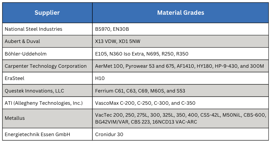
Table A. Advanced Materials Processed by LPC
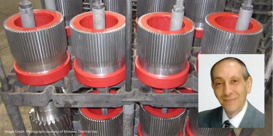
Vacuum processing can be used for most of the atmosphere treatments mentioned in Part One including carburizing (Figure 1). Low pressure carburizing (LPC) is a proven technology and the choice for many advanced applications in aerospace, automotive, off-highway, and motorsports markets, as well as the development of carburizing cycles for high-performance materials (Table A).
Figure 1. Typical commercial heat treat load of gears for vacuum carburizing (Otto and Herring 2007) | Image Credit: Photo courtesy of Midwest Thermal-VacFigure 2. Pyrowear 675 – LPC – anneal – double normalize – harden – anneal – deep freeze – double temper | Image Credit: The HERRING GROUP, Inc.
The range of effective case depths for most of these grades can range up to 2.0–3.0 mm (0.080–0.120 inches) without significant sacrifice of microstructure (Figure 2). Furnace variables, such as temperature uniformity (± 3°C or ± 5°F), control of cycle parameters (boost/diffuse times, gas flow rate, pressure, hydrocarbon type) and surface carbon optimize the microstructure, producing case uniformities of ± 0.05 mm (± 0.002 inches). Where permitted, the range of carburizing temperatures now includes the use of high temperature (> 980°C, or 1800°F) techniques.
All these advanced materials required extensive development testing to produce custom designed recipes to optimize cycle parameters. Also, quenching methods (Otto and Herring 2002) have improved, allowing us to achieve desired core properties with quenching parameter selection (high-pressure gas or oil) for distortion-sensitive and distortion-prone part geometries (Otto and Herring 2005, 2008).
Induction Hardening Methods
Various methods of hardening via applied energy are used in manufacturing gears, including flame hardening, laser surface hardening, and induction hardening.
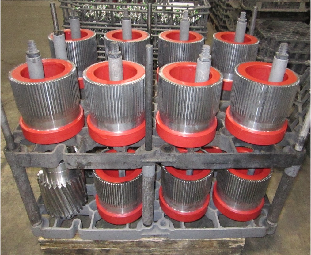
Of the various types of applied energy processing, induction hardening is the most common. Induction heating is a process that uses alternating electrical current that induces a magnetic field, causing the surface of the gear teeth to heat. The area is then quenched resulting in an increase in hardness within the heated area. This process is typically accomplished in a relatively short time. The final desired gear performance characteristics are determined not only by the hardness profile and stresses but also by the steel composition and prior microstructure. External spur and helical gears, bevel and worm gears, racks, and sprockets are commonly induction hardened. Typical gear steels include AISI/SAE grades 1050, 1060, 1144, 4140, 4150, 4350, 5150, and 8650.
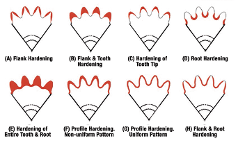
Figure 3. Patterns produced by induction hardening (Rudnev 2000)
The hardness pattern produced by induction heating (Figure 3) is a function of the type and shape of inductor used, as well as the heating method. Quenching or rapidly cooling the workpiece can be accomplished by spray or submerged quench. The media typically used for the quench is a water-based polymer. The severity of this quenchant can be controlled by the polymer’s concentration. Cooling rates are usually somewhere in between what would be obtained from pure water and oil. In some unusual situations compressed air or nitrogen is used to quench the part.
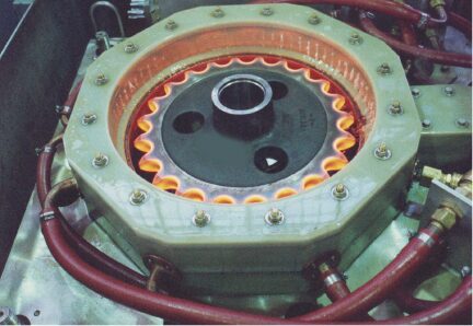
The most common methods for hardening gears and sprockets are by single shot (Figure 4) or the tooth-by-tooth method (Figure 5). Single shot often requires large kW power supplies but results in short heat/quench times and higher production rates. This technique uses a circumferential copper inductor, which will harden the teeth from the tips downward.
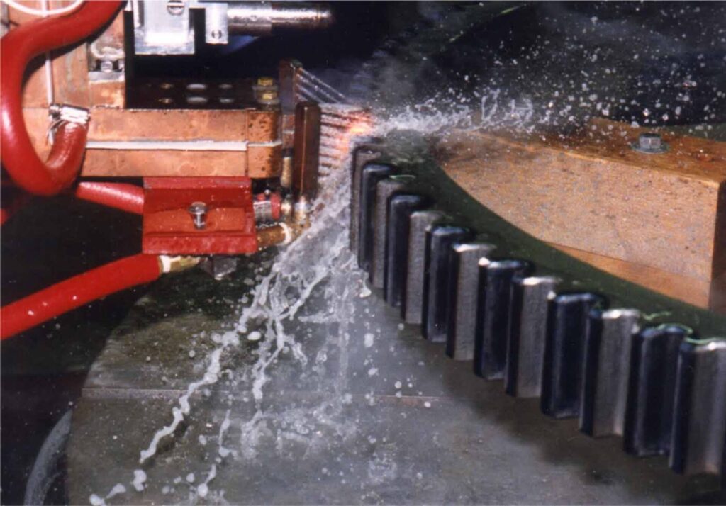
Figure 4. Typical single shot induction hardening operation | Image Credit: Photo courtesy of Ajax-Tocco-MagnethermicFigure 5. Tooth-by-tooth induction hardening of a helical gear | Image Credit: Photo courtesy of Ajax-Tocco-Magnethermic
The larger and heavier loaded gears (where pitting, spalling, tooth fatigue, and endurance are issues) need a hardness pattern that is more profiled like those produced by carburizing, which can be obtained by tooth-by-tooth hardening. This method is limited to gear tooth sizes with modulus 4.23–5.08 (6 or 5 DP) using frequencies from 2 to 10 kHz and about 2.54 (10 DP) using a range of 25 to 50 kHz.
The lower the frequency, the deeper the case depth. Tooth-by-tooth hardening is a slow process and usually reserved for gears and sprockets that are too large to single shot due to power constraints. The process involves heating the root area and side flanks simultaneously, while cooling each side of the adjacent tooth to prevent temper-back on the backside of each tooth. The induction system moves the coil at a pre-programmed rate along the length of the gear. The coil progressively heats the entire length of the gear segment while a quench follower immediately cools the previously heated area. The distance from the coil to the tooth is known as coupling or air gap. Any changes in this distance can yield variation in case depth, hardness, and tooth distortion. The gear is indexed after each tooth has been hardened, often skipping a tooth. This requires at least two full revolutions in the process to complete the hardening of all teeth. Straight, spur, and helical gears up to 5.5 m (210 inches) weighing 6,800 kg (15,000 lb) have been processed with this method. The entire process yields a repeatable soft tip of the tooth with hard root and flank. In other applications, the tip and both flanks can be hardened simultaneously and yield a soft root.
In Summary
Today’s design engineer has the good fortune of being able to choose from a number of heat treatment technologies for any given type of gear material and design. When selecting a gear hardening method, it is essential to specify not only the desired mechanical and metallurgical properties, but the critical dimensions that must be held and even the desired stress state of the gears themselves. The secret to success is understanding the advantages and limitations of each technology and taking these into consideration when determining the overall cost of gear manufacturing.
References
Herring, Daniel H. 2004a. “Gear Heat Treatment: The Influence of Materials and Geometry.” Gear Technology, March/April.
Herring, Daniel H. 2004b. “Reducing Distortion in Heat-Treated Gears.” Gear Solutions, June.
Herring, Daniel H. 2007a. “Oil Quenching Technologies for Gears.” With Steven D. Balme. Gear Solutions, July.
Herring, Daniel H. 2007b. “Heat Treating Heavy Duty Gears.” With Gerald D. Lindell. Gear Solutions, October.
Herring, Daniel H. 2012–2016. Vacuum Heat Treatment. Vols. 1–2. BNP Media Group.
Herring, Daniel H. 2014–2015. Atmosphere Heat Treatment. Vols. 1–2. BNP Media Group.
Herring, Daniel H., Gerald D. Lindell, D. J. Breuer, and B. Matlock. 2001. “Atmosphere vs. Vacuum Carburizing.” Heat Treating Progress, November.
Herring, Daniel H., Gerald D. Lindell, D. J. Breuer, and B. Matlock. 2002. “An Evaluation of Atmosphere and Vacuum Carburizing Methods for the Heat Treatment of Gears.” In Off-Highway Conference Proceedings. SAE International.
Otto, Frederick J., and Daniel H. Herring. 2002a. “Gear Heat Treatment: Today and Tomorrow, Part 1.” Heat Treating Progress, June.
Otto, Frederick J., and Daniel H. Herring. 2002b. “Gear Heat Treatment: Today and Tomorrow, Part 2.” Heat Treating Progress, July/August.
Otto, Frederick J., and Daniel H. Herring. 2005. “Vacuum Carburizing of Aerospace and Automotive Materials.” Heat Treating Progress, January/February.
Otto, Frederick J., and Daniel H. Herring. 2007. “Advancements in Precision Carburizing of Aerospace and Motorsports Materials.” Heat Treating Progress, May/June.
Otto, Frederick J., and Daniel H. Herring. 2008. “Improvements in Dimensional Control of Heat Treated Gears.” Gear Solutions, June.
Rudnev, V. 2000. “Gear Heat Treating by Induction.” Gear Technology, March/April.
About the Author
Dan Herring “The Heat Treat Doctor” The HERRING GROUP, Inc.
Dan Herring has been in the industry for over 50 years and has gained vast experience in fields that include materials science, engineering, metallurgy, new product research, and many other areas. He is the author of six books and over 700 technical articles.
As pressure mounts to cut industrial CO2 emissions, hybrid heating systems are emerging as a compelling pathway to decarbonizing industrial process heat. In this Technical Tuesday installment, Dr.-Ing. Marco Rische and Dr. Martin Ennen of ABP Induction Systems GmbH explore how integrating induction technology at the front and end of traditional gas-fired furnace heat treating can reduce energy consumption, improve temperature control, lower operating costs, and offer a realistic bridge to full electrification.
This informative piece was first released inHeat Treat Today’sJanuary 2025 Annual Technologies To Watch print edition.
The metalworking industry is undergoing a profound transformation, as the pressure to reduce emissions and replace fossil fuels continues to shape technological strategies across all areas of the value chain. In addition to melting technology, process heat is increasingly coming into focus — namely the heating, warming, and tempering of materials, which is required in virtually every production process.
With hybrid approaches that combine conventional gas furnaces with induction heating units, energy consumption, CO2 emissions, and costs can be reduced simultaneously. ABP Induction, a global provider of electric heating and melting technologies, has continued to refine and expand hybrid heating concepts over the past several years. Its strategy aims to help shape the path to CO2 neutrality as a partner to the metalworking industry through holistic solutions that balance technological advances and cost efficiency.
The Pressure to Act in the Industry
The starting point is both a challenge and an opportunity; the metalworking industry ranks among the largest industrial producers of CO2 emissions worldwide. The steel industry, in particular, is at the center of the decarbonization debate, accounting for roughly one quarter of global industrial emissions. Natural gas was the preferred fuel for many years: affordable, easy to control, and simple to transport. But with rising CO2 prices and increasing political pressure to decarbonize, the balance is shifting. While primary processes like pig iron production are increasingly shifting toward direct reduction using hydrogen, heat input in downstream processing steps, such as melting, heating, or rolling, still primarily relies on fossil energy sources.
At the same time, the economic landscape is shifting; rising CO2 prices, high energy costs, and the need for stable supply chains are driving a reassessment of conventional technologies and laying the foundation for induction-based burner substitutes to gain economic traction. The megatrends of digitalization, deglobalization, demographic change, and decarbonization are now shaping business decisions across the metalworking industry. After all, the energy policy framework is creating incentives to deploy electric solutions, especially where they can be powered by green electricity. This makes induction — contactless heating of metallic materials using electromagnetic fields — a key technology on the path to CO2 neutrality.
Induction Heating as a Foundational Technology
The physical principle of induction is well established. An alternating electromagnetic field transfers energy directly into the workpiece, heating it evenly and in a controlled manner. The advantages lie in high energy efficiency, dynamic controllability, and reliable process stability. While gas burners rely on convective and radiant heat, induction applies energy directly without intermediate losses — a decisive efficiency advantage that enables practical efficiencies of up to 90%.
For many applications, the technology is already widely adopted. In foundries, induction furnaces are increasingly replacing cupola furnace systems, while in forges and aluminum plants, induction systems are used for efficient preheating and heating. New application areas are emerging in the steel sector, particularly in the fields of reheating and heat treatment.
However, the limitations are equally clear; induction works optimally only where the material to be heated is electrically conductive and the electromagnetic field can be efficiently coupled. For large-volume or indirect heating processes, such as those involving gas flows or non-metallic materials, complementary concepts are required.
The Principle of Hybrid Heating
This is precisely where hybrid heating systems come into play. They combine proven induction technology with conventional furnace systems, typically gas-fired continuous or chamber furnaces. The goal is to leverage the strengths of both systems and compensate for their weaknesses.
A typical hybrid system integrates an induction section before or after the gas-fired furnace. When the induction unit is positioned upstream, it handles the rapid heating phase, bringing the workpiece to a defined temperature in a short time, which effectively reduces the load on the gas-fired furnace. It can then operate with reduced energy input. When the induction unit is positioned downstream, it ensures precise temperature control, homogenizes the temperature profile, or compensates for fluctuations in transport speed.
The benefits are multifaceted: gas consumption decreases, temperature distribution becomes more uniform, production speed can increase, and CO2 emissions are significantly reduced. Pilot projects have achieved savings of up to 60% in previous fossil energy consumption.
In addition, the hybrid solution enables a gradual transformation process. Existing furnace systems can continue to be used, keeping investments in new infrastructure to a minimum. This provides operators with an economically and technically viable path to decarbonization and allows them to stay close to the existing process without compromising production reliability.
Process Integration and Control
Hybrid heating systems are highly adaptable. The design of the induction section depends on material, geometry, throughput, and process objective. Modern control technology ensures precise coordination between induction and furnace operation.
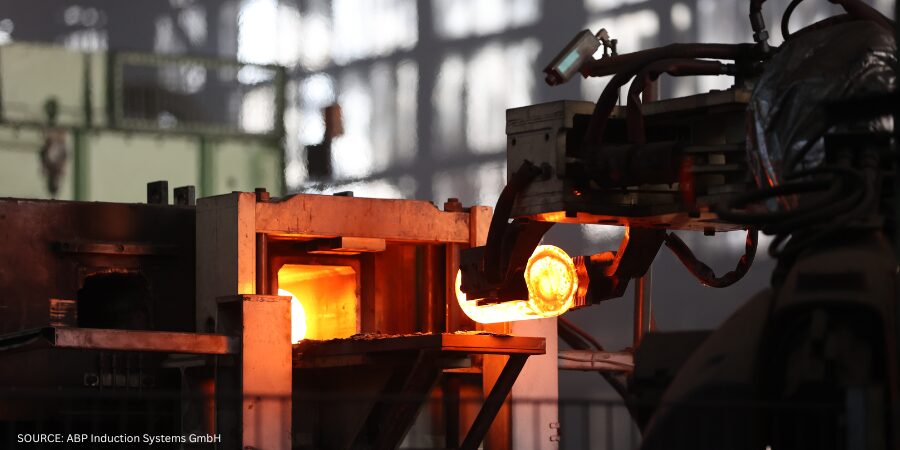
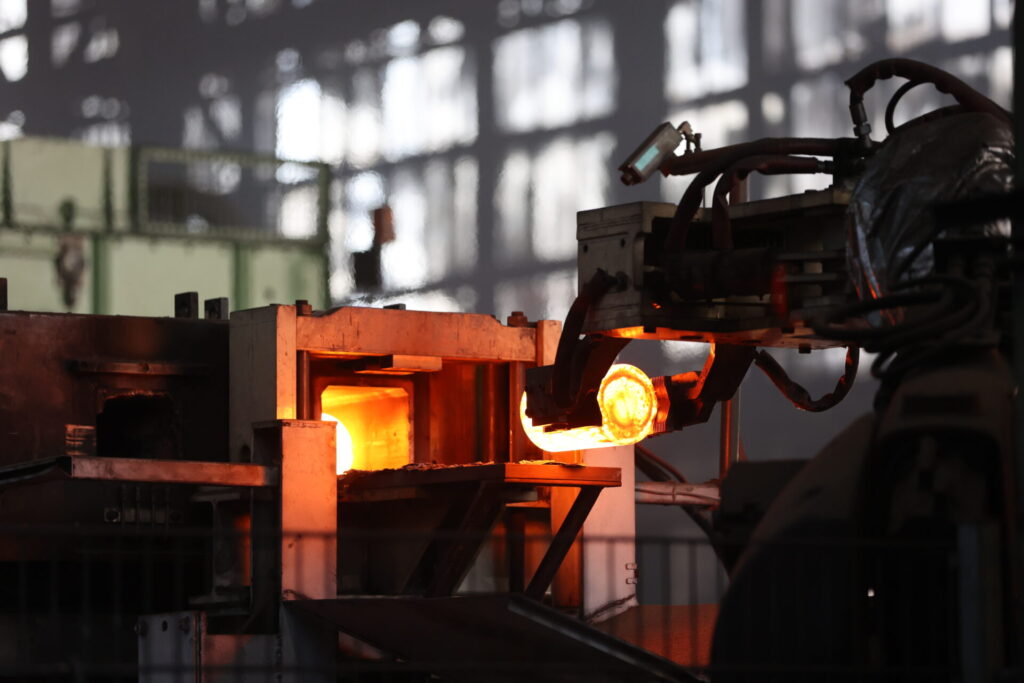
Figure 1. Billet after induction heating process | Source: ABP Induction Systems GmbH
In the area of reheating slabs or billets in rolling mills, for example, an inductive preheating station can be installed in front of the furnace. Here, the induced power density is utilized to significantly shorten the heating time. At production rates of up to 200 tons per hour for long products and 1,000 tons per hour for flat products, induction systems achieve electrical efficiencies of 85% to 90%. Downstream of the furnace, a post-heating unit can help maintain a uniform temperature profile, a critical factor for product quality, dimensional accuracy, and potentially reduced wear on subsequent forming equipment. Process stability also benefits. Gas-fired furnaces are sluggish systems whose temperature responds slowly to process changes. Induction systems, on the other hand, can be controlled within fractions of a second, adding a dynamic component to the overall system. This allows temperature fluctuations to be compensated, which helps to prevent product defects.
A Tool for Transformation
The idea of replacing fossil fuel burners with induction systems is not new. Pioneers in the field considered this decades ago and developed alternative processes and methods, but it was never cost-effective. Fossil fuel usage remained cheaper and allowed existing processes to continue unchanged. Now the situation is different.
Figure 2. UHT Thermo Jet UHT200® — Induction heating concepts for fluids | Image Credit: TUBAF University of Freiberg
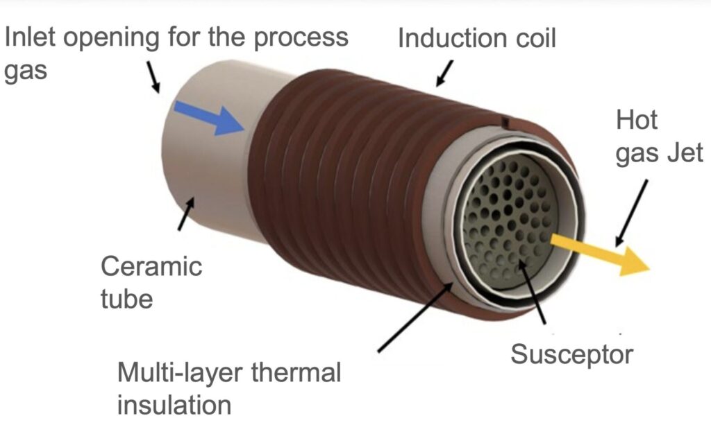
A key element in ABP Induction’s strategy for electrifying process heat is the Ultra-High-Temperature (UHT) Thermo Jet, a newly developed high-temperature hot gas technology that replaces conventional fossil fuel burners and electrifies industrial thermal processes. The innovation marks a decisive step toward fully electric process heat, demonstrating that even high-temperature applications are feasible without the combustion of fossil fuels.
The system is based on an inductively heated metallic susceptor located inside a high-temperature-resistant, thermally insulated channel. A process gas flows through it, typically air, though inert gases or exhaust gases can also be used. The induction coil generates an electromagnetic field (Figure 2) that heats the susceptor without physical contact. The susceptor then transfers the heat to the gas flowing past it. The result is a hot gas jet with temperatures well above 1000°C (1830°F), fully replicating the thermal characteristics of a natural gas flame. Industrial test series have already achieved stable temperatures of up to 1400°C (2550°F) with response dynamics that surpasses conventional burners.
The technology transfers energy in two stages: first, the susceptor is heated via induction; then, the heat is transferred to the gas stream. This decoupled structure enables precise control of temperature, gas flow, and power input. The key lies in synchronizing the electrical power control with the gas flow to ensure a consistent and reproducible hot gas quality. The system responds to load changes within seconds, offering a level of controllability for high-temperature applications that has never been achieved before.
Technologically, it operates with minimal losses, as no exhaust gases are produced and the heat is transferred almost entirely to the process. By using closed gas circuits, the residual thermal energy of the exhaust stream can be reused without generating pollutants or releasing combustion residues into the atmosphere. This not only reduces energy consumption but also improves the process atmosphere, for example, through low-oxygen conditions that enable high-quality heat treatment.
Another key feature is its ability to integrate into existing systems. The design enables direct replacement of gas burners in many industrial applications without requiring fundamental modifications to the furnace architecture. This provides a fast and cost-effective path to decarbonizing existing installations.
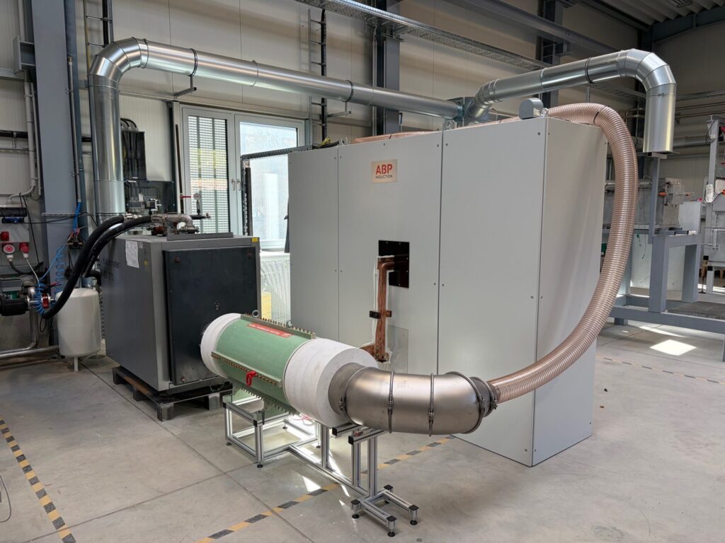
The concept was developed at the Foundry Institute of TU Freiberg. To bring the technology from the lab into real-world application, an alliance was formed: the university as the originator and development partner, Primetals as the system integrator, and ABP Induction for induction technology, contributing its insights in control systems, coil design, and power supply. Following successful lab trials with power levels between 10 and 35 kilowatts, an industrial demonstrator rated at 200 kilowatts is currently undergoing testing, serving as the foundation for market entry (Figure 3). The results demonstrate that the system is scalable — from compact applications to large-scale processes in the steel industry as well as glass, ceramics, and chemical.
Figure 3. UHT Thermo Jet UHT200® — test facility for 200kW heating power | Image Credit: TUBAF University of Freiberg
The UHT Thermo Jet transfers the principle of induction to indirect process heat. While previous systems exclusively heated metallic workpieces directly, the new technology now enables controlled generation of hot gas streams — a decisive step toward full electrification of industrial heat supply. By combining efficiency, responsiveness, and sustainability, this solution paves the way toward a CO2-neutral future while ensuring cost-effective operation.
3 Stages: Technical Application Development
The development of hybrid heating systems follows a clear technological logic:
In the short term, fossil-based systems are supplemented by complementary induction modules.
In the medium term, they are replaced by electric heat sources, such as the UHT Thermo Jet.
In the long term, they are fully electrified.
This evolution creates multiple advantages: first and foremost, a rapid entry into decarbonization through the retrofit of existing systems, resulting in lower operating costs due to reduced gas consumption and decreased maintenance requirements. This also leads to an increase in product quality thanks to precise temperature control. Companies also stand to benefit from the energy transition in the market, with long-term supply security, as electricity from renewable sources can be generated locally.
At the same time, new requirements are emerging for control and integration. Electric heating systems respond instantly to grid fluctuations and can be integrated into digital energy management systems. This makes it possible to optimize load profiles, adapt production processes flexibly to energy availability, and manage energy consumption with full transparency — a key milestone on the path to climate-neutral industrial production.
The ecological impact of hybrid heating systems is thus directly measurable. By partially replacing fossil burners, CO2 emissions can be reduced significantly. At the same time, nitrogen oxide and particulate emissions, which are typically generated during combustion, are reduced.
The economic picture is similar; while the investment costs for electric systems are higher, operating costs decrease due to lower gas consumption and improved energy efficiency. In addition, expenses for emission certificates, burner maintenance, and exhaust gas treatment are eliminated. In many cases, the investment pays off within a few years, especially when funding programs for the decarbonization of industrial processes are utilized.
In addition, the resilience of production systems improves. Electrically operated systems are less dependent on geopolitical energy imports and can potentially be powered directly by locally generated green electricity or by synthetically produced energy (via power-to-X processes) in the future. New energy storage concepts will also play a role here.
Practical Considerations
There are four key megatrends in industry: digitalization, deglobalization, demographic change, and decarbonization. Electrification of process heat is a key area of action, following the three-stage logical flow to implement fully electric, CO2-free process heat solutions. This approach reflects the reality in many industrial enterprises, which, due to their investment cycles, cannot implement an immediate transition. Hybrid solutions provide the essential bridge — both technologically and economically.
Despite these innovations, it is clear that the transformation of industrial process heat will not happen overnight. It requires time, investment, and a high degree of technical integration. Nevertheless, the electrification of thermal processes is considered an indispensable component of industrial decarbonization.
Hybrid heating systems represent a key enabling technology in this context. They enable the gradual replacement of fossil fuels, increase efficiency, and open up new degrees of freedom in production control. With innovations such as the UHT Thermo Jet, the range of applications expands significantly — reaching into areas like process gases and high-temperature applications that were previously considered the domain of fossil combustion.
Hybrid technology does not mark the end, but rather the beginning of a new generation of industrial heating systems — efficient, flexible, and climate-neutral.
About The Authors:
Dr.-Ing. Marco Rische Chief Technical Officer and Director System Business ABP Induction
Dr.-Ing. Marco Rische is a highly qualified professional in induction heating systems technology with over 26 years of experience as the vice president of service, chief technical officer (CTO) and director system business with ABP Induction. He has demonstrated a deep technical understanding as a leader, leveraging his management and engineering background to solve complex technical and organizational challenges.
Dr. Martin Ennen Application and Development Engineer ABP Induction
Dr. Martin Ennen has studied electrical engineering and obtained his PhD in the field of electrical process engineering, with a focus on inductive heating processes. He has been working for three years at ABP as an application and development engineer. He is responsible for research and development work that entails numerical process simulation leveraging state-of-the-art FEM methods.
Whether you need insight on enhancing your energy utilization, managing induction systems (troubleshooting), or prolonging equipment longevity, today’s Technical Tuesday original content feature will keep you well-informed.
Heat TreatToday has coalesced technical information across articles from key experts, including tips to improve your energy efficiency, a walk-through guide for troubleshooting your induction system, and ten practical tips for improving your equipment longevity.
Induction and Sustainability Tips Part 2: Efficient Power
As energy efficiency becomes a driving force in modern heat treating, manufacturers are turning to smarter induction technologies to cut waste and lower costs. In this second installment of Heat Treat Today’s sustainability series, explore how AC-to-DC conversion, intelligent power feedback systems, and advanced diagnostics can transform your induction heating setup into a cleaner, more consistent, and cost-effective process.
“Furthermore, transformers operate at optimal efficiency when under a reduced load – i.e., less than 70% output in steady-state heating – rather than ramping up to the full operating temperature. Another advantage of the DC-type transformer is that its operating power factor is very close to 1.0, which lowers the utility company’s calculation of peak demand surcharges.”
Facing erratic heating, poor consistency, or unexpected shutdowns in your induction system? This comprehensive guide walks heat‑treat operators through a ten‑step diagnostic framework for identifying and resolving common induction issues.
Figure 2. Induction
system components Source: Contour Hardening, Inc.
“The induction process involves many characteristics such as: position of the piece within the induction coil, load positions, cooling positions, cycle times, applied electric power, and others. It is important that the professional can identify the failure and the particular situation at the moment in which it is occurring.
On some occasions, the failures are not evident and therefore it is essential to analyze the part that has been treated. This analysis can be key to understanding situations such as poor depth due to electrical power or decrease in output frequency, among other possible scenarios.”
New and Improved Tips for Induction Equipment Longevity
Heat treaters are always looking for ways to extend the life of their induction tools, but what methods are proven maintenance strategies? Focusing on the durability of coils, bus bars, inductors, and quench components, this technical article will give you practical and reliable tips to promote longevity in your equipment.
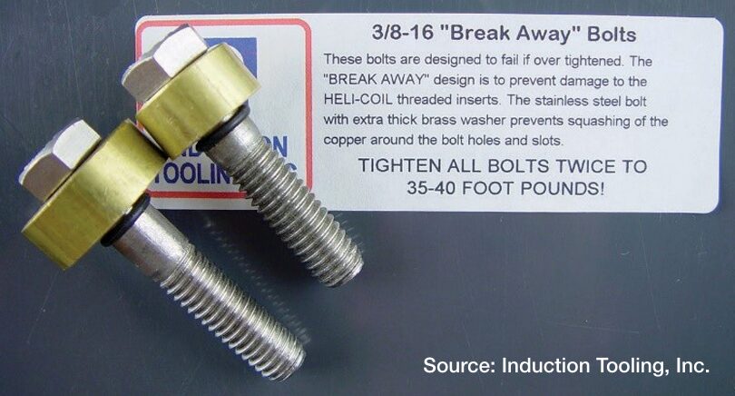
Figure 2. Break-Away bolts designed to fail beneath the washer if over tightened
“More than coils — When working to optimize the life of induction equipment, don’t focus solely on the coils. Bus bars, inductors, and quenching equipment are also key to success.
Austenitic stainless steel — Use austenitic stainless steel for fasteners, fittings, and hose clamps, and remember, non-ferrous is the way to go.
CNC machining — Manufacturing with a 5-axis CNC machine ensures quality and consistency.
“Break-Away” bolts — For fasteners, use “Break-Away” bolts on contact surfaces. These bolts are designed to fail beneath the washer if they are overtightened, a design that prevents damage to the threaded insert inside the copper contact.”
By Jose Miguel Equihua Toral, Head of the New Projects and Development, BOINSA Mexico and Manager,InTech NDT, USA.
Nondestructive testing (NDT) techniques have been used exclusively to detect defects in structures and components after they have been manufactured. To protect public safety and security, it is imperative to test parts efficiently and ensure their quality. Nondestructive evaluation, like ultrasonic backscattering, serves an important role in this area.
This informative piece was first released inHeat TreatToday’sApril 2025 Annual Induction Heating & Melting print edition.
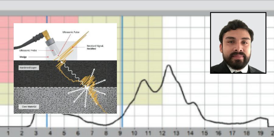
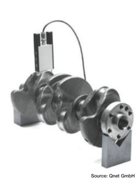
Induction hardening is a critical process in manufacturing automotive, agricultural, and aeronautical components, such as crankshafts, camshafts, constant velocity joints, and axle shafts (Figure 1a). The procedure for the evaluation of metallurgical characteristics is carried out in the laboratory and is destructive testing (Bernard, “Methods of Measuring Case Depth in Steels”). This means the component will be unusable. Additionally, this procedure is time-consuming, expensive, and cannot be integrated into the production line. Over time, the industry has sought faster and more efficient methods to evaluate metallurgical characteristics, such as eddy current testing, magnetic methods, and ultrasound. Having the capability of monitoring material properties after each key process can help minimize the cost of processing out-of-specification material. A combination of nondestructive testing methods can help to guarantee the quality of induction heat treatment operations (ASM Handbook, vol 4c).
Ultrasonic methods, for example, can be used to determine microstructural differences in metals. For this, contact testing with pulse-echo technique is used. For inductive-hardened parts, the ultrasonic backscattering method works because the hardened layer (martensite) is almost transparent to ultrasonic waves (in range of 20 MHz), while bulk material (ferrite-pearlite) scatters ultrasonic waves very strongly.
In this article, we will address the use of industrial ultrasound applying the backscattering technique, which offers a direct determination of the depth. This method is simple and does not require prior calibration to evaluate the components (Figure 1b).
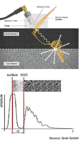
Iron crystals exhibit notable acoustic anisotropy, meaning the acoustic velocity (c) varies depending on the direction of travel within the crystal. Grain boundaries represent transitions between crystal structures with varying orientations. The resulting variation in impedance causes the ultrasonic pulse to scatter at the grain boundaries. The ultrasonic technique for measuring hardness depths (SHD) utilizes this grain boundary scattering effect. This technique is known as the ultrasonic backscattering method (Kruger et al., “Broadband Ultrasonic Backscattering”).
The ultrasonic backscattering method for hardness depth testing relies on finding the ultrasound frequency that does not scatter at the fine-grained hardened microstructure of the outer layer but at the coarse-grained core material (Figure 2a). The different scattering properties from the varied grain sizes of the hardened surface layer and the core material are seen in the backscattering measurement. The connection between scattering and the material’s grain size is utilized to produce a detectable backscattering echo when the ultrasound penetrates the core material.
The depth (SHDUS) of the interface can be determined using the time (t) it takes for the sound pulse to reach the scattering interface, the angle of the shear wave (βT), and the velocity (c) of the shear wave in steel. Therefore, the following equation is relevant for a flat shape:
SHDUS=1/2∙c∙t∙cos∙βT
Based on this equation, the acoustically measured surface hardness depth (SHDUS) is always found before the sound exit point of the probe wedge. To guarantee an accurate measurement of this location during destructive testing, this distance (A) must be calculated. The next equation is used for a plane geometry:
A=1/2∙c∙t∙sin∙βT
The backscattered ultrasonic amplitude depends on the actual gradient of the microstructure. In the transition zone, grain boundaries, grain size, and second phases change the acoustic impedance value discontinuously, depending on the ultrasonic frequency. Different backscattering signals in the hardened and bulk material occur (Yanming Guo, “Effects of material”). Th ese amplitude characteristics can be used to evaluate the case depth by using simple time-of-flight measurements (Figure 2b). Contact testing is generally done by using portable equipment, using a contact wedge where the transducer is mounted to be inclined at a certain angle, and shear waves are emitted into the component. Ultrasonic backscatter takes place at the surface of the component due to surface roughness and results in the return of the energy to the transducer (first echo). Ultrasonic energy enters the hardened surface layer made of fine martensitic structure, and thus, no scatter of ultrasonic waves takes place in this region. However, when the shear waves reach the transition zone where martensitic structure is gradually converted into ferrite-pearlite structure, which has a larger grain size, once again energy is scattered at the grain boundaries, and the transition zone backscatter forms the second echo. The difference in time-of-flight of these two echoes is proportional to the case depth of the component.
Technical Requirements
Technical requirements for testing hardness depth using the ultrasonic backscattering method will produce optimal results in the following conditions:
The test parts should be induction-hardened.
The test parts must be forged, not cast.
There is minimal or no microstructure present between the hardened martensitic microstructure and the core material.
The grain size of the core material is significantly larger than the grain size of the hardened microstructure, leading to considerable backscattering of shear waves at a frequency of 20 MHz.
The minimum hardness depth that can be measured is 1.2 mm. Smaller hardness depths need special considerations, such as adjustments to the wedge design.
Practical Correlation Between NDT and DT
Destructive hardness depth testing is a method to determine the thickness of the case depth of hardened parts. In the process, the parts are destroyed, or their surface is altered rendering each tested part unusable. Hardness depth profiles are usually determined by using the Vickers test to measure the hardness of a reference sample at different points in a line from the surface to the core.
If you compare the acoustically measured surface hardness depth SHDUS with the surface hardness depth measured with destructive methods SHDDT, you will see a basic difference: Independent of the hardness limit and the minimum hardness, the acoustic testing always determines the depth of the core material that has not been affected by the hardening process. As a consequence, this value tends to be slightly higher than the surface hardness depth measured with destructive methods SHDDT. This difference can be compensated by means of a correction term ΔT (“Off set”):
SHDUS = SHDDT – ΔT
In the case of hardness curves with rapidly decreasing hardness values just above the interface, the transit time is measured at 20% of the height of the backscattering signal’s amplitude, and the results of the acoustic and the destructive hardness depth tests will match. The reason for this is the slightly shorter sound path in the marginal ray of the divergent sound field, which induces the backscattering echo.
If cases occur regularly in which the hardness curve deviates significantly from the characteristics, reference tests must be conducted to determine the correction factor ΔT. Reasons for this could be material and/or process related. The calculated correction factor can then be integrated in the respective test task as a test parameter.
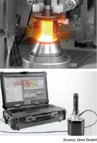
Technical Description and Measurement Highlights
The manual device includes a four-channel ultrasonic board managed by a software package for program settings, signal processing, reporting, and overall quality assurance requirements. The parts are put together in an industrial notebook meant for tough industrial settings. The probe systems allow testing of components with complex shapes. The wedge of the probe system is adjusted to fit the geometry of the specific test location. Testing can be done before or after machining.
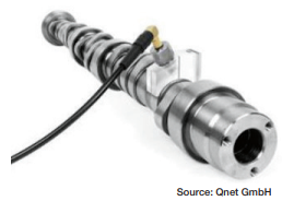
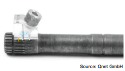
The primary cause of measurement error is the evaluation of surface position; the shape of the surface signal relies on proper coupling and the operator’s skill. Another source of error is the placement of the marker that indicates the time-of-flight when the pulse hits the interface. The sharper the signal rises, the less the error. Therefore, a shear wave angle as low as reasonable is employed, and scanning in the direction of decreasing SHD is advised. Achievable accuracy of better than ±0.1 mm is possible for standard parts with high-quality surfaces. Nevertheless, the operator must monitor the “good” shape of the A-scan during data collection. Accuracy based on microindentation hardness profiles compared to the backscatter method is slightly lower, estimated at ±0.2 mm on average, based on the material microstructure (Bogaerts et al., “Surface Hardness Depth Measurement”). We are able to test different geometries like crankshafts (Figure 3), camshaft s (Figure 4), tulips (Figure 5), and barshafts (Figure 6), to mention some components.
Situation: During induction hardening, an unanticipated variation on the case depth was detected on the shaft of an axle bar (Figure 7). We were requested to examine the case depth in this important area using a P3123 Hardness Depth Tester to find out if the case depth met specifications.
Figure 7. Induction case-depth variationFigure 8. Axle bar inspection
Results: During the testing, we noted the case depth was insufficient compared to the minimum required case depth of 5.5 mm. This meant all induction hardened parts made before the discovery had to be paused while a complete check of the case depth was performed. All axle bars hardened after the discovery were analyzed (Figure 8), starting with the most recently hardened parts. Case depth was also evaluated by making a microindentation hardness profile in the hardened area, showing a case depth consistent between ultrasound readings with the P3123 and the destructive testing measurements. In Figure 9, we can observe the measurement of the out of specification case depth, and in Figure 10, we have the measurement within specification case depth.
Hardness depth testers are used for optimizing production parameters, reducing downtimes after inductor changes, fast production control, and quality management. The techniques discussed in this article offer the technical advantages to ensure quality assurance for both steel and induction hardened components. Feasibility testing is required, which can be performed with prompt review of the ultrasound behavior in components.
Figure 10. Case depth within specificationFigure 9. Case depth out of specification
Bernard, William J. “Methods of Measuring Case Depth in Steels.” Steel Heat Treating Fundamentals and Processes (2013): 405-416. https://doi.org/10.31399/asm.hb.v04a.a0005795.
Bogaerts, Mike, Michael Kroening, Paul Kroening, and Tobias Mueller. “Surface Hardness Depth Measurement Using Ultrasound Backscattering.” AM&P Technical Articles 177, no. 8 (2019): 58-62. https://doi.org/10.31399/asm.amp.2019-08.p058.
Guo, Yanming. “Eff ects of material microstructure and surface geometry on ultrasonic scattering and fl aw detection.” Dissertation, Iowa State University, 2003.
Kruger, S.E., J.M.A. Rebello, and J. Charlier. “Broadband Ultrasonic Backscattering Applied to Nondestructive Characterization of Materials.” IEEE Transactions on Ultrasonics, Ferroelectrics and Frequency Control 51, no. 7 (2004): 832-838. https://doi.org/10.1109/tu c.2004.1320742.
About The Author:
Jose Miguel Equihua Toral Head of New Projects and Development BOINSA Mexico Manager, InTech NDT, USA
Jose Miguel Equihua Toral graduated as a mining engineer from Guanajuato University and obtained his Master’s Degree in Engineering from the National Technology Institute of Mexico. He currently works as head of the new projects and development department of BOINSA de Mexico, involved in technological and operational advances in the design, manufacture, and repair of induction coils, as well as advances in the application of non-destructive testing methods for the quality assurance of components for the automotive, agricultural, and energy industries. This experience has led to the formation of InTech NDT, to serve the U.S. market.
For more information: Contact Jose Miguel Equihua Toral at miguel.equihua@intech-ndt.com.
What is missing from induction heat-treating maintenance? Learn seven methods for improving your induction tooling component performance in today’s article by David Lynch, Vice President of Engineering at Induction Tooling, Inc.
This informative piece was first released inHeat Treat Today’sApril 2025 Annual Induction Heating & Melting print edition.
The heat-treating industry is constantly evolving, whether it is due to the influx of AI or the introduction of new materials. The field of induction is not exempt from this constant change. Yet there remains a constant — induction tooling components need to be tough to resist harsh environments comprised of high frequencies, high power, heat, smoke, steam, dirt, oil, quench fluid and additives, and contaminants. It’s been almost four years since we visited the topic of induction tooling equipment longevity and maintenance (see the May 2021 print edition). Amidst the constant change, how do we protect against the same old toxic environment?
Let’s explore some new methods of improving the performance and longevity of induction tooling components:
Figure 2. Break-Away bolts designed to fail beneath the washer if over tightened
More than coils — When working to optimize the life of induction equipment, don’t focus solely on the coils. Bus bars, inductors, and quenching equipment are also key to success.
Austenitic stainless steel — Use austenitic stainless steel for fasteners, fittings, and hose clamps, and remember, non-ferrous is the way to go.
CNC machining — Manufacturing with a 5-axis CNC machine ensures quality and consistency.
“Break-Away” bolts — For fasteners, use “Break-Away” bolts on contact surfaces. These bolts are designed to fail beneath the washer if they are overtightened, a design that prevents damage to the threaded insert inside the copper contact.
Cooling water — For cooling the inductor coil, bus bars, and adapters, reverse osmosis and distilled and deionized water are overkill. Stick with keeping the water below 70°F. This may require a separate cooling supply. Through laboratory experimentation and real-world production trials, it has been proven that lower cooling water temperatures can drastically increase the life of these components, especially in high-volume, high-power, and short cycle applications. In some hard water areas, this may not be possible. Typical cooling-conductivity for the inductor and bus bar is 200–800 microsiemens per centimeter (μS/cm).
Non-ferrous fittings — Use non-ferrous fittings on cooling and quenching water connections, as well as color-coded hoses.
Cleaning — Design with cleaning in mind. Designing a quench with bolted removable quench plates ensures easy clean out. As the heat-treating industry continues to evolve, our practices and technologies for optimizing the performance and longevity of induction tooling equipment evolve with it. Whether it’s using a new method or revamping a tried-and-true practice, we can continue to produce strong induction tooling components to sustain these harsh environments.
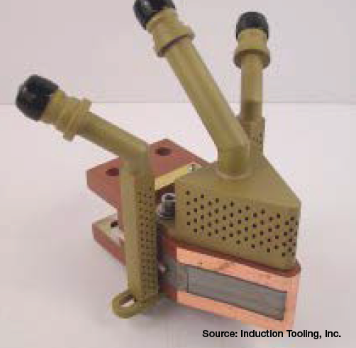
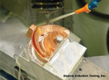
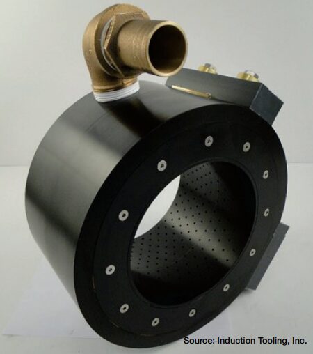
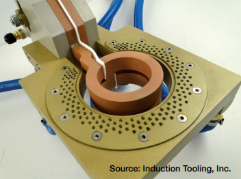
Figure 3. 5-axis CNC machining of water-cooling passages to maximize water flow and minimize sharp transitionsFigure 4. CVJ inductor with non-ferrous fittings and color-coded hoses on cooling and quench water connectionsFigure 5. Barrel style OD quench ring with bolted removable quench plates to allow easy clean outFigure 6. Multi-turn OD scanning inductor with integrated quench featuring removable quench plate for easy clean outFigure 7. Heavily used inductor
About The Author
David Lynch Vice President of
Engineering Induction
Tooling, Inc.
David Lynch is Vice President of Engineering at Induction Tooling, Inc. He has over 36 years of experience and is the deputy of the ISO quality system. He has created and developed the system and templates being used today for creating and tracking engineering drawings, job history, rate tracking, and job performance. David holds several design patents, has authored several published articles, and has often presented at technical sessions. He enjoys working closely with customers to develop valued solutions across a wide range of induction heating applications from initial design concepts to implementation, customer support, and troubleshooting.
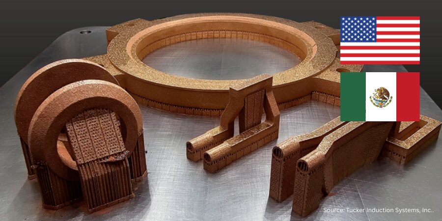
In this Technical Tuesday installment,Josh Tucker, manager of Induction Heating, Tucker Induction Systems, Inc., relates new research conducted on the strength of coils which have been produced through 3D printing.
This informative piece was first released inHeat Treat Today’sApril 2025 Induction Heating & Melting print edition.
Research on 3D printing induction coils finds that coils are stronger and have a longer life when compared to traditionally manufactured coils. Read about how additive manufacturing removes steps like brazing the joints and provides new design capabilities.
Tucker Induction Systems began exploring the possibility of using 3D printing technology to manufacture coils and found that, in many cases, 3D printed coils were stronger and longer lasting than traditionally manufactured counterparts.
The quest to develop 3D printed coils began in 2020. When COVID-19 hit, Macomb County, Michigan, started an initiative called Project DIAMOnD, which stands for Distributed, Independent, Agile Manufacturing on Demand. It provided small-to-medium-sized area manufacturers with Markforged Fused Deposition Modeling-style 3D printers as both a way to quickly manufacture much needed personal protective equipment for the pandemic and to help small-to-mid-sized manufacturers overcome the supply chain issues that plagued industry during the crisis.
We were eager to gain hands-on additive manufacturing experience through the DIAMOnD initiative and, in doing so, found that it sparked our curiosity about the possibility of 3D printing our coils and new ways to design them that go beyond the capabilities of traditional machining.
In 2021, we began a two-year research and development process of printing coils and discovered that by 3D printing induction coils we were able to drastically increase the strength of the coils and potentially lengthen the useful life of the coil. The experience has opened new realms in designing our coils, as well as giving us the ability to design coils using methods that go beyond the capabilities of traditional machining.
It is common industry knowledge that the weakest parts of a coil are the braze joints, but through the R&D process, we have learned that by 3D printing the coils, it is possible to eliminate most, if not all, braze joints in the head of a coil. This increases the strength and, potentially, the life of a coil. After years of testing and evolving, the end results were better than we expected, proving that the coils can be printed and will last in the field.
Figure 1. 3D printed single-shot hardening induction coil heads
However, there were some challenges in adapting to using 3D printing technology. For example, the type of copper printing we required was not being done in the United States, which was an obstacle in trying to form a process that resulted in a successfully printed coil. But one of the biggest challenges after we locked down the process and material was in designing the internal cooling passages for the coils. The passages needed to be designed in a way that was self-supporting and non-restricting. We had to produce the same flow rate as traditionally made coils and ensure we were driving the cooling into the right areas. Figuring that out took many failed attempts — learning opportunities — before achieving success.
Once that goal was achieved, we installed a metal 3D printer at Tucker Induction in January 2024 and have been successfully printing all different types of coils. Some examples include two turn ID, spindle, single-shot, and scanning coils.
The Benefits of Using 3D Printed Coils
While traditional coils (such as our interchangeable, quick-change coil for two-turn induction systems and single-shot designs with accurate clamping pressure) have changed the industry, the additional capability of 3D printing allows us to print dimensionally accurate, durable parts that are capable of performing in the field and that can go beyond the barriers of traditional machining.
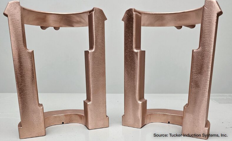
Figure 2. 3D printed single-shot induction coil with keepers
3D printed coils bring several worthwhile benefits to the table including time savings, longevity, and faster coil repair. Time savings is one of the biggest advantages. Because the 3D printer can run “lights out,” the processing time from the printer to the client is far shorter when compared to traditionally fabricated coils. We refer to the processing time as the additional time needed to complete the coil assembly after printing. In some situations, it is possible to print a completed coil assembly with the coil immediately ready to be sent to the client. Other times, additional brazing or supplemental details may be required to complete the assembly.
Since all coils are different, the processing time varies from coil to coil. However, by printing as much of the assembly as we can, we are able to limit the amount of additional work needed to complete the job.
Strength and potential longevity of 3D printed coils are additional advantages. The weakest parts of the coil are the braze joints, but the process we use to print the coils drastically reduces the amount of braze joints, thus making the workforce of the coil a solid construction. This results in a product that will be stronger in the induction environment and has the potential to outlast its traditionally manufactured counterpart.
When it comes to the lifetime of the 3D printed coils, our baseline is that the printed coils need to last at least as long as traditionally manufactured coils. However, in our research, we have seen, on average, that our 3D printed coils can last two to three times longer than traditionally manufactured coils. While the longevity of each coil is case dependent, as there are many factors that go into the lifespan of a coil, one of our original test coils is still running in the field with over one million heat cycles.
While continuing to improve processes and designs, we are also pushing to decrease the time for repairs. Getting our clients’ coils repaired and returned in an effort to limit their downtime has always been something we strive for with our traditional coils, but we have found that 3D printed coils are easier to repair. Since multiple braze joints are not an issue in printed coils, it reduces the chance of causing additional problems as you work on the original repair. If the repair consists of replacing the head of the coil, we are able to recall the original print and run it again, as opposed to having to re-machine and re-assemble and braze the entire coil, significantly reducing the repair time of many 3D printed coils.
Limitations of 3D Printing Coils
Despite the advantages of 3D printing induction coils and the fact that the capability to print coils gets you into the mindset that every coil needs to be printed, there are some instances when it is still more effective to use traditional manufacturing.
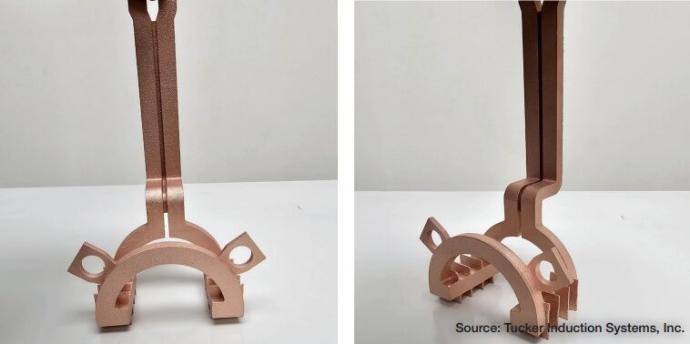
Figure 3. 3D printed sample structures
For example, coils that are larger than the machine is capable of printing — our print bed size is roughly 12 x 12 x 13 inches — can be a limiting factor. Other times, the coil may be manufactured faster using traditional methods. The printer does have limitations, and it is not the best option for certain coils. For example, coils that are less intricate and made from tubing is one type that would be a better candidate for traditional manufacturing; these coils simply require wrapping copper tubing around a mandrel.
The Future of 3D Printed Coils
We are continuing to research and fine tune the processes of 3D printing our coils and strive to provide our clients with the best possible product. In order to do that, we must stay vigilant and be willing to continuously learn and improve our designs and processes.
As we learn more and perfect our 3D printing coil processes, I believe 3D printed coils will play a vital role in the future of the industry. We have proven that 3D printing coils is not just possible, but that in some cases 3D printed coils can outperform their traditionally manufactured counterparts.
About The Author:
Josh Tucker Manager of Induction Heating Tucker Induction Systems, Inc.
Josh Tucker graduated with a bachelor’s degree from Grand Valley State University and was then hired as the head of Purchasing at Tucker Induction Systems. Since starting eight years ago, Josh’s role and capabilities have expanded to machining, wire EDM, 3D printing, and laser engraving. He also organizes the day-today operations and flow of the shop floor. Josh was recognized in Heat Treat Today’s 40 Under 40 Class of 2024.
As we get further into the heart of fall, it’s time to turn up the heat (treat)! – but how can this be done in an optimized and sustainable way?
Today’s Technical Tuesday original content round-up features tips and tricks from our summer print editions on how to optimize and sustain your heat treat operations, even during the chilly months. So, bundle up, grab a hot drink, and review these insightful pieces!
Sustainability Insights Corner
In May, Heat TreatToday began publishing "Sustainability Insights" from the IHEA editorial team. Here's a brief overview of the recent insights all in one place:
June: NEW Sustainability and Carbonization Webinar Series. Although this year's IHEA Webinar series may have come and gone, it's not too late to establish a foundational understanding of carbon and sustainability here!
August: Reducing the Carbon Footprint of Your Heat Treating Operations. Brian Kelly of Rockford Combustion is back with yet another suitability insight, here exploring ways to assess your heat treating operation's carbon footprint, tune your combustion systems, explore renewable fuels, and much more.
September: Process Heating and the Energy-Carbon Connection. Explore the issue of greenhouse gases and how recent conversations are affecting the heat treating industry with Michael Stowe of Advanced Energy.
In Case You Missed the May Issue: Induction and Sustainability Tips
Looking for sustainability tips for your heat treating operation, but lacking in time? Heat TreatToday's May Issue has you covered with a quick read: "13 Induction and Sustainability Tips." We'll highlight a few below which made it into a recent Technical Tuesday feature:
Sustainable Energy for Furnaces? What does the Future Hold?
What will the future run on? With growing discontent around current energy sources like natural gas and other fossil fuels, power sources for furnace equipment are due for a makeover.
Explore the question of sustainable energy for furnaces in the future with industry experts John Clarke of Helios Electric, Philippe Kerbois of Glass, various authors from Watlow, and Stuart Hakes of F.I.C. (UK) Limited.
How much electrical power is being used in the typical heat treatment plant? And how can power (and money) be saved in these operations? If these questions peak your interest, explore further with Roger A. Jones and William Jones of Solar Atmospheres.
Learn about savings in electricity and money in areas of electric motors, high vacuum diffusion pumps, gas blowers, building lighting, AC/heating, and more in this article.
Discover expert tips, tricks, and resources for sustainable heat treating methods Heat TreatToday’srecent series. Part 4, today’s tips, covers induction heating, quench, and insulation tips. We’ve added resources towards the end of today’s post for further enrichment.
This Technical Tuesday article is compiled from tips in Heat TreatToday’sMay Focus on Sustainable Heat Treat Technologiesprint edition. If you have any tips of your own about induction and sustainability, our editors would be interested in sharing them online at www.heattreattoday.com. Email Bethany Leone at bethany@heattreattoday.com with your own ideas!
1. Tips for Induction Hardening
Contact us with your Reader Feedback!
What are the benefits of induction hardening? Here are a few:
Saves space: Induction hardening requires minimum space required in comparison with furnaces
Saves energy: Induction heating equipment does not need to be kept running when not in use
Clean: Induction heating equipment requires no combustion gases
Energy-efficient: Only a small proportion of the material needs to be heated
Minimize deformation: Induction hardening requires no applied force
Save maintenance costs: Inductor coils have a long life, reducing the need for maintenance
Source: Humberto Torres Sánchez, Chief Metallurgist, ZF Group
2. Insulation = Key for Energy Savings in Vacuum Furnaces
Look for insulation quality in your next vacuum furnace.
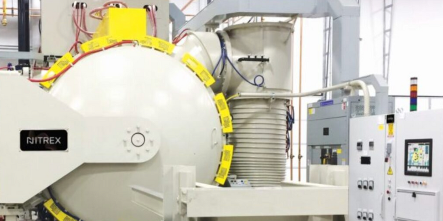
Source: NITREX
Improvements in insulation materials are also contributing to greater energy efficiency of vacuum furnaces. Most furnaces on the market today have a 1” (25.4 mm) graphite board with bonded Grafoil and two layers of graphite felt. However, the insulation performance of a 1” (25.4 mm) graphite board is about 25% less efficient than a 1” (25.4 mm) graphite felt. For processes that require high operating temperatures, typically over 2,200°F (1,204°C), an all graphite felt that is 2” or 2.5” thick (50.8 mm or 63.5 mm) minimizes heat loss inside the hot zone. Efficiency gains of up to 25% are possible over the standard 1” (25.4 mm) board and 1” (25.4 mm) graphite felt insulation and an even greater gains at higher operating temperatures. To safeguard the graphite felt from mechanical harm and localized compression, these thicker all-graphite felt insulation configurations are usually covered with a carbon fiber composite (CFC) sheet about 0.050” (1.27 mm) thick.
Fuel efficiency (and the stringent requirement for passenger safety) has raised the bar for the automotive industry to procure steel with high strength, hardness, and ability to fabricate. Reduction of weight requires lighter cars with thinner body material which can absorb impact. These dual contradictory properties of high hardness material which can be easily shaped can normally be achieved either by heat treat or through addition of alloys. These two processes are described below.
Normal heat treatment to produce small grains in the material will increase the hardness in steel but also create a propensity to fracture. Thus, a process known as quench and partition — where carbon diffusion from martensite to retained austenite to stabilize the latter — has been introduced. Further verification and prediction of the phases has been conducted using thermodynamics modeling for phase characteristics by Behera & Olsen at Northwestern University, Materials Science and Engineering.
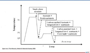
The process starts with full automatization (or in some cases intercritical annealing) followed by fast quench to a defined quench temperature (QT) between the martensite start, Ms, and martensite finish, Mf, temperature. The steel is then reheated to the partition temperature (PT) and held there for a certain partition time followed by a quenching step again to room temperature, as shown in the image.
Quench and partition process
Source: Speer et al. The Minerals, Metals, & Materials Society 2003
The quenching step establishes the largely martensite matrix while the partition step helps stabilize the retained austenite by carbon partitioning. During the holding step, carbon diffuses from martensite to retained austenite and thus improves its stability against subsequent cooling or mechanical deformation. The final microstructure consists predominantly of tempered martensite and stabilized retained austenite with possibly a small amount of bainite formation and carbide precipitation during the partition step and fresh martensite formation during final quenching.
The other process to achieve high hardness and high ductility is by alloy addition in carbon steel. Over, 2,000 different types of steel exist. A new type of steel that is extremely strong, but simultaneously ductile is used in the automotive industry. Small quantities of elements like vanadium or chrome in steel promotes ductility. They are not brittle; however, up until now they have not been strong enough to enable the construction of car bodies with thinner sheets.
In the crystals of steels, the atoms are more or less regularly arranged. Steels become particularly ductile though if they can switch from one structure to another. This is because this process allows energy absorption, which can then no longer initiate any damage in the material. In a car body or other steel components, tiny areas then alternate with the two different atom arrangements.
Ductile steels have two coexisting crystal structures. The search produced an alloy made from 50% iron, 30% manganese and 10% respectively of cobalt and chrome (Max Planck Institutes).