INDUCTION HEATING TECHNICAL CONTENT

Dr. Valery Rudnev on . . . Equipment Selection for Induction Hardening: Continuous & Progressive Hardening, Part 1

This article continues the ongoing discussion on Equipment Selection for Induction Hardening by Dr. Valery Rudnev, FASM, IFHTSE Fellow. Previously, Dr. Rudnev reviewed equipment selection for scan hardening in three parts. This first installment in a new sub-series addresses equipment selection for continuous and progressive hardening. The second part in this series on equipment selection for continuous and progressive hardening is here; the third part is here. To see the earlier articles in the Induction Hardening series at Heat Treat Today as well as other news about Dr. Rudnev, click here


Introduction

The hardening of steels, cast irons, and P/M materials represent the most popular application of induction heat treatment. There are four primary methods for induction hardening [1]:

  • Scan hardening,
  • Continuous and progressive hardening,
  • Static hardening, and
  • Single-shot hardening.

These methods are related to the heating mode, essentials of inductor design, part geometry, and processing specifics. The previous three installments of this column, “Dr. Valery Rudnev on …”, discussed select subtleties associated with induction scan hardening. This article is devoted to continuous and progressive induction hardening techniques.

Continuous and Progressive Hardening

This method is commonly applied when heat treating elongated workpieces, such as bars, tubes, rods, wires, plates, beams, pins, and others. Long parts are more readily processed in a horizontal manner and heated as they progressively pass through multiple inductors. Inductors are positioned in-line or side by side. Each inductor may have a different design and power/frequency setting. This type of hardening is not limited to horizontally processed parts; vertical processing and arrangements at certain angles are also possible, if suitable.

There are also cases when a workpiece is statically heated to a certain temperature and then progressively moved to another heating position or static inductor for the next heating stage. These processes are referred to as progressive processing/heat treatment.

Induction practitioners sometimes consider continuous or progressive horizontal hardening systems as horizontal scanners. The difference is vague and it is a matter of terminology. Some heat treaters feel that it would be appropriate to differentiate these systems based on the number of inductors included in the induction machine design. Horizontal systems consisting of a single inductor are commonly referred to as horizontal scanners. In contrast, if a system consists of two or more heat treat inductors, then it might be referred to as a continuous or progressive heat treat system.

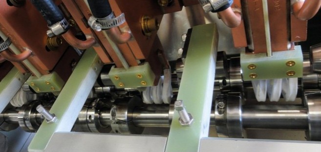
With the continuous hardening method, the workpiece is moved in continuous motion through a number of in-line inductors. Multiturn solenoid coils and, to lesser a degree, channel-style inductors and split-return inductors are most typically used in continuous heat treating lines. As an example, Figure 1 shows a side view of a horizontally arranged continuous induction system consisting of three in-line coils. Each coil consists of three turns.

Figure 1

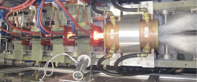
As another example, Figure 2 shows a top view of a continuous heat treating line that comprises four in-line hardening coils and a spray quench device positioned after the last inductor. Workpieces (e.g., bars, shafts, rods, pins, etc.) are processed end-to-end through the inductors in a continuous motion.

Figure 2

Progressive multi-stage hardening is used when multiple workpieces are moved (via a pusher, indexing mechanism, robot, walking beam, etc.) through a number of coils. Therefore, the entire component or its portions are sequentially heated (in a progressive manner) at certain predetermined heating stages inside the in-line horizontal (being more typical) induction heater or a multi-position horizontal or vertical heater where coils are positioned side by side.

Continuous or progressive hardening methods are typically used for through hardening of elongated or moderate-length parts processing end to end and, to a lesser degree, for surface hardening. Outside diameters for case hardening (surface hardening) usually vary from 1/2 in. (12 mm) to 4 in. (100 mm). In through hardening applications of solid cylinders, the diameters may be as small as 1/8 in. (3 mm).

It is possible to recognize three heating stages in through hardening applications [1]:

  1. Initial or magnetic stage,
  2. Interim stage, and
  3. Final heating stage.

Initial or magnetic stage. Temperatures anywhere within the workpiece are below the A2 critical temperature (Curie point); thus, the steel is ferromagnetic and the current penetration depth is typically quite small. Skin effect is fairly pronounced at this stage and the heat source distribution resembles a conventional exponential distribution. The maximum power density is located at the surface and sharply decreases toward subsurface and the core. Heat source generation is localized by the fine surface layer of the workpiece. This leads to a rapid increase in temperature at the surface with a minor change in the core. This stage is characterized by high electrical efficiency often reaching 90% or so.

Interim stage. During this stage, the austenized surface layer and near-surface area is heated above the A2 critical temperature; however, the internal region, having temperatures below the Curie point, retains its ferromagnetic properties. At this stage, the power density distribution along the radius has a unique non-exponential “wave-like” distribution, which is very different from the commonly assumed exponential distribution. The cause for this behavior has been explained in Ref.1.

Final heating stage. The thickness of the austenized surface layer that exhibits nonmagnetic properties becomes greater than the current penetration depth in hot steel at a given frequency, and the “wavelike” distribution disappears. The classical exponential power density distribution will then take place. As expected, heat source generation depth has increased dramatically compared to an initial stage resulting in a more in-depth heating effect. With time, the core temperature exceeds the Curie point and the entire cross section will be nonmagnetic.

In surface hardening applications, there are typically only the first two heating stages.

Depending on the application specifics, the same frequency may be used for various coils or process stages. In other cases, power levels and frequencies may vary at the different heating stages. The presence of above-described process stages makes a marked impact on a selection of process parameters and design of an induction system and will be discussed in the next installment of this column.

References

1. V. Rudnev, D. Loveless, R. Cook, Handbook of Induction Heating, 2nd Edition, CRC Press, 2017.


Dr. Valery Rudnev, FASM, IFHTSE Fellow, is the Director of Science & Technology, Inductoheat Inc., and a co-author of Handbook of Induction Heating (2nd ed.), along with Don Loveless and Raymond L. Cook. The Handbook of Induction Heating, 2nd ed., is published by CRC Press. For more information click here.

Dr. Valery Rudnev on . . . Equipment Selection for Induction Hardening: Continuous & Progressive Hardening, Part 1 Read More »

Comparative Study of Carburizing vs. Induction Hardening of Gears

Modern rotary-wing aircraft propulsion systems rely on different types of gears to transmit power from the turbine engines to the rotors. The basic requirements of these gears are that they are high strength, sustain long life, meet weight considerations, and have a high working temperature and low noise and cost, among others.

Most importantly, these gears require a hard, wear-resistant surface with a ductile core.

Gas carburizing is the current heat treat method used to produce these aircraft quality gears, but this method of heat treatment is costly due to the large number of process steps, huge footprints, energy consumption, and environmental issues. Moreover, the final grinding of gear teeth to correct distortion produced during quenching reduces effective surface compressive stresses.

An investigation into low-cost alternatives for surface hardening aerospace spur gears was conducted where specimens of the selected gears were induction hardened using a patented process. Dimensional and microstructural analyses were conducted, and residual stress studies were performed. This article is a summary of the steps and observations of the case study that resulted from this investigation, which can be summarized this way:

The proposed induction process is a low-cost alternative to conventional gas carburization. In some applications, a 25% savings is estimated.

The first step to gear manufacturing demands a total understanding of aerospace gear requirements. As the gear transmits torque, the teeth are subjected to a combination of cyclic bending, contact stresses, and different degrees of sliding or contact behavior. It is, therefore, critical for a gear to have the proper case and core structure to withstand these loading conditions.

With every revolution, a cyclic bending load is applied, resulting in tensile stress at the root region of the gear. The core of the gear has to be soft to absorb impact load and prevent brittle failure. Due to high-speed contact between adjacent gear teeth, peak shear stresses generated at the surface act in the normal direction to the surface. Pitting, spalling, or case crushing types of failures can occur due to low residual stress or inadequate case depth.

For aircraft quality gears, typical surface hardness is around 58Rc to 60Rc. The case depth is in reference to 50Rc and is controlled by diametral pitch.

Carburization

Carburization hardening is the most widely used technique for surface hardening of aerospace quality gears. A brief introduction to carburization is necessary to understand the potential benefits of this process and how other surface transformation can improve on some of the drawbacks of this commonly used process.

After raw material is received, it is forged to achieve proper grain structure and core hardness. The alloy most commonly used is ASM 6260 (AISI 9310). This low carbon alloy steel exhibits high core toughness and ductility.

Parts are loaded in a furnace and heated to 1650ºF – 1750ºF in a carbon rich atmosphere, where approximately 1% carbon potential is maintained. The depth and level of carbon absorption depend on carbon potential, temperature, time inside the furnace, and the alloy content of the material. After the desired carbon gradient is achieved, the gears are cooled slowly. Then the parts are heated to austenitizing temperature and quenched.

The process depends on the size, geometry, dimension tolerances, and other gear requirements.

The heat treat cycles shown above are two commonly used carburization processes. The difference in post carburization steps depends on the alloy used and final product requirement.

The characteristic of carburization is the inherent distortion associated due to the difference in cooling rates between the thin web and thicker rim. Distortion can occur as a size growth, a change in involute profile, or the loss of crown in spur gears.

Case Hardening by Selective Heat Treatment

The number of process steps required to case carburize a gear can be significantly reduced only if the gear tooth surface areas are heat treated.

Processes for locally heating only the tooth surface include induction, flame, laser, and electron beam.

In order to use induction, steel with a minimum of 0.5% carbon must be used. Several different alloy steels were experimented with, such as AMS 6431, AlSl 6150, and AlSl 4350/4360/4370. These steels were selected due to their combination of toughness, temper resistance, hardenability, and strength. The hardened case is obtained by heating a specific volume of the tooth surface above the transformation temperature for that material. Rapid contour heating produced a case of martensitic structure around the profile-hardened area, resulting in high compressive residual stress at the surface at the root fillet. This compressive stress increases the tooth bending fatigue life, where tensile stress exists due to tooth bending.

Transformation hardening allows a significant reduction in process steps and associated fabrication costs, due to two different factors:

  1. Since sufficient carbon is already present in the base material, copper masking, plating, stripping and carburization steps are eliminated.
  2. In selective hardening, the area of the heated zone is limited to only the hardened sections, and distortion is minimal and predictable.

Surface hardening applications are generally controlled by three process parameters, namely frequency, power level, and time. In this respect, several different hardening processes have been used for gear hardening. The proposed method discussed in this presentation is known as Dual Pulse Induction Hardening (DPIH).

DPIH Process

The DPIH is a patented process (U.S. patent #4,639,279). The process uses single frequency for both the preheat and final heat cycles. Two different power levels are used. This allows the entire process to be performed in one setup, using a single solid-state power supply.

The DPIH process consists of the steps described below:


The heat treatment process steps for both the carburized and DPIH processes for the aircraft gear are compared below:


An 85% reduction in heat treat process steps occurs when the gear hardening method is changed from conventional gas carburization to DPIH.


Conclusion:

Comparison of the above data and the conventional carburization process to DPIH process.

Carburizing grade material has to be changed from low carbon to medium carbon steel for induction hardening. In both the processes, surface hardness achieved is comparable, but the characteristic of induction hardening is that the gear section maintains a constant hardness value from the surface up to the transition zone, where it rapidly drops to core hardness levels, unlike a more gradual decrease in hardness in case of carburized gears. Low distortion of induction hardening gear is also a major cost reducing factor.


Acknowledgment:

This work was performed at AGT, Division of General Motors.


Madhu Chatterjee is founder and president of AAT Metallurgical Services LLC in Michigan with extensive experience in advanced engineering, research and development, and process and product improvement. He is also one of the original dozen consultants that inaugurated Heat Treat Today’s Heat Treat Consultants resource page. You can learn more about Madhu Chatterjee here.


Look for more on aerospace heat treating in the upcoming special aerospace manufacturing edition of Heat Treat Today.

Comparative Study of Carburizing vs. Induction Hardening of Gears Read More »

Heat Treat Tips: Induction Heating — Stuff You Should Know

During the day-to-day operation of heat treat departments, many habits are formed and procedures followed that sometimes are done simply because that’s the way they’ve always been done. One of the great benefits of having a community of heat treaters is to challenge those habits and look at new ways of doing things. Heat Treat Today101 Heat Treat Tips, tips and tricks that come from some of the industry’s foremost experts, were initially published in the FNA 2018 Special Print Edition, as a way to make the benefits of that community available to as many people as possible. This special edition is available in a digital format here.

In today’s Technical Tuesday, we continue an intermittent series of posts drawn from the 101 tips. The category for this post is Induction Heating, and today’s tips–#29, #73, and #83–are from Dr. Valery Rudnev, FASM, Fellow of IFHTSE, “Professor Induction”, Director of Science & Technology at Inductoheat Inc., an Inductotherm Group company. Dr. Rudnev is a regular contributor to Heat Treat Today


Heat Treat Tip #29

Induction Heating Non-Ferrous Metals & Alloys

Dr. Valery Rudnev, FASM, Fellow IFHTSE, Professor Induction, Director Science & Technology, Inductoheat Inc., an Inductotherm Group company

Steel components by far represent the majority of hot worked and heat-treated parts for which electromagnetic induction is used as a source of heat generation. At the same time, many other non-ferrous metals and alloys are also inductively heated for a number of com­mercial applications. Induction heating of low electrically resistive metals such as Al, Mg, Cu, and others typically require using lower electrical frequencies compared to carbon steels, cast irons, or high resistive non-magnetic metals (such as Ti or W, for example) and metallic alloys. The lower value of electrical resistivity results in smaller current penetration depth (depth of heat source gen­eration), making it possible to apply much lower frequencies without facing the danger of eddy current cancellation.

Heat Treat Tip #73

Induction Hardening Powder Metal

When induction hardening powder metallurgy (P/M) materials, it is good practice to have a minimum density of at least 7.0 g/cm3 (0.25 lb/in.3). This will help obtain consistent induction hardening results. When hardening surfaces that have cuts, shoulders, teeth, holes, splines, slots, sharp corners, and other geometrical discontinuities and stress risers, it is preferable to have a minimum density of 7.2 g/cm3 (0.26 lb/in.3). Low-density P/M parts are prone to cracking due to a penetration of the gases into the subsurface areas of the part through the interconnected pores. Interconnected pores contribute to decreased part strength and rigidity compared with wrought materials. In addition, the poor thermal conductivity of porous P/M parts encourages the development of localized hot spots and excessive thermal gradients and also requires the use of quenchants with intensified cooling rates to obtain the required hardness and case depths. This is so because an increase in pore fraction and a reduction in density negatively affect the hardenability of P/M materials compared to their wrought equivalents.

Heat Treat Tip #83

Induction Hardening Cast Iron

Induction hardening of cast irons has many similarities with hardening of steels; at the same time, there are specific features that should be addressed. Unlike steels, different types of cast irons may have similar chemical composition but substantially different response to induction hardening. In steels, the carbon content is fixed by chemistry and, upon austenitization, cannot exceed this fixed value. In contrast, in cast irons, there is a “reserve” of carbon in the primary (eutectic) graphite particles. The presence of those graphite particles and the ability of carbon to diffuse into the matrix at temperatures of austenite phase can potentially cause the process variability, because it may produce a localized deviation in an amount of carbon dissolved in the austenitic matrix. This could affect the obtained hardness level and pattern upon quenching. Thus, among other factors, the success in induction hardening of cast irons and its repeatability is greatly affected by a potential variation of matrix carbon content in terms of prior microstructure. If, for some reason, cast iron does not respond to induction hardening in an expected way, then one of the first steps in determining the root cause for such behavior is to make sure that the cast iron has not only the proper chemical composition but matrix as well.


These tips were submitted by Dr. Valery Rudnev, FASM, Fellow IFHTSE, Professor Induction, Director Science & Technology, Inductoheat Inc, an Inductotherm Group company.


If you have any questions, feel free to contact the expert who submitted the Tip or contact Heat Treat Today directly. If you have a heat treat tip that you’d like to share, please send to the editor, and we’ll put it in the queue for our next Heat Treat Tips issue. 

Heat Treat Tips: Induction Heating — Stuff You Should Know Read More »

Good Design Practices Lengthen Induction Tooling Life


Source: Fluxtrol.com


Induction heat treaters know that proper coil design is crucial to increasing longevity, improving production quality, and cutting costs. The authors of this paper on Coil Design Techniques (C. Yakey, V. Nemkov, R. Goldstein, J. Jackowski) draw on an extensive library of published case histories in induction coil design and performance evaluations and provide their own case study of an automotive CVJ stem hardening coil in order to demonstrate how the elimination of failure points and application of improved design guidelines can result in increased coil lifetimes, even in an inductor that in some circumstances can have a short lifetime.

An excerpt:

 “The quality of an induction coil is a major determinant of the cost to produce induction heat treated components. Oftentimes, the difference between a well designed and manufactured inductor and a poor performing inductor is not readily apparent. However, a high-quality induction coil can lead to substantially lower component manufacturing costs and higher profitability for the induction heat treater.”

Read more: “Best Practice for Design and Manufacturing of Heat Treating Inductors”

Good Design Practices Lengthen Induction Tooling Life Read More »

New Technical Resource for Induction Heating and Heat Treating Professionals

Handbook of Induction Heating (2nd Ed.)

by Dr. Valery Rudnev, FASM

Heating by means of electromagnetic induction is a topic of major significance. In the recently published (Sept. 2017) Handbook of Induction Heating (2nd Ed.), a comprehensive resource on induction heating and heat treating processes, the authors focus on addressing the intricacies of electromagnetic induction heating for the induction thermal community, providing numerous case studies, ready-to-use tables and simplified formulas and graphs.

The new edition (the first edition was originally published in 2002 and maintained a spot on the publisher’s “bestseller” list for the first 10 years) reflects numerous innovations that have taken place over the last decade in the practice and science of induction heating and heat treating, computer modeling, power supplies, failure analysis, quality assurance, and process technology. This technical resource promises to continue to be a synthesis of information, discoveries, and novelties that have been accumulated in industry and academia providing practical, comprehensive knowledge, technical insights, and guidelines.

Dr. Valery Rudnev, FASM, is the Director of Science & Technology, Inductoheat Inc., and a co-author of Handbook of Induction Heating (2nd ed.)

New Content, Case Studies, and Updated Graphics

The majority of content presented in the first edition has been completely rewritten for the second, and a significant amount of new material has been added. This includes

· Up-to-date content is provided for the following: metallurgical specifics of induction hardening of plain carbon and low alloy steels; process parameters selection for hardening cast irons vs. martensitic stainless steels vs. bearing steels vs. powder metallurgy components; the effect of rapid heating on the kinetics of austenite formation; subtleties of quenching techniques applied in induction hardening; the impact of prior microstructure, its heterogeneity, and the presence of the residuals on hardening results.

· A number of innovative induction technologies specifically developed for automotive, aerospace, off-road machinery, energy, construction, and other industries, have been reviewed, emphasizing equipment designs that maximize metallurgical quality, process robustness, machine flexibility and energy efficiency, while minimizing excessive part distortion and probability of cracking; subtleties of induction hardening and tempering of variety of critical powertrain and engine parts, including gears and gear-like components, stepped shafts, parts with geometrical irregularities (such as holes, shoulders, keyways, undercuts, etc.); a comparison of single frequency vs. simultaneous dual frequency vs. variable frequency on obtaining contour hardening.

· Aspects of components failure analysis and problems associated with reaching excessive temperatures, the occurrence of grain boundary liquation (incipient melting), grain coarsening, and other metallurgical factors are reviewed; simple solutions for typical heat treat challenges and a “fishbone” diagram of cracking are provided; transient and residual stresses are discussed.

Handbook of Induction Heating (2nd ed.), by Valery Rudnev, Don Loveless and Raymond L. Cook, 2017, CRC Press

· Inventions and innovations related to inductor designs have been reviewed: for example, in single-shot hardening of shaft-like components, a unique inductor design allows the extension of its life more than sixteen-fold compared to the industry standard as verified by the tool-room tags of the users; aspects related to the failure analysis of hardening inductors and induction coils used in different applications and prevention of their premature failures have been examined.

· The discussion of the causes for crack initiation and the propagation during rapid heating and intense quenching and means to control or eliminate cracking has been greatly expanded. Innovative inductor design made achieving almost undetectable distortion when hardening camshafts possible, allowing the elimination of the necessity of a subsequent straightening operation.

· The modular design concept in induction heating of ferrous and non-ferrous (e.g., Al, Cu, Mg, etc.) metallic materials prior to forging, extrusion, rolling, and upsetting is included, as well as efficient induction heating of billets, bars, rods and tubular workpieces; concept of true temperature control and ways to avoid surface and subsurface overheating and billet sticking (fusing) problems.

· Modern low-, medium- and high-frequency power supplies for various needs of induction heating and heat treating are discussed. This includes novel semiconductor inverter technologies, simultaneous dual frequency power supplies, as well as inverters that allow controlling independently and instantly frequency and power (IFP-Technology) during scan hardening. Topology, applicability, troubleshooting and maintenance, and other aspects of typical induction power supplies have been reviewed. Engineering procedures assuring a proper “coil-to-power supply” load-matching characteristics are provided.

· The use of induction heating in brazing, soldering, bonding, shrink fitting, sealing, coating, and other applications is discussed.

· Common misassumptions and misleading postulations associated with the theory and practice of induction heating are clarified in the 2nd edition.

· Best practices and recommendations for equipment maintenance and safety principles are provided. Do’s and Dont’s items are reviewed, along with discussion on the direct and indirect effects of electromagnetic field exposure on health, passive and active medical implants, hypersensitivity, etc. Awareness programs regarding non-ionizing radiation and evaluation of the health risks associated with external field exposure and ways to monitor and control them are included.

· Crucial tips executives must know regarding computer modeling of induction heating processes.

“Three World-Class Experts on Staff”

Jon D. Tirpak, PE, FASM; Executive Director, Forging Defense Manufacturing Consortium, and Past President, ASM International (2015-2016)

The 2nd edition Handbook of Induction Heating is intended to reach a wide variety of readers including practitioners, students, engineers, metallurgists, managers, and scientists.

Jon D. Tirpak, PE, FASM; Executive Director, Forging Defense Manufacturing Consortium, and Past President, ASM International (2015-2016) says the following about Handbook of Induction Heating:

“The 2nd Edition of the Handbook for Induction Heating is equivalent to having 3 world class experts on staff without paying high priced consulting fees. For your seasoned, and probably more importantly, your new and emerging manufacturing and process engineers, this comprehensive guide provides the details your company needs to compete around the world. Significant technical achievements have occurred since 2002 with the last edition. Rudnev, Loveless, and Cook have compiled an indispensable, world-class text replete with the basics and advanced concepts of induction heating. The case studies also illustrate and inspire the design and deployment of innovative concepts which transform theory into application. If you are not reading and using this tour de force, it is safe to say that your competitors have read and marked up their copies.”

________________________________________________

Dr. Valery Rudnev, FASM, is the Director of Science & Technology, Inductoheat Inc., and a co-author of Handbook of Induction Heating (2nd ed.), along with Don Loveless and Raymond L. Cook. The Handbook of Induction Heating, 2nd ed., is published by CRC Press.

[button link=”https://www.crcpress.com/Handbook-of-Induction-Heating-Second-Edition/Rudnev-Loveless-Cook/p/book/9781138748743″ size=”default” icon=”Select a Icon” side=”left” target=”blank” color=”b75b14″ textcolor=”ffffff”]Click Here to Buy Your Copy[/button]

New Technical Resource for Induction Heating and Heat Treating Professionals Read More »

Induction Heat Treating Used in Welding P91 Pipe

BOTW-50w  Source:  The Tube & Pipe Journal – June 2016

“Because precision and stability in temperature control are important when welding P91 pipe, induction heating is well-suited to this application for its control and uniformity of heating.”

Read more:  Advanced GMAW Processes Help in Welding P91 by Dan Hernandez and David Benson

Induction Heat Treating Used in Welding P91 Pipe Read More »