CARBURIZING

Heat Treat Radio #122: Lessons Learned from the Nadcap Certification Journey for Multi-Cell Furnaces 

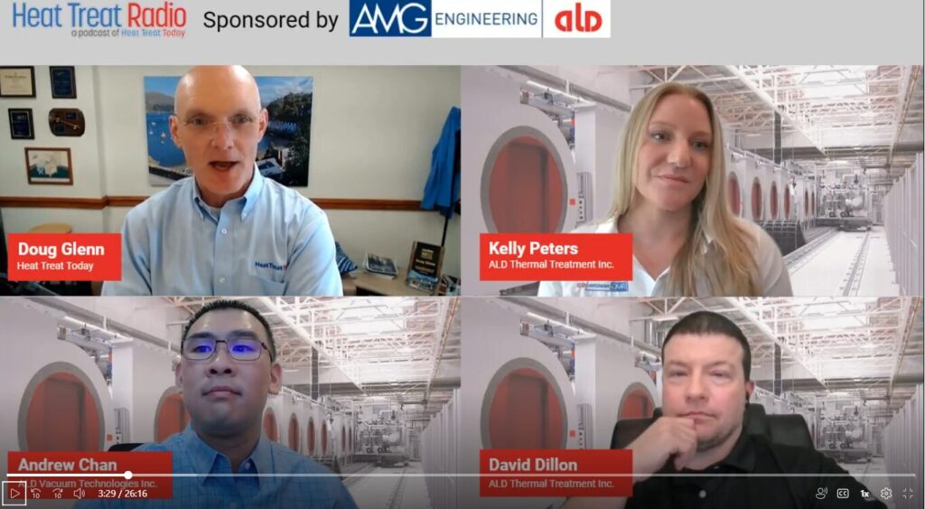
In this Heat Treat Radio episode, Doug Glenn talks with Andrew Chan, sales and applications engineer, ALD Vacuum Technologies North America Inc, Kelly Peters, vice president of operations, and David Dillon, maintenance manager for ALD Thermal Treatment Inc. 

Listen as guests share their experiences navigating the complex requirements, challenges, and organizational changes needed for Nadcap certification. Their journey discovering how multi-cell heat treatment furnaces can come into Nadcap compliance underscores the importance of technology, training, and continuous improvement.

Listeners will learn practical insights into achieving and maintaining Nadcap accreditation for advanced heat treatment processes. 

Below, you can watch the video, listen to the podcast by clicking on the audio play button, or read an edited transcript.


Introduction (01:13)  

Doug Glenn: In preparation for this episode, we discussed the situation that sparked our desire to engage in this conversation, which involved both ALD and some of your customers. We wanted to discuss people not knowing that a multi-cell heat treatment furnace could be Nadcap-certified. Can you tell us a little bit about that? 

Andrew Chan: ALD participates in all the major heat treatment trade shows, including the last two Furnaces North America events, and we noticed a lack of awareness that multi-cell heat treatment furnaces can be Nadcap certified. We found through interactions with visitors at our booth and conversations during the social hours that people really had it engraved in their minds that only single cell heat treatment equipment could be Nadcap certified. 

This was true until about five years ago with the newest revision of AMS2769D. Therefore, the real impetus is just to bring awareness to the industry that you’re now able to certify and use multi-cell heat treatment equipment for aerospace applications. With that, you get volume capacity, which historically has been associated with the automotive industry, both the OEMs and their suppliers, but we can bring that benefit to the aerospace market and lower heat treatment costs. 

Understanding Multi-Cell Furnace Systems (05:15)

Doug Glenn: What are multi-cell heat treatment furnaces, how are they designed, and how do they work? 

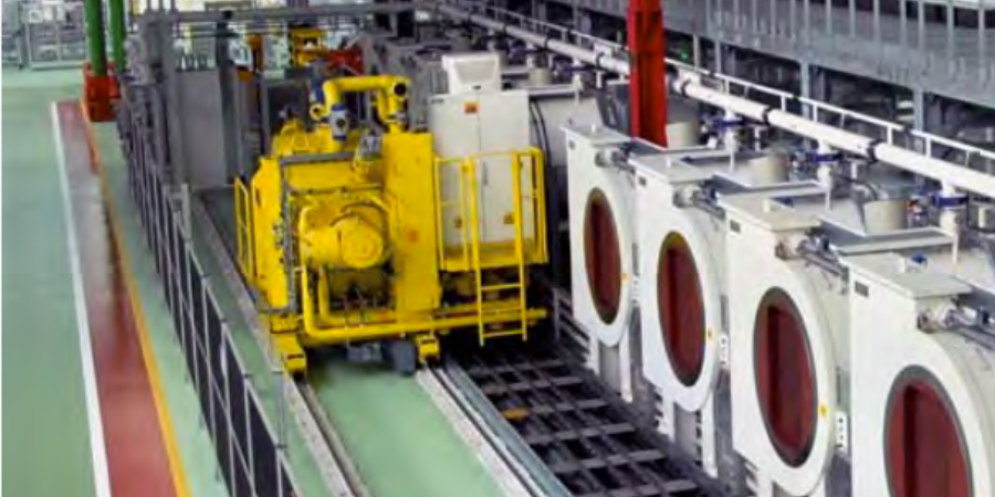
Andrew Chan: An example of a multi-cell furnace is our ModulTherm® or our SyncroTherm® furnace. As you can see in this image, these are individual vacuum chambers, which we call a treatment cell, and you can line up about fourteen of these in a row. Each one is dedicated to heat treating a single load.  

ALD’s ModulTherm® system, an example of multi-cell furnaces

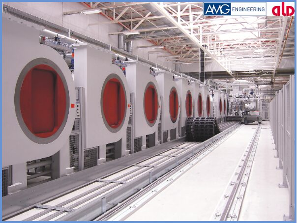
The treatment cell has its own insulation, heating elements, process, and gas; all of these are serviced by a single transfer car that you can see down at the end of the rail with the track. Then, our quenching cell is attached to that transfer car. We have this movable transfer car that loads and unloads the parts, and then we quench them immediately after pulling them out of each treatment cell. We can also do oil quenching, but the oil quench would just be a fixed tank — it would not be on this movable transfer car. 

Doug Glenn: Are you talking about a high pressure gas quench? 

Andrew Chan: Yes, this is a high pressure gas quench. Historically it’s been helium, but we can also do nitrogen, since helium costs have started to increase over the last couple decades.  

Doug Glenn: Is that transfer car under vacuum during the transfer? 

Andrew Chan: Yes, everything is done under vacuum. We transfer between the red doors, which are basically like isolation doors. When we pull the load out to quench it, it’s done very quickly, also under vacuum, we quench up to 20 bar. 

Doug Glenn: Is this your ModulTherm model? 

Andrew Chan: Yes, this image is of our ModulTherm. This second image is of our SyncroTherm model, which is like a mini ModulTherm.  

Nadcap certification is possible for multi-cell furnace systems, like the SyncroTherm®

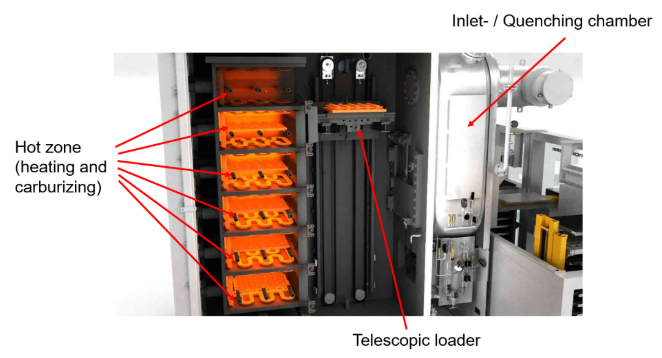
We describe this model like a pizza oven. We have multiple hot zones stacked on top of each other, and the footprint for the hot zone is approximately 500 x 600 millimeters. It is a smaller footprint than the ModulTherm model. Everything is under the same vacuum environment, and then similarly, we have a transfer — a telescopic loader that moves the load between the hot zone and the quench — and then a single quenching chamber, which also functions as the inlet and outlet for the load. 

What is Nadcap Certification? (8:25)

Doug Glenn: What is Nadcap certification? 

Kelly Peters: Nadcap certification is a comprehensive approach to aerospace and specifications. It covers maintenance, pyrometry, heat treater training, quality control, and even contract review. It focuses more on the process, not so much on the product, and it is audited by a third-party organization called PRI (Performance Review Institute).  

PRI will review your processes, supporting data, and entire management system. The accreditation process involves an internal audit completed by the organization with some corrective actions. Then, you can complete your initial audit with PRI.  

You must complete that internal audit first, and then once you go through the initial audit, you’ll be assigned a staff engineer. This person will review the findings from that initial audit, as well as your corrective actions and supporting data.  

If the staff engineer approves, you’ll move on to the next stage, which is actually going in front of an engineering team where they vote on whether you’ll be accredited.  

When it comes to heat treatment specifically for Nadcap, however, the audit really covers all of your AMS specifications, processes, relevant instrumentation, pyrometry, etc. 

Doug Glenn: Is the team of engineers that you mentioned internal or through PRI? 

Kelly Peters: They are through PRI. 

Doug Glenn: Is this certification and audit exclusively for the aerospace industry or is it applied to other industries? 

Kelly Peters: Nadcap is primarily for aerospace and defense. 

Process of ALD’s Nadcap Journey: Challenges and Timeline (10:25) 

Doug Glenn: Once you realized that you could Nadcap certify your equipment that Andrew and his team build, how did your Nadcap process go? Can you tell us how you got started and the timeline? 

Kelly Peters: The process was definitely very intimidating at first. In general, I would say the average time period in the industry is about 18 months of preparation before you find yourself going through the actual PRI audit.  

In our case, it took us about a year. We had a lot to do within that year. There were four months that it was all initial procedure revision. This step involves reviewing maintenance, production, and quality control processes and procedures to ensure they meet Nadcap requirements.  

You also have to go through commercial compliance. Therefore, you want to ensure that you’re meeting those specifications from the commercial side, specifically during contract review and processes.  

The largest portion of preparing was data collection and organizational changes, which took us about six to seven months to accomplish because you have to gather all the data necessary, implement changes, and then make those changes daily to ensure you’re actually in compliance.  

By the time you do your self-audit, you’re already zoning in on those items and initiating corrective actions to prepare for accreditation. About two months later, we scheduled our actual PRI audit and had them on-site. 

Doug Glenn: What do you mean by “organizational changes”?  

Kelly Peters: I’m implying changes to operational organization, for example, your management system.  

Overcoming Doubts and Technical Hurdles (14:28)

Doug Glenn: Dave, I assume you were involved with this process from the beginning.  

Dave Dillon: Yes, I was involved quite a bit. 

Doug Glenn: Were there any major potholes that occurred where you had to change a flat tire after you hit it? 

Dave Dillon: The biggest issue initially was how new the process was to us, which felt overwhelming — we didn’t know what to expect. As such, we had self-doubt. When we overcame that and started getting into the nuts and bolts of the process, the biggest challenge was reviewing our existing requirements from customers and our controlling standards, ensuring they met the Nadcap requirements. If they didn’t, we had to bring them up to that standard. 

Heat Treat Radio Episode #122 Andrew Chan, Kelly Peters, and David Dillon sharing their Nadcap experience

Doug Glenn: What was the most intimidating piece of the process or that stood out as a really difficult step?  

Kelly Peters: From my perspective, this goes right back to what Andrew said at the beginning of our discussion where there was a time when you didn’t believe you could get this accreditation for these ModulTherm systems. Because we were so ingrained in that thought process — that this was going to be such a hard, difficult challenge to get through — that we had to break through the barrier and realize that most of the challenge is in you, not so much in the system. The specifications are out there. Your job is to follow them. Your job is to implement them. It can be done. 

Dave Dillon: The biggest challenge for me was all the pyrometry requirements from AMS2750. We were doing it all on the fly, and we didn’t hire any additional staffing, so it was very challenging at first. Then eventually we determined that we needed to have our own pyrometry technician to make sure the testing was completed within the time allotted. 

Doug Glenn: When we discussed this before, you mentioned that you guys had engaged C3 Data to help you along the process. Can you tell us about that?  

Dave Dillon: Our pyrometry technician is an internal guy, but we started out by doing everything by hand — all of the paperwork, documentation, etc. Someone had recommended C3 Data to us, and after we reviewed their software, we realized it was a perfect process for us. The software allows us to eliminate human error. It gives you automatic checks, and then it provides a digital record for the auditors — great software. 

Doug Glenn: Kelly, what was your experience with C3 Data?  

Kelly Peters: Dave is definitely the one taking care of the groundwork, so I don’t have personal experience with C3 Data. However, I did notice that our internal findings were less driven by human error, as Dave was saying, because we were no longer using manual Excel spreadsheets and so didn’t have the ability to accidentally hit the wrong number. The data became more reliable. 

Doug Glenn: When it finally came time to do the actual PRI audit, how intimidating was that and how did it go? 

Dave Dillon: To be honest, it was terrifying. We were all nervous because it was all so new to us — it seemed very overwhelming. But the auditors, to their credit, are very good, and they help you through it. The most surprising part of the audit was that we were able to get accredited on our initial audit. 

Doug Glenn: I also understand you earned Nadcap merit. Can you tell us what that is? 

Kelly Peters: A unique aspect of the Nadcap accreditation is that once a company meets a certain criteria, that company can enter a merit program, which means you can go up to 24 months between your audits. Currently, Port Huron is at our 18-month mark, and that happened just after our last audit, so we’re very proud of that. 

Lessons Learned and Ongoing Improvements (19:46)

Doug Glenn: What are some lessons learned from this experience? 

“When it comes to lessons learned, ensuring that your new hires and your current staff are continually getting training, which is true with any type of process in manufacturing and business.”
Source: Canva Pro

Kelly Peters: When it comes to lessons learned, ensuring that your new hires and your current staff are continually getting training, which is true with any type of process in manufacturing and business. For pyrometry, we need to make sure we have a contingency. Dave knows it all, but if Dave wins the lottery tomorrow, we need someone to be able to step in and take over that process. Therefore, continual improvement, training, and reinforcing are critical because it’s all about maintaining a system, just like any other system that you have in place. I certainly would say that is not necessarily a challenge, but something to keep an eye on. 

Doug Glenn: Andrew, were you involved with the Nadcap approval process on the equipment side? 

Andrew Chan: I was not involved with the process for their specific equipment at Port Huron. However, from an equipment supplier perspective, it’s been challenging to help people understand that it’s possible to certify this equipment in the first place. 

We’re starting to see more interest in this now. Since we have this long history with our specific design, it doesn’t require many changes to make the equipment Nadcap certified. We have a comprehensive control system that does everything automatically, including data recording and being able to interrogate the data historically. With a couple tweaks to the equipment, like making sure the gas is dry and clean, and adjustments on the pyrometry side, it’s possible to be certification-ready. You just have to find someone that’s willing to take the equipment and go through the process that the equipment at Port Huron went through. 

Uses of Multi-Cell Furnaces (22:34)

Doug Glenn: What would the ideal company profile be that could benefit from knowing about this certification and having this equipment?  

Andrew Chan: This is dependent upon the parts that a company is producing. The ModulTherm is geared more towards larger pieces. The SyncroTherm is more of a competitive product and we have seen it used for aerospace before. The SyncroTherm is probably the right solution for most of our customers looking to get into this process.  

The ModulTherm is for high throughput, component heat treating. The automotive industry was one of the first industries to adopt it. In a way, they are more advanced than the aerospace industry, as they were able to adopt multi-cellular heat treatment into their industry. This is one of innovations that the aerospace industry is catching up on. 

We haven’t quite seen the demand on the ModulTherm side yet, but the SyncroTherm is probably the right furnace — something small that heat treats aerospace components with a small footprint and a very rapid turnaround time. 

Doug Glenn: Well, that’s great guys. Thanks very much. Kelly, Andrew, Dave, thanks for being with us. Hopefully it’s going to be helpful to some of our listeners, so appreciate you being here. 

About the Guests

Andrew Chan
sales and applications engineer
ALD Vacuum Technologies North America Inc

Andrew Chan has a background in Materials Science & Engineering and has been with ALD Vacuum Technologies North America Inc since 2020.  Andrew supports ALD’s vacuum heat treatment customers to specify new equipment builds and heat treatment process troubleshooting.  In addition, Andrew is responsible for EB-PVD technologies and assists with the vacuum metallurgy portfolio. 

Kelly Peters
vice president of operations
ALD Thermal Treatment Inc

Kelly Peters has been with ALD Thermal Treatment Inc since 2007, throughout her career at ALD she has held different job responsibilities primarily within R&D and Quality. Kelly Peters is a Heat Treat Today 40 under 40 Class of 2020 nominee.

David Dillon
maintenance manager
ALD Thermal Treatment Inc.

David Dillon has been with ALD Thermal Treatment Inc since 2006, working on equipment installations and maintenance locally in Port Huon. Dave now not only manages local maintenance activities but assists the parent company in equipment installations and services when needed


Heat Treat Radio #122: Lessons Learned from the Nadcap Certification Journey for Multi-Cell Furnaces  Read More »

How To Reduce Carbon Footprint During Heat Treatment

Given changing ecological and economic conditions, carbon neutrality is becoming more important, and the heat treatment shop is no exception. In the context of this article, the focus will be on how manufacturers — especially those with in-house heat treat — can save energy by evaluating heating systems, waste heat recovery, and the process gas aspects of the technology.

This article, written by Dr. Klaus Buchner, head of Research and Development at AICHELIN HOLDING GmbH, was released in Heat Treat Today April/May 2024 Sustainable Heat Treat Technologies print edition.


Introduction

Contact us with your Reader Feedback!

Uncertainties in energy supply and rising energy costs remind us of our dependence on fossil fuels. This underlines the need for a sustainable energy and climate policy, which is the central challenge of our time.

European policymakers have already taken the first steps towards a green energy revolution, and the heat treatment industry must also take responsibility. Many complementary measures, however, are needed that can be applied to new and existing thermal and thermochemical heat treatment lines.

Heat Treatment Processes and Plant Concepts

The heat treatment process itself is based on the requirements of the component parts, and especially on the steel grade used. If different concepts are technically comparable, it is primarily the economic aspect that is decisive, and not the carbon footprint — at least until now. Advances in materials technology and rising energy costs are calling for production processes to be modified.

Figure 1. Donut-shaped rotary-hearth furnace for carburizing with press quenching
Source: AICHELIN HOLDING GmbH

An example is the quenching and tempering of automotive forgings directly from the forging temperature without reheating, which has shown significant potential for energy and CO2 savings. Although the reduced toughness or measured impact energy of quenching and tempering from the forging temperature may be a drawback due to the coarser austenite grain size, this can be partially improved by Nb micro-alloyed steels and higher molybdenum (Mo) contents for more temper-resistant steels; it may also be necessary to use steels with modified alloying concepts when changing the process.1, 2 AFP steels (precipitation-hardening ferritic pearlitic steels) and bainitic air-hardening steels can also be interesting alternatives, since reheating (an energy-intensive intermediate step) is no longer necessary.

Similar considerations apply to direct hardening instead of single hardening in combination with carburizing processes because of the elimination of re-austenitizing. Distortion-sensitive parts often need to be quenched in fixtures due to the dimensional and shape changes caused by heat treatment. Heat treated parts are often carburized in multipurpose chamber furnaces or small continuous furnaces, cooled under inert gas, reheated in a rotary-hearth furnace, and quenched in a hardening press. In contrast, ring-shaped (aka donut-shaped) rotary-hearth furnaces allow carburizing and subsequent direct quenching in the quench press in a single treatment step. Figure 1 shows a typical ring-shaped rotary-hearth furnace concept for heat treating 500,000 gears per year/core hardness depth (CHD) group 1 mm.

Table 1. Saving potential due to increased process temperature for gas carburizing (pusher type furnace, 20MnCr5, CHD-group 1 mm)
Source: AICHELIN HOLDING GmbH

This ring-shaped rotary-hearth concept can save up to 25% of CO2 emissions, compared to an integral quench furnace line (consisting of four single-chamber furnaces, one rotary hearth furnace with quench press and two tempering furnaces as well as two Endothermic gas generators). Due to the reduced total process time (without reheating) and the optimized manpower, the total heat treatment costs can be reduced by 20–25%.

The high-temperature carburizing aspect should also be mentioned, although the term “high-temperature carburizing” is not fully accepted nor defined by international standards. As the temperature increases, the diffusion rate increases and the process time decreases. As shown in Table 1, the additional energy consumption is less than the increase in throughput that can be achieved. Therefore, the relative energy consumption per kg of material to be heat treated decreases as the process temperature increases.

There are three key issues to consider when running a high-temperature carburizing process:

  • Steel grade: Fine-grain stabilized steels are required for direct hardening at temperatures of 1832°F (1000°C). Microalloying of Nb, Ti, and N as well as a favorable microstructure of the steels reduce the growth of austenite grains and allow carburizing temperatures up to 1922°F (1050°C) for several hours.
  • Furnace design: In addition to the general aspects of the optimized furnace technology (e.g. heating capacity, insulation materials, and feedthroughs), failure-critical components must be considered separately in terms of wear and tear, whereby condition monitoring tools can support maintenance in this area.
  • Distortion: This is always a concern, especially in the case of upright loading of thin-walled gear sections. As such, numerical simulations and/or experimental testing should be performed at the beginning to estimate possible changes in distortion and to take measures if necessary.
Figure 2. Recuperative burner with SCR system for NOx reduction Source: AICHELIN HOLDING GmbH

Heating System

Based on an energy balance that considers total energy losses, and preferably also temperature levels, it can be seen that the heating system plays a significant role. In addition to the obvious flue gas loss in the case of a gas-fired thermal processing furnace, the actual carbon footprint must be critically examined.

In the case of natural gas, the upstream process chain is often neglected in terms of CO2 emissions, but the differences in gas processing (which are directly linked to the reservoirs) and in gas transportation can be a significant factor.3 However, the analysis of energy resources in the case of electric heating systems is much more important. This results in specific CO2 emissions between 30–60 gCO2/kWh (renewable-based electricity mix) and 500–700 gCO2/kWh (coal-based electricity mix). Therefore, a general comparison between natural gas heating and electric heating systems in terms of carbon footprint is often misleading.

Figure 3. Comparison of specific CO2 emissions Source: AICHELIN HOLDING GmbH

Nevertheless, in the case of gas heating, the aspect of combustion air preheating should be emphasized, as it has a significant influence on combustion efficiency. The technical possibilities in this area are well known and include both systems with central air preheating and decentralized concepts, where the individual burner and the heat exchanger form a single unit. Recuperator burners are often used in combination with radiant heating tubes (indirect heating) in the field of thermochemical heat treatment. With respect to oxy-fuel burners, it should also be noted that the formation of thermal NOx increases with increasing combustion temperature and temperature peaks. To avoid exceeding NOx emissions, staged combustion and so-called “flameless combustion” — characterized by special internal recirculation — and selective catalytic reduction (SCR) can be used. The latter secondary measure, together with selective non-catalytic reduction (SNCR), has been state-of-the-art in power plant design for decades and has become widely known because of its use in the automotive sector. This system can also be adapted to single burners (Figure 2). In this way, NOx emissions can be reduced to 30 mg/Nm3 (5% reference oxygen), depending on the injection of aqueous urea solution, as long as the exhaust gas temperature is in the range of 392/482°F (200/250°C) to 752/842°F (400/450°C).4

Whether electric heating is a viable alternative depends on both the local electricity mix and the design of the heat treatment plant, which may limit the space available for the required heating capacity. In addition to these technical aspects, the security of supply and the energy cost trends must also be considered. Both of these factors are significantly influenced by the political environment. Figure 3 shows an example of the specific carbon footprint per kg of heat treated material with the significant losses based on the example of an integral quench furnace concept in the double-chamber and single-chamber variants electrically heated (E) and gas heated (G). The electric heating is based on a fossil fuel mix of 485 gCO2/kWh. Once again, it is clear that a general statement regarding CO2 emissions is not possible; rather, the boundary conditions must be critically examined.

Waste Heat Recovery — Strengths and Weaknesses of the System

Although improvements in the energy efficiency of heat treatment processes, equipment designs, and components are the basis for rational energy use, from an environmental perspective it is important to consider the total carbon footprint. An energy flow analysis of the heat treatment plant, including all auxiliary equipment, shows the total energy consumption and thus the potential savings. Quite often the temperature levels and time dependencies involved preclude direct heat recovery within the furnace system at an economically justifiable investment cost. In this case, cross-plant solutions should be sought, which require interdepartmental action but offer bigger potential.

In addition to the classic methods of direct waste heat utilization using heat exchangers, also in combination with heat accumulators, indirect heat utilization can lower or raise the temperature level of the waste heat by using additional energy (chiller or heat pump) or convert the waste heat into electricity. The overview in Table 2 provides reference values in terms of performance class and temperature level for the alternative technologies listed.

Process Gas for Case Hardening

Case hardening — a thermochemical process consisting of carburizing and subsequent hardening — gives workpieces different microstructures across the cross-section, the key factor being high hardness/strength in the edge region. A distinction can be made between low pressure carburizing in vacuum systems and atmospheric carburizing at normal pressure. Both processes have different advantages and disadvantages, with atmospheric heat treatment being the dominant process.

Table 2. Overview of alternative waste heat applications5, 6
Source: AICHELIN HOLDING GmbH

In terms of carbon footprint, atmospheric heat treatment has a weakness due to process gas consumption. To counteract this, the following aspects have to be considered: thermal utilization of the process gas — indirectly by means of heat exchangers or directly by lean gas combustion (downcycling); reprocessing of the process gas (recycling); reduction of the process gas consumption by optimized process control; and use of CO2-neutral media (avoidance). This article focuses on avoidance by optimizing process gas consumption and using of CO2-neutral media.

Typically, heat treatment operations are still run with constant process gas quantities based on the most unfavorable conditions. Based on the studies of Wyss, however, process control systems offer the possibility to adapt the actual process gas savings to the actual demand.7 In a study of an industrial chamber furnace, a 40% process gas savings was demonstrated for a selected carburizing process. In this heat treatment process with a case hardness depth of 2 mm, the previously used constant gas flow rate of 18 m3/h was reduced to 16 m3/h for the first process phase and further reduced to 8 m3/h after 3 hours. Figure 4 shows the analysis of the gas atmosphere, where an increase in the H2 concentration could be detected due to the reduction of the gas quantities. With respect to the heat treatment result, no significant difference in the carburizing result was observed despite this significant reduction in process gas volume (and the associated reduction in CO2 emissions). The differences in the carbon profiles are within the expected measurement uncertainty.

Figure 4. CO and H2/CO concentration at various process gas volumes Source: AICHELIN HOLDING GmbH

The carbon footprint of the process gas, however, must be fundamentally questioned. In the field of atmospheric gas carburizing, process gases based on Endothermic gas (which is produced by the catalytic reaction of natural gas or propane with air at 1832–1922°F/1000–1050°C) and nitrogen/methanol and methanol only systems have established themselves on a large scale. Methanol production is still mostly based on fossil fuels (natural gas or coal), the latter being used mainly in China. Although alternative CO2-neutral processes for partial substitution of natural gas — keywords being “power to gas” (P2G) or “synthetic natural gas” (SNG) — have already been successfully demonstrated in pilot plants, there are no signs of industrial penetration. Nevertheless, there is a definite industrial scale in the area of bio-methanol synthesis, though so far, purely economic considerations speak against it, as CO2 emissions are still not taken into account.

The question of the use of bio-methanol in atmospheric gas carburizing has been investigated in tests on an integral quench furnace system. A standard load of component parts with a CHD of 0.4 mm was used as a reference. Subsequently, the heat treatment process was repeated with identical process parameters using bio-methanol instead of the usual methanol based on fossil fuels. Both the laboratory analyses of the methanol samples and the measurements of the process gas atmosphere during the heat treatment process, as well as the evaluation of the sample parts with regard to the carbon profile during the carburizing process, showed no significant difference between the different types of methanol. Although this does not represent long-term experience, these results underscore the fundamental possibility of media substitution and the use of CO2-neutral methanol.

Conclusion

Facing the challenges of global warming — intensified by the economic pressure of rising energy costs — this article demonstrates the energy-saving potential in the field of heat treatment. In addition to already established solutions, the possibilities of the smart factory concept must also be integrated in this industrial sector. Thus, heat treatment comes a significant step closer to the goal of a CO2-neutral process in terms of Scopes 1, 2, and 3 regarding emissions under the given boundary conditions.

References

[1] Karl-Wilhelm Wegner, “Werkstoffentwicklung für Schmiedeteile im Automobilbau,” ATZ Automobiltechnische Zeitschrift 100, (1998): 918–927, https://doi.org/10.1007/BF03223434.
[2] Wolfgang Bleck and Elvira Moeller, Steel Handbook (Carl Hanser Verlag GmbH & Co. KG, 2018).
[3] Wolfgang Köppel, Charlotte Degünther, and Jakob Wachsmuth, “Assessment of upstream emissions from natural gas production in Germany,” Federal Environment Agency (January 2018): https://www.umweltbundesamt.de/publikationen/bewertung-der-vorkettenemissionen-beider.
[4] Klaus Buchner and Johanes Uhlig, “Discussion on Energy Saving and Emission Reduction Technology of Heat Treatment Equipment,” Berg Huettenmaenn Monatsh 168 (2021): 109–113, https://doi.org/10.1007/s00501-023-01328-5.
[5] Technologie der Abwärmenutzung. Sächsische Energieagentur – SAENA GmbH, 2. Auflage, 2016.
[6] Brandstätter, R.: Industrielle Abwärmenutzung. Amt der OÖ Landesregierung, 1. Auflage, 109–113, https://doi.org/10.1007/s00501 02301328-5.
[7] U. Wyss, “Verbrauch an Trägergas bei der Gasaufkohlung,” HTM Journal of Heat Treatment Materials 38, no. 1 (1983): 4-9, https://doi.org/10.1515/htm-1983-380102.

About the Author

Dr. Klaus Buchner Head of Research and Development AICHELIN HOLDING GmbH

Klaus Buchner holds a doctorate and is the head of research and development at AICHELIN HOLDING GmbH. This article is based on Klaus Buchner’s article, “Reduktion des CO2-Fußabdrucks in der Wärmebehandlung” in Prozesswärme 01-2023 (pp. 42-45).

For more information: Klaus at klaus.buchner@aichelin.com.

This article content is used with the permission of heat processing, which published this article in 2023.

Find Heat Treating Products And Services When You Search On Heat Treat Buyers Guide.Com

How To Reduce Carbon Footprint During Heat Treatment Read More »

All About the Quench and Keeping Cool: Thru-process Temp Monitoring and Gas Carburizing

The future of heat treating requires new manufacturing solutions like robotics that can work with modular design. Yet so also does temperature monitoring need to be seamless to know how effectively your components are being heat treated — especially through being quenched. In this Technical Tuesday, learn more about temperature monitoring through the quench process.

Gas Carburization

Contact us with your Reader Feedback!

Carburizing has rapidly become one of the most critical heat treatment processes employed in the manufacture of automotive components. Also referred to as case hardening, it provides necessary surface resistance to wear, while maintaining toughness and core strength essential for hardworking automotive parts.

Figure 1. Typical carburizing heat treat temperature profile showing the critical temperature/time steps: (i) carburization, (ii) quench, and (iii) temper. (Source: PhoenixTM)

The carburizing process is achieved by heat treating the product in a carbon rich environment (Figure 1), typically at a temperature of 1562°F–1922°F (850°C–1050°C). The temperature and process time significantly influence the depth of carbon diffusion and other related surface characteristics. Critical to the process is a rapid quenching of the product following the diffusion in which the temperature is rapidly decreased to generate the microstructure, giving the enhanced surface hardness while maintaining a soft and tough product core.

The outer surface becomes hard via the transformation from austenite to martensite while the core remains soft and tough as a ferritic and/or pearlitic microstructure. Normally, carburized microstructures following quench are further tempered at temperatures of about 356°F (180°C) to transform some of the brittle martensite into tempered martensite to enhance ductility and grindability.

Critical Process Temperature Control

As discussed, the success of carburization is dependent on accurate, repeatable control of the product temperature and time at that temperature through the complete heat treatment process. Important to the whole operation is the quench, in which the rate of cooling (product temperature change) is critical to achieve the desired changes in microstructure, creating the surface hardness. It is interesting that the success of the whole heat treat process can rest on a process step which is so short (minutes), in terms of the complete heat teat process (hours). Getting the quench correct is not only essential to achieve the desired metal microstructure, but also to ensure that the physical dimensions and shape of the product are maintained (no distortion/warping) and issues such as quench cracking are eliminated.

Obviously, as the quench is so critical to the whole heat treat process, the correct quench selection needs to be made to achieve the optimum properties with acceptable levels of dimensional change. Many different quenchants can be applied with differing quenching performances. The rate of heat transfer (quench rate) of quench media in general follows this order from slowest to quickest: air, salt, polymer, oil, caustic, and water.

Technology Challenges for Temperature Monitoring

When considering carburization from an industry standpoint, furnace heat treat technology generally falls into one of two camps, embracing either air quench (low pressure carburization) or oil quench (sealed gas carburization/LPC with integral or vacuum oil quench). Although each achieves the same end goal, the heat treat mechanisms and technologies employed are very different, as are the temperature monitoring challenges.

To achieve the desired carburized product, it is necessary to control and hence monitor the product temperature through the three phases of the heat treat process. Conventionally, product temperature monitoring would be attempted using the traditional trailing thermocouple method. For many modern heat treat processes including carburization, the trailing thermocouple method is difficult and often practically impossible.1 The movement of the product or product basket from stage to stage, often from one independent sealed chamber to another (lateral or vertical movement), makes the monitoring of the complete process a significant challenge.

With the industry driving toward fully automated manufacturing, furnace manufacturers are now offering the complete package with full robotic product loading that includes shuttle transfer systems and modular heat treat phases to process both complete product baskets and single piece operations. Although trailing thermocouples may allow individual stages in the process to be measured, they cannot provide monitoring of the complete heat treat journey. Testing is therefore not under true normal production conditions, and therefore is not an accurate record of what happens in normal day to day operation.

Figure 2 shows schematic diagrams of two typical carburizing furnace configurations that would not be possible to monitor using trailing thermocouples. The first shows a modular batch furnace system where the product basket is transferred between each static heat treat operation (preheat, carburizing furnace, cooling station, quench, quench wash, temper furnace) via a charge transfer cart. The second shows the same heat treat operation but performed in a continuous indexed pusher furnace configuration where the product basket moves sequentially through each heat treat operation in a semi-continuous flow.

Figure 2.1. Modular batch furnace system (Source: PhoenixTM)
Figure 2.2. Continuous pusher furnace schematic (Source: PhoenixTM)

Thru-process temperature monitoring as a technique overcomes such technical restrictions. The data logger is protected by a specially designed thermal barrier, therefore, can travel with the product through each stage of the process measuring the product/process temperature with short, localized thermocouples that will not hinder travel. The careful design and construction of the monitoring system is important to address the specific challenges that different heat treat technology brings including modular batch and continuous pusher furnace designs (Figure 2).2

The following section will focus specifically on monitoring challenges of the sealed gas carburizing process with integral oil quench. Technical challenges of the alternative low pressure carburizing technology with high pressure gas quench have previously been discussed in an earlier publication.3

Monitoring Challenges of Sealed Gas Carburization — Oil Quench

Figure 3. “Thru-process” temperature monitoring system for use in a sealed carburizing furnace with integral oil quench — (3.1) Monitoring system entering furnace with thermocouple fixed to automotive gears, product test pieces (3.2) System exiting oil quench tank (3.3) System inserted into wash tank with product basket (Source: PhoenixTM)

Presently, the most common traditional method of gas carburizing for automotive steels is often referred to as sealed gas carburizing. In this method, the parts are surrounded by an endothermic gas atmosphere. Carbon is generated by the Boudouard reaction during the carburization process, typically at 1562°F–1832°F (850°C –1000°C). Despite the dramatic appearance of a sealed gas carburizing furnace, with its characteristic belching flames (Figure 3), from a monitoring perspective, the most challenging aspect of the process is not the heating, but the oil quench cooling. For such furnace technology, the historic limitation of “thru-process” temperature profiling has been the need to bypass the oil quench and wash stations, missing a critical process step from the monitoring operation. Obviously, passing a conventional hot barrier through an oil quench creates potential risk of both system damage from oil ingress and barrier distortion, as well as general process safety. However, the need to bypass the quench in certain furnace configurations by removing the hot system from the confined furnace space could create significant operational challenges, from an access and safety perspective.

Monitoring of the quench is important as ageing of the oil results in decomposition (thermal cracking), oxidation, and contamination (e.g. water) of the oil, all of which degrade the viscosity, heat transfer characteristics, and quench efficiency. Control of physical oil temperature and agitation rates is also key to oil quench performance. Quench monitoring allows economic oil replacement schedules to be set, without risk to process performance and product quality.

Figure 4. “Thru-process” temperature monitoring system oil quench compatible thermal barrier design: (1) Robust outer structural frame keeping insulation and inner barrier secure; (2) Internal thermal barrier — completely sealed with integral microporous insulation protecting data logger; (3) Mineral insulated thermocouples sealed in internal thermal barrier with oil tight compression fitting; (4) Multi-channel high temperature data logger; and (5) Sacrificial insulation blocks replaced after each run. (Source: PhoenixTM)

To address the process challenges, a unique thermal barrier design has been developed that both protects the data logger in the furnace (typically three hours at 1697°F/925°C) and also protects during transfer through the oil quench (typically 15 mins) and final wash station (Figure 3). The key to the barrier design is the encasement of a sealed inner barrier with its own thermal protection with blocks of high-grade sacrificial insulation contained in a robust outer structural frame (Figure 4).

Quench Cooling Phases

Monitoring the oil quench in carburization gives the operator a unique insight into the product’s specific cooling characteristics, which can be critical to allow optimal product loading and process understanding and optimization. From a scientific perspective, the quench temperature profile trace, although only a couple of minutes in duration, is complex and unique. From a zoomed in quench trace (Figure 5) taken from a complete carburizing profile run, the three unique heat transfer phases making up the oil quench cool curve can be clearly identified:

Figure 5. Oil quench temperature profile for different locations on an automotive gear test piece shows the three distinct heat transfer phases: (1) film boiling “vapor blanket”, (2) nucleate boiling, and (3) convective heat transfer. (Source: PhoenixTM)
  1. Film boiling “vapor Blanket”: The oil quenchant creates a layer of vapor (Leidenfrost phenomenon) covering the metal surface. Cooling in this stage is a function of conduction through the vapor envelope. Slow cool rate since the vapor blanket acts as an insulator.
  2. Nucleate boiling: As the part cools, the vapor blanket collapses and nucleate boiling results. Heat transfer is fastest during this phase, typically two orders of magnitude higher than in film boiling.
  3. Convective heat transfer: When the part temperature drops below the oil boiling point. the cooling rate slows significantly. The cooling rate is exponentially dependent on the oil’s viscosity.

From a heat treat perspective, the quench step relative to the whole process (hours) is quick (seconds), but it is probably the most critical to the performance of the metallurgical phase transitions and achieving the desired core microstructure of the product without risk of distortion. By being able to monitor the quench step, the process can be validated for different products with differing size, form, and thermal mass. As shown in Figure 6, the quench curve profile over the three heat transfer phases is very different for two different automotive gear sizes.

Figure 6. Oil quench temperature profile for different automotive gear sizes (20MnCr5 case hardening steel) with different thermal masses: Passenger Car Gear (2.2 lbs) and Commercial Vehicle Gear (17.6 lbs) (Source: PhoenixTM)

Summary

As discussed in this article, one of the key process performance factors associated with gas carburization is the control and monitoring of the product quench step. Employing an oil quench, the measurement of such operation is now very feasible as part of heat treat monitoring. Innovations in thru-process temperature profiling technology offer specific system designs to meet the respective application challenges.

References

[1] Dr. Steve Offley, “The light at the end of the tunnel – Monitoring Mesh Belt Furnaces,” Heat Treat Today, February 2022, https://www.heattreattoday.com/processes/brazing/brazing-technical-content/the-light-at-the-end-of-the-tunnel-monitoring-mesh-belt-furnaces/.

[2] Michael Mouilleseaux, “Heat Treat Radio #102: Lunch & Learn, Batch IQ Vs. Continuous Pusher, Part 1,” interviewed by Doug Glenn, Heat Treat Radio, October 26, 2023, audio, https://www.heattreattoday.com/media-category/heat-treat-radio/heat-treat-radio-102-102-lunch-learn-batch-iq-vs-continuous-pusher-part-1/.

[3] Dr. Steve Offley, “Discover the DNA of Automotive Heat Treat: Thru-process Temperature Monitoring,” Heat Treat Today, August 2023, https://www.heattreattoday.com/discover-the-dna-of-automotive-heat-treat-thru-process-temperature-monitoring/.

About the Author

Dr Steve Offley (“Dr O”), Product Marketing Manager, PhoenixTM

Dr. Steve Offley, “Dr. O,” has been the product marketing manager at PhoenixTM for the last five years after a career of over 25 years in temperature monitoring focusing on the heat treatment, paint, and general manufacturing industries. A key aspect of his role is the product management of the innovative PhoenixTM range of thru-process temperature and optical profiling and TUS monitoring system solutions.

For more information: Contact Steve at Steve.Offley@phoenixtm.com.

Find Heat Treating Products And Services When You Search On Heat Treat Buyers Guide.Com

All About the Quench and Keeping Cool: Thru-process Temp Monitoring and Gas Carburizing Read More »

ThermTech Expands Heat-Treat Furnace Line to Support Oil & Gas Industry

ThermTech, based in Waukesha, WI, recently added a batch integral quench furnace to their atmosphere heat-treat furnace line. The expansion is in response to an increase in demand for carburizing, carbonitriding, and neutral hardening services from their oil & gas and heavy equipment industry clients.  ThermTech acquired the ATLAS furnace from Ipsen USA, adding to existing atmosphere furnace and ancillary equipment already in operation.

ThermTech Expands Heat-Treat Furnace Line to Support Oil & Gas Industry Read More »

Carbon Sensor Troubleshooting

Jim Oakes, Super Systems, Carbon Sensor Troubleshooting, Stephen Thompson

by Stephen Thompson – President – Super Systems, Inc.

There are several key components in all atmosphere control systems. When a difficulty arises, it is important to identify the cause with minimum effort and expended time. The procedure that follows is designed to aid in that process.

INTRODUCTION

The starting point for any troubleshooting procedure is to properly identify the symptom that necessitates it. The cause of the symptom can often be elicited by answering some preliminary questions. Is this a startup problem, or has the system been operating under control? If this is a startup problem, it is necessary to establish that all system components have been properly connected and configured for the application. If the system has been operating properly and there has been either a gradual or sudden change in the control performance, it may conceivably be a problem with the probe. In order to establish the correct performance of the carbon sensor, resist the temptation to remove the sensor from the furnace. All of the tests outlined here must be done while the sensor is located in the furnace, at temperature, and exposed to a reducing atmosphere. This procedure can be performed on the SSi Gold Probe and on most other manufacturers’ sensors. We strongly recommend that you call us at 800-666-4330 before you remove the probe.

NOTE: IF YOU HAVE ALREADY REPLACED THE PROBE AND THE PROBLEM PERSISTS…..THE PROBE MAY NOT BE THE PROBLEM!

PROCEDURE

Does a shim stock analysis, a 3-gas analysis (SSi PGA3000) or a dew point analysis (SSi DP2000) verify the indicated value from the probe? If the values are close to the same, the problem is not likely the Gold Probe. If the values are not similar, continue with the following steps:

  1. Verify that both mV and t/c cables between the sensor and the controller are clean and connected firmly to the Gold Probe and controller terminals. Verify polarity.
  2. Verify that the reference air supply is connected to the reference air fitting. This will be the fitting closest to you when you face the probe. It has been found that on occasion the reference air has been connected in error to the burn off fitting, causing low readings.
  3. Check that the reference air is flowing. Disconnect the air supply at the probe and submerge it in a cup of water. Bubbles verify the flow.
  4. Verify that no air is flowing into the burn off fitting by submerging the burn off tubing in a cup of water. (Flow can occur if the burn off air pump is subject to external vibration.)
  5. Leak test- this test can detect a cracked or broken substrate in your Gold Probe. Verify that reference air is flowing at 0.5 to 2.0 scfh. Turn off the reference air for one minute and read the Gold Probe output millivolts. Turn the reference air back on and note the change in mV. It should not display more than a 5 mV increase.
  6. Is the controller COF set to the proper value? This factor is referred to by other descriptions such as Process Factor, Furnace Factor, CO Factor, Circulation Factor, Calibration Factor, etc. The factor may require adjustment to eliminate any offset or discrepancy between the indicated carbon potential and the actual achieved result in the work pieces or shim stock.
  7. Do the sensor temperature and MV output as measured by an independent digital calibrator agree with the indicated values on the controller with one sensor and one t/c lead disconnected? If not, there is most likely a controller calibration problem or a cable problem.
  8. Does the Gold Probe mV signal return to within 1mV of it’s original value in 1 minute as measured by a digital VOM after it has been shorted for 5 seconds? If it does not, go to step 10.
  9. Probe impedance (resistance) test-this is one of several electrical tests that determine the electrical integrity and reliability of the Gold Probe. Some contemporary controllers can perform it. If yours does not, conduct this simple test: at process temperature, disconnect the controller cable at the Gold Probe mV output and measure the mV value with a VOM. Then shunt the signal with a 100 kilohm resistor. After 10 seconds, read the new mV value, divide the original value by the new value, subtract 1 from the result and multiply by the value of the shunt resistor (=100K). The calculated value is the sensor resistance in kilohms, which should be less than 25 kilohms.
  10. If the problem is not corrected by probe and/or furnace burnout as described in the Gold Probe Manual and your system manual, and the problem is a faulty probe, contact SSi at (800)666-4330 and describe your problem to our technician. You may then request a Returned Material Authorization for repair or replacement of your Gold Probe.
  11. WARNING- even though you suspect a faulty sensor, DO NOT remove your Gold Probe from a hot furnace at a rate faster than 2 inches per minute. Cool the sensor on an insulating medium to avoid thermal shock. This will prevent damage that is expensive to repair.

Author information:
Stephen Thompson
Super Systems Inc.
7205 Edington Drive, Cincinnati,  OH 45249
Phone: 513-772-0060
Fax: 513-772-9466
www.supersystems.com

Carbon Sensor Troubleshooting Read More »

Majority of Heat Treatment Done In-House at SKF — New Equipment Purchased

Ipsen recently installed both atmosphere and vacuum heat-treating systems at SKF’s state-of-the-art manufacturing facility in St. Louis, Missouri. With the relocation of their existing facility to a new location, SKF continues to focus on enhancing the quality, efficiency and overall effectiveness of their heat-treating equipment. Among this new Ipsen equipment was a complete ATLAS atmosphere heat-treating system, including two ATLAS integral quench batch furnaces and ancillary equipment – washer, temper, endo generator, loader/unloader and a feed-in/feed-out station. SKF also purchased a TITAN® vacuum heat-treating system to round out their production capabilities.

Heat-treating is considered a core competency at SKF, and this new equipment will allow them to bring the majority of heat treatment in-house and efficiently handle the increase they’ve seen in production demands and volume of parts. Reflecting on the equipment purchased and what appealed to SKF, Bryan Stanford said, “Initially, I would say it was the general purposefulness of these Ipsen products that appealed to us. We run a very large variety of parts and batch quantities here. A custom solution designed to run tens of thousands of the same parts was not going to work for us. We wanted a low-cost, off-the-shelf-type solution that would allow us the flexibility we required – which is what the ATLAS and TITAN delivered. Now after having performed some pre-training, I would say what stands out the most is the ease of use and control of the equipment.”

The ATLAS batch furnaces feature a 24″ W x 36″ D x 30″ H (610 mm x 910 mm x 760 mm) load size with an 1,100-pound (500 kg) load capacity. They also operate at temperatures of 1,400 °F to 1,800 °F (750 °C to 980 °C) and have a quench oil capacity of 1,030 gallons (3,900 L). The TITAN vacuum furnace features an 18″ W x 24″ D x 18″ H (455 mm x 610 mm x 455 mm) load size with a 1,000-pound (454 kg) load capacity. It operates at temperatures of 1,000 °F to 2,400 °F (538 °C to 1,316 °C). Overall, this Ipsen equipment will be used for carburizing, carbonitriding, brazing and annealing and will process a wide variety of parts that support SKF’s Lubrication Business Unit.

Majority of Heat Treatment Done In-House at SKF — New Equipment Purchased Read More »

Heat Treatment and Wicked Problems

BOTW-50w  Source:  Linked In – Peter Sherwin

“I am wide awake on a late night flight from Kolkata to Delhi (India) so I pick up my phone to continue reading “Design to Grow – How Coca Cola learned to combine scale and agility.” I happened on the chapter discussing wicked problems – with sustainability of water use being one of Coke’s wicked problem (basically a wicked problem is one that is ill-defined, has many uncontrollable variables and has no so-called right or optimal solutions).

Having spent the week traveling around India and visiting customers with typical heat treat problems and seeing and hearing about and presenting the latest technology solutions in Heat Treat – I have come to the conclusion Heat Treatment is itself a wicked problem.”

Read More:  Peter Sherwin – Eurotherm – Linked IN

Heat Treatment and Wicked Problems Read More »

Enhancing Energy Efficiency of Thermochemical Vacuum-Processes and Systems

BOTW-50w  Source:  Heat Processing

“The energy optimization of thermoprocessing equipment is of great ecological and economical importance. Thermoprocessing equipment consumes up to 40 % of the energy used in industrial applications in Germany. Therefore it is necessary to increase the energy efficiency of thermoprocessing equipment in order to meet the EU’s targets to reduce greenhouse gas emissions. In order to exploit the potential for energy savings, it is essential to analyze and optimize processes and plants as well as operating methods of electrically heated vacuum plants used in large scale production. For processes, the accelerated heating of charges through convection and higher process temperatures in diffusion-controlled thermochemical processes are a possibility. Modular vacuum systems prove to be very energy-efficient because they adapt to the changing production requirements step-by-step. An optimized insulation structure considerably reduces thermal losses. Energy management systems installed in the plant-control optimally manage the energy used for start-up and shutdown of the plants while preventing energy peak loads. The use of new CFC-fixtures also contributes to reduce the energy demand.”

Enhancing Energy Efficiency of Thermochemical Vacuum-Processes and Systems Read More »