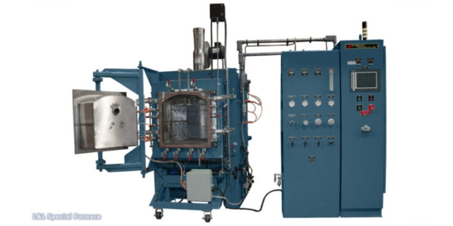
A leading manufacturer of aerospace components in the Midwestern U.S. has received one of two furnaces, which will be part of a CMC manufacturing facility providing lightweight aerospace components to commercial and military aerospace applications.
These two model XLC3348 furnaces were delivered by L&L Special Furnace. The nano threads in the CMC process are coated with proprietary resins which need to be completely removed from the substructure using heat. It is also vital that there is no oxygen present during the process as this will significantly weaken the part structure.
The model XLC3348 has a work zone of 23” wide by 23” high by 36” deep. It has a single zone of control with a temperature gradient of ±14°C/±25.2°F at temperatures between 1202°F/650°C and 1832°F/1,000°C using six zones of temperature control with biasing to balance any gradients. Constructed of low-mass insulating firebrick, which enables quicker cooldown times, the furnace also features a venturi cooling blower.
The parts are heated to a set temperature in a retort chamber that is pressurized with nitrogen. The byproducts of the outgassing part are directed by pressure and flow out of the rear of the furnace, and then heated in a vacuum furnace to temperatures in excess of 2300°F/ 1,260°C, resulting in a super-strong component that is lighter than titanium.
Find heat treating products and services when you search on Heat Treat Buyers Guide.com
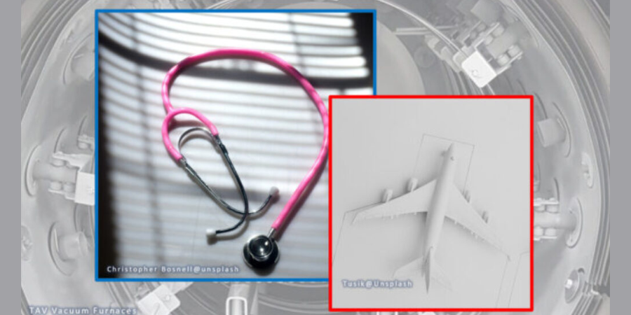
Those familiar with vacuum heat treatments are surely acquainted with the vacuum heat treatment of titanium and how such furnaces create the ideal environment for titanium's heat treatment. However, not all titanium and its alloys are created equal. Enter the beta titanium alloy.
In this best of the web article from TAV Vacuum Furnaces, discover the potential applications for beta titanium alloys, as well as the effects that various vacuum heat treatments can have on the mechanical properties of the alloy. Additive manufacturing (AM) technologies, specifically laser powder bed fusion, are gaining increased interest in the treatment of beta titanium alloys, due to their efficiency and their cost-cutting potential. Learn more about the chemistry and applications of this unique material below.
An excerpt:
Beta titanium alloys have an unique combination of desirable properties: their high specific strengths, creep resistance, oxidation and corrosion resistance, excellent temperature resistance up to 600°C and hardenability, make them very attractive for aerospace applications. On the other hand, the excellent biocompatibility and low elastic modulus, closer to that of human bone compared to other alloys, make Ti beta alloys an excellent material for biomedical applications.
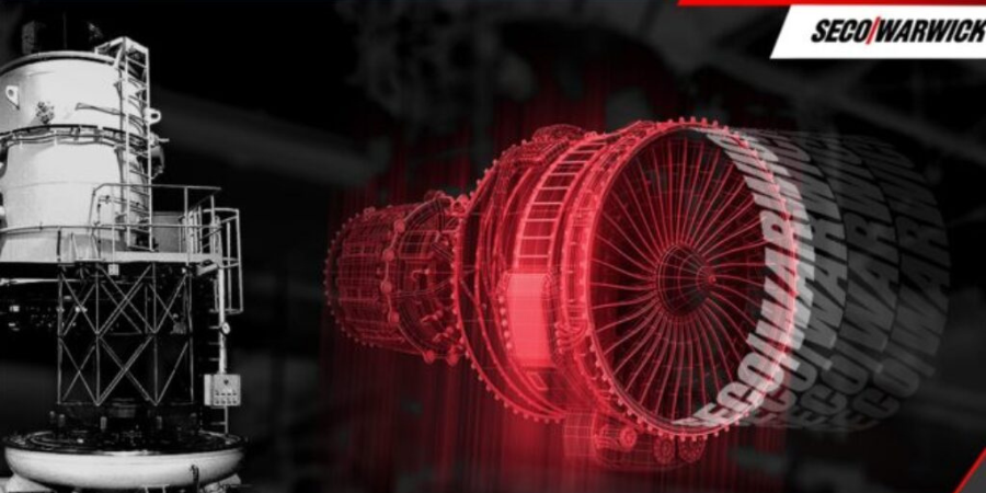
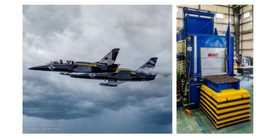
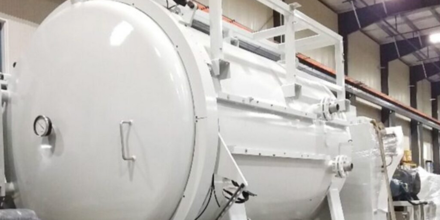
A vertical vacuum furnace is heading to a company that provides repair and maintenance services for jet engines. The system has been designed to carry out clean brazing processes in high vacuum, ensuring protection of the treated part surfaces. The solution will be used to process jet engine components.
The system will improve production processes and significantly increase the commercial heat treater’s efficiency. "The vertical vacuum furnace is the answer to the challenges of annealing and brazing larger aviation components . . . the cooling system provides precision cooling rate control for the parts in process," explains Maciej Korecki, vice president of the Vacuum Segment at SECO/WARWICK Group, a heat treat technologies company with North American locations.
Find heat treating products and services when you search on Heat Treat Buyers Guide.com
The rise of electric vehicles (EVs) is changing the automotive manufacturing game, and laser heat treating could be the new MVP. Learn how laser heat treating is reducing cost, improving time to market, and limiting distortion.
This Technical Tuesday article was composed by Aravind Jonnalagadda (AJ), CTO and co-founder, Synergy Additive Manufacturing LLC. It appears in Heat TreatToday’sAugust 2023 Automotive Heat Treatingprint edition.
The electric vehicle initiative and the efforts of automakers to overhaul their current vehicle lineups with electric offerings has many automakers and technology corporations rethinking automotive engineering to the most minute detail of manufacturing. The modern automotive industry not only affects automakers, but consumers, who will also transition into a diverse new market of emerging technologies. Deloitte Insight estimates that by 2030, EVs will account for 31% of total market share for new car sales. Per the report, the worldwide market for new EVs is expected to swell from 2.5 million in 2020 to 11.2 million in 2025 to 31.1 million by 2030 (Woodward, et al., “Electric vehicles”).
With a surge in demand for new EVs, OEMs are racing to bring new models to the market. This demand has prompted automakers to push towards shorter product life cycles for EVs compared to their internal combustion engine (ICE) counterparts. Along with this, the recent supply chain disruptions fueled a renewed push towards new technologies and reliable partners who can accelerate the product life cycles while reducing the overall manufacturing costs. One such technology that gained a stronghold in the tool and die industry over the last few years is laser heat treating on automotive dies.
Laser Heat Treat Accelerates EV Dies to Market
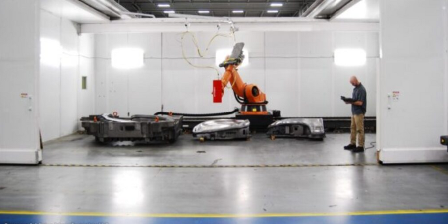
Automotive dies often require all the male radii to be heat treated to reduce the wear and improve die life. Conventional heat treating processes such as induction and flame have high heat input, which distorts the die. To account for this, the die makers leave extra stock material to later come back and hard mill the die to finish dimensions.
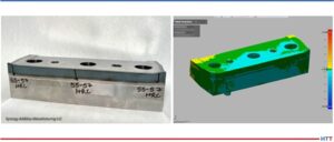
Laser heat treated trim inserts (approximate dimensions of 7″ x 4″ x 3″, base material 4140)
demonstrate distortion of less than 10 microns and hardness of 55-57 HRC
Source: Synergy Additive Manufacturing LLC
This additional hard milling step adds substantial cost to the die manufacturing process. Conventional processes are often performed by hand and lack feedback control. This results in poor quality and inconsistencies in the heat treated surfaces. Laser heat treating, on the other hand, results in minimal distortion. The dies are machined to their final form and laser heat treated as a final step, thereby reducing the process steps such as hard milling, 2D based machining, etc. This saves substantial time and costs for the die makers, not to mention improved and repeatable quality.
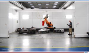
The laser heat treating process involves a laser beam (with a typical laser spot size from 0.5″ x 0.5″ to 2″ x 2″) focusing on the metal surface. With proper control, the incident laser energy raises the surface temperature of the metal above its martensitic transformation temperature. The metal’s thermal mass aids in rapid “self quenching” (by removing the heat via conduction), resulting in the formation of the desired martensite microstructure. This gives the material its required hardness and wear properties. To watch a video, go to: https://www.youtube.com/watch?v=8cUxEexAI9E.
By utilizing a laser beam, unrivaled precision is achieved by delivering the smallest possible energy to the metal part, resulting in minimal to virtually no distortion in large automotive dies. The unique characteristics of laser technology offer the following benefits:
Minimal to virtually no distortion
No hard milling required on large automotive dies
Consistent hardness depth (via. feedback control)
Heat Treatable Materials
Any metal with 0.2% or higher carbon content is laser heat treatable. Common materials used in automotive industry include: D6510, 0050A, A2, D2, S7, G3500, GM338, GM190, H13, 4140, 4130, 410 SS,431 SS, P20, 8620, and others.
Source: Synergy Additive Manufacturing LLC
When analyzing over 100 applicable die castings (post, cavity, and binders), Autodie LLC concluded that an average of 7-day reduction in time to market (TTM) was achieved by switching over to laser heat treating process. By avoiding hard milling operation, laser heat treating resulted in 37% reduction in machining time. Substantial savings in cutter cost were observed as the castings are now finished by 3D machining while in soft condition. Over an 11-month period, Kaizen savings had a benefit to cost average of 28.6 (Jonnalagadda and Timmer, “Laser Heat Treating”).
Conclusion
Laser heat treatment offers substantial cost savings as well as reduction in TTM. This process is likely to expand into the automotive and metal part manufacturing sectors. For example, Synergy Additive Manufacturing’s laser heat treating process is already being used in a variety of automotive applications such as trim dies, hot stamping dies, hem dies, restrike bars, flange dies, and molds. A variety of non-automotive parts such as large gears and bearings are also already being laser heat treated. Laser heat treatment faces no significant barriers to adoption, aside from the ones that are common to any emerging technology. These include lack of familiarity and a shortage of existing suppliers. The savings, measured by cost, schedule, quality, and energy reduction, are significant and well supported.
About the author:
Aravind Jonnalagadda (AJ) is the CTO and co-founder of Synergy Additive Manufacturing LLC. With over 15 years of experience, AJ and Synergy Additive Manufacturing LLC provide high-level laser systems and laser heat treating, specializing in high power laser-based solutions for complex manufacturing challenges related to wear, corrosion, and tool life. Synergy provides laser systems and job shop services for laser heat treating, metal based additive manufacturing, and laser welding.
A horizontal spray quench furnace has been completed for C/A Design’s heat treat facility in Exeter, NH. The system will help treat components for the aerospace and defense industry.
The furnace, from Wisconsin Oven, will be used for the solution treatment of aluminum. The system is designed to soak the product load at temperature in the furnace and then a pusher mechanism rapidly moves the load into the spray quench. The spray quench offers reduced distortion in comparison to submersion quenching.
The maximum temperature for this system is 1150°F and it has the capacity to heat a 200 pound aluminum load plus the work grid and product fixture. C/A Design’s new furnace has the capability to meet AMS 2750G, Class 2 furnace and Instrumentation Type D requirements.
Find heat treating products and services when you search on Heat Treat Buyers Guide.com
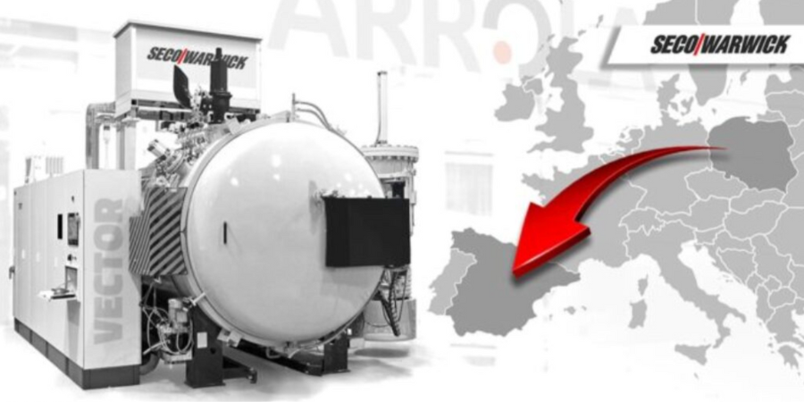
A service hardening plant in Spain will receive a vacuum furnace that is adapted to the aviation standard to perform production for this industry. The furnace will increase the company’s efficiency when hardening larger-dimension elements.
"The Vector [furnace] will enhance and increase the hardening processing capacity and will improve process efficiency," comments Maciej Korecki, vice president of the Vacuum Segment at SECO/WARWICK Group, a heat treat furnace supplier with North American locations. "The advantage of this product is a large working space with the capacity to adjust to an oversized load, utilizing the advantages of a circular heating chamber."
Find heat treating products and services when you search on Heat Treat Buyers Guide.com
An aerospace fastener manufacturer, operating since the mid-1900s, ordered a vacuum furnace. The equipment will process self-locking nuts, nut plates, barrel nuts, stud nuts, spline nuts, clamp nuts, as well as a wide range of washers and flanges.
The furnace from SECO/WARWICK Group, a global furnace technologies company that has locations in North America, will meet the AMS2750G standard in the second class (II) including B-type instrumentation for the aviation industry. The addition will become part of a modern production plant, in Italy, and will perform at high operating temperatures, up to 23720F.
“The heating process for these materials [fasteners] require extraordinary purity, which is why the presence of two gases is important: argon – used for partial pressure, and nitrogen – used mainly in the cooling process,” commented Maciej Korecki, vice president of the Vacuum Segment at SECO/WARWICK Group. “The customer required a very short cooling cycle, which is achieved with a 15 bar abs gas blower.”
Find heat treating products and services when you search on Heat Treat Buyers Guide.com
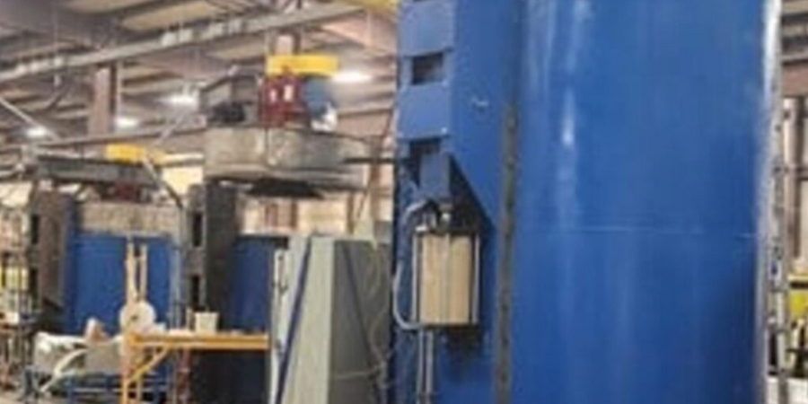
Three electrically heated RO pit furnaces with air-cooled fans have been shipped from Riverside, MI. The furnaces will be used for heat treating various steel components.
“These pit furnaces are designed for a nitrogen atmosphere,” commented Kelley Shreve, general manager at Lindberg/MPH. “They have been designed to utilize three independent heating zones for optimal temperature uniformity and meet AMS 2750G Class 3.”
These heat treating pit furnaces from have a maximum temperature rating of 2,000°F and are designed to handle a wide range of part sizes. Two of the units have work chamber dimensions of 28″ x 36” and a maximum gross workload of 2,000 lbs. each. The third furnace has work chamber dimensions of 60” x 109” and a maximum gross workload of 20,000 lbs.
All of the pit furnaces have pneumatically operated lids with three-way hand control valves and limit switches that disconnect power to the heating elements when the covers are open. The pit furnaces are electrically heated with heavy duty rod overbend heating elements.
Find heat treating products and services when you search on Heat Treat Buyers Guide.com
A vacuum furnace recently shipped to a U.S.-based aerospace fastener manufacturer. The furnace will be primarily used to age-harden various fasteners of high strength alloys used in the aerospace industry.
This is the second Model HFL-5748-2IQ furnace for this manufacturer. Like the first furnace, the new furnace features a graphite insulated hot zone of 36” x 36” x 48” deep with a weight capacity of 5,000 lbs., a maximum operating temperature of 2400°F, and a 100 HP quench motor. The control system was customized to interface with the customer’s in-house automation system for recipe control and data acquisition.
“Our customer needed additional furnace capacity to keep up with demand,” commented Jason Davidson, regional sales manager, Solar Manufacturing.
Find heat treating products and services when you search on Heat Treat Buyers Guide.com
MTU Aero Engines AG will receive a vertical vacuum furnace with the purpose of bringing heat treat in-house. The bottom-loading and gas cooling furnace will be used to process components for civil aircraft jet engines.
SECO/WARWICK Group, a global furnace technologies company with locations in North America, will supply the Vector® vacuum furnace. The equipment has an internal cooling gas blower as well as internal heat exchanger. The system is in accordance with the AMS2750G standard in the second class (II) including B-type instrumentation for the aviation industry.
“The aerospace/MRO industry is facing a major challenge. Interrupted supply chains and the difficult geopolitical situation in Europe means that many AEROSPACE/MRO companies have to revise their existing development and optimization strategies,” says Maciej Korecki, vice president of the Vacuum Segment at SECO/WARWICK Group. “[MTU’s] bringing the heat treatment process in-house with the purchase of this vacuum furnace allows the company to fully control the production process.”
Find heat treating products and services when you search on Heat Treat Buyers Guide.com