Methods of Measuring Retained Austenite
Most heat treaters recognize the importance of measuring retained austenite (RA), yet many opt not to perform these measurements due to time and/or cost constraints. This Technical Tuesday installment explains why performing RA measurements is necessary, the pros and cons of traditional measurement techniques, and the benefits of using more current and in plant technologies.
This informative piece was first released in Heat Treat Today’s March 2025 Aerospace Heat Treating print edition. To read the article in Spanish, click here.
Why Retained Austenite Percentage Matters
Before examining measurement methodologies, it is important to understand the fundamentals of retained austenite and why the percentage of retained austenite (RA%) matters.
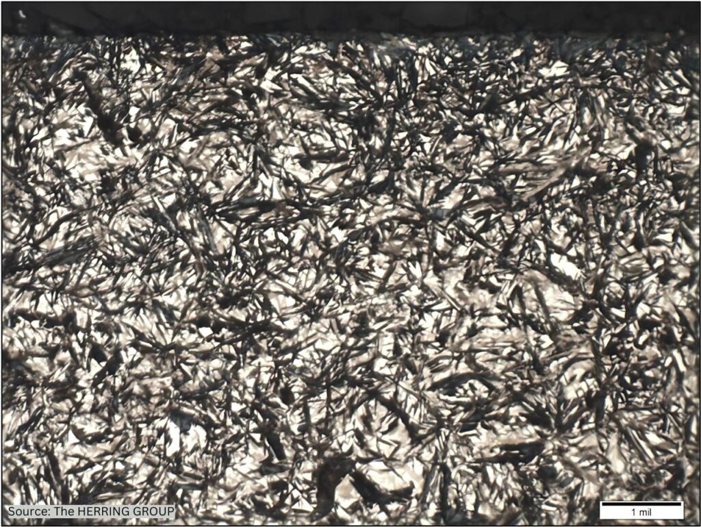
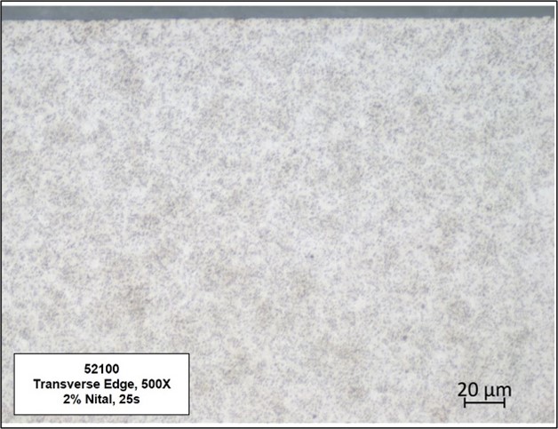
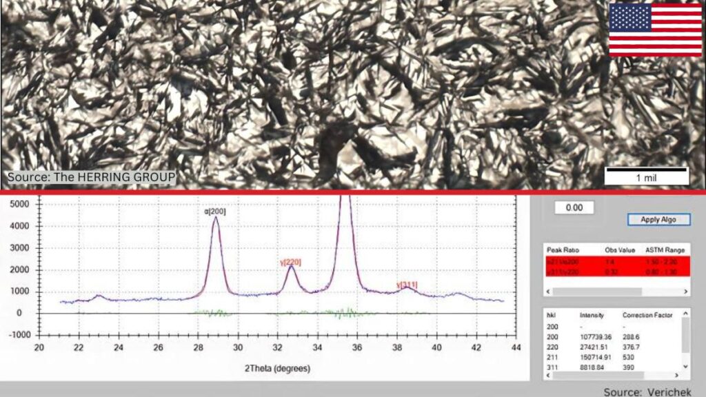
Austenite that does not transform to martensite upon quenching is called retained austenite (RA). In simple terms, retained austenite (Figure 1) occurs when steel is not fully quenched to the martensite finish (Mf) temperature; that is, low enough to form 100% martensite. Because the Mf is below room temperature in most alloys containing more than 0.30% carbon, significant amounts of retained austenite may be present within the martensite at room temperature (Herring, Atmosphere Heat Treatment).
When it comes to RA%, there is often a delicate balance between its beneficial effects (an increase in the life of certain manufactured components) and its negative attributes (the creation of parts that are prone to cracking and failure). For this reason, it is crucial that heat treaters achieve the optimal RA% for the intended application.
For example, in the aeronautics and astronautics industries, RA levels are often specified to be under 8% and, for devices such as bearings and linear actuators, RA under 3% and as close to zero as possible is required. In other applications, however, such as large gearing for power generation, wind energy, and performance platforms, in the range of 15–30% or more RA has been found beneficial (Errichello et al., “Investigations of Bearing Failures”). Also, high RA% has been found beneficial for bearings that will be subjected to contaminated lubricants.

Marco DeGasperi, technical manager at Verichek, weighed in on this, noting that for fuel injectors, small pieces in medical applications, and high-level, high-volume applications like wear plates in the mining industry, RA% is critical. He summarized with the statement, “When you’re applying pressure and motion to anything that’s fine-tuned … If you have ‘precision’ in your name, you probably want [an RA% measurement device].”
The very characteristics that give retained austenite many of its unique properties are those responsible for significant problems in service. We know that austenite is the normal phase of steel at high temperatures, but not at room temperature. Because retained austenite exists outside of its normal temperature range, it is metastable. This means that in service, factors such as temperature, stress, and even time will see it transform into untempered martensite. In addition, a volume change (increase) accompanies this transformation and induces a great deal of internal stress in a component, often manifesting itself as cracks, which leads to parts failing in the field.
RA% is also important not only because of its influence on dimensional stability but on mechanical properties such as yield strength, fatigue strength, toughness, and machinability (Herring, Atmosphere Heat Treatment). For example, looking in the automotive industry, DeGasperi gives an example of the consequences of having too high or too low RA%: “Let’s say pieces in a transmission or a transfer case; this is when gears start breaking or you get issued wide-end recalls. And then usually the supply chain all starts blaming the guy before them when nobody throughout the supply chain has actually tested the parts themselves.”
Alternatively, in some cases, finely dispersed RA helps the material resist the propagation of fatigue cracks and improves rolling contact fatigue stress, so balancing the amount of RA is important in many applications. Also, the correct RA% is essential for quality control, and proper control and accurate measurement of RA% in steel alloys is crucial to guaranteeing the quality and safety of finished components, as well as protecting the reputation and profitability of heat treaters and manufacturers.
RA Measurement Methods
Accurate RA measurements are critical to determine whether the correct balance of retained austenite and martensite exists within a given part. Several RA measurement methodologies are available to heat treaters, each having their own unique set of advantages and disadvantages. For heat treaters, understanding why it is crucial to measure the percentage of RA is only half the battle. Finding a cost-effective, fast, and accurate measurement method is the other half.
X-Ray Diffraction: The Best and Most Accurate Method

X-ray diffraction, which is used to identify and quantify phases in a material, is considered the most accurate method of RA measurement in steels as it can precisely determine RA levels down to the range of approximately 0.5–1% (GNR, “AreX Diffractometer,” 3). In X-ray diffraction, different crystalline phases have different diffraction patterns, allowing them to be identified and measured. In addition to phase analysis, X-ray diffraction can be used to analyze microstructural features such as texture, residual stress, and grain size.
Today, X-ray diffraction is a non-destructive, safe solution that can sample a much larger region than many other available methods and does not involve much sample preparation and analysis, making it a more efficient and effective solution. This is the option of choice for a company that needs to test RA with expected readings under 10%.
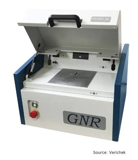
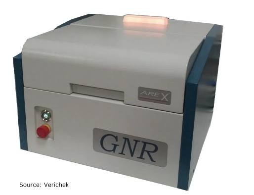
The current generation of X-ray diffractometers are tabletop sized, weighing about 25 lbs. With models under $100,000, they are also cost-effective when compared to traditional X-ray diffractometers ($200,000), which were sometimes problematic in the presence of additional phases and reflections due to grain size, carbides, or textures that could cause disturbances and variances in measurement. The new generation of X-ray equipment compensates for these obstacles via the use of multiple diffraction peaks to minimize the effects of preferred orientation and detect interference from carbides.

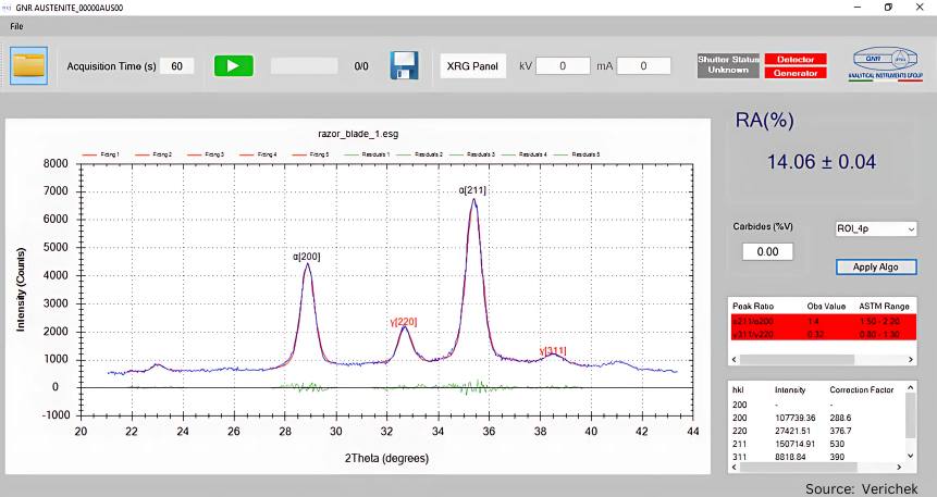
Modern X-ray diffraction machines can collect up to seven diffraction peaks (three for ferrite/martensite phase and four for austenite phase) and then determine the volume percent concentration of RA in the sample by comparing the intensities of the peaks and analyzing the peak ratios in accordance with the ASTM E975-22 (standard practice for X-ray determination of retained austenite in steel with near random crystallographic orientation).
The use of today’s X-ray diffraction equipment is not complicated. It can be measured in under three minutes by simply placing the sample in the machine and pressing the start button. These X-ray diffractometers measure various-sized samples and use intuitive software so the measurement can be performed quickly, accurately, and efficiently by any technician — with or without prior metallurgical or diffraction experience.
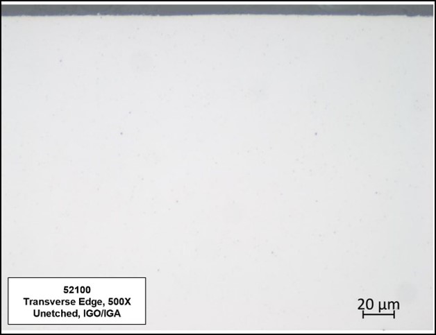
Optical Microscopy — A Time-Proven Method
RA can be measured metallographically with an optical microscope. An experienced metallurgist can usually determine RA% down to approximately 10–15% RA. For many applications, this is more than adequate and has the added benefit of characterizing the microstructure as well.
This method, which involves determining the austenite fraction using contrast from etching behavior or morphology, is low cost, however, it can be somewhat time consuming. Charts and diagrams in reference books are available to help determine the percentage of retained austenite by comparative methods. Optical microscopy is subjective as it is dependent upon the individual and their interpretation of the sample under the microscope.

Alternative Methods
Several other methods for measuring RA are available to heat treaters. The most common of these methods includes:
Magnetic Induction: Here, a sample is magnetized to saturation and the saturation polarization is measured. The difference between measured and theoretical saturation of the RA can then be calculated using this equation:

Magnetic induction is non-destructive and offers a higher, broader range than optical microscopy (1–30%). However, because it is a volume measurement, the instrument needs to be calibrated to the specific materials, heat treatment, and geometries, which is time consuming and highly dependent on the skill of the technician.
Electron Backscatter Diffraction (EBSD): Using this RA measurement method involves placing a sample in a Scanning Electron Microscope (SEM) to characterize the crystallographic structure as well as the microstructure. RA measurements using this technique are not particularly accurate and are reliant upon proper sample preparation. Additionally, it provides a very small measure volume and is a destructive test method.
Conclusion
Accurate measurement of the level of retained austenite allows both the design engineer and metallurgist to maximize its beneficial effects without suffering from its negative consequences. On the part of the heat treater this means taking into account the material chemistry and the heat treat process variables such as austenitizing temperature, quench rate, deep freeze or cryogenic treatments, and tempering temperatures.
References
Errichello, Robert, Robert Budny, and Rainer Eckert. “Investigations of Bearing Failures Associated with White Etching Areas (WEAs) in Wind Turbine Gearboxes.” Tribology Transactions 56, no. 6 (2013): 1069–1076.
GNR, Analytical Instruments Group. “AreX Diffractometer: GNR Proposal for measuring Retained Austenite in the industrial domain and in laboratory.”
Herring, Daniel H., Atmosphere Heat Treatment. Volume I. Chicago: BNP Media, 2014.
Acknowledgments
We’d like to thank the following contributors for the support of this article: Thomas Wingens, President & Heat Treat Specialist, WINGENS CONSULTANTS; Dennis Beauchesne, General Manager, ECM USA; Tim Moury, President & CEO, Marco DeGasperi, Technical Manager, Jeff Froetschel, VP & CFO, Verichek Technical Services, Inc.; and Dan Herring, The Heat Treat Doctor®, The HERRING GROUP, Inc.
This article is provided by the Heat Treat Today Editorial Team.
Find heat treating products and services when you search on Heat Treat Buyers Guide.Com
Methods of Measuring Retained Austenite Read More »