featured

Ask The Heat Treat Doctor®: What Oil Quenching “Tricks” Help Manage Distortion?

Ask The Heat Treat Doctor® has returned to bring sage advice to Heat Treat Today readers and to answer your questions about heat treating, brazing, sintering, and other types of thermal treatments as well as questions on metallurgy, equipment, and process-related issues. In this installment, Dan Herring discusses practical strategies for managing distortion through oil quenching, focusing on how subtle adjustments — such as delaying agitation to extend the vapor blanket phase — can influence heat transfer behavior and improve dimensional stability in challenging geometries like thin-walled, large-diameter gears.

This informative piece was first released in Heat Treat Today’s April 2026 Annual Induction Heating & Melting print edition.


The Question

A reader’s question caught the Doctor’s eye and will provide some valuable information we all can benefit from. Let’s learn more:

“I have a question about a technique we used sometimes in my factory for distortion reduction. As you know, in the oil quench cooling there are 3 steps:
1. Vapor Blanket Phase (≈ 840–700°C)
2. Boiling Phase (≈ 700–400°C)
3. Convection (≈ 400–40°C)
In addition to [running] a martempering oil (Houghton M240) and a high oil temperature of 80–100°C, a technique we used successfully to reduce the distortion in thin wall large (> 1m) gears was to wait 1 minute without agitation just after placing the parts in the oil tank. Once the minute has passed, we start with the agitator speed at 1,700 rpm.
The technical reason for this improvement is to extend the vapor blanket step and hence reduce the distortion created by the boiling step. My questions are: What effect does the vapor blanket step have on thermal uniformity, and is it possible to get a similar result in the agitator speed, for instance, start with a low rotating speed and finishing with a high speed?”

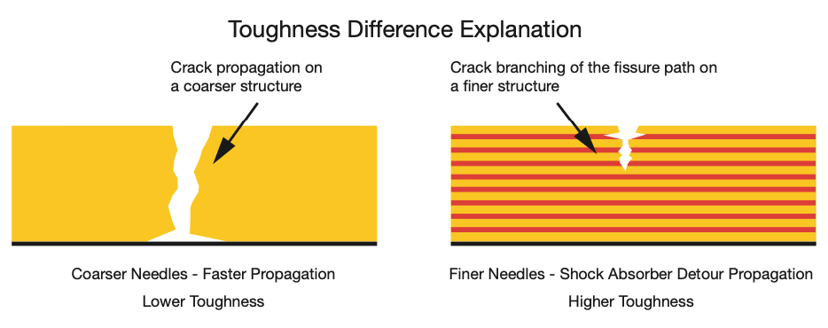
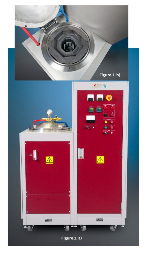
The Three Phases of Quenching

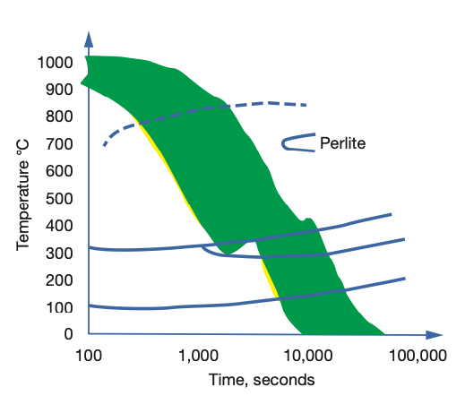
As a brief reminder, let’s revisit the three distinct stages of cooling (Figure 1). The first stage, the “vapor blanket” (or “film boiling”) stage, is characterized by the Leidenfrost phenomenon, which is the formation of an unbroken vapor blanket that surrounds and insulates the work piece. It forms when the supply of heat from the surface of the part exceeds the amount of heat that can be carried away by the cooling medium.

The stability of the vapor layer, and thus the ability of the oil to harden steel, is dependent on: the metal’s surface irregularities; oxides present; surface-wetting additives, which accelerate the breakdown and destabilize the vapor blanket; and the quench oil’s molecular composition, including the presence of more volatile oil degradation by-products (Herring 2015). In this stage, the cooling rate is relatively slow in that the vapor envelope acts as an insulator, and cooling is a function of conduction through the vapor envelope.

The second stage, the “vapor transport” (or “nucleate boiling” or “bubble boiling”) stage, is where the highest heat transfer rates are produced — and where the greatest amount of distortion occurs. The point at which this transition occurs and the rate of heat transfer in this region depend on the oil’s overall composition (base oil, speed accelerators, and antioxidant package). It begins when the surface temperature of the part has cooled enough so that the vapor envelope formed in the first stage collapses. Violent boiling of the quenching liquid results, and heat is removed from the metal at a very rapid rate, largely due to heat of vaporization. The boiling point of the quenchant determines the conclusion of this stage. Size and shape of the vapor (bubbles) are important in controlling the duration of this stage.

Figure 1. The three stages of liquid quenching | Image Credit: The Heat Treat Doctor®

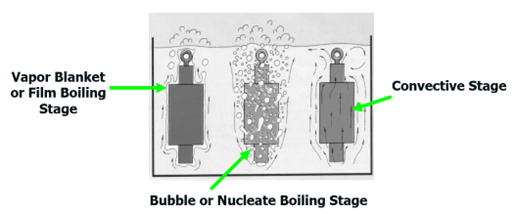
The third stage of cooling is called the “convection” (or “liquid”) cooling stage. The cooling rate during this stage is slower than that developed in the second stage and is exponentially dependent on the oil’s viscosity, which will vary with the degree of oil decomposition. Heat transfer rates increase with lower viscosities and decrease with increasing viscosity. This final stage begins when the temperature of the metal surface is reduced to the boiling point (or boiling range) of the quenching liquid.

The Answer

A sage veteran once reminded the Doctor that we cannot control distortion, only manage it.

As we know, if we were able to control the heat transfer during the nucleate boiling phase, the result would be less gear distortion, especially when the geometry (in this case thin wall, large diameter gears) makes it even more challenging.

What many people do not realize is that in addition to the correct choice of oil, oil temperature, the proper size and design of the quench system (which is fixed for all part or load configurations), and the uniform removal of the vapor blanket in the first stage of quenching influences the development and type of heat transfer that will occur in the nucleate boiling phase — yes, it is uncontrolled, but it can be influenced.

A delay in the start of agitation ensures the vapor blanket phase is extended and (in a sense) more uniformly conforms to the part geometry than it would otherwise. The result is that it is easier to be uniformly swept away once the agitation begins. Interestingly, the vapor blanket begins to form within the first few seconds of quenching and begins to collapse (often in a nonuniform way) as the surface temperature drops. Agitation delay times ranging from 1 to 2 minutes have been used in industry, which are primarily a function of material, (gear) geometry, and tooth profile/thickness.

As to the other question, some manufacturers recommend quenching into slowly agitated oil (100–125 rpm) — the slower agitation only intended to push any moisture molecules around, then increasing the speed to normal agitation rates once the load is fully submerged. Appropriate safety precautions must be followed with either method. A great deal of success has been reported using this method for many of the same reasons as above.

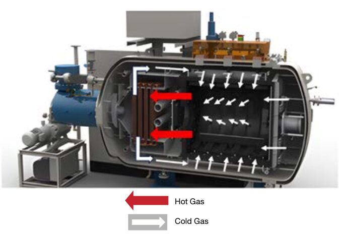
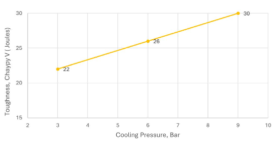
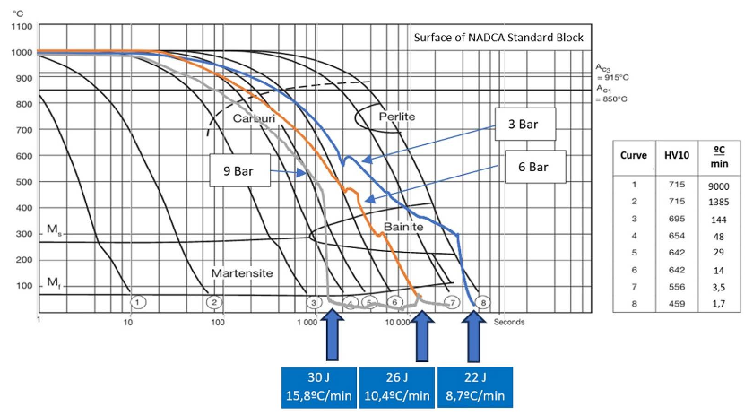
On another note, there is some merit in vacuum oil quenching to vary the pressure over the oil. Interestingly, the characteristics (i.e., size and distribution) of the “bubbles” formed in the nucleate boiling phase changes and the end result is that they can be more easily and more uniformly swept away.

In Summary

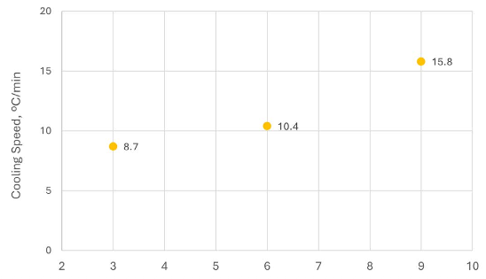
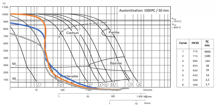
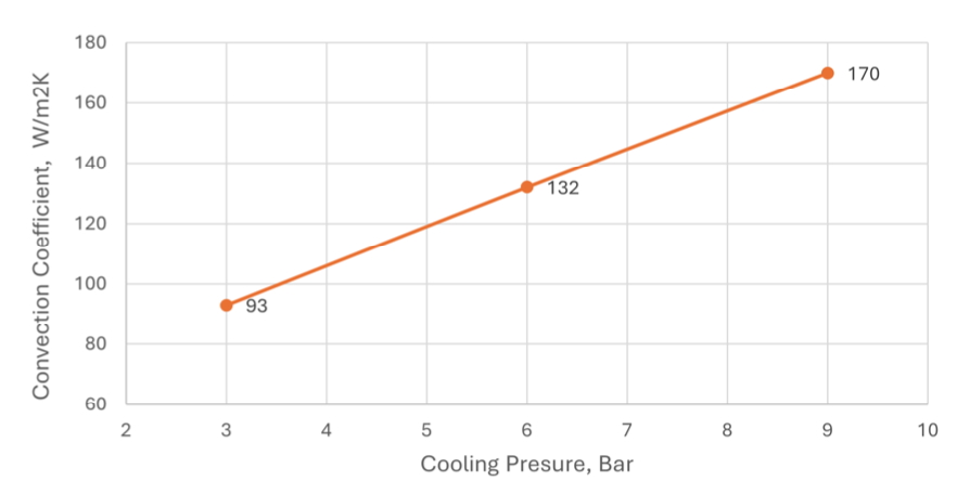
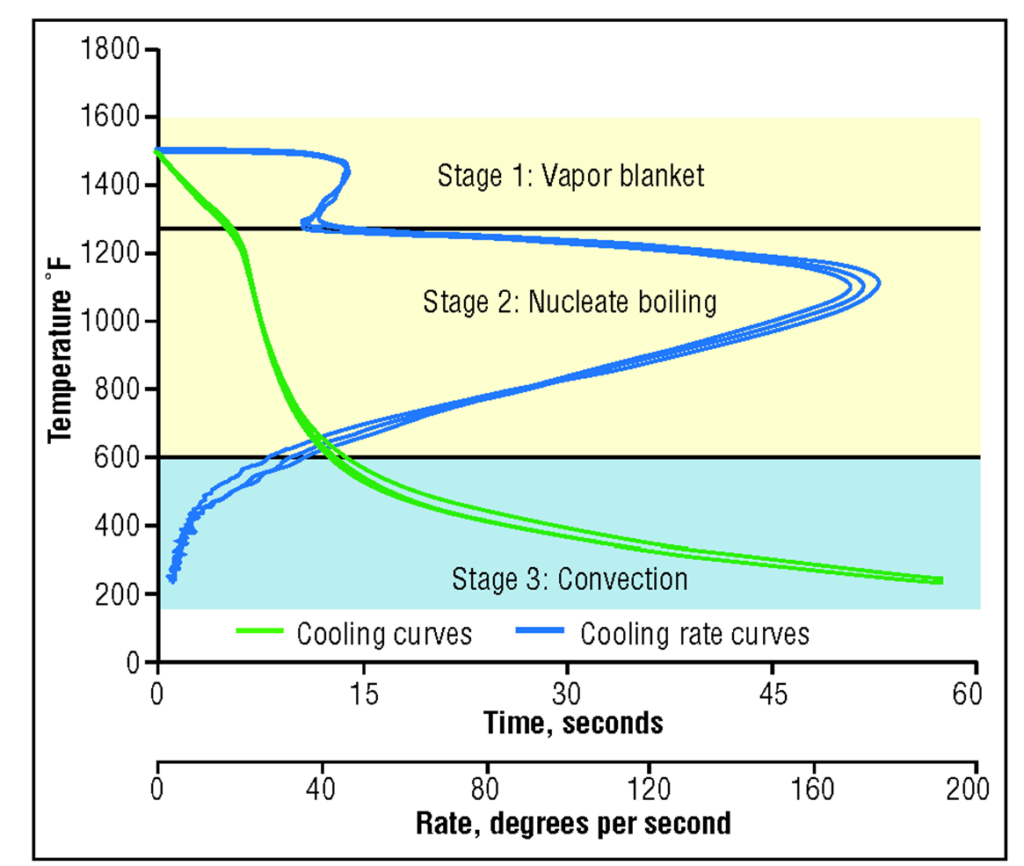
A word or two is in order about measuring and maintaining the quench oil. Measuring the efficiency (i.e., speed) of an oil can be done in one of two ways. The first method is by measuring the oil’s cooling ability (i.e., hardening power). Since cooling ability is independent of steel selection (composition and grain size) this method is popular since it provides information about the oil itself independent of its end use application (Figure 2).

Figure 2. Typical cooling curves and cooling-rate curves for new oils | Image Credit: The Heat Treat Doctor®
Table A. Classification of Quench Oils

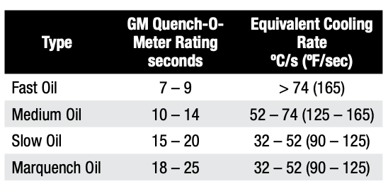
The older GM Quench-O-Meter method (Table A) can be used as well.

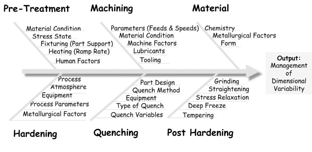
Variables Affecting Dimensional Change

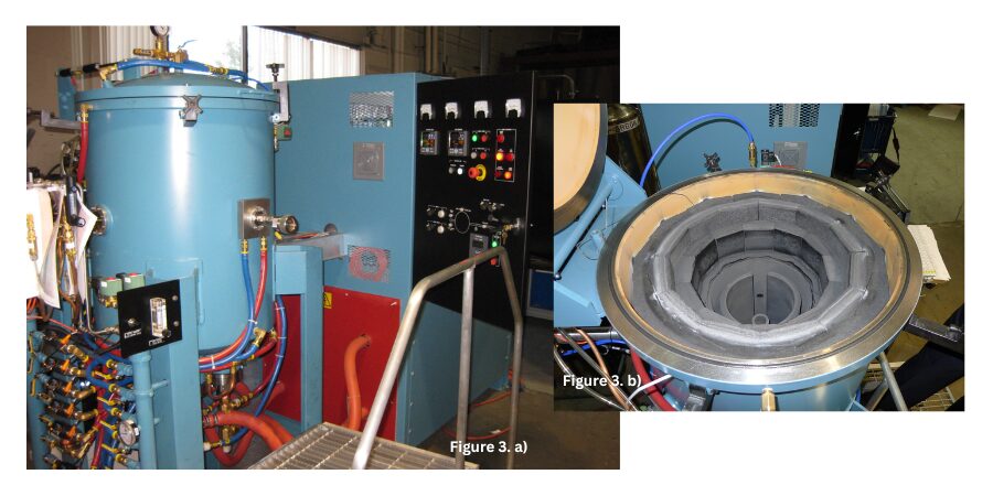
A number of factors influence post-heat treat distortion, including those related to material, manufacturing, and heat treating (Figure 3).

Figure 3. Distortion (Ishikawa) diagram | Image Credit: The Heat Treat Doctor®

When selecting an oil quench process, some of the many factors to consider include:

  • Material — form, chemistry, hardenability, grain size, homogeneity, cleanliness, microstructure
  • Heat treatments performed at the mill
  • Starting microstructure — mill or third-party heat treating prior to manufacturing
  • Manufacturing process — sequence of operations, tooling, speeds & feeds
  • Part orientation during manufacturing, as opposed to grain orientation
  • Grids, baskets, and fixtures — both material & design
  • Load configuration — part spacing, orientation, arrangement (load density)
  • Load weight (gross or net)
  • Maximum quench fixture size, weight, shape
  • Part geometry and mass — maximum/minimum part section thickness, consideration for whether the component part is uniform in thickness or has thin and thick sections next to one another
  • Residual stress state before heat treatment
  • Targeted hardness range (initial or final)
  • Type of process being run (e.g., hardening, case hardening)
  • Free quenching or restricted (press or roll) quenching
  • Oil type — quenching characteristics, cooling curve data
  • Oil speed, condition, viscosity (fast, 7–9 second oil; medium, 10–14 second oil; slow, 15–18 second oil; or marquench, >20 second oil)
  • Oil temperature (initial, instantaneous rate of rise, recovery time to initial temperature)
  • (Effective) quench tank volume
  • Height of oil above the load
  • Agitation — agitators or pumps
  • Quench tank design factors
    • Agitation method and number of agitators or pumps
    • Type of quench tank baffling
    • Location/size of agitators or pumps
    • Type of agitators (e.g., fixed, two speed, variable)
    • Propeller size (e.g., diameter, clearance in draft tube)
    • Internal tank baffling (e.g., draft tubes, directional flow vanes)
    • Flow direction
    • Flow restrictions (quench elevator and baffling design)
    • Volume of oil
    • Maximum (design) temperature rise
    • Heat exchanger-type, size, heat removal rate (instantaneous and total demand)
    • Quench elevator design (e.g., hearth type, sidewalls, flow restrictions)
  • Flow velocity (with and without a load present)
  • Number of furnaces to be served by the quench system
  • Duty cycle (i.e., the frequency of quenching or time between quenches)
  • Post heat treatment operations, if applicable
  • Furnace temperature uniformity
  • Furnace repeatability
  • Type of furnace atmosphere
  • Post processing (e.g., washing, deep freeze or cryogenic treatment, number of tempers)
  • Time delay between heat treat operations (especially important for high hardenability materials to avoid cracking)

References

Herring, Daniel H. 2015. Atmosphere Heat Treatment. Volume 2, BNP Media II.

About the Author

Dan Herring
“The Heat Treat Doctor”
The HERRING GROUP, Inc.

Dan Herring has been in the industry for over 50 years and has gained vast experience in fields that include materials science, engineering, metallurgy, new product research, and many other areas. He is the author of six books and over 700 technical articles.

For more information: Contact Dan at dherring@heat-treat-doctor.com.

For more information about Dan’s books: see his page at the Heat Treat Store.


Ask The Heat Treat Doctor®: What Oil Quenching “Tricks” Help Manage Distortion? Read More »

Improve Vacuum Quench, Maximize Tool Life

Vacuum furnaces performing hardening have been in use for over 50 years, yet many heat treaters may not be taking full advantage of newer, more advanced analysis tools and methods. Controlling the cooling pressure can dramatically improve toughness and tool life, but only if applied with precision. In this Technical Tuesday installment, Paulo Duarte, technical director at Treatnorte, explores the science behind gas quenching, the role of step cooling, and why measuring and adjusting cooling curves is critical for consistent, high-performance results.

This informative piece was first released in Heat Treat Today’s March 2026 Annual Aerospace Heat Treating print edition.


Introduction

It has been a long time since the invention of the vacuum hardening process, yet innovation in this field continues. In recent years, industrial furnaces capable of operating with higher cooling gas pressures — up to 15 bar now commonly offered on the market — have become standard. But do we truly know how to make the best use of such high pressures?

Pressures up to 10 bar were first applied to cool small parts made from cold-work tool steels, such as sheet metal stamping tools. However, such high pressures can lead to cracking in larger hot-work steel dies when cooled directly. Step cooling was introduced as a solution: start with a fast initial cooling at higher temperatures to avoid carbide formation, then gradually lower pressure stages during the final cooling phase to reduce distortion and minimize the risk of crack appearance.

Despite this empirical knowledge, the question remains: do we really understand what we are doing? Are we routinely measuring cooling rates to determine where they stand on the CCT diagram, predicting microstructure and properties, and adjusting quenching parameters accordingly? And are we certain about which pressures to use for producing high-performance, demanding tools?

Cooling in Vacuum Furnaces

Quenching is one of the most critical steps in the hardening cycle. It transforms austenite into the optimal final microstructure, avoiding the formation of coarse carbides and pearlitic constituents during cooling. This ensures the finest possible microstructure.

Figure 1. Gas quenching in a vacuum hardening furnace | Image Credit: SECO/WARWICK
Figure 2. Surface cooling rates region on systematic analysis of parts quenching in a 600 mm x 600 mm x 900 mm furnace. Parts comprising weights from 500 up to 1,000 kg. Cooling pressures varies from 4 to 5 bar. Hot work tool steel. | Image Credit: Metaltec Solutions

In vacuum furnaces, this is typically achieved by injecting cooling gas through nozzles directed at the surface of the parts located in the furnace hot zone. During cooling, the gas circulates through the chamber, being drawn through furnace ports into contact with the heat exchanger tubes. A turbine then blows the cooled gas back into the hot zone where the load is located (Figure 1).

The higher the programmed cooling pressure, the greater the volume of gas passing through the nozzles over the same period of time. This increases the heat transfer from the parts to the cooling gas, resulting in a faster cooling rate.

By measuring successive cooling curves for different loads, specifically for single hot-work steel tools weighing over 500 kg, surface cooling rates pass through the bainitic–martensitic domain (the green area of the CCT diagram shown in Figure 2). Thinner parts tend to cool closer to the martensitic end at the Ms-Bs intersection, while larger tools tend to approach the pearlitic nose.

These observations highlight the importance of adjusting cooling pressure to produce the desired microstructure and account for the different cooling behaviors of large, medium, and small parts.

Investigative Approach: Testing Furnace Data Against CCT Diagrams

Measuring part temperatures during cooling began over 20 years ago, using thermocouples and data loggers, and comparing the results to steel continuous cooling transformation (CCT) diagrams. Most vacuum furnaces do not include this capability as standard, and when available as optional software, many companies choose not to invest in it. In 2005, it was discovered what few in the industry knew at the time: hardening hot-work tool steels in industrial vacuum furnaces often results in a bainitic–martensitic microstructure. This phenomenon is now more widely recognized, with published cooling curves overlaid on CCT diagrams for larger tools becoming more available.

Even so, open discussion remains rare, partly because many heat treaters are reluctant to present this evidence to academia, fearing criticism that their results do not match the fully martensitic microstructure taught at universities. This is not a debate about right or wrong, but rather an opportunity for research and improvement in heat treatment practices worldwide.

After initial testing with a 600 mm × 600 mm × 900 mm French-made single-chamber furnace, trials continued with a larger 900 mm × 900 mm × 1,800 mm German-made vacuum furnace. These tests began by measuring both surface and core temperatures for repeated cycles with small and large charges ranging from small cold-work tools to hot-work tool steel parts weighing 500–1,500 kg. Leading vacuum furnace manufacturers in North America and Europe have developed technologies capable of successfully heat treating small, medium, and large tools, resulting in microstructures that often contain both bainite and martensite. This is, in fact, an inherent characteristic of the technology. Such tools have performed well in service for decades. That said, heat treaters using higher cooling pressures have seen improved tool life significantly, while also increasing the risk of treatment failures if the pressure is too high.

In the last 10 years, properties and microstructure analyses have shown that variations in cooling rate can significantly change the microstructure and toughness of the part even within the same bainitic–martensitic domain of the CCT diagram.

With the emergence of Industry 4.0 and 5.0, along with digitalization and AI, systematic research into heat treatment processes combined with quenching deformation simulation can lead to better selection of cooling pressures. This is a critical parameter in controlling the hardening process, and it has a direct impact on part toughness and service performance. Metaltec Solutions introduced one of the first software tools aimed at improving vacuum heat treatment through Industry 4.0 concepts in 2017. This technology represents a step toward greater awareness and precision in tool steel hardening, helping heat treaters program their cycles for optimal performance in demanding applications.

Regulating Pressure in Vacuum Hardening Furnaces

To obtain the best possible microstructures, gas quenching must be programmed in the furnace so that the cooling rate is kept as close as possible to the martensitic end, i.e., at the Ms-Bs intersection, of the CCT diagram, avoiding the formation of coarse and undesirable microconstituents in the steel. This is achieved by selecting the highest permissible cooling pressure that still prevents cracking or excessive deformation. While small parts can withstand direct high-pressure cooling, larger tools require a reduction in cooling pressure.

Preliminary Pressure Comparison

For optimal quenching of large parts, the cooling pressure should not remain constant throughout the entire cooling cycle. Instead, high pressure should be applied during the initial cooling stage to prevent coarse carbides and pearlite formation and then reduced when the surface temperature reaches approximately 550°C (1022°F). This creates a martempering stage at lower pressures, reducing the risk of distortion and cracking.

Figure 3a. Cooling pressure effect on Vidar Superior (an H11 steel grade
variation) part surface toughness | Image Credit: Metaltec Solutions
Figure 3b. Cooling pressure effect on 400 mm x 400 mm x 400 mm
block surface toughness | Image Credit: Metaltec Solutions

If we measure the toughness of steel pieces quenched at different cooling pressures, then tempered together to achieve a typical 46–48 HRC hardness (in hot work tool steel), we find that higher cooling pressures result in greater toughness. Using older furnace pressures (around 3 bar) yields lower toughness, whereas increasing cooling pressure can improve toughness by approximately 60% (Figure 3a). This translates into longer tool life, since high-pressure-quenched tools better absorb stress, delaying the initiation and propagation of cracks. These benefits result from higher cooling rates (Figure 3b) and the corresponding finer microstructures achieved.

Although quenching at 3, 6, and 9 bar passes through the same transformation domain on the CCT curve, differences in the resulting internal steel structure, whether coarser or finer, are clearly observable.

True Toughness and Speed

Looking in more detail at the above findings, we can observe that when parts are cooled in a 900 mm × 900 mm × 1,800 mm vacuum furnace, the gas temperature drops below the Ms temperature (for typical hot work tool steels) in less than one minute. The gas temperature then remains near room temperature during the subsequent cooling of the parts (Figure 4a).

Figure 4a. Cooling NADCA block in a large vacuum hardening furnace; gas cooling rate according to gas pressure used | Image Credit: Metaltec Solutions
Figure 4b. Cooling NADCA block in a large vacuum hardening furnace; surface cooling curves and its respective toughness after tempering, with the alteration of the cooling curve behavior provided by the martempering (final hardness level 46–48HRC hot work tool steel | Image Credit: Metaltec Solutions

The parts, however, take considerably longer to cool down to the furnace unloading temperature, depending on the cooling pressure applied. When analyzing the cooling of large dies using the NADCA block as the standard size for comparison, the surface cooling curves vary according to the applied pressure, falling into the bainitic–martensitic domain for 3, 6, and 9 bar cooling pressures.

From this data, it can be seen that hardness is not significantly affected by using 3, 6, or 9 bar cooling pressures, even though the higher pressures produce cooling rates up to twice as fast as the slower ones. Toughness, however, is largely influenced by the way the cooling curves pass through the bainitic–martensitic domain, whether crossing the Bs and Ms intersection closer to the martensitic end (9 bar), near the center (6 bar), or closer to the pearlitic nose (3 bar).

Tuning Pressure and Time

These results show that, within the typical cooling rates of vacuum hardening (Figure 2), toughness varies significantly with cooling pressure, corresponding to finely tuned cooling speeds ranging from approximately 9 to 16°C/min (48 to 61°F/min) between 800°C and 500°C (932°F and 1472°F). This highlights the need to use the highest possible cooling pressures to achieve excellent properties while avoiding direct high-pressure cooling of large parts by applying step cooling with an initial fast cooling phase, followed by reduced pressure.

How Microstructure Drives Toughness

The reason for achieving better properties at higher cooling pressures lies in the resulting microstructure, as shown in Figure 5. Fine bainite and martensitic needles, formed through faster cooling rates, are responsible for the higher toughness observed. When lower cooling pressures are used, the cooling rate decreases, leading to coarser needle sizes (Figres 5a–c) and, consequently, lower toughness values.


Figure 5a-c. Microstructures obtained after quenching Orvar Supreme (premium H13 steel): a) 100°C/min; b) 12°C/min; c) 3°C/min (or, a) 180°F/min; b) 22°F/min; c) 5°F/min) | Image Credit: Metaltec Solutions
Figure 6. Toughness model | Image Credit: Metaltec Solutions

This can be explained by Figure 6. In a coarser microstructure, cracks can propagate more easily because there are fewer obstacles to their advance. In finer microstructures, the higher density of needles forces cracks to deviate repeatedly from their path due to the branching effect, altering the directions of crack propagation. This “shock absorber” effect — caused by the frequent detours a crack experiences when traveling through a greater number of fine needles — is the reason for the toughness improvement observed when higher cooling pressures are used to achieve faster cooling rates.


Figure 7. Convection coefficients for a 900 mm × 900 mm × 1,800 mm vacuum hardening furnace according to the pressure being used | Image Credit: Metaltec Solutions

Each furnace behaves differently, from one furnace builder to another and also depending on the level of maintenance of a furnace. So a similar furnace to the one used for obtaining cooling curves and corresponding toughness values (Figure 4b) was used to obtain the convection coefficients (Figure 7). We can see a strong correlation between convection coefficient, pressure, and final toughness obtained, indicating that these features must be carefully adjusted to reach optimal part properties and longer service life.

Conclusion

Properly applying cooling pressures, through direct high-pressure cooling for small loads or step cooling for larger tools, can significantly increase part toughness and extend tool life. The key lies in understanding how cooling curves interact with the bainitic–martensitic microstructure and adjusting pressure according to part size, geometry, and furnace characteristics.

By measuring temperatures, analyzing microstructures, and fine-tuning cooling cycles, heat treat operators can achieve consistent, high-performance results, as demonstrated with the above studies on tool steels. Faster, well-controlled cooling typically produces finer bainitic–martensitic microstructures which results in a part with “shock absorber” qualities.

Ultimately, maximizing cooling pressure, not just for minimal distortion, creates more durable tools, reduces downtime, and strengthens competitiveness through part performance.

About The Author:

Paulo Duarte
Technical Director
Treatnorte

Paulo Duarte is an independent researcher and consultant on heat treat technologies, also working as technical director at Treatnorte. His education and expertise in metallurgy have culminated in several articles and patents. Previously, he was the project manager at Metalsolvus and also had been the technical manager and heat treatment manager within bohler-uddeholm group for the Portuguese market. Currently, Paulo focuses on helping heat treaters by providing innovative, more efficient, and profitable heat treatment services to companies.

For more information: Contact Paulo Duarte at pauloduarte@treatnote.pt.

Improve Vacuum Quench, Maximize Tool Life Read More »

Groundbreaking Marks Heat Treat Furnace Expansion In Iowa

Advanced Heat Treat Corp. (AHT), a global provider of commercial heat treat services and metallurgical solutions, is expanding its Waterloo, Iowa, facility to increase capacity for carburizing, through hardening, normalizing, and other heat treatment processes. The 18,000 sq. ft. project broke ground on April 6 and is expected to be completed by fall 2026.

The expansion will include a custom-built furnace designed to accommodate larger components in length, height, and weight. “This expansion is about giving our [clients] more — more capacity, more capability, and more confidence in turnaround,” said Adam Kane, plant manager at AHT’s Waterloo facility pictured above. “With added production space and additional equipment, we’ll be able to process larger and heavier components, and we’ll have room to add even more equipment and services in the future.”

Mikel Woods
President
Advanced Heat Treat Corp.

The facility, in operation at Burton Ave. since 1981, provides services including induction hardening, annealing, cryogenic treatment, carbonitriding, and stress relieving. A second Waterloo location on MidPort Blvd. serves as the company’s corporate office and offers nitriding and nitrocarburizing services.

“Between the two Iowa locations, [clients] have access to multiple heat treatments within a short drive, allowing them to consolidate their vendors and potentially reduce freight costs,” added Mikel Woods, president of AHT.

Press release is available in its original form here.
Main image shows AHT plant manager Adam Kane standing on the construction site of the 18,000 sq. ft. building expansion in Waterloo, Iowa.

Groundbreaking Marks Heat Treat Furnace Expansion In Iowa Read More »

Allied Graphite Develops Vertical Furnace Systems

Allied Graphite, a U.S.-based graphite materials manufacturer, is advancing the high-temperature thermal processing of its battery-grade material with a new technology partnership. This partnership to develop, validate, and provide engineering data for vertical furnace solutions will support the company’s progress toward commercial-scale production.

The effort aims to design, test, and refine vertical furnace configurations in partnership with Harper International, a U.S.-based global provider of high-temperature thermal processing systems for advanced materials, and ONEJOON GmbH, a global supplier of high-temperature thermal processing equipment. The systems are intended to support processing steps required for battery-grade graphite production.

As part of the collaboration, Harper International is contributing engineering and validation programs conducted at Harper’s Technology Center in Buffalo, New York. Meanwhile, the partnership with ONEJOON GmbH will include joint engineering work and advanced development activities intended to support the design and validation of commercial-scale furnace configurations.

Andy Goshe
Chief Executive Officer
Allied Graphite

“Thermal processing performance is fundamental to delivering consistent product quality at scale. These partnerships reflect our commitment to rigorous engineering validation and disciplined equipment selection as we advance toward commercial-scale operations,” said Andy Goshe, chief executive officer of Allied Graphite.

The collaboration includes engineering development and validation programs to evaluate furnace designs under production conditions. The work is expected to generate process data to inform final equipment selection and support the transition from pilot-scale validation to commercial manufacturing.

High-temperature thermal processing is a key component of graphite production. Vertical furnace systems are being assessed for performance and scalability in production environments, key considerations as demand grows in the battery sector.

Press release is available in its original form here.

Allied Graphite Develops Vertical Furnace Systems Read More »

26 News Chatter to Keep You Current

Heat Treat Today offers News Chatter, a feature highlighting representative moves, transactions, and kudos from around the industry. Enjoy these 26 news items, including Boeing’s addition of vacuum furnace capacity to expand in-house heat treating for aerospace components, Solar Atmospheres’ role in supporting thermal processing for materials used in NASA’s Artemis II mission, Aalberts surface technologies’ renewal of Nadcap certification for another 24 months, and more!


Equipment

1. HWI, a member of Calderys Group, has opened a new lightweight monolithics production facility in Fulton, Missouri to expand manufacturing capacity for refractory materials used in high-temperature industrial applications. The facility increases supply and shortens lead times for furnace-lining materials critical to sectors like petrochemicals, aluminum, and power generation, enabling more reliable operations and supporting larger-scale projects.

2. Retech, a U.S.-based member of the SECO/WARWICK Group, is supplying two vacuum induction melting (VIM) casting systems to support production of turbine components used in power generation. The systems are designed to produce advanced alloys with controlled microstructures for components operating under demanding thermal and mechanical conditions.

3. Solar Atmospheres has installed and commissioned a new 10-bar vacuum furnace at its Fontana, California, further expanding the company’s high-pressure vacuum heat treating capacity in the western United States. The system enables vacuum heat treating and high-pressure quenching of large components essential to high-performance applications across aerospace and other critical industries.

4. Kanthal, an Alleima company, has opened a new service center in Concord, North Carolina, adding U.S.-based production and service capabilities for silicon carbide heating elements used in high-temperature industrial applications across industries such as electronics, glass, and steel manufacturing.

5. A Thai aerospace manufacturer has ordered a vacuum furnace from SECO/WARWICK to support heat treatment and vacuum brazing of high-performance alloys used in aircraft engine blades. The additional system expands production capacity and process control for critical materials like titanium and nickel alloys, strengthening the manufacturer’s ability to meet aerospace demand for high-precision, high-temperature components.

6. Thermcraft, a U.S.-based manufacturer of thermal processing equipment serving global markets, has completed the system for an application requiring materials to be tested under vibration while held at high temperature. The system was engineered to maintain a stable and uniform thermal environment while allowing measurement systems to interact directly with the test sample.

7. Bodycote, a global provider of advanced heat treatment and specialist thermal processing services, is improving heat treat efficiency and reducing process costs by generating hydrogen on-site at its Rancho Dominguez, California, facility. The system, developed in partnership with Hgen, supports controlled-atmosphere heat treatment and brazing operations for aerospace, automotive, energy, and defense applications while reducing reliance on delivered industrial gas.

8. Vacu-Braze, a commercial heat treater specializing in vacuum heat treating and brazing, has added a large-capacity nitriding furnace to support processing of oversized components requiring enhanced surface hardness, wear resistance, and fatigue performance.

9. Bodycote announced plans to open a new heat treatment facility in Apodaca, Mexico, expanding regional capacity for case hardening and nitriding processes used in automotive, industrial, and medical components. The additional capacity is expected to support growing manufacturing activity by improving supply chain responsiveness and access to localized thermal processing services.

10. A manufacturer has ordered a vacuum furnace system from SECO/WARWICK designed to consolidate multiple heat treating processes — including quenching, tempering, and cryogenic treatment — into a single unit for small arms component production. By replacing several standalone systems with one integrated solution, the furnace streamlines thermal processing, reduces labor and equipment needs, and improves efficiency and repeatability for high-precision manufacturing in the firearms sector.

11. Boeing is adding vacuum furnace capacity at its Tube, Duct and Reservoir Center in Algona, Washington, to expand in-house heat treating capability for aerospace tube and duct assemblies. The system, supplied by Vac-Aero International, is intended to address production needs across commercial and defense aerospace programs.

12. SMS group has received an order from Huzhou Hatebur Precision Forging Co., Ltd. to supply an SMS Elotherm induction bar heating machine for its forging operations. The system will be used to heat billets prior to forming, supporting more efficient and consistent production of precision components such as bearings and automotive parts. The investment reflects continued adoption of induction-based thermal processing to improve process control and energy efficiency in the forging industry.

13. Hirschvogel has partnered with SMS group, along with image-processing specialist Sightwise, to implement an AI-based automated inspection system for closed-die forgings at its Denklingen, Germany facility. The system replaces manual visual checks with fully automated, data-driven quality control — using robotics, high-resolution imaging, and synthetic data modeling — to improve inspection speed, reduce errors, and advance digitalization in forging production for automotive and other high-performance applications.

14. A custom vacuum induction melting (VIM) furnace has been delivered to support the controlled processing of advanced alloys, strengthening material quality for high-spec industries such as aerospace and energy. The system was supplied by SECO/WARWICK, which engineered the solution to meet specific production requirements. The technology is expected to support downstream heat treatment processes by improving alloy cleanliness, consistency, and performance.

Company & Personnel

15. G.S. Precision has acquired Lush Heat Treatment Ltd. and Headwater Precision, Inc., expanding its capabilities across machining, coatings, and thermal processing while extending its footprint in North America and Europe. The additions integrate heat treating and advanced manufacturing services under one platform, strengthening support for aerospace, defense, and other high-spec industries that rely on tightly controlled production of mission-critical components.

16. NUTEC Inc., a manufacturer of industrial insulation and fire protection products, has acquired ETS Schaefer LLC, a supplier of monolithic ceramic fiber insulation, expanding its capabilities in the high-temperature insulation segment. The acquisition strengthens NUTEC’s ability to support furnace and thermal processing operations with integrated insulation solutions, improving performance and efficiency for industries that rely on high-temperature environments. The company will operate as NUTEC ETS SCHAEFER under the leadership of Brian Bradley, recently named general manager of this wholly owned subsidiary of NUTEC.

17. Assan Alüminyum, through its subsidiary Kibar Americas, has acquired an aluminum foil production facility in Fairmont, West Virginia, marking its entry as a local producer in the U.S. market. The investment strengthens the company’s global footprint and improves its ability to serve North American clients with foil products for automotive, HVAC, packaging, and industrial applications, supporting more localized and resilient supply chains.

18. J.F. Lehman & Company has acquired Forged Solutions Group, a manufacturer of high-specification forgings used in aerospace, defense, and space applications. The company produces components including aeroengine discs, shafts, and structural parts from advanced alloys such as titanium, nickel-based superalloys, steel and aluminum before moving through machining and materials testing as part of the production process.

19. Linamar Corporation, a North American manufacturer with in-house heat treating capabilities, has acquired select assets of Winning BLW, strengthening its capabilities in warm forging and precision gear manufacturing for automotive and industrial applications. The acquisition supports production of bevel and helical gears, components that typically require controlled heat treating to achieve the hardness, wear resistance, and fatigue strength needed for drivetrain systems.

20. GE Aerospace has announced a $1 billion investment in its U.S. manufacturing sites and supplier base in 2026, marking its second consecutive year at that level of spending and including plans to hire 5,000 workers. The investment is aimed at accelerating jet engine production, strengthening defense manufacturing, and improving supply chain capacity, helping the aerospace sector meet rising demand for commercial and military aircraft while reinforcing U.S.-based manufacturing capabilities.

21. Solar Atmospheres has provided thermal processing services for materials and components used in NASA’s Artemis II mission, contributing to the production of critical aerospace systems. Its heat treating capabilities support high-performance materials required for extreme space environments, reinforcing reliability and precision in components essential to next-generation space exploration and the broader aerospace supply chain.

22. General Motors announced plans to invest more than $150 million in its Saginaw Metal Casting Operations facility in Michigan to support production of V8 engine blocks and cylinder heads used in full-size trucks and SUVs. The project includes new and upgraded equipment for casting and machining operations, enabling the facility to increase production capacity and maintain output for current engine programs. The Saginaw site has supplied engine components for multiple generations of GM vehicles.

23. Hyundai Steel has signed a contract with Fives Group to supply key technologies for a new U.S.-based automotive steel production facility, advancing plans for a large-scale, electric arc furnace (EAF) mill. The project strengthens localized, low-carbon steel production for the automotive sector, improving supply chain resilience and enabling more efficient delivery of high-quality steel to U.S. vehicle manufacturing operations.

Kudos

24. Gamma Aerospace successfully passed their Heat Treat Nadcap audit, retaining Merit status that reflects the company’s commitment to delivering high quality products and services to their clients.

25. Aalberts surface technologies has expanded Boeing-approved heat treatment processes at its TEY facility in País Vasco, increasing its range of certified aerospace specifications and strengthening its position as a qualified supplier.

26. Aalberts surface technologies announced the renewal of their Nadcap certification for another 24 months at their Besançon facility, reflecting continuous commitment to quality, strict control of special processes, and full compliance with industry requirements.

26 News Chatter to Keep You Current Read More »

Custom VIM System Enhances Turbine Blade Production

An aircraft engine manufacturer has purchased a custom-built vacuum induction melting (VIM) furnace to support the production of equiaxed (EQ) turbine blade castings for aircraft engines. The furnace enables melting in a controlled vacuum environment, with unique and intuitive control systems that help improve metallurgical consistency.

A tailor-made vacuum induction melting (VIM) furnace | Image Credit: SECO/WARWICK
Earl Good
Managing Director, Retech
Vice President of Vacuum Metallurgy Segment, SECO/WARWICK Group

The system is a two-chamber 50 kg VIM induction furnace supplied by SECO/WARWICK, a global manufacturer of thermal processing equipment with operations in North America. It was engineered as a tailored solution with configuration and technical parameters adapted to the client’s production needs. “The furnace has a non-standard design in which the mold elevator was replaced with a special trolley that moves horizontally on rails. Thanks to this solution, the furnace fits perfectly into the available space without any impact on its performance,” said Earl Good, managing director of RETECH, a company within the SECO/WARWICK Group, and vice president of the Vacuum Metallurgy Segment at SECO/WARWICK Group.

The system includes a control platform for casting processes, temperature control, and comprehensive data acquisition, delivering the repeatability and throughput essential to the aerospace industry. Its two-chamber design and pumping system allow for continuous operation, and the furnace can be equipped with a mold heater to maintain thermal conditions for the casting mold.

The use of VIM furnaces continues across aerospace applications, where vacuum metallurgy supports the aerospace industry’s constantly changing production needs.

Press release is available in its original form here.

Custom VIM System Enhances Turbine Blade Production Read More »

Answers in the Atmosphere: Argon Part 2 — Market Perspectives

In this installment of Answers in the Atmosphere, David (Dave) Wolff, an independent expert focusing on industrial atmospheres for heat treat applications, examines the market realities shaping argon supply and demand.

This informative piece on argon’s sourcing and distribution landscape, safety considerations, and emerging growth drivers — from U.S. titanium refining and powder metallurgy to the reshoring of domestic steel production — was first released in Heat Treat Today’s March 2026 Annual Aerospace Heat Treating print edition.


Akin Malas
Business Development Manager / Metallurgist
Linde

If you are just beginning to read this column, welcome. I encourage you to read the February 2026 installment to have a better understanding of the attributes of argon as an industrial gas for the thermal processing industry. Akin Malas, business development manager and metallurgist at Linde, joins me in this foray into argon, and we’re exploring market realities in this installment.

Though many companies compete for market share in the supply of gases such as nitrogen, oxygen, and hydrogen because they are relatively less expensive to source and process, the number of companies that have sufficient scale and expertise to produce and market argon is generally considered to be limited to the top tier of industrial gas companies like Linde, Air Liquide/Airgas, Air Products, Matheson, and Messer. Many other companies operate ASUs; however, very few of the plants are large enough to separate and purify argon. In the case of some ASUs owned and operated by very large steel mills, they generally sell their crude argon to industrial gas suppliers for purification and subsequent marketing and sales.

Linde gas delivery truck | Image Credit: Linde

Argon is delivered as a liquid cryogenic product (LAR), like liquid nitrogen (LIN), or liquid oxygen (LOX), but there may be differences in the storage and dispensing equipment installed at a client’s site due to the variety of uses for argon. Certain high-volume applications, such as ladle stirring and metals atomization, may require substantially higher pressure than normal cryogenic tanks are set up to store, making the use of boosters or cryogenic pumps necessary. If your application requires argon pressure to be above 100 psig, make sure that you are talking to a supplier that is experienced in providing and maintaining the equipment needed for your process.

From an NFPA codes standpoint, argon storage is comparable to nitrogen storage, and the clearances in NFPA 55 are the same for argon and nitrogen. But there are some key points to consider as far as safety in use:

  • While all cryogenic gases will create a vapor cloud that hugs the ground if there is a release, the clouds from nitrogen and oxygen will disperse and rise relatively rapidly as the gas warms. But because argon has much higher density than oxygen and nitrogen, a release will tend to hug the ground and can create a serious oxygen deficient atmosphere issue in low spots. Users of pit furnaces with argon need to be particularly aware of the unique characteristics of argon.
  • Because argon is generally shipped much longer distances than oxygen or nitrogen, tanks tend to be larger sized so that more can be delivered in a single visit. Since the transportation element of the price is considerable, keep in mind that your tank size (and NFPA clearance calculations) may be different than is typical for nitrogen.

While argon cannot be cost-effectively produced from air by non-cryogenic generation techniques (like membrane and PSA techniques used for nitrogen and oxygen), argon recovery/recycling is possible from argon-based industrial streams. A few of the larger industrial gas providers can provide recycling equipment that uses cryogenic separation technology to re-create very high purity argon from argon-rich offgas streams. Note that these installations are relatively expensive and specialized and are generally only of interest to the largest argon consumers.

After many years of relatively modest growth in the consumption of argon, several market segments are driving potentially important growth in argon use:

  • Several companies are developing U.S.-based titanium refining capabilities. Argon is required for processing and refining titanium metal, and the U.S. titanium production may become an important consumption driver.
  • Virtually all atomization of the special metals for powder metallurgical applications currently is done with argon used as the atomization gas. Though cheaper water-based atomization is being developed, it is not yet suitable for high quality powders. The metals powder industry has experienced strong growth and continues to grow.
  • The U.S. is reshoring iron and steel production, meaning that argon use for ladle stirring will rise. This means that overall argon use will rise, and that some new argon-capable ASU capacity will be built to serve the needs of new and refurbished steel plants.

Akin and I hope that these last two column installments have helped readers understand the factors in the market for argon that make it different in several ways from the more familiar nitrogen/oxygen marketplace.

About The Author:

David (Dave) Wolff
Industrial Gas Professional
Wolff Engineering

Dave Wolff has over 40 years of project engineering, industrial gas generation and application engineering, marketing, and sales experience. Dave holds a degree in engineering science from Dartmouth College. Currently, he consults in the areas of industrial gas and chemical new product development and commercial introduction, as well as market development and selling practices.

For more information: Contact Dave Wolff at Wolff-eng@icloud.com.

Answers in the Atmosphere: Argon Part 2 — Market Perspectives Read More »

AI Inspection for Forging Quality Control

Hirschvogel is implementing automated inspection of closed-die forgings to replace manual visual checks, enabling faster detection of surface defects and dimensional deviations in automotive components. The approach supports more consistent quality outcomes in forged parts while reducing error rates and scrap in high-volume production environments.

Working in partnership with SMS group, a global supplier of materials industry technology with North American headquarters in Pittsburgh, Pennsylvania, Hirschvogel, a global automotive supplier specializing in solid metal forming, has deployed an automated final inspection system for closed-die-forged components at its Denklingen, Germany, facility. The system replaces an existing manual testing station with a fully digital process designed to evaluate each component in seconds.

3D rendering of the test station: Visualization of the automated final inspection for closed-die-forged automotive components. | Image Credit: SMS group
The automated final inspection allows various types of closed-die forging defects to be identified and categorized (example shown). | Image Credit: SMS group

The inspection solution integrates automated handling and high-resolution imaging to assess surface conditions and geometry. A robot moves forgings directly from transport containers, while camera sensors capture images that are analyzed in fractions of a second. Detected defects are classified against a digital catalog, reducing the likelihoos of misclassification and minimizing pseudo-scrap, or the disposal of acceptable parts.

The system was developed in cooperation with image processing specialist Sightwise as well. As part of SMS group’s iForge digitalization platform, the inspection is designed to integrate into forging production lines and support automated quality assurance workflows.

Axel Rossbach
Forging Technology Expert
SMS group

A key feature of the system is its use of synthetic training data to develop inspection models. Instead of relying on physical samples of defective parts, the system uses CAD and 3D model data to simulate material properties, surface textures, and defect types. This allows analysis models to be prepared within hours rather than weeks.

“The new system enables us to speed up the final inspection significantly and ensure maximum process stability in the line itself,” said Axel Rossbach, forging technology expert at SMS group. The scalable system can also be adapted to new product variants, supporting production flexibility in automotive forging operations.

Press release is available in its original form here.

AI Inspection for Forging Quality Control Read More »

Hypersonics Come Alive with Vacuum and Controlled Atmosphere Furnaces

Hypersonic vehicles and missiles operating at Mach 5 and beyond place unprecedented thermal and environmental demands on aerospace materials. In this Technical Tuesday installment, Scott Robinson, product manager of ceramics and powder metallurgy at Centorr Vacuum Industries, examines how vacuum and controlled-atmosphere furnaces support the research, prototyping, and production of ultrahigh-temperature ceramics, carbon–carbon composites, and other advanced materials used in hypersonic applications.

This informative piece was first released in Heat Treat Today’s March 2026 Annual Aerospace Heat Treating print edition.


Introduction

Hypersonic missiles and vehicles are an emerging class of aerospace technology that is developing rapidly toward active use in military and potentially commercial applications. These machines can achieve sustained speeds of Mach 5 or greater within the Earth’s atmosphere (i.e., at altitudes below about 90 km). While conventional intercontinental ballistic missiles can also achieve hypersonic speeds during atmospheric reentry, they follow a high-arching ballistic trajectory with limited maneuverability, in contrast to the real-time in-flight maneuverability offered by hypersonic systems. As such, military actors prefer hypersonic missiles for precision strikes (Mesa 2024), while in the commercial realm, airliners are excited by the possibility of drastically shortened journey durations with hypersonic vehicles (TomorrowDesk 2025).

Because hypersonic missiles and vehicles move at extreme speeds within Earth’s atmosphere, they are subject to significant atmospheric compression and friction effects (Smith 2021). These effects result in considerable aerodynamic heating of the leading edges, nose tips, and exhaust-washed structures, from 1800°C (3200°F) to more than 3000°C (5400°F).

Traditional aerospace materials such as aluminum, stainless steel, and titanium cannot be used at these elevated temperatures without thermal protection engineering. In contrast, an emerging portfolio of materials including refractory metals, carbon-carbon composites, ultrahigh-temperature ceramics (UHTCs), and ceramic matrix composites (CMCs) can more easily deal with this extreme heat.

UHTCs and CMC materials typically are composed of metal carbides, borides, and nitrides, which means they are traditionally processed at very high temperatures. Currently, the leading candidate materials are silicon carbide (melting/decomposition point: 2730°C, or 4945°F) and zirconium diboride (melting point: ~3246°C, or 5875°F) due in part to their reasonable raw material costs.

Processing of UHTCs, CMCs, and other advanced materials for aerospace applications includes one or more of the following high-temperature processing steps, often using vacuum and controlled atmosphere furnace technology:

  • Chemical vapor infiltration
  • Chemical vapor deposition
  • High-temperature sintering
  • Graphitization
  • Silicon melt infiltration of carbon-carbon composites

Each stage of the product development cycle — from laboratory-scale research and development to prototype development to production-scale manufacturing — requires a portfolio of specialized furnaces to achieve the goals of each stage.

This article takes a closer look at the types of furnace solutions available to develop, process, and commercialize these high-performance materials.

Laboratory-Scale Research and Development


Figure 1. a) Centorr Vacuum Industries’ LF 3000°C (5400°F) graphite vacuum furnace and b) top view of hot zone; 3” x 4” (75 x 100 mm; Ø x h) hot zone. | Image Credit: Centorr Vacuum Industries

Laboratory-scale R&D activities focus mostly on the development, fabrication, and testing of small-scale parts, which require a small, adaptable furnace.

The LF graphite vacuum furnace is an example of the type of furnaces needed for small-scale parts (Figure 1). First designed in 2012, it is a robust, low-cost development furnace with temperature capability up to 3000°C (5400°F) in vacuum or inert gas. This temperature range covers most hypersonic, UHTC, and other applications. For example, current users fit the small 3″ x 4″ (75 x 100 mm; Ø x h) hot zone with small graphite crucibles to fire graphite-based powders for applications in battery and electric vehicle technology.

In another case, Dalhousie University in Nova Scotia, Canada, a research-based university, modified the base LF system by adding a small binder/off-gassing trap and positive pressure exhaust tower for processing of non-oxide ceramics produced by additive manufacturing. These samples include silicon-based ceramics (silicon carbide and silicon nitride), high-entropy ceramics, and cermet systems.

Subsequent laboratory applications require a larger hot zone furnace for processing bigger samples. One example of this type of furnace is the Series 10 graphite tube furnace (Figure 2). This tube furnace is based on a more than 50-year-old furnace design, although the traditional alumina or quartz tube has since been replaced with a solid graphite tube. Operating in vacuum or partial/positive pressures of argon, R&D centers use this furnace to process carbon powder formulations to maximize the percent conversion to graphite, as not all carbon-based starting materials will convert to crystalline graphite.

Figure 2. Series 10 3000°C (5400°F) graphite tube furnace; 4″ x 16″ (100 mm x 400 mm) hot zone diameter and height. Image Credit: Centorr Vacuum Industries

Figure 3. a) Series 45 graphite top-loading furnace and b) top view of hot zone. Used for carbon/graphite work, this model offers a larger useable firing footprint at higher temperatures than the Series 10 furnace. The hot zone diameter and height dimensions approximate 6″ x 6″ (150 mm x 150 mm), and temperature is rated for 3200°C (5790°F). | Image Credit: Centorr Vacuum Industries

As R&D activities begin to focus on particular material compositions, larger furnaces are needed to synthesize meaningful sizes and quantities of candidate materials prior to scaling up for manufacture, like the Series 45 graphite top-loading furnace (Figure 3).

Characterization and Prototyping Stage


Figure 4. Front view of the Series TT Testorr graphite hot zone rated for 2700°C (4890°F) processing temperatures | Image Credit: Centorr Vacuum Industries

Once the final candidate materials are processed, aerospace design engineers need to test meaningfully sized samples of the materials at high temperature under mechanical loading. It is best to have a furnace that can be combined with mechanical test stands to take measurements of mechanical properties. This is the case for Wichita State University’s National Institute for Aviation Research, which leverages multiple Testorr® furnace units to measure tension, compression, and shear properties of ceramic matrix composites, refractory metals, and other materials at high temperature. Rated for temperatures up to 2700°C (4890°F) in vacuum or inert gas, the furnace can better simulate some aspects of hypersonic service environments (Figure 4).

An important task of the R&D and prototyping stages is to work out processing parameters that will be translated to production-scale manufacturing processes. For example, simple carbon structures will react with air during reentry and suffer damaging effects at temperatures as low as 500°C (930°F). Therefore, any carbon-carbon materials or solid carbon shapes used in hypersonic applications must be protected with advanced ceramic coatings for durability and oxidation resistance.

Chemical vapor deposition is one such coating deposition process, and one of the most popular protective coatings is silicon carbide. The coating is deposited on substrate parts by flowing hydrogen gas through a bubbler of liquid methyltrichlorosilane (MTS; CH3SiCl3) gas. Newer systems use a heated evaporator to vaporize the MTS liquid in a hydrogen carrier gas stream. The combination of hydrogen and MTS is introduced at partial pressures into the furnace hot zone inside a graphite retort, where the gases “crack” or decompose, depositing microns-thick coatings of silicon carbide onto the part’s surface.

Production Stage

Once the advanced materials are properly characterized and prototyped, it is time to look at equipment for full-scale production manufacturing. The furnace configurations for these processes can be conventional front-loading designs or may be oriented in vertical top- or bottom-loading designs for floor space savings and gas flow dynamics.


Figure 5. Production-size Sintervac vacuum furnace for processing carbon-carbon melt infiltration composite materials | Image Credit: Centorr Vacuum Industries

The Sintervac® front-loading graphite furnace (Figure 5) has integral graphite retort and dual gas flow to the main chamber and retort. These furnace systems include durable rotary piston pumping systems with inline binder traps and particulate filters to protect the pumping systems from damage from abrasive ceramic particulates. The internal graphite retort compartmentalizes the off-gassing that takes place and prevents it from escaping into the hot zone, where the oxide byproducts can attack and degrade the graphite heating elements and rigid graphite board insulation.

One common application for this type of furnace is melt infiltration of carbon-carbon composites to improve the physical properties and oxidation resistance of the composite. When processed in partial pressures (or even at positive pressures) of argon, silicon will melt at approximately 1450°C (2640°F). The silicon liquid and vapor infiltrate into the void spaces of the porous carbon-carbon composite via capillary action. The infiltrated silicon reacts with the free carbon in the carbon-carbon fiber structure, forming a silicon carbide matrix around the carbon-carbon fiber structure.

Firms like Exothermics (Amherst, NH) use this process for missile and aerospace applications. The silicon carbide matrix structure provides an environmental barrier to oxidation during reentry into Earth’s atmosphere and improves the matrix’s temperature performance to approximately 1600°C (2910°F) in air.

Smaller production units were also developed for carbon-carbon work at temperatures from 2450°C and 2600°C (4440°F and 4710°F). The addition of dedicated water-cooled filtration traps and 10-μ particulate filters helps deal with the heavy off-gassing expected from processing of carbon-carbon materials.

In contrast to melt infiltration, chemical vapor infiltration drives gaseous reactants into the porous matrix where the gas reacts with the porous structure to form a dense matrix. The chemical vapor infiltration process is used to fabricate larger parts for hypersonic applications, such as rocket motors and missile components, and carbon-carbon aircraft brakes. Vertical top- and bottom-loading chemical vapor infiltration units like the example in Figure 6 can be used for these types of applications.


Figure 6. Series 4300 vacuum furnace for chemical vapor infiltration and graphitization. The furnace may be built in a top-loading or bottom-loading configuration; the unit scales from 52″ to 80″ (1,320 mm to 2,000 mm) in diameter and heights from 80″ up to 120″ (2.0 to 3.0 meters). | Image Credit: Centorr Vacuum Industries

In the chemical vapor infiltration process, gases, including hydrogen, methane, and propane, are fed into the furnace chamber at high flow rates and at temperatures approaching 1000°C–1100°C (1830°F–2010°F). The methane and propane gases break down and deposit carbon deep into the matrix of the carbon-carbon fibrous parts. These cycles can be very long, approaching seven to ten days, for the material to fully densify, and multiple cycles are usually necessary.

Low operating pressures require extremely large mechanical pumping systems with large vacuum blowers or boosters. These furnaces include water-cooled “tar” traps (with a heated stripping system) and large Dollinger particulate filters for handling the resin off-gas byproducts.

These furnaces are almost always induction heated, using multizone induction coils and large, thick-wall graphite susceptors for optimal temperature uniformity. The insulation design uses carbon black powder, which is economical and highly efficient for temperature reduction.

While more conventional rigid or flexible graphite board or felt materials can be used, Centorr’s experience has shown that the degree of infiltration of carbon resins over time will affect the density and porosity of the insulation pack (as it does the load material), causing degradation and densification of the insulation. The denser insulation results in high coil water temperatures, which compromises hot zone life. Specialized carbon black installation and removal equipment is required by the end-user to maintain the insulation efficiency of the furnace hot zone. Because gas flow in the furnace is critically important, special diffusor plates or plenums are used to uniformly direct gas flow across the entire geometry of the parts.

Once the advanced materials undergo chemical vapor infiltration, they are still composed of a carbon base material, which needs to be converted to a more orderly crystalline graphite structure to impart the durability and strength required in aerospace applications. To accomplish this conversion, the material needs to be heated at temperatures greater than 2300°C (4170°F), a process called graphitization.

The graphitization process employs similar furnace designs to the chemical vapor infiltration process, but the induction heating power supply is changed to the more conventional single zone coil, and the vacuum pumping systems are smaller with no tar traps needed. Load sizes of 3,000–5,000 lb. (1,360–2,268 kgs) are possible. Both the smaller and larger chemical vapor infiltration and graphitization units have large, water-cooled heat exchangers inline with large cooling fans, which reduce cooling times from ten or more days to less than 175 hours.


Figure 7. a) Series 3800 bottom-loading silicon carbide chemical vapor deposition furnace. b) Series 3800 chemical vapor deposition furnace hot zone with multizone control; 53″ diameter x 83″ height (1,350 mm x 2,108 mm) graphite hot zone furnace rated for 1600°C (2910°F) operation. | Image Credit: Centorr Vacuum Industries

A smaller graphitization unit was also developed in a 30″ diameter x 40″ height (76 mm x 1,000 mm) size rated to 2900°C (5250°F) maximum temperature in a vertical bottom-loading configuration for processing smaller parts in lower volumes for aerospace brakes.

The silicon carbide chemical vapor deposition units for laboratory applications discussed previously are also needed for production-size volumes (Figure 7). Due to tight temperature uniformity requirements, these units are multizone control with graphite hot zones constructed of rigid graphite board for process durability. The pumping systems can be either “dry” or “liquid ring” designs for processing the acidic off-gas materials. A post-exhaust chemical scrubber system is required to safely neutralize the hydrogen chloride off-gases.

Enabling the Next Generation of Aerospace Materials

The difficult design requirements of next-generation aerospace technologies will continue to push the existing limits of material performance. As characterization and development of new materials will be critical to the success of these aerospace programs, vacuum and controlled atmosphere furnaces will play an essential role in the production of such materials.

References

American Elements. n.d.a “Silicon Carbide Data Sheet.” https://www.americanelements.com/silicon-carbide-409-21-2.

American Elements. n.d.b “Zirconium Diboride Data Sheet.” https://www.americanelements.com/zirconium-diboride-12045-64-6.

Mesa, J. 2024. “What’s the Difference Between a Hypersonic Missile and ICBM?” Newsweek, November 21, 2024. https://www.newsweek.com/difference-between-icbm-irbm-missiles-1989780.

Smith, C. R. 2021. “Aerodynamic Heating in Hypersonic Flows.” Physics Today 74 (11): 66–67.

TomorrowDesk. 2025. “Hyperian Aerospace and the Dawn of Hypersonic Flight.” TomorrowDesk, March 29, 2025. https://tomorrowdesk.com/evolution/hyperian-aerospace-hypersonic-flight.

Heat Treat Today thanks the American Ceramic Society for allowing us to print this piece. This article was originally published in ACerS Bulletin, September 2025.

About The Author:

Scott K. Robinson
Product Manager of Ceramics and Powder Metallurgy
Centorr Vacuum Industries

Scott K. Robinson is product manager of ceramics and powder metallurgy at Centorr Vacuum Industries (Nashua, NH).

For more information: Contact Scott Robinson at srobinson@centorr.com.

Hypersonics Come Alive with Vacuum and Controlled Atmosphere Furnaces Read More »

Boeing Adds Vacuum Heat Treat Capacity

Boeing is adding vacuum furnace capacity at its Tube, Duct and Reservoir Center in Algona, Washington, to expand in-house heat treating capability for aerospace tube and duct assemblies. The investment is intended to address production needs across commercial and defense aerospace programs.

Dave Farmery, president and COO of Vac Aero, speaks at the CP8A Poseidon ITB commitment event on April 2, 2026. | Image Credit: Bolour Studio, courtesy of Boeing
Al Meinzinger
President
Boeing Canada

The investment is part of Boeing’s Industrial and Technological Benefits (ITB) commitments tied to Canada’s CP8A Poseidon aircraft program, which includes a multi-million dollar investment in Vac Aero International to strengthen aerospace manufacturing capabilities in Canada.

“We are pleased to support Vac Aero with the purchase of this new equipment for our Fabrication facility, which serves our commercial programs and select space and defense work,” said Al Meinzinger, president of Boeing Canada. “This ITB investment underscores Boeing’s commitment to Canada following the CP8A Poseidon selection and to modern manufacturing and Canadian small businesses in our global supply chain.”

The expansion includes the installation of two vacuum furnaces for vacuum heat treating and annealing of complex tube and duct assemblies at Boeing’s Algona facility. The furnaces, sized at 60″ x 90″ and 60″ x 60″, will be dedicated assets supporting Boeing’s aerospace manufacturing operations for multiple airplane programs.

The furnaces will be co-located within a single heat treat area, a configuration expected to free up approximately 300 square feet of production space. The equipment is scheduled to be ready for use in April 2027.

Press release is available in its original form here. Additional details provided by Boeing.

Boeing Adds Vacuum Heat Treat Capacity Read More »