Hypersonic vehicles and missiles operating at Mach 5 and beyond place unprecedented thermal and environmental demands on aerospace materials. In this Technical Tuesday installment, Scott Robinson, product manager of ceramics and powder metallurgy at Centorr Vacuum Industries, examines how vacuum and controlled-atmosphere furnaces support the research, prototyping, and production of ultrahigh-temperature ceramics, carbon–carbon composites, and other advanced materials used in hypersonic applications.
This informative piece was first released in Heat Treat Today’s March 2026 Annual Aerospace Heat Treating print edition.
Introduction
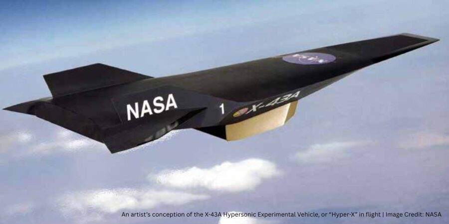
Hypersonic missiles and vehicles are an emerging class of aerospace technology that is developing rapidly toward active use in military and potentially commercial applications. These machines can achieve sustained speeds of Mach 5 or greater within the Earth’s atmosphere (i.e., at altitudes below about 90 km). While conventional intercontinental ballistic missiles can also achieve hypersonic speeds during atmospheric reentry, they follow a high-arching ballistic trajectory with limited maneuverability, in contrast to the real-time in-flight maneuverability offered by hypersonic systems. As such, military actors prefer hypersonic missiles for precision strikes (Mesa 2024), while in the commercial realm, airliners are excited by the possibility of drastically shortened journey durations with hypersonic vehicles (TomorrowDesk 2025).
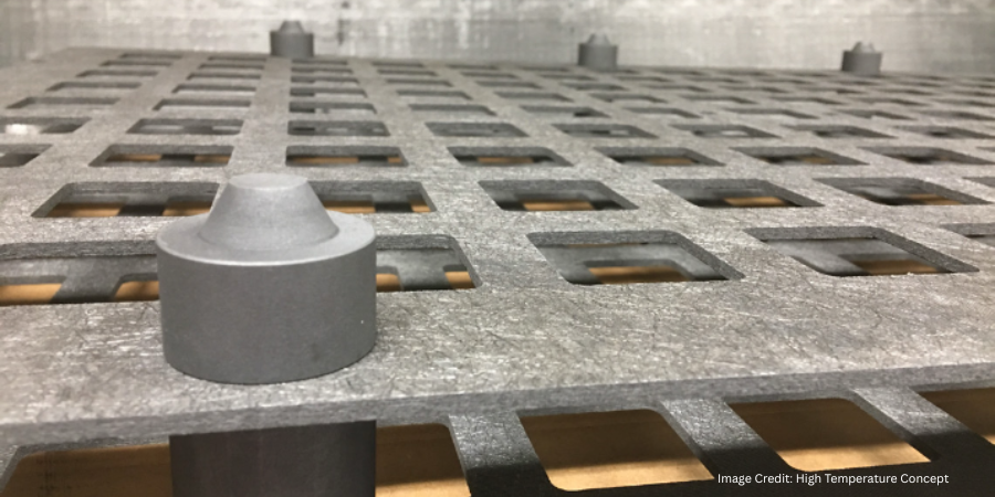
Because hypersonic missiles and vehicles move at extreme speeds within Earth’s atmosphere, they are subject to significant atmospheric compression and friction effects (Smith 2021). These effects result in considerable aerodynamic heating of the leading edges, nose tips, and exhaust-washed structures, from 1800°C (3200°F) to more than 3000°C (5400°F).
Traditional aerospace materials such as aluminum, stainless steel, and titanium cannot be used at these elevated temperatures without thermal protection engineering. In contrast, an emerging portfolio of materials including refractory metals, carbon-carbon composites, ultrahigh-temperature ceramics (UHTCs), and ceramic matrix composites (CMCs) can more easily deal with this extreme heat.
UHTCs and CMC materials typically are composed of metal carbides, borides, and nitrides, which means they are traditionally processed at very high temperatures. Currently, the leading candidate materials are silicon carbide (melting/decomposition point: 2730°C, or 4945°F) and zirconium diboride (melting point: ~3246°C, or 5875°F) due in part to their reasonable raw material costs.
Processing of UHTCs, CMCs, and other advanced materials for aerospace applications includes one or more of the following high-temperature processing steps, often using vacuum and controlled atmosphere furnace technology:
- Chemical vapor infiltration
- Chemical vapor deposition
- High-temperature sintering
- Graphitization
- Silicon melt infiltration of carbon-carbon composites
Each stage of the product development cycle — from laboratory-scale research and development to prototype development to production-scale manufacturing — requires a portfolio of specialized furnaces to achieve the goals of each stage.
This article takes a closer look at the types of furnace solutions available to develop, process, and commercialize these high-performance materials.
Laboratory-Scale Research and Development
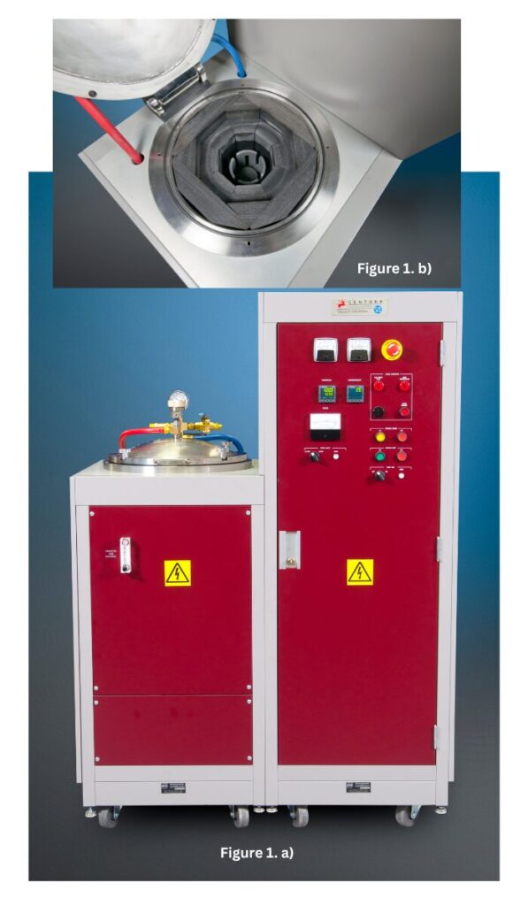
Figure 1. a) Centorr Vacuum Industries’ LF 3000°C (5400°F) graphite vacuum furnace and b) top view of hot zone; 3” x 4” (75 x 100 mm; Ø x h) hot zone. | Image Credit: Centorr Vacuum Industries
Laboratory-scale R&D activities focus mostly on the development, fabrication, and testing of small-scale parts, which require a small, adaptable furnace.
The LF graphite vacuum furnace is an example of the type of furnaces needed for small-scale parts (Figure 1). First designed in 2012, it is a robust, low-cost development furnace with temperature capability up to 3000°C (5400°F) in vacuum or inert gas. This temperature range covers most hypersonic, UHTC, and other applications. For example, current users fit the small 3″ x 4″ (75 x 100 mm; Ø x h) hot zone with small graphite crucibles to fire graphite-based powders for applications in battery and electric vehicle technology.
In another case, Dalhousie University in Nova Scotia, Canada, a research-based university, modified the base LF system by adding a small binder/off-gassing trap and positive pressure exhaust tower for processing of non-oxide ceramics produced by additive manufacturing. These samples include silicon-based ceramics (silicon carbide and silicon nitride), high-entropy ceramics, and cermet systems.
Subsequent laboratory applications require a larger hot zone furnace for processing bigger samples. One example of this type of furnace is the Series 10 graphite tube furnace (Figure 2). This tube furnace is based on a more than 50-year-old furnace design, although the traditional alumina or quartz tube has since been replaced with a solid graphite tube. Operating in vacuum or partial/positive pressures of argon, R&D centers use this furnace to process carbon powder formulations to maximize the percent conversion to graphite, as not all carbon-based starting materials will convert to crystalline graphite.
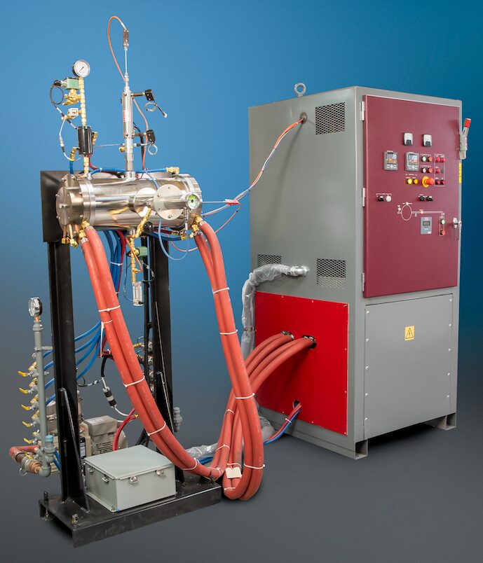
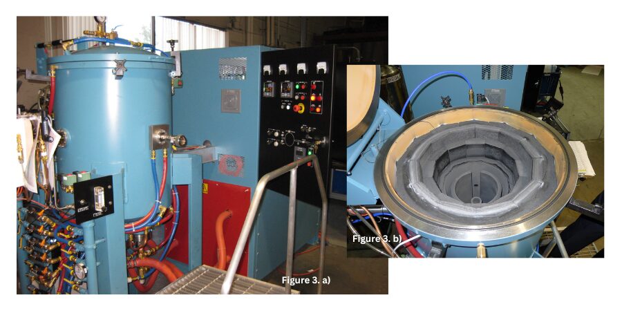
Figure 3. a) Series 45 graphite top-loading furnace and b) top view of hot zone. Used for carbon/graphite work, this model offers a larger useable firing footprint at higher temperatures than the Series 10 furnace. The hot zone diameter and height dimensions approximate 6″ x 6″ (150 mm x 150 mm), and temperature is rated for 3200°C (5790°F). | Image Credit: Centorr Vacuum Industries
As R&D activities begin to focus on particular material compositions, larger furnaces are needed to synthesize meaningful sizes and quantities of candidate materials prior to scaling up for manufacture, like the Series 45 graphite top-loading furnace (Figure 3).
Characterization and Prototyping Stage
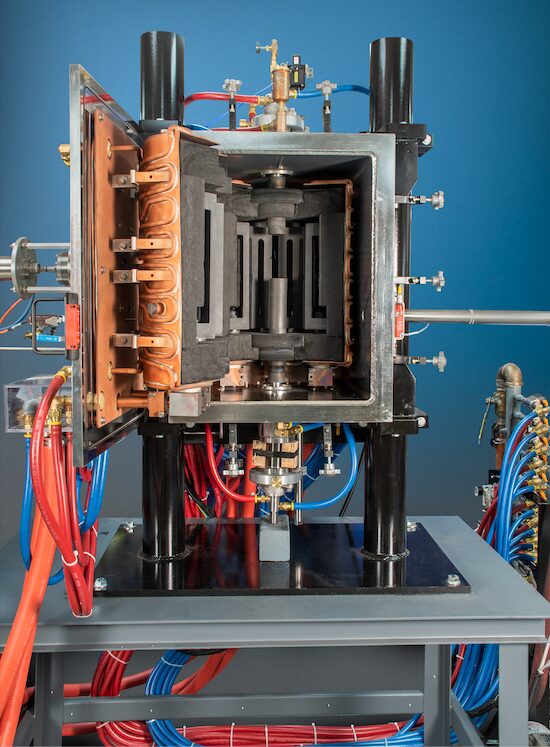
Figure 4. Front view of the Series TT Testorr graphite hot zone rated for 2700°C (4890°F) processing temperatures | Image Credit: Centorr Vacuum Industries
Once the final candidate materials are processed, aerospace design engineers need to test meaningfully sized samples of the materials at high temperature under mechanical loading. It is best to have a furnace that can be combined with mechanical test stands to take measurements of mechanical properties. This is the case for Wichita State University’s National Institute for Aviation Research, which leverages multiple Testorr® furnace units to measure tension, compression, and shear properties of ceramic matrix composites, refractory metals, and other materials at high temperature. Rated for temperatures up to 2700°C (4890°F) in vacuum or inert gas, the furnace can better simulate some aspects of hypersonic service environments (Figure 4).
An important task of the R&D and prototyping stages is to work out processing parameters that will be translated to production-scale manufacturing processes. For example, simple carbon structures will react with air during reentry and suffer damaging effects at temperatures as low as 500°C (930°F). Therefore, any carbon-carbon materials or solid carbon shapes used in hypersonic applications must be protected with advanced ceramic coatings for durability and oxidation resistance.
Chemical vapor deposition is one such coating deposition process, and one of the most popular protective coatings is silicon carbide. The coating is deposited on substrate parts by flowing hydrogen gas through a bubbler of liquid methyltrichlorosilane (MTS; CH3SiCl3) gas. Newer systems use a heated evaporator to vaporize the MTS liquid in a hydrogen carrier gas stream. The combination of hydrogen and MTS is introduced at partial pressures into the furnace hot zone inside a graphite retort, where the gases “crack” or decompose, depositing microns-thick coatings of silicon carbide onto the part’s surface.
Production Stage
Once the advanced materials are properly characterized and prototyped, it is time to look at equipment for full-scale production manufacturing. The furnace configurations for these processes can be conventional front-loading designs or may be oriented in vertical top- or bottom-loading designs for floor space savings and gas flow dynamics.
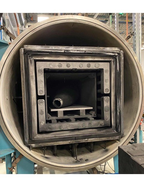
Figure 5. Production-size Sintervac vacuum furnace for processing carbon-carbon melt infiltration composite materials | Image Credit: Centorr Vacuum Industries
The Sintervac® front-loading graphite furnace (Figure 5) has integral graphite retort and dual gas flow to the main chamber and retort. These furnace systems include durable rotary piston pumping systems with inline binder traps and particulate filters to protect the pumping systems from damage from abrasive ceramic particulates. The internal graphite retort compartmentalizes the off-gassing that takes place and prevents it from escaping into the hot zone, where the oxide byproducts can attack and degrade the graphite heating elements and rigid graphite board insulation.
One common application for this type of furnace is melt infiltration of carbon-carbon composites to improve the physical properties and oxidation resistance of the composite. When processed in partial pressures (or even at positive pressures) of argon, silicon will melt at approximately 1450°C (2640°F). The silicon liquid and vapor infiltrate into the void spaces of the porous carbon-carbon composite via capillary action. The infiltrated silicon reacts with the free carbon in the carbon-carbon fiber structure, forming a silicon carbide matrix around the carbon-carbon fiber structure.
Firms like Exothermics (Amherst, NH) use this process for missile and aerospace applications. The silicon carbide matrix structure provides an environmental barrier to oxidation during reentry into Earth’s atmosphere and improves the matrix’s temperature performance to approximately 1600°C (2910°F) in air.
Smaller production units were also developed for carbon-carbon work at temperatures from 2450°C and 2600°C (4440°F and 4710°F). The addition of dedicated water-cooled filtration traps and 10-μ particulate filters helps deal with the heavy off-gassing expected from processing of carbon-carbon materials.
In contrast to melt infiltration, chemical vapor infiltration drives gaseous reactants into the porous matrix where the gas reacts with the porous structure to form a dense matrix. The chemical vapor infiltration process is used to fabricate larger parts for hypersonic applications, such as rocket motors and missile components, and carbon-carbon aircraft brakes. Vertical top- and bottom-loading chemical vapor infiltration units like the example in Figure 6 can be used for these types of applications.
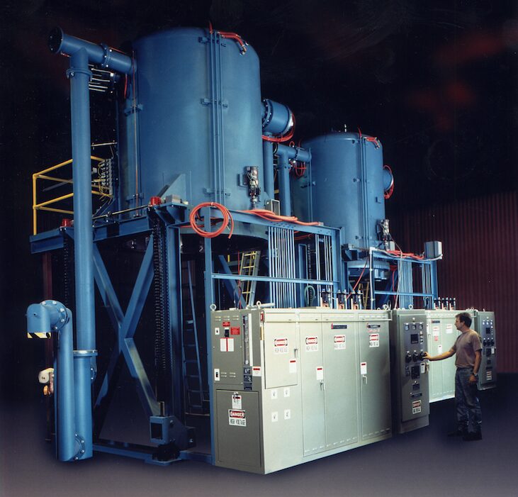
Figure 6. Series 4300 vacuum furnace for chemical vapor infiltration and graphitization. The furnace may be built in a top-loading or bottom-loading configuration; the unit scales from 52″ to 80″ (1,320 mm to 2,000 mm) in diameter and heights from 80″ up to 120″ (2.0 to 3.0 meters). | Image Credit: Centorr Vacuum Industries
In the chemical vapor infiltration process, gases, including hydrogen, methane, and propane, are fed into the furnace chamber at high flow rates and at temperatures approaching 1000°C–1100°C (1830°F–2010°F). The methane and propane gases break down and deposit carbon deep into the matrix of the carbon-carbon fibrous parts. These cycles can be very long, approaching seven to ten days, for the material to fully densify, and multiple cycles are usually necessary.
Low operating pressures require extremely large mechanical pumping systems with large vacuum blowers or boosters. These furnaces include water-cooled “tar” traps (with a heated stripping system) and large Dollinger particulate filters for handling the resin off-gas byproducts.
These furnaces are almost always induction heated, using multizone induction coils and large, thick-wall graphite susceptors for optimal temperature uniformity. The insulation design uses carbon black powder, which is economical and highly efficient for temperature reduction.
While more conventional rigid or flexible graphite board or felt materials can be used, Centorr’s experience has shown that the degree of infiltration of carbon resins over time will affect the density and porosity of the insulation pack (as it does the load material), causing degradation and densification of the insulation. The denser insulation results in high coil water temperatures, which compromises hot zone life. Specialized carbon black installation and removal equipment is required by the end-user to maintain the insulation efficiency of the furnace hot zone. Because gas flow in the furnace is critically important, special diffusor plates or plenums are used to uniformly direct gas flow across the entire geometry of the parts.
Once the advanced materials undergo chemical vapor infiltration, they are still composed of a carbon base material, which needs to be converted to a more orderly crystalline graphite structure to impart the durability and strength required in aerospace applications. To accomplish this conversion, the material needs to be heated at temperatures greater than 2300°C (4170°F), a process called graphitization.
The graphitization process employs similar furnace designs to the chemical vapor infiltration process, but the induction heating power supply is changed to the more conventional single zone coil, and the vacuum pumping systems are smaller with no tar traps needed. Load sizes of 3,000–5,000 lb. (1,360–2,268 kgs) are possible. Both the smaller and larger chemical vapor infiltration and graphitization units have large, water-cooled heat exchangers inline with large cooling fans, which reduce cooling times from ten or more days to less than 175 hours.
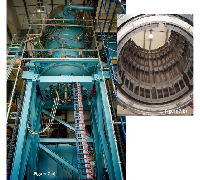
Figure 7. a) Series 3800 bottom-loading silicon carbide chemical vapor deposition furnace. b) Series 3800 chemical vapor deposition furnace hot zone with multizone control; 53″ diameter x 83″ height (1,350 mm x 2,108 mm) graphite hot zone furnace rated for 1600°C (2910°F) operation. | Image Credit: Centorr Vacuum Industries
A smaller graphitization unit was also developed in a 30″ diameter x 40″ height (76 mm x 1,000 mm) size rated to 2900°C (5250°F) maximum temperature in a vertical bottom-loading configuration for processing smaller parts in lower volumes for aerospace brakes.
The silicon carbide chemical vapor deposition units for laboratory applications discussed previously are also needed for production-size volumes (Figure 7). Due to tight temperature uniformity requirements, these units are multizone control with graphite hot zones constructed of rigid graphite board for process durability. The pumping systems can be either “dry” or “liquid ring” designs for processing the acidic off-gas materials. A post-exhaust chemical scrubber system is required to safely neutralize the hydrogen chloride off-gases.
Enabling the Next Generation of Aerospace Materials
The difficult design requirements of next-generation aerospace technologies will continue to push the existing limits of material performance. As characterization and development of new materials will be critical to the success of these aerospace programs, vacuum and controlled atmosphere furnaces will play an essential role in the production of such materials.
References
American Elements. n.d.a “Silicon Carbide Data Sheet.” https://www.americanelements.com/silicon-carbide-409-21-2.
American Elements. n.d.b “Zirconium Diboride Data Sheet.” https://www.americanelements.com/zirconium-diboride-12045-64-6.
Mesa, J. 2024. “What’s the Difference Between a Hypersonic Missile and ICBM?” Newsweek, November 21, 2024. https://www.newsweek.com/difference-between-icbm-irbm-missiles-1989780.
Smith, C. R. 2021. “Aerodynamic Heating in Hypersonic Flows.” Physics Today 74 (11): 66–67.
TomorrowDesk. 2025. “Hyperian Aerospace and the Dawn of Hypersonic Flight.” TomorrowDesk, March 29, 2025. https://tomorrowdesk.com/evolution/hyperian-aerospace-hypersonic-flight.
Heat Treat Today thanks the American Ceramic Society for allowing us to print this piece. This article was originally published in ACerS Bulletin, September 2025.
About The Author:

Product Manager of Ceramics and Powder Metallurgy
Centorr Vacuum Industries
Scott K. Robinson is product manager of ceramics and powder metallurgy at Centorr Vacuum Industries (Nashua, NH).
For more information: Contact Scott Robinson at srobinson@centorr.com.