The monthly Industrial Heating Equipment Association (IHEA) Executive EconomicSummary released in October investigates the role politics takes in the economy. At this time of the year, thoughts turn to elections, with the economy discussed throughout the nation. What can politicians really do to change the course of the nation's economy? The IHEA report shares a hope for 2023 and some thoughts on what politicians could do to encourage this growth.
The nation's economy spreads over diverse sectors. It's difficult to point to one area to explain the cause of the recession. Some, like the aerospace and automotive, are seeing positive growth. Other areas, like electronics and machinery, are still in a downturn. The report states, "The expectation is that GDP will expand by a very anemic 0.3% in Q3 and this will be followed by another two quarters of GDP decline (0.5% in Q4 and another 0.5% in Q1 of 2023)." After this, if the estimates play out, 2023 will see the economy growing by the end of year. Forecasts suggest that Q2 of 2023 will see small, albeit positive, growth; while Q3 and Q4 suggest significant moves to the positive.
People are holding back on spending, wanting to save something for an uncertain future. They are thinking about their jobs and are concerned for household budgets. If they could be motivated to spend, that will help the economy with substantial growth in 2023. Politicians can do something about this, according to the report.
How can the political sector make an impact? "The most useful thing the politician could do now would be to reassure the population so that there would be the kind of spending that pulls an economy out of a downturn," explains the report. "There could be significant encouragement for the process of reshoring or attention paid to worker shortage or infrastructure development." According to the report this isn't happening. It doesn't seem like the politicians are interested in taking this approach.
Anne Goyer, Executive Director of IHEA
Check out the full report to see specific index growth and analysis which is available to IHEA member companies. For membership information, and a full copy of the 11-page report, contact Anne Goyer, executive director of the Industrial Heating Equipment Association (IHEA). Email Anne by clicking here.
Fundamentals of furnace maintenance sometimes fall between that tricky area of realizing their importance and getting pushed to the end of the to-do list. This original content piece shares tips to bring the fundamentals back to where they belong: at the top of the to-do list.
Ben Gasbarre President, Industrial Furnace Systems Gasbarre Thermal Processing Systems
Safety First | Whether the furnace is in operation, or it is having down time, proper safety measures must be in place. Personal protective equipment, proper shut down of power sources, and even the buddy system are topics taken in to consideration.
Asset Management System | Have up-to-date maintenance records available to any and all employees. "Ensuring important information, such as alloy replacements, burner tuning, or control calibration information, can help operations and maintenance personnel as they plan and assess future equipment needs," comments Ben Gasbarre, president industrial furnace systems at Gasbarre Thermal Processing Systems.
Cleaning | Reminders include: change filters on combustion blowers, clean things like burners and flame curtains, clean out endothermic gas lines, burn off manual probes at least once a week, etc.
Daniel Hill, PE Sales Engineer AFC-Holcroft Source: AFC-Holcroft
Rules and Regulations | The military and energy industries are sectors that have strict standards to follow. Different heat treating shops are using a software module to maintain furnace data, looking at data reports to make sure the furnace systems are running properly.
Timely Maintenance | Making a maintenance plan and then following it means that no tasks are overlooked or forgotten.
After Repairs and Adjustment | Make sure that after trouble shooting and performing repairs, the software generated reports are examined and that furnaces continue to be maintained. Daniel Hill, PE, sales engineer at AFC-Holcroft says, "This saves valuable time and resources, improves availability, and likely increases profitability."
Greg Steiger Senior Key Account Manager Idemitsu Lubricants America
Proper Levels of Sludge and Water Quench | Failing to keep the quench oil clean results in problems on surface finish. Maintain the quench from the start by filtering, cleaning, and replenishing to keep end product surfaces more acceptable.
Frequency of Sampling | "[The] more often a quench oil is analyzed, the easier it is to use the quench oil analysis as a tool in the proper care of a quench oil," explains Greg Steiger, senior key account manager at Idemitsu Lubricants America.
Regular Addition of Fresh Oil | Proper maintenance of quench oil will result in some loss through filtration. Be sure to replenish.
Find heat treating products and services when you search on Heat Treat Buyers Guide.com
Heat Treat Todayis launching a How Things Work periodic content series. The first topic is the basics of thermocouples. Thermocouples are the bread and butter of the heat treating world. How many of the following questions are news to you? Take a deep dive into the topic and read this question and answer session between Doug Glenn, publisher and founder ofHeat Treat Today, and Eric Yeager, director of Corporate Quality at Cleveland Electric Laboratories.
This Technical Tuesday discussion on thermocouple basics will be published inHeat Treat Today'sNovember 2022 Vacuum Heat Treating digital edition.
What is a thermocouple?
Doug Glenn (DG): In this industry, and I suppose in a lot of industries, they often refer to thermocouples as T/Cs.
Let’s start off with one of the very most basic questions: What is a thermocouple?
Eric Yeager (EY): A thermocouple is a device that measures temperature. It contains no moving parts, has no power source and it does not contain any hazardous materials like liquid mercury or anything like that.
DG: Right. That’s interesting you say that, and it’s actually good that you say that, because some of our residential consumer thermometers (which a thermocouple is kind of like a thermometer in one sense) do have hazardous materials like mercury.
EY: Absolutely, absolutely.
How does a thermocouple tell temperature?
DG: So, there are no moving parts or anything of that sort. How, exactly, does a thermocouple tell the temperature?
EY: All metals that exist, when introduced to a temperature gradient (so, if you had the length of metal A and you introduce it to a temperature gradient, which would be a difference from one end to the other) will produce a microvoltage. That microvoltage is the potential that is known as the "absolute Seebeck effect" and that’s the basis on which the single thermocouple element functions.
DG: So, when you say the single thermocouple element, what do you mean by that?
Eric Yeager Director of Corporate Quality Cleveland Electric Laboratories
EY: That would be one leg — either your positive leg or your negative leg — or it could be any actual wire that exists, and as long as you introduce a temperature gradient, it will produce some microvoltage. With thermocouples, there are set standards for what those materials are manufactured from, but any wire will create a microvoltage or an EMF output.
DG: So, let’s say we took a copper wire from our house, and we put one end on top of a candle (just for heat’s sake); you’re saying that within the span of that wire, there is going to be a voltage of some sort.
EY: Correct. And that’s actually called the "absolute Seebeck effect" or EMF.
DG: EMF, electromotive force. And Seebeck, if I understand correctly, he was the guy that discovered this stuff, right?
EY: He’s one of them. Peltier was involved and I think a gentleman named Thompson. But it was all around the same time — they kind of all collaborated with one another.
DG: You mentioned, with a thermocouple, if you have a section of wire material, add heat to one end, there’s going to be a voltage of some sort, a millivoltage in this case, a very small voltage, but a voltage, nonetheless. But you mentioned one leg. Explain more about the one leg; because, typically, isn’t there just one piece of wire in there?
EY: Right, correct. A thermocouple consists of two dissimilar metals, two dissimilar wires. For example, in a type K thermocouple, one leg would be chromel and the other leg would be alumel, and when you join those two dissimilar metals together, the net voltage between the two combined dissimilar metals is what is used to measure the output of the thermocouple. [blockquote author="Eric Yeager" style="1"]This conversion of thermal energy to electrical energy is known as the Seebeck effect.[/blockquote]
DG: So, let’s say you stick a piece of copper wire over a candle that’s burning at 400 degrees, or whatever the candle might be burning at, you’re going to get a certain voltage across there or within the wire.
EY: Along the length of that wire, yes.
DG: So, if the temperature of that candle is twice the temperature (let’s say you double the temperature of the candle) the voltage across the length of that wire is now different, yes?
EY: It’s proportional. So, the greater amount of heat energy you apply, the greater amount of EMF will be generated.
DG: And that wire, typically, for the useful life of the wire, does not change? It’s always the same? If it’s at a 100 or 1000 °F, that voltage is one; if it’s 2000, it’s that; it doesn’t ever dissipate over time, does it?
EY: No. It only degrades when a contaminate is introduced to the material.
DG: Gotcha. Because it then prevents the flow, I assume.
EY: Correct. And it’s not as pure. So, that’s one of the effects as you see something that’s called "drift" over time, over use.
Why do dissimilar materials/metals produce a millivolt signal?
DG: Now, you said, though, that in a type K, and I know that in almost all thermocouples we’ve got two dissimilar metals. If one wire can tell you an output of the voltage, why do you need two dissimilar metals in order to get a different type of voltage?
EY: It’s basically the sum of the two materials; combine the voltage generated from the entire length of the wire of the two thermal conductors.
You have to have a signal path. You have to have a source for your voltage to start and a voltage for it to end into your instrumentation. You have to have some way to read that temperature gradient and it’s typically done with two dissimilar metals to create a greater and more stable EMF.
When a lot of the cable or wire manufacturers create, say, a melt of chromel, they test that, and actually test it against a pure platinum wire so as to return the voltage back to the instrument to measure the actual EMF for the single leg output.
How important is the joining of these dissimilar metals?
DG: Now, you talked about the joining of the two dissimilar metals. How exactly how does that need to be done? Can they be welded together, and if they’re welded together, doesn’t the metal that’s used in the weld mess it up? And does it have to be just at a point, or can it be along a length that they are joined together?
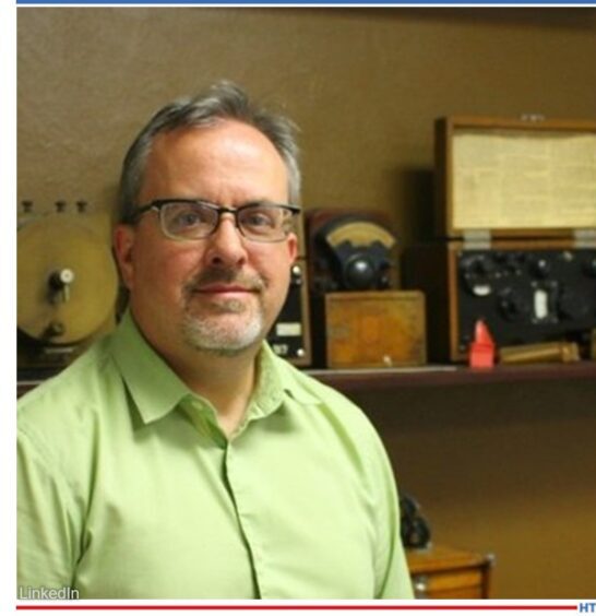
Eric Yeager Source: LinkedIn
EY: It’s important to have the purest, most secure junction when joining the two dissimilar metals. It’s typically done by welding the metals together without adding any filler material. That’s especially important when you have something that has a very low EMF output, which is like your noble metal thermocouples. That’s where purity is essential. Loose connections from twisted or crimped junctions also might cause intermittencies under thermal expansion and affect the thermocouple output signal.
DG: So, typically, they are welded together without a filler; they’re just welded together.
EY: Correct. You just bring a TIG torch in, give it a quick zap, and it melts the two wires together. Once you get that nice little joint or junction, you can run and complete the assembly.
DG: Okay. We already talked about why there are different millivolt readings at different temperatures, because basically it’s the difference in the heat.
EY: Correct. As the temperature increases, there’s a direct correlation to the microvoltage output from that particular wire or wire pair.
DG: And I asked about how important are the joining of these materials. Typically, you don’t want it over a wide section, right? Does it matter if it’s a spot weld, instead? What would happen if you had one that was an inch or two inches long? Is that a big deal?
EY: It’s best to keep it as small and concise as possible, because it could form a heat sink later on when you’re in application; typically you just want a small nice round junction. For example, you want the junction to be about twice the diameter of the single thermal element. So, if it was a 20 thousandths-diameter wire, you want it 40 thousandths in diameter.
Thermocouples welded to a workload; wouldn’t that weld introduce some “interference” in the millivolt signal?
DG: Aren’t some T/Cs welded? I think I’ve heard that sometimes they’ll take thermocouple wire that will be joined and then welded to, or in some way applied right to, a load. If you were applying it directly to a workload, wouldn't that extra metal kind of mess up the millivolt?
EY: You would think so, but as long as they’re kept as close as possible, and the workpiece that you’re welding to is kept isothermal or actually uniform in temperature between the two welded junctions, it won’t have a detrimental effect on the thermoelectric output. [blocktext align="right"]But you want to make sure that the workpiece is uniform in temperature because you have a temperature gradient across where those two junctions are welded to the material, and it can have a slight effect.[/blocktext] That’s essential to basically ensure that your workpiece is isothermal.
DG: What do you mean by isothermal?
EY: Uniform in temperature across the entire workpiece between the welded beads. The workpiece will become the welded bead, but it won’t create any additional EMF output to the combination because it’s the combination of the length — it measures the temperature across the entire length of the wire not necessarily at the bead.
It’s kind of a common misconception that the bead creates all the EMF, but it’s actually along the length of the wire.
DG: It is along the length of the wire. I always thought that the temperature was measured basically at the bead, at the joint.
EY: Well, that’s where it starts, but it’s combined along the length of the wire.
In the heat treating world, what is the most popular T/C and what are the materials from which it is made?
DG: So, in the heat treat world, what’s the most popular T/C and what are the materials it’s made from?
EY: I would say it’s definitely the type K and those two materials are chromel and alumel as we previously discussed. It’s probably the most popular due to the low cost and the wide temperature range capability. Basically, you can go from 32°F all the way up to 2450°F. It won’t last very long at those temperatures, but it’s the most common and the most versatile. I would say type K is the most popular.
How long do type K thermocouples last in a furnace/application?
DG: The factors: you were talking about them not lasting all that long. This is probably a loaded question, but if you’re in an average heat treat application, what’s a typical lifespan of a type K?
EY: To be honest with you, that’s the question that everybody wants to know. And truthfully, it depends on the application. It depends on thermal cycling, it depends on how well the thermocouple thermoelements are protected from the environment, for example, whatever protection tube you put it in, if it’s an MGO, or an exposed bead. All of those things are contributing factors. Really, it’s very, very application dependent. For example, I’ve seen type K control thermocouples last for 5 years but that’s basically at a stable temperature without any thermocycling and a constant, nice, clean environment. But I’ve seen units that get consumed rapidly at the elevated temperatures, like I mentioned, 2450°F. They don’t last very long there but they do measure.
DG: So, the undesirable conditions for those things would be a lot of thermocycling up and down, so, it’s going to fail faster, I assume?
EY: Correct. And temperature of course: the higher temperature, the greater degradation in the material. That pretty much stands for any thermocouple type.
DG: I want to ask a couple questions that aren’t on here just because I’m curious about this. A lot of times, you’ll have the spot weld where you put them together, that’s called the bead?
EY: Yes. Or junction. Either/or.
DG: So, the bead or the junction — that’s obviously bare wire, right? Assuming we’re actually using to put it on a workpiece. You’ve got the bead and then you’ve got, obviously, a little bit of bare wire at least. Is the rest of that wire covered or is it often not covered?
EY: It must be covered because it could short somewhere along the length of the wire. It could be either a soft wire insulation, like a ceramic fiber or a REFRASIL® or even a fiberglass-type insulation depending upon the temperatures.[blockquote author="Eric Yeager" style="1"]What I actually prefer is an MGO-style thermocouple where it has a metallic outer sheath surrounded by a magnesium oxide insulator that prevents it from shorting out.[/blockquote] So, for example, if you just ran straight wire and had any kind of airflow or thermal expansion, it could short out somewhere along the length of the wire. Basically, a thermocouple will measure from the closest measuring junction to the instrumentation. Therefore, if it’s shorted out, you’d get a false reading.
DG: So, if you had it attached to the load and it runs over here but it touches something else just before it goes out to the outside of the furnace or whatever, you’re going to measure that spot closest to the temperature wall, so it doesn’t give you anything on the load.
EY: What’s very common is people will run the software thermocouples through a door of a furnace where it closes on the door, that’s where it shorts out.
What are some of the factors that will affect the longevity of a T/C? What is the most common cause of failure?
DG: What are the most common causes of failure? Did you have any others besides that we just talked about the door one?
EY: For control thermocouples, like your type R, S, or B, those are subject to contaminates more than the other types. They’re more susceptible to carbon, graphite, silica, and those type of things. So, when you have an assembly like that, like a control thermocouple in a furnace, you have to ensure that it’s properly protected from the environment to which it’s exposed to allow it to have the greatest longevity. There are different sheath materials that you can put the thermocouples in: alumina, it could be silicon carbide tubes, all kinds of different varieties.
DG: You want to keep the environment, the atmosphere out of it and all that good stuff.
EY: Real quick, Doug: You mentioned control thermocouples. If you had like a type R or S control thermocouple and it was exposed to something that was going to contaminate it, what typically happens when a thermocouple fails? The EMF output of the thermocouple is degraded. What that would actually cause is it would cause your furnace to call for more heat because the EMF was degraded. Even if it’s a few degrees, that might cause an overtemp condition when you have very tight requirements on a thermal process.
DG: Right. And then, hopefully, your overtemp thermocouple would kick in and say, “Wait a minute!”
EY: Yes, that’s exactly right. Hopefully, you don’t have it set too high.
How can you tell when your T/C is going bad? Drift, etc.?
DG: How can you tell when your T/C is going bad and could you talk about drift?
EY: The best way to determine if your thermocouple is going bad is to perform regular system accuracy tests. Those tests, will allow you to track the lifecycle of the thermocouples and determine when they begin to drift and when it’s time to remove them from service. Unfortunately, when a thermocouple drifts, there is not adjustment knob on it; you can’t fix it. Once it starts going, it goes, and you just have to replace the assembly.
When thermocouples drift, they typically drift negative. They will see less of a temperature due to the contaminates getting into the material and altering the EMF output of the thermocouple. So, your control will essentially ask for more heat, and that’s where you end up having the problem. That’s why it’s essential to perform your SATs and maybe set up a little PM schedule for your system to know that you're experiencing "x" many life cycles out of the thermocouples before they fall out of your requirements, and so maybe every "x" months you have to replace the assemblies and install new ones.
Because of the drift, the best thing you can do is perform a system accuracy test with a thermocouple that has not been subject to long exposure at temperature.
Dissimilar metals and EMF?
DG: I want to go back to the two-wire thing because I don’t quite understand that. I’m not an engineer guy so see if you can explain. You’ve got the one wire that has an EMF in it, but I still don’t quite get why we use dissimilar metals to create the EMF.
EY: The summation of the voltage between the two thermocouples that provides the set EMF. The set EMF, is determined by the international temperature scale ITS-90 scale; that sets all the microvoltages for the thermocouples. It’s designed as a paired thermocouple group not as a single element. With a single element, you really would not have a good way to return the signal to your instrument.
Both wires conduct the voltage back to the instrument; one is a positive and one is a negative. Since it is a direct current (DC) voltage, one leg provides the negative path and one leg provides the positive path.
DG: Ok, so there’s a millivoltage signal being sent back to the instrument, which is reading that millivolt and then converting it based on what type of thermocouple is out there; and it’s recording that reading and turning it into a temperature.
About our expert:
Eric Yeager is the director of Corporate Quality at Cleveland Electric Laboratories. He's been with Cleveland Electric Labs for 17 years and is working on year 18. In that time, he has been director of quality and runs their accredited thermocouple calibration laboratory. Eric is involved with ASTM and is a subcommittee chairman for E2011, which is the calibration section of the thermocouple standards. He also was technical consultant on some of the rewrite of the latest AMS2750.
Find heat treating products and services when you search on Heat Treat Buyers Guide.com
Governor Tom Wolf announced that Gasbarre Products, Inc., an industrial heat treat furnace manufacturer, will create and retain 172 total jobs in multiple Pennsylvania counties as part of a planned expansion at the company’s facility in St. Marys, Elk County.
Gasbarre Products, Inc. has leased a 150,000-square-foot facility at 835 Washington Street in St. Marys. The company also plans to relocate operations from their Plymouth, Michigan, location to this new facility.
Alex Gasbarre CEO Gasbarre Products Source: LinkedIn
“Our investment in the new facility in St. Marys provides an opportunity for Gasbarre to continue to grow and flourish where we have manufactured for nearly 50 years,” said AlexGasbarre, CEO of Gasbarre. “We look forward to adding new team members in the coming months when the move process is completed. The people of Elk County and St. Marys will be key to our success.”
Tom Wolf Governor Pennsylvania Source: governor.pa.gov
“My administration remains committed to investing in businesses that want to grow here or set up shop in Pennsylvania,” said Gov. Wolf. “Gasbarre is creating and retaining good paying jobs in some of our rural counties and helping to boost our competitive manufacturing industry – a true win for the commonwealth.”
Find heat treating products and services when you search on Heat Treat Buyers Guide.com
Sometimes our editors find items that are not exactly "heat treat" but do deal with interesting developments in one of our key markets: aerospace, automotive, medical, energy, or general manufacturing. To celebrate getting to the “fringe” of the weekend, Heat TreatToday presents today’s Heat Treat Fringe Friday press release: an agreement for the supply of a direct reduction system for ArcelorMittal Dofasco, in North America.
ArcelorMittal Dofasco chooses Tenova for the supply of a hydrogen-ready 2,500,000 tons/year ENERGIRON® direct reduction system, to be located in Hamilton, Canada. This system will be incorporated in the decarbonization plan through a direct reduced iron (DRI) program.
Ron Bedard President & CEO ArcelorMittal Source: LinkedIn
"While [the project] involves installing new technology and equipment, the investment is really about people and planet," explains Ron Bedard, president and CEO of ArcelorMittal. "It will help our customers lower their carbon footprint, ensuring they deliver low carbon products to consumers. It will create and protect green careers in advanced manufacturing here at Dofasco. It will improve the work environment for our operations, maintenance, and technology teams. And it will significantly reduce the environmental impact of steelmaking in Hamilton.”
The manufacturer will transition away from the blast furnace (basic oxygen furnace steelmaking production route) to the DRI-electric arc furnace production route. The technology has the capability to capture and use CO2, reducing overall CO2 emissions and providing an additional revenue stream for the system operations. The system will produce hot DRI pellets that will be processed via the proven HYTEMP, a pneumatic transport system, to a new EAF mill to be located next to the ENERGIRON® system.
Stefano Maggiolino President & CEO Tenova HYL Source: LinkedIn
“This innovative direct reduction plant will help ArcelorMittal to reach its target of reducing carbon emission and Tenova is very proud to be part of this journey.” said Stefano Maggiolino, president and CEO at Tenova HYL.
Find heat treating products and services when you search on Heat Treat Buyers Guide.com
The powder metal industry continues to develop to keep up with production and industry needs. What exactly goes on with powdered metals and additive manufacturing? What is the sintering process? What should heat treaters know about the future of this industry?
In this original content article, three different resources -- an article, a radio broadcast, and a Heat TreatTVepisode -- come together to answer these questions and much more.
Ron Beltz Director of Strategic Accounts Bluestreak | Bright AM™
In this article, investigate the processes used to treat the metal powders. Sintering is one such process and others, like annealing and hot isostatic pressing, are examined too. Ron Beltz, director of strategic accounts at Bluestreak | Bright AM’s™ takes a look at these processes and also discusses other elements like software use and serialization. "One of the issues of additive manufacturing is the possibility of internal defects," Beltz explains. "Direct metal laser sintering (DMLS) regularly produces near 100% dense parts, but to provide another level of control to help reduce part failure, hot isostatic pressing (HIP), instead of heat treating, is successfully being used by many aerospace companies and in the casting industry."
Harb Nayar TAT Technologies (photo source: tat-tech.com)
Hear from Harb Nayar, president and CEO, TAT Technologies; as he peers into the future of the industry; "The other [change in industry] I think that’s going to emerge is most probably making more and more parts by powder metallurgy from metal powder which are 100% free alloyed." Nayar is confident that the powder metal industry will keep growing, and this interview gives good insights from his depth of knowledge.
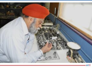
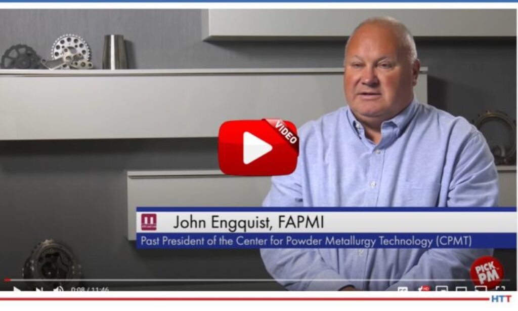
John Engquist,FAPMI (past president of the Center for Powder Metallurgy Technology), gives some practical basics on what powder metallurgy (PM) is and how sintering helps produce automotive components. "Let's take a look at some PM applications: here we have a notch and pocket plate that are used in one way clutches. . . .made from sinter hardened steel and iron carbon steel. Here we have an automotive planetary carrier system. . . .Here we see stator cores for electric motors . . . ." Listen in on ways to use powdered metal.
These thought-provoking pieces give an opportunity dig a little deeper into sintering and additive manufacturing. Stay on top of education and developments within the powder metal industry.
Find heat treating products and services when you search on Heat Treat Buyers Guide.com
It's always a good idea to review the building blocks of the heat treat industry. In preparation for Heat TreatBoot Camp, get back to the basics to be ready for these five topics: Products, Processes, Players, Markets, and Materials. Take a look or listen to any of these 10 resources in this Technical Tuesday original content compilation to be geared up for Heat TreatBoot Camp.
See you in Pittsburgh on October 31st!
Products
Here's a look at one type of product that is used in heat treatment processes: a mesh belt heat treatment system. This article takes a look at advancements in improving fastener quality:
Learn how nitriding and ferritic nitrocarburizing processes differ in this in-depth article. Keep it simple by referring to the easy-to-understand chart within the piece:
The aerospace, automotive, energy, and medical markets are constantly evolving and improving. Just to keep the markets fresh in the mind, here is the latest technical item from each:
Maciej Korecki Vice President of Business of the Vacuum Furnace Segment SECO/WARWICK
The Andritz Group, a manufacturer of complete lines for cold-rolled strip production and processing, has ordered a vertical vacuum furnace. The furnace for gas quenching processes will help produce consistent product quality.
SECO/WARWICK Group , a manufacturer with North American locations, equipped the Vector® furnace with a graphite chamber, gas cooling system, and a rotating hearth. The Andritz Group, with this system, adds to their heat treat capabilities in hydraulic power, pulp, and paper as well as metals processing industries.
This is the first vacuum furnace manufactured in the Tianjin facility of the SECO/WARWICK Group. “We have already worked with the Andritz Group, but this time it is the first contract with our Chinese branch. The Vector furnace is manufactured in our Chinese factory, which significantly shortens the solution’s delivery time to the customer," says Maciej Korecki, vice president of the Vacuum Products Segment at SECO/WARWICK Group.
Find heat treating products and services when you search on Heat Treat Buyers Guide.com
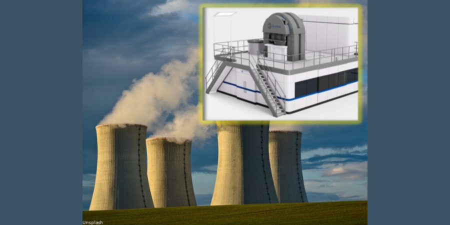
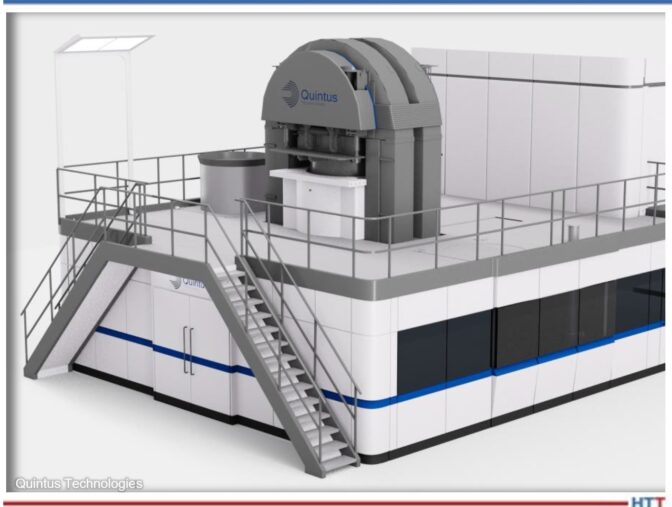
MTC Powder Solutions received a hot isostatic press (HIP) that will extend the onsite size parameters of the Powder Metallurgy Near-Net Shape (PM-NNS) HIP components for the oil and gas, chemical, nuclear, and power generation industries.
Quintus Technologies HIP System Source: Quintus Technologies
Quintus Technologies, a HIP provider with North American locations, installed the press QIH 286L M URC® to accommodate the core components for many different mission-critical applications. MTC Powder Solutions will use the system with a work zone of more than 11 ft. high to increase productivity with components, having improved fatigue strength and extended service life.
Dr. Magnus Nyström managing director MTC Powder Solutions Source: LinkedIn
“We see a lot of opportunity in the areas of renewables, civil nuclear, small nuclear reactors, and the food industry,” reveals Dr. Magnus Nyström, managing director at MTC Powder Solutions. “In many of these sectors, the projects are becoming increasingly challenging in terms of higher pressures and more corrosive environments, and there is a strong desire for implementing PM HIP where traditional manufacturing technologies such as forgings and castings fall short.”
Jan Söderström CEO Quintus Technologies
"We have seen the need for hot isostatic pressing increase steadily,” says Jan Söderström, CEO of Quintus. He continues, "The push for faster fabrication and lead times favors PM HIP technology as its freedom-of-design benefit can remove costly fabrication processes such as welds and/or machining."
Find heat treating products and services when you search on Heat Treat Buyers Guide.com
Nic Willis Metallurgist/Heat Treat Manager Emerson Professional Tools Source: DELTA H
RIDGID® TOOLS received twin furnace systems from a North American supplier. These systems will heat parts from ambient to 975°F, soak for two hours, cool to 120°F, soak two hours, and then repeat. This will increase the production capacity of the company's current operations.
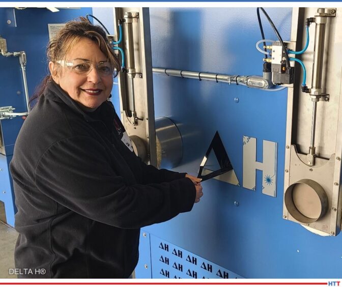
The furnaces, from DELTA H®, feature a stainless steel interior with low mass ceramic fiber insulation for minimal heat retention, are designed to receive baskets with parts from an Ipsen Titan vacuum furnace, and include a floor guide system to enable precise load placement.
Roseanne Brunello, director of Sales at DELTA H®, has the honor first revealing the company's logo. Source: DELTA H
"We had a challenge with utilization of our [current] vacuum furnace where a secondary heat treatment might be better accomplished with a convection furnace," explained Nicolas (Nic) Willis, metallurgist/heat treat manager at Emerson Professional Tools, provider of RIDGID® TOOLS. "This would dramatically increase the production capacity of our vacuum furnace and fully [optimize] this process. The extreme and demanding rapid heating and cooling cycles called for a unique convection furnace design."
"I have known Nic for many years, including the Cleveland Chapter of ASM International where we both served as officers – and was honored to nominate him to the Heat Treat Today's 40 Under 40 Class of 2020," comments RosanneBrunello, director of sales at DELTA H. "The process here was a challenge, but our CTO, Richard Conway, answered the call with an innovative and unique furnace design."
Main Photo Caption: Nicolas (Nic) Willis, Metallurgist/Heat Treat Manager at RIDGID® TOOLS and Richard Conway, Director/Chief Technology Officer at DELTA H®
Find heat treating products and services when you search on Heat Treat Buyers Guide.com


 What is a thermocouple?
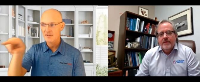 DG: Right. That’s interesting you say that, and it’s actually good that you say that, because some of our residential consumer thermometers (which a thermocouple is kind of like a thermometer in one sense) do have hazardous materials like mercury.
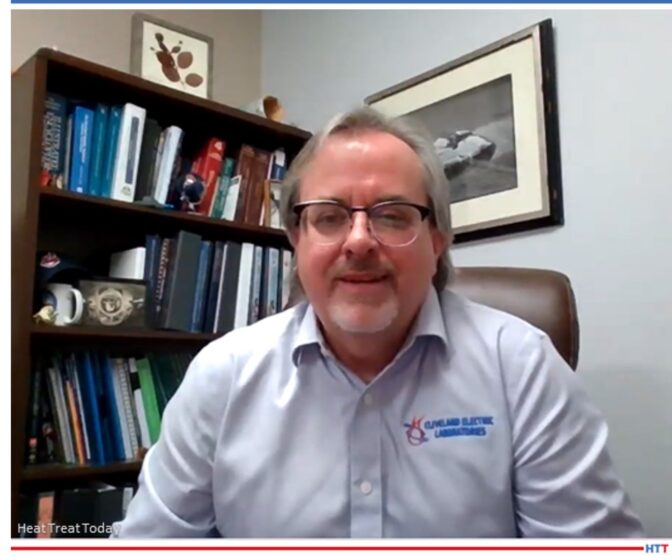

 Governor Tom Wolf announced that Gasbarre Products, Inc., an industrial heat treat furnace manufacturer, will create and retain 172 total jobs in multiple Pennsylvania counties as part of a planned expansion at the company’s facility in St. Marys, Elk County.