Technical Tuesday

Predicting the Effects of Composition Variation for Heat Treatment of Aerospace Alloys

In the following original content from Heat Treat Today, Thermo-Calc Software's Adam Hope, PhD, materials scientist, and Paul Mason,  president, delve into how modeling and simulation tools can help heat treaters make well-informed decisions.

This article first appeared in the latest edition (March 2020) of Heat Treat Today’s Aerospace Heat Treating magazine.


Consistency in material properties and performance is critical to the aerospace industry, and small variations in material chemistry or process windows can have a large impact on the final parts performance. The ability to predict and adjust for these variations can reduce scrap and part re-work. Metallurgists and process engineers responsible for heat treatments must adapt their process when input variables change, such as material chemistry. They are routinely faced with questions such as:

Paul Mason
President
Thermo-Calc Software

*How will heat to heat variations affect the final part performance?

*What heat treatment should be given to a part that has been built via a novel approach such as additive manufacturing?

*How should one optimize a heat treatment schedule for a new alloy?

*When the data required to make these decisions does not exist, what are the options?

Experiments can generate this data, but this is costly and time-consuming. Handbooks might have data for known alloys, but this is often only for the nominal composition and may not be suitable for material processed under a novel route. Modeling and simulation tools can help fill this knowledge gap and help inform better decisions.


Integrated Computational Materials Engineering and CALPHAD

Adam Hope, PhD
Materials Scientist
Thermo-Calc Software

The publication by the National Academies in 2008 on Integrated Computational Materials Engineering (ICME)[1] outlined an approach to designing products, the materials they are comprised of, and their associated materials processing methods, by linking materials models at multiple length scales. The report highlighted the need for a better understanding of how processes produce material structures, how those structures give rise to material properties, and how to select materials for a given application, describing the need for using multiscale materials modeling to capture the process, structures, properties, and performance of a material.

Computational thermodynamics, and specifically CALPHAD (CALculation of PHase Diagrams)[2], enables the prediction of the thermodynamic properties and phase stability of an alloy under stable and metastable conditions. The CALPHAD approach captures the underlying composition and temperature dependence of properties and can also be extended to model atomic mobilities and diffusivities in a similar way. By combining thermodynamic and mobility data, kinetic reactions during solidification and subsequent heat treatment processes can be simulated. Computational thermodynamics and CALPHAD- based tools are an important component of an ICME framework because, through the use of such simulations, it is possible to vary alloy compositions and predict optimal solidification processes and solution heat treatment temperature ranges without performing many time-consuming and costly experiments.

Predicting Heat Treatments for Additively Manufactured Parts

Many additive manufacturing processes subject the material to rapid solidification with multiple subsequent reheat cycles. The effect of these thermal cycles on material properties is not always known and typically does not result in the properties that a similar cast or wrought metal would have. Additionally, many additively manufactured parts are built using conventional alloys which have been engineered for cast or wrought processes. In some cases these alloys are not suitable for additive processing, and problems such as deleterious phases forming during a post-build, stress-relief heat treatment, designed for conventionally treated alloys, may result.

Additive processes are typically associated with rapid cooling rates and large thermal gradients. This can give rise to the following:

  1. High levels of residual stress in the final part
  2. Microsegregation during solidification of each layer, which leads to local inhomogeneities in alloy composition

In the case of additive manufacturing, these separate heat treatments are often combined, and stress relief heat treatments designed for cast or wrought material may not be suitable for additively processed materials for two reasons:

  1. The chemical inhomogeneities arising from rapid cooling can influence precipitation behavior, and some deleterious precipitates may precipitate more quickly than expected.
  2. The multiple heating cycles of subsequent layers may have already started some precipitation reactions, making stress relief more difficult without first homogenizing these precipitates.

Zhang et al.[3] have studied laser powder bed builds of Alloy 625 and found that after applying an industry recommended stress relief heat treatment, delta phase can precipitate in the segregated regions much faster than in the wrought material. The formation of delta phase is extremely detrimental to material properties. They attributed this to increased Nb and Mo concentrations found in the interdendritic regions in the as-built microstructure.

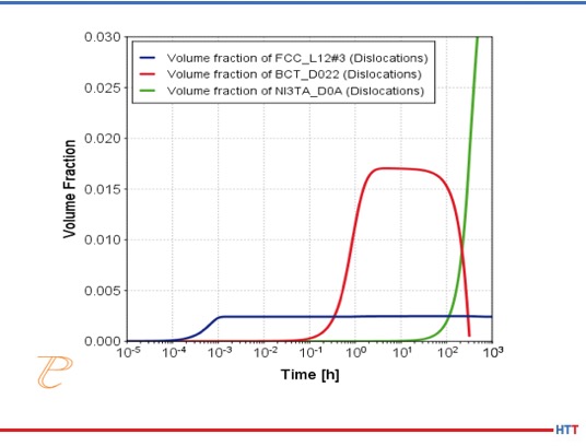
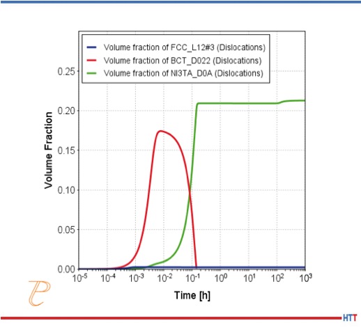
To understand this further, the authors first simulated the extent of this segregation using the Scheil-Gulliver model for solidification in Thermo-Calc[4] in conjunction with the diffusion module, DICTRA[4]. They then used the Precipitation module, TC-PRISMA to predict the precipitation kinetics of the deleterious delta phase for nominal feedstock compositions, as well as the compositions measured at dendrite boundaries. Both simulations, shown in Figures 1a and 1b, predict that a stable MC carbide forms, followed by some gamma double prime. Delta phase then forms at the expense of the gamma double prime. However the gamma double prime and delta phase both precipitate much more quickly in the segregated interdendritic region, due to the increased Nb and Mo. Delta phase is predicted to start forming around 1 hour, compared with 10 hours for the wrought material.

Figure 1. TC-PRISMA Precipitation simulations using nominal IN625 powder compositions (top) and segregated compositions (bottom) measured at the dendrite boundaries. Recalculated based on Reference 3.

While these calculations give insight to the reason why the conventional stress-relief heat treatment is not suitable, additional simulations can be made to identify a suitable temperature and time to both homogenize and stress-relieve the part, while avoiding deleterious phases. The authors of the study determined a post-build homogenization treatment was required to avoid deleterious delta phase precipitation.

Gas Carburizing Highly-Alloyed Steels

Highly-alloyed stainless steels can be gas carburized to increase the surface hardness, as well as improve the overall mechanical characteristics of the surface. However, an increase in chromium-rich carbides such as M23C6 or M7C3 can result in the decrease of chromium in the solid solution which leads to a reduction in corrosion resistance. Balancing these properties can be time consuming through trial and error experimentation, but CALPHAD-based tools can be used to identify suitable alloy compositions and heat treat windows, which are optimal for the application needs prior to testing in the laboratory.

Turpin et al. 5 made such a study, combining both experimental work and theoretical simulations to investigate carbon diffusion and phase transformations during gas carburization of high alloyed martensitic stainless steels. First, using thermodynamic calculations performed with Thermo-Calc 4 they determined the optimal balance between the carbide formation and chromium content of the alloy for corrosion resistance. They concluded:

  1. At 1750°F (955°C), which corresponds to the austenitization temperature of their alloy, M23C6 and then M7C3 will be the first carbides to precipitate in the austenite phase as the amount of carbon content in the alloy is increased.
  2. If the amount of carbon exceeds 3.8 wt% then M3C carbides are predicted to be stable. M3C carbides have a structure similar to cementite and preferentially precipitate at the grain boundaries which weaken the microstructure. Therefore, to avoid these phases, the overall content of carbon in the steel must be below this amount at the end of the carburizing process.
  3. Above 1.7 wt% C, the mole fraction (an indicator of the volume fraction) of M7C3 carbides exceeds 20%, and the chromium content of the alloy associated with these carbides is 65 wt%. Therefore, there is a correspondingly strong depletion of chromium from the matrix.
  4. To balance the desire for adding carbon into the matrix phase to obtain hardness with depleting the matrix of carbon, it was determined that the optimal amount of carbon in the matrix phase should not exceed 1 wt%. Thus, the thermodynamic calculations were used to establish a limit, without yet any consideration of the kinetics or time.

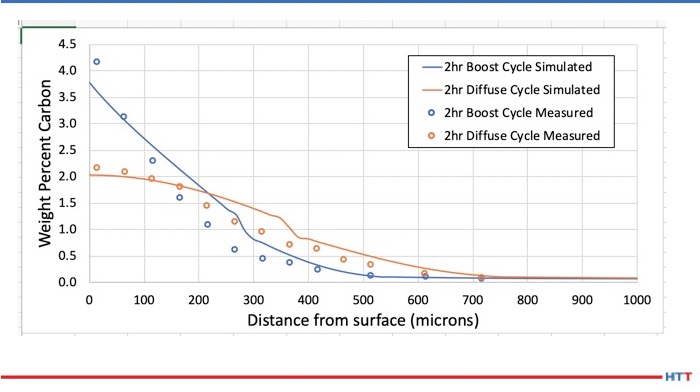
The second stage of the study then considered the diffusional reactions in the multi-component system during i) the carbon enrichment step and ii) the diffusion step of the gas carburizing process, and to determine how the composition and the amount of each phase vary with time and distance from the gas/solid interface and the carbon profile of the alloy as a function of time and distance. These calculations were made using the diffusion simulation software, DICTRA 4.

Consider the carbon enrichment step first. In DICTRA, several boundary conditions can be used for such a simulation, and in this work the carbon flux was determined experimentally using thermogravimetric measurements. During the diffusion step, the N2-CH4 mixture is replaced with pure N2, and the carbon flux at the surface of the samples is zero. To simulate this step using DICTRA, a zero carbon flux was applied as the boundary condition for two hours.

Figure 2 shows a simulated carbon profile for Fe-13Cr-5Co-3Ni-2Mo-0.07C, which is found to be in good agreement with the experimental values reported by Turpin et al. The authors concluded from this study that the carbon profile can be calculated and followed at any time if the boundary condition evolution at the gas-solid interface is known during the carburizing treatment.

Figure 2. DICTRA carbon diffusion profiles for Fe-13Cr-5Co-3Ni-2Mo-0.07C. Recalculated based on Reference 5.

Predicting β-transus Temperatures in Ti-Alloys

Many Titanium alloys respond well to heat treatments, through which the microstructure can be manipulated to optimize properties for a particular application. For example, some microstructures are better for high temperature creep, and some are better for fatigue strength. This is primarily achieved by controlling the nature and amount of α and β phases in the microstructure.

At high temperatures, titanium alloys are primarily β phase. At the β-transus temperature, the α phase becomes stable and can start to form. The β-transus temperature can change as a function of alloy chemistry. Knowing the β-transus temperature is critical to determining the nature and amount of α phase that will form during a heat treatment or thermal cycle.

Many alloying elements in Ti alloys have a strong effect on β-transus temperature. Knowing the actual β-transus for a specific chemistry is critical to determining suitable heat treating windows to obtain a specific set of material properties. However, even within a particular alloy specification, there can still be small compositional variations that have a significant effect on the β-transus. Thermo-Calc [4] can be used to calculate this if the exact chemistry is known, or to determine the potential distribution of β-transus temperatures for a given chemistry range.

Table 1 -- Composition specification for major elements in Ti-6-2-4-2 Alloy

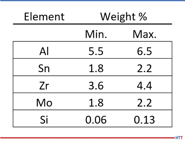
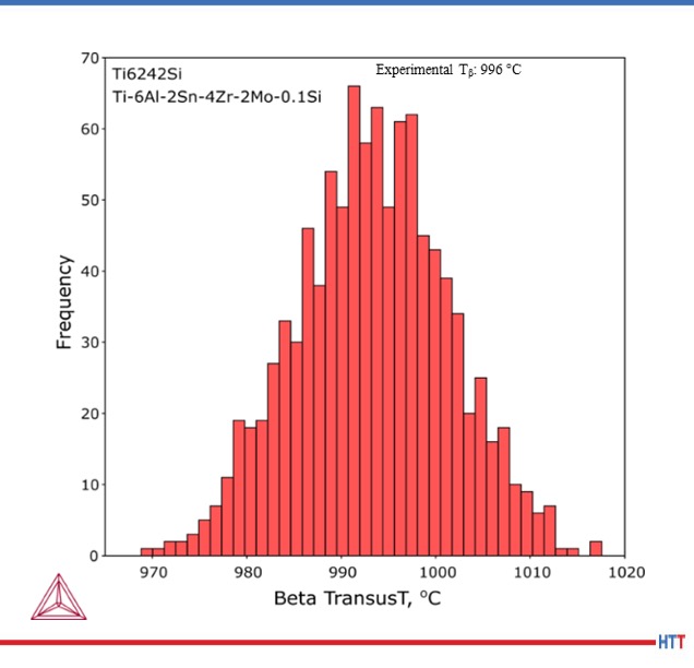
Table 1 shows the composition ranges for the major elements in Ti6-2-4-2Si (AMS 4919). Figure 3 shows the calculated distribution of β-transus temperatures in the composition specification of Ti6-2-4-2. Over 40 degrees variation is possible for compositions that lie within the specification and the calculations show good agreement with the experimentally measured values of 995°C ± 15°C (1823°F ± 27°F).[6]

Figure 3. Variation in Beta transus temperature for 1000 possible compositions within Ti-6-2-4-2 specification


Summary

In the 100th Column of the Heat Treat Doctor [7], Dan Herring, stated that heat treating can best be defined as “the controlled application of time, temperature and atmosphere to produce a predictable change in the internal structure (i.e. the microstructure) of a material.” However, variability arising from composition differences in materials can sometimes be challenging for heat treaters. The examples shown here have illustrated how modeling and simulation tools such as those based on the CALPHAD approach can be used to predict variability arising due to material composition. HTT

References

[1] National Research Council. 2008. “Integrated Computational Materials Engineering: A Transformational Discipline for Improved Competitiveness and National Security.” Washington, DC: The National Academies Press.

[2] Kaufman, L and Bernstein, H. Computer Calculation of Phase Diagram. New York: Academic Press Inc, 1970.

[3] Zhang, Fan, et al. “Effect of heat treatment on the microstructural evolution of a nickel-based superalloy additive-manufactured by laser powder bed fusion.” Acta Materialia 152 (2018) pp 200-214.

[4] Andersson, J O, et al. “Thermo-Calc and DICTRA, Computational tools for materials science.” Elsevier, CALPHAD, Vol. 26, (2002) pp. 273-312.

[5] Turpin, T, et al. “Carbon diffusion and phase transformations during gas carburizing of high-alloyed stainless steels: experimental study and theoretical modeling.” Met. Trans. A, Vol. 36A, (2005) pp 2751-2760.

[6] TIMET datasheet for TIMETAL® 6-2-4-2, TMC-0157 (2000).

[7] Herring, D “What is Heat Treating and Why Do We Do It?” Industrial Heating Magazine BNP Media (2011).


About the authors: Paul Mason is the president and Adam Hope, PhD is a materials scientist for Thermo-Calc Software, whose products assist academia, government, and industry to make calculations which predict or assist in the understanding of complex multicomponent alloys and non-metallic systems, as well as processes of industrial and scientific relevance.

For more information, contact Paul or Adam at info@thermocalc.com or (724) 731 0074


(Photo source: dayamay from pixabay.com)

Predicting the Effects of Composition Variation for Heat Treatment of Aerospace Alloys Read More »

Clifford-Jacobs Receives Improved Temperature Control System on Heat Treat Equipment

In today’s Heat Treat Today Technical Tuesday feature, learn more about how a temperature control system can improve the performance of heat treat equipment.

A century-old producer of die forgings recently needed to improve the process controls on its heat treating furnaces.

With process controls well over 10 years old, Clifford-Jacobs turned to Conrad Kacsik to improve its temperature process control system. The company, which serves a number of industries, including energy, aerospace, construction, mining, forestry, and rail, was eager to upgrade, particularly because the incumbent system was producing inconsistent work.

(source: Conard Kacsik)

The Challenge
Clifford-Jacobs was not getting consistent, repeatable results from its furnaces. The company also wanted more efficient and automated processes with data acquisition and electronic operating capability.

“We looked at a number of controls companies throughout the Midwest and interviewed them to learn about their experience with system controls and data acquisition,” said Bud Kinney, vice president of Innovation and Technology at IMT Corporation, the parent of Clifford-Jacobs. “We knew we wanted an integrated system so we started looking at companies that did that as a matter of course. Most companies are limited to traditional controls, but Conrad Kacsik has a lot of experience doing the exact type of job we needed.”

Increasing Demands
Clifford-Jacobs makes forged parts for a variety of clients. Although forging does not generally require as much precision as other types of processes, customers are increasingly demanding, said Kinney.

“We believe that sooner rather than later things like Nadcap will come into forging, and our customers are very interested in us being able to demonstrate that our processes are always in control, even forge heating,” Kinney said. “This project helps ensure that we meet those needs. We couldn’t track things like set-point input values before. That’s another element we wanted to manage.”

The System
Conrad Kacsik built a full process temperature control system that includes SCADA software from SpecView. They were able to retrofit the system on Clifford-Jacobs’ existing 16 furnaces, saving the company considerable expense and time. The temperature process control system uses Watlow F4T controllers paired with SpecView SCADA software, which allows for programming jobs/recipes, remote operation, secure (password protected) operation of furnaces, and accurate automatic temperature recording. Conrad Kacsik also added alert lights that allow the operators to quickly see the status of each furnace from the shop floor.

(source: Conrad Kacsik)

H2: Benefits of Temperature Control System Integration
Clifford-Jacobs has noted several beneficial results from the new temperature control system. These include:
• Increased accuracy. The new system runs each recipe exactly and records the results. The company can also control which employees can adjust temperature settings, preventing operators from rushing jobs with a higher temperature or inadvertently setting the furnace incorrectly.
• Higher efficiency. With preprogramming, each furnace is always at the exact temperature it needs to be for the given task. An automatic preheat setting also safely prepares the furnace for the workday—eliminating downtime or the need to send an employee in early to start the furnaces.
• More speed. Clifford-Jacobs can preprogram any recipe it needs, allowing for highly accurate and fast running of complex processes.
• More convenience. Clifford-Jacobs can operate their furnaces from anywhere with an internet connection, or via an iPad used by an approved employee.
• Precision for the future. The new system can be part of a Nadcap-approved process should the need arise. The SpecView software and advanced controllers automatically record each job and retain all data for verification.

The Results
“We used to have to use all kinds of resources to provide oversight on temperature control,” said Kinney. “This has given us a heating strategy. We write the recipes we want and just select from
those. In addition to that, we know exactly what every furnace is doing at all times.”

The company is also pleased with the increased efficiency. They only heat product when they are ready to run production, and the furnace only uses the exact energy needed for each recipe. They are also saving on staffing, as they used to have to schedule people to ensure the furnace was at the right temperature.

“With this system, we can develop recipes for each part we make, which is both convenient and precise. It’s doing exactly what we expected it to do,” said Kinney.

This article first appeared in December’s Heat Treat Today‘s Medical and Energy Heat Treating magazine.

(source: Conrad Kacsik)

Clifford-Jacobs Receives Improved Temperature Control System on Heat Treat Equipment Read More »

Future Heating of Industrial Furnaces

Climate change and fossil fuels are topics that can spur many lively conversations. In today’s Heat Treat Today Technical Tuesday feature, explore their connection as it relates to heating industrial furnaces in the future with Dr. Joachim G. Wüenning, president, WS Inc. and an expert in clean efficient combustion.

This article originally appeared in Heat Treat Today’s  March 2020 Aerospace print edition.


Joachim G. Wüenning, President of WS Inc.

Many people view climate change as the biggest threat to mankind. Technical and social efforts will be required to meet the goals, formulated in the “Paris Climate Agreement,” to limit global warming to less than 35.6° F (2° C).

Combustion of fossil fuels is by far the largest human contribution to global warming. Fossil fuel-fired power plants and internal combustion engines are already in the public focus. The transformation to alternative drives for vehicles has just started, and the days of coal-fired power plants are numbered.

Combustion of fossil fuels for industrial furnaces is also a large contributor to greenhouse gases and air pollution. The industrial heating sector is not in the public focus yet, but that will change soon; therefore the topic should be addressed proactively.

For mid- to long-term future industrial process heating, there are three main scenarios:

  • heating with renewable electricity, or
  • heating with non-fossil fuels, or
  • a combination of both.

Humans used non-fossil fuels for hundreds of thousands of years and are returning to that habit after a short period of about 250 years where fossil fuels were primarily used.

Reducing CO2 Now and In the Future

Heating a furnace using electricity is locally CO2 free, but an even greater amount of CO2 is emitted at power plants since the majority of electricity is generated by burning fossil fuels. For every kilowatt hour (kWh) produced, roughly one pound (~0.45kg) of CO2 is emitted into the atmosphere [1]. This is true for Germany, and the figures for the United States are in the same range.

Heating an industrial furnace with a typical temperature of around 1832°F (1000°C) with natural gas produces about 0.4kg CO2 for every kWh of available heat for a cold air burner, and less than 0.25kg/kWh CO2 when using a recuperative or regenerative burner where waste heat is recovered using a heat exchanger.

So, the short-term measure to reduce CO2 emissions is to use an efficient burner with heat recovery or to switch from electric to natural gas heating, which can cut CO2 emissions by 50% or more.

For a further reduction, we have to wait until electricity generation becomes predominantly regenerative, or we have to use green, non-fossil fuels. The possible paths to non-fossil heating of industrial furnaces are drafted in Figure 1. It shows that the short-term action should be improving the efficiency of burner systems or a switch from electric to gas heating. In the mid- to long-term future, there should be a healthy competition between non-fossil fuel gas and electricity, driving the prices for non-fossil energy down.

Figure 1

Changing Fuel Compositions

The most relevant characteristic for the interchangeability of fuel gases is the Wobbe Index (Figure 2), with the lower or upper heating value (Hi, Hs), the density of the fuel gas (r) and the density of dry air (r0). Fuel gases with the same temperature, pressure, and the same Wobbe Index will provide the same energy output from a burner. If the Wobbe Index is changing, the flow must be corrected by changing the fuel gas pressure or a flow throttle device to keep the burner power constant.

Figure 2

In most cases, the air does not need to be corrected since the ratio between stoichiometric air ratio and lower heating value is about 0.95 m3/kWh for common hydrocarbons. That means that a burner with a given heating power needs the same amount of air even when different fuel gases are used. A good rule of thumb is that one cubic meter per hour of air is required for every kilowatt of heating power.

If hydrogen is used as a fuel, about 15% less air is required. So, when hydrogen is added to natural gas and the fuel gas flow is corrected but the air flow is left unchanged, the system would be operated with somewhat more excess air, slightly less efficient but safe.

If gas fluctuations will occur in the future, adjusting the burners with more excess air would be an easy measure to ensure safe operation. With an effective heat recovery system and low exhaust gas temperatures, efficiency losses would be minimal.

Fuel Gases With High Hydrogen Content or Pure Hydrogen

The flame speed of hydrogen is much faster compared to hydrocarbons. That can cause some problems, especially in premixed burners where a flashback can occur. Another challenge resulting from faster combustion could be higher flame peak temperature leading to higher thermal NOx emissions. Modern low NOx methods are available to address this problem.

A positive effect of hydrogen can be a more reliable and easier ignition of burner systems. Many industrial burner systems can be operated with high percentages of hydrogen or with pure hydrogen with little or reasonable modifications.

Fuel Gases Containing Fuel Bound Nitrogen

Using ammonia or bio-gases with fuel bound nitrogen will produce excessive amounts of NOx-emissions when burned in most burner systems. There are a number of options to achieve low NOx-combustion with fuel bound nitrogen.

One method is fuel conditioning where fuel bound nitrogen is broken up into molecular nitrogen. This was successfully demonstrated using a stainless steel reactor in combination with a flameless oxidation burner system.[2] Another method would be exhaust gas cleaning by selective (SCR) or non-selective (SNCR) catalytic exhaust gas cleaning. Both processes require large investments and operating costs and should only be used if other options are not available.

The development of combustion systems with integrated treatment of fuel bound nitrogen would be the preferred method and will be an important topic for combustion research in the coming years. One approach is multi-stage flameless oxidation [3].

Fuel Conditioning

Fuel conditioning might be required to keep fuel gas properties within regulated limits inside the gas transport and distribution grid or for certain customers with special requirements. Fuel conditioning can be performed by blending different gases or by changing their compositions by using reformers or gas separation units like pressure swing adsorption (PSA) or membrane technology.

If future regulations propose a certain hydrogen content in the fuel gas grid, strategically placed steam reformers could keep the hydrogen content within certain ranges, even if there is no regenerative electricity available to operate electrolysers.

Reformers could also crack ammonia, ethanol, or methanol before being used as fuel gas to heat processes.

Outlook

There are several options towards non-electric, fossil-free industrial process heating. All these options have to be thoroughly investigated to keep a number of options open for future energy systems. The energy system of the future will be based on regenerative power generation but it will involve additional energy carriers to store and transport the energy. There are some challenges for combustion but there is no doubt that these can be overcome.

A fair and open competition between the different energy options will create the best solutions for society and the planet. A planned economy will not provide the fertile soil for innovations and entrepreneurship necessary to meet the challenges.

References

[1]    German Environment Agency, CO2 Grid Emission Factors from 1990 – 2018 for the German Energy Mix, March 2019

[2]    Domschke T., Becker C., Wüenning J.G., Thermal Use of Off‐Gases with High Ammonia Content – a Combination of Catalytic Cracking and Combustion, Chem. Eng. Technol., 21: 726-730

[3]   Wüenning J., Multistage Flameless Oxidation, AFRC Combustion Symposium, Waikoloa, HI, September 2019


About the Author: Joachim G. Wüenning is president of WS Wärmeprozesstechnik GmbH and his area of expertise is in clean efficient combustion, FLOX—flameless oxidation, heat recovery, radiant tubes, and recuperative, regenerative burners. This article originally appeared in Heat Treat Today’s  March 2020 Aerospace print edition.


(Image source: Seagull from pixabay.com)


Future Heating of Industrial Furnaces Read More »

Die Casting 101

Martin Reeves, Owner, Fontec-global, LLC

Die casting can be tricky to understand; additionally, the term has become something of a catch-all phrase for a production process that covers both low- and high-end technology. In this Original Heat Treat Today Technical Tuesday feature, come along with Martin Reeves, Owner of Fontec-Global, LLC, as he takes readers through the die casting process, giving helpful definitions of terms and easy-to-understand descriptions of processes.


The term "die cast" is one many will have heard referring to a particular part; sometimes as a recommendation, sometimes inferring a cheaper alternative, but always as a catch-all for a production process that encompasses a whole range of technologies from cheap and cheerful to the highest technology. So here is a quick overview of what can be termed as "die casting."

(source: fontec-global, LLC)

Die/permanent mold casting has become the dominant casting process for nonferrous alloys of aluminum, magnesium, and zinc, and with the growth of aluminum as a major structural component in automotive design, it is set to maintain that position in the future. This is an overview of the various ways and processes in which permanent metal molds are used today.

Typical metals used in die-casting are lower melting point alloys of aluminum, magnesium, and zinc. Lead and pewter are also cast in this way, and the original process was developed for creating movable type around 150 years ago for the fledgling printing industry. Copper and its alloys of brass and bronze can also be cast in this way, and even some cast irons have been cast in permanent molds with suitable mold coatings as the melting/casting temperatures approach that of the mold steels used.

Many of us will probably have used the process to make lead shot, fishing weights, or toy soldiers (showing my age now) in lead, which can be melted over a candle. Likewise, we see examples of die casting that can be produced in a vast range of sizes, and with high levels of surface finish and accuracy in our everyday life. It is this versatility to produce fine detail, accurate dimensions, and fine finishes that has driven the growth and development of the high pressure machines, which can produce these castings in high volumes (40 – more than 100/hr). This has ensured its continued popularity.

When we talk about die casting, it is normally the automated process using high pressure machines that force metal into a closed die; but there are several different processes that use permanent dies, and even within the high pressure die casting industry there are now different processes in use depending on the product, alloy, and industry. The majority of technological developments in the last 20 years have been in HPDC processes with bigger machines and computer controls.

Types of Die Casting Processes

The three principal (most popular) variations on the die casting process are:

  • High Pressure Die Casting (HPDC)
  • Low Pressure Die Casting (LPDC)
  • Gravity or Permanent Mold Die Casting

Hot Chamber Machine (source: fontec-global, LLC)

High Pressure Die Casting (HPDC) – This is now the most common form of nonferrous casting production, in which the molten metal is forced into the cavity under very high pressures. This process utilizes two different means of introducing the metal. A hot chamber machine will have the holding furnace installed as an integral part of the die casting machine, and the metal pump is immersed in the metal and forces metal directly into the cavity. Bigger and more sophisticated castings and alloys use a cold chamber process where the metal is held in a separate furnace and transferred into a shot sleeve on the machine linked to the die. It is then forced directly into the cavity by a ram.

Die Casting Machine (source: fontec-global, LLC)

All of these processes have variations that make them uniquely suited to specific types of castings or alloys. The development of novel processes and controls has expanded the scope of HPDC in recent years to the extent that safety critical structural castings can be produced and heat treated.

A historical problem with conventional die castings was the turbulence of the injection process, which caused air and gases to become trapped in the solid metal. Attempts to heat treat these castings resulted in expansion of the gases, which created blistering and eruptions on the surface and a reduction in mechanical properties. New processes, new alloys, and improved controls on die casting machines have now eliminated these issues, and thin-walled structural parts for vehicle bodies and structures are now normal production.

HPDC Ram Shot Control (source: fontec-global, LLC)

The development of bigger die casting machines and the evolution of shot control has expanded the scope and size of parts that can be produced. Shot control now means that instead of the ram simply moving at a steady speed to push the metal into the cavity, the movement profile can be controlled to move the metal gently at first to avoid air entrapment, and then intensifying towards the end of the stroke to ensure complete filling and improvements in metal density. When this feature is combined with vacuum assistance in the die, then the casting quality is improved dramatically, and along with newly developed alloys, can be heat treated to a T6 level for optimum properties.

Cold Chamber (source: fontec-global, LLC, UMLdiagram)

Cold Chamber Machines -- These allow for the metal to be dispensed into the shot sleeve (plunger cylinder) from an outside source. The transfer can be simply with a hand ladle, an automated ladle arm or robot, or via a pump or pressurized holding furnace to achieve an accurate and repeatable mass of metal.

Over the last 20 years or so, the size of die casting machines has increased dramatically to accommodate both heavier and larger castings. The capacity of a machine is defined as the locking force that can be applied to the die platens, and this has now reached over 5,000 tons of force. This allows for larger, thin-walled parts, such as complete door frames to be cast as a single piece.

Hot Chamber (source: fontec-global, LLC)

Hot Chamber Machines -- These, on the other hand, have the holding furnace as an integral part of the die casting machine, and metal is transferred via a pump that is permanently immersed in the metal. A plunger is adjusted to push a defined amount of metal into the die for each cycle.

Because of the limitations of the furnace and immersed pump, this process is confined to smaller die casting machines and parts. Because of aluminum’s aggressive affinity for ferrous metals, this process is more often used for zinc and magnesium casting.

Vertical High Pressure Machines -- These use a similar technology to conventional horizontal machines, but the shot sleeve is vertical and is filled completely in a vertical orientation before injection, allowing a less turbulent flow of metal into the die.

Vertical machines can also use a vacuum and siphon tube system to fill the shot sleeve where the metal is sucked from the holding furnace by a vacuum in the die cavity. Like the low pressure process, it has the advantage of creating a smooth metal flow into the die while the vacuum, strong enough to suck the metal, has the added advantage of a partial degassing effect and gives better quality castings.

There are variations of High Pressure Die Casting that generally have well defined niche markets:

Semi-solid casting, also known as Thixotropic or Rheocasting, uses a similar machine; but instead of molten metal, a billet of semi-solid metal is inserted into the shot sleeve before injection into the die.

The process uses a property of aluminum alloys to be solidified in a way that retains approximately 40-60% liquid, is stable enough to be handled, but can be cut with a knife. The advantage of this process is in creating a casting with similar properties to a forging that can be heat treated and polished. The downside has been the overall cost compared to conventional castings.

Metal powder injection uses fine metal powders with a binder material instead of molten metal, and is poured into the shot sleeve in measured amounts and then introduced into the die and compacted by the plunger. The part is then sintered to remove the binder and consolidate the part. This is used for small and intricate parts where very specific alloy mixes can be created without having to melt an alloy. The process is also used for some magnesium parts overcoming the dangers associated with processing molten magnesium.

Low Pressure Die Casting (LP casting) -- This is used almost exclusively for aluminum road wheels as well as other high integrity and safety critical parts where heat treatment is also a prerequisite to achieve mechanical properties; in this process, the molten metal is forced into the die cavity by pressure in the holding furnace below the die, which raises the molten metal into the die where it is held until the narrow inlet area solidifies and the pressure is released. The smooth flow characteristics provide a high quality casting that can be heat treated.

Gravity (Permanent Mold) Die Casting is maybe the simplest of the die casting processes and can vary from a simple mold for lead shot or fishing where the molten metal is poured directly into either static or tilting molds and flows by gravity into the cavity.

Static molds are filled directly by hand or auto ladle into a split metal die. After solidification, the die is opened and the casting, with runner system, are removed.

Tilting dies are mounted on a tilting mechanism, and the metal is poured into a tundish attached to the die. After filling, the die is tilted to allow the metal to run from the tundish into the die cavity. This enables large castings to be made as the tundish can be filled fully before tilting. Castings of 100 to 300 lbs. are not uncommon, and the limit is normally the size of the die block.

An advantage of this process is the ability to use sand cores to create hollow internal shapes in castings. In gravity and low pressure die casting, the metal flow is gentle enough that sand cores can be used without breaking up and producing hard inclusions in the casting. In HPDC, the speed and turbulence of the metal entering the die is violent enough to break conventional sand cores. There are some foundries using salt cores, which are much harder, and must be dissolved from the casting. They can also create corrosion problems if not done correctly.

Centrifugal casting is used primarily in the casting of pipes and tubes in a variety of ferrous and nonferrous alloys. Molten metal is poured into a spinning tubular mold where centrifugal forces force it into an even coating on the wall of the mold, which is then cooled to create the pipe. The process is predominantly for ductile iron water distribution piping as well as engineering pipe and tube stock.

There are two basic processes used industrially--horizontally spun molds and vertically spun molds.

The horizontal process is used for longer pipes--up to 6 m (20 ft) long--with molten metal being introduced simply at one end and allowed to flow or progress along the mold length (DeLavaud process) to provide a more accurate wall thickness in the finished pipe.

The vertical process is used for smaller cylindrical parts, such as brake drums and other parts where a more dense, defect free metal structure is required. The process is confined to simpler geometries where no or simple cores can be used. Brake drums and discs would be typical parts in grey cast iron.

Direct Chill Cast Billets (source: fontec-global, LLC)

Continuous casting is a process used to continuously cast various alloys into billets, Direct Chill Casting (DCC), for further processing such as for extrusion, or to provide a continuous supply of form to be cut off and processed. The molten metal is poured into a tundish, which provides a continuous and controlled flow of metal into a water-cooled die, which moves up and down as the metal solidifies and keeps the solid metal moving downwards, making more room for new metal being poured.

Slush casting is not such a common process and is used where a hollow part is required with simple geometry and a hollow shape without the use of cores. Molten metal is poured into a mold and given enough time for a solid skin to form before any excess metal is poured out of the mold. The result is a hollow casting. Used traditionally in the art world for hollow sculptures, decorative pieces, etc., it can be used with most alloys but more often with pewter and precious metals.

Counter pressure casting (CPC) uses two separate pressure chambers, creating pressure in the holding furnace above the metal surface while equalizing this with a vacuum above the furnace and in the mold cavity. The result is to draw the molten metal into the mold cavity with the minimum of disturbance and turbulence, thus ensuring a sound casting. The metal is encouraged to solidify with water or air cooling at the in-gate area before pressures are released.

Terminology – some common terms used in the foundry industry:

- Die or Mold: the main component of die casting. The terms can vary depending on location and industry.

- Clamping force: the force exerted between the two halves of the die (the platens), which resist the hydrostatic force from the metal entering the cavity at high pressure.

- Platen: the main carrying plate on the die casting machine to which one half of the die is attached.

- Ram: the piston or plunger that is used to force the metal into the die.

- Tundish: a simple bowl arrangement that allows for metal to be accumulated before or during a casting process.

- Cores: used to create internal cavities in castings. They can be re-useable mechanical components of the die, or more often in LP and gravity they will be expendable pieces made from a resin-bonded sand.

- Holding furnace: used to hold the metal at the chosen casting temperature during casting operations. This is refilled periodically to maintain consistent production.

- Shot sleeve: connected to one half of the die and allows metal to be introduced and held prior to being injected into the die.

- Gooseneck: named for its similarity to a goose's neck, this is the pump unit that sits in the metal and supplies metal in a hot chamber machine.


Die Casting Defects – some terms that refer to common defects on die castings:

- Mis-Runs: where the metal has failed to completely fill the die cavity.

- Porosity: internal voids created by gas trapment or evolution during the solidifying process.

- Blow holes: produced as a result of moisture or contamination on the die or core surface when metal is introduced and caused by the rapid expansion of moisture.

- Inclusions: foreign matter that has become trapped in the casting, such as core sand, oxide particles, etc.

- Hot tears: when the casting strength is insufficient to withstand cooling contraction during solidification.

- Cold shuts: created when the metal entering the die is too cold and solidifies prematurely in some positions while metal is still entering the die.

- Die soldering: aluminum has an aggressive appetite for iron, and certain alloys will attack the steel dies even in the short time for die casting injection, creating adhesion of the casting.

- Heat checking: a form of thermal fatigue cracking where temperature cycling at the die surface creates fine cracks that encourage sticking and degrade the surface finish of the casting.

- Shrinkage: found in castings with heavy sections with poor connections to the main feed path of metal. The contraction to the solid state can create shrinkage depressions at the surface or internal voids.

- Laminations: where cold dies allow rapid solidification of a thin skin before final solidification of the main mass.

Die Casting 101 Read More »

High-Temp Differential-Expansion Problem and How to Solve It


Source: Vac Aero International Inc.


If you’ve ever tried to braze together materials that have widely different Coefficients of Thermal Expansion (COE’s), you know that the material with the higher expansion rate will grow faster than the other when heated and contract faster when cooled down. You also know that once the two different materials have been brazed together and cooling begins, the shrinkage-rate differences between those two materials can produce significant shear stresses at the brazed interface between them and be so strong that the thin brazed joint may be torn apart at either interface. Other similar weaknesses and damage can result as well.

In this HTT Best of the Web Technical Tuesday feature, Dan Kay of Kay and Associates, a vacuum and atmosphere brazing consultant, explains the details of this problem and the solution.

Dan Kay
Brazing Engineer
Kay and Associates

An excerpt: “Today’s brazing technology is based on a strong foundation of the brazing experiences of many people around the world over a period of many decades (even centuries). I’ve now been very active in the brazing world for almost 50 years and, like my predecessors in the world of brazing, I’ve learned a lot about this fascinating joining process (and I’m still learning). In the article, I’d like to share with you one of my brazing experiences from many years back, one that involved high-temperature differential-expansion between an 18″ (45 cm) diameter tool steel die and a thin carbide plate (round disc) that needed to be brazed to the die’s front surface for wear-protection.”

In this article, Dan, who is also a HTT consultant, helps readers understand the high-temp differential-expansion problem, explore what steps can be taken to prevent it, and ties it all together so that readers can clearly understand what to do.

Read the entire article from Vac Aero International,  An Old High-Temp Differential-Expansion Problem

Image source: Vac Aero International Inc.

High-Temp Differential-Expansion Problem and How to Solve It Read More »

Can You HIP It? Investigating Hot Isostatic Pressing

Derek Denlinger
Corporate Lead Metallurgist
Paulo

What is HIP? Hint: It doesn’t mean you are fashionable or trendy! In this HTT original content Technical Tuesday feature, Derek Denlinger, corporate lead metallurgist for Paulo who has recently been focusing on heat treatment for additive manufacturing and hot isostatic pressing, shares how this process can improve mechanical characteristics of high-performance additive manufactured components.


Additive manufacturing has steadily asserted itself as a viable method for producing complex components in aerospace, medical, and other high-performance applications. And if you hang out in metallurgy circles (who wouldn’t want to?), you can’t hear “additive manufacturing” without also hearing about hot isostatic pressing, or HIP. That’s because the HIP process, which applies high heat and high pressure to densify parts, has shown promise in improving the mechanical characteristics of high-performance additive manufactured components.

But while that’s the most popular use case for HIP, it’s far from the only one.

HIP Applications

HIP is recently popular thanks to the prevalence of additive manufacturing for high-performance aerospace parts or medical devices like artificial hips, but the process is over 60 years old.

HIP was initially developed as a diffusion bonding technique. In diffusion bonding, high heat and pressure work together to weld similar or dissimilar metal surfaces without filler materials. However, metallurgists observed that those process characteristics also improved mechanical performance by eliminating casting porosity — the small bubbles of gas that can form during the solidification process of cast metals — and imparting a homogenous grain structure throughout the whole part. Porous parts or parts with variable grain structures are less durable and cannot stand up to the stress of severe service.

A similar phenomenon occurs during an additive manufacturing process called powder bed fusion. Powder bed fusion naturally leaves small voids within parts. Those small voids can cause big problems if they aren’t eliminated.

In addition to use alongside additive manufacturing and diffusion bonding of parts, HIP is typically specified as a densification process complementary to powder compaction and sintering as well as metal injection molding. It’s most often specified in aerospace, medical and dental, oil and gas, power generation, firearm, and jewelry manufacturing.

Materials Ideal for HIP

A wide array of materials can be HIP’ed in the high-pressure argon environment a unit creates. Such an atmosphere is ideal for:

  • Carbon steel
  • Tool steels
  • Duplex, martensitic, and austenitic stainless steels
  • Nickel-based alloys
  • Cobalt-based alloys
  • Titanium

The author, Derek Denlinger, in front of the HIP vessel

HIP Advantages

A common critique of HIP among some manufacturers is that it’s a costly, unnecessary, extra step in the manufacturing process. The word “overkill” comes to mind, and it’s true that some thermal processors aggressively market the process to manufacturers who make parts for which HIP may not be a metallurgical necessity. But when it’s appropriately specified, HIP gives manufacturers several compelling advantages both upstream and downstream in their production process.

Design & Manufacturing Freedom – Some parts feature highly complex shapes that are too complicated for traditional forging or casting. In response, manufacturers have either sacrificed performance with watered-down designs or added costly processing time by designing parts in pieces and then joining them via brazing. But the pressurized gas used in HIP finds its way into internal passages and blind features of complex parts, ensuring they achieve specified metallurgical characteristics while reducing the traditional failure risks.


Mechanical Characteristics – HIP has been shown to enhance key mechanical characteristics such as ductility, toughness, yield strength, and corrosion resistance. Fatigue, impact, wear, and abrasion resistance can also improve. Metallurgists have also observed that HIP’ed parts end up with less “data scatter.” Reducing data scatter enables design engineers to more accurately understand material performance and to know more precisely where the material’s limit exists. They can then design according to that known information.

Optimized Manufacturing – Whether parts are additive manufactured, cast, or forged, integration of HIP can streamline manufacturing. First, the combination of additive plus HIP’s densifying and solution treating capabilities mean more manufacturing stages can be accomplished in fewer steps. Second, manufacturers concerned about porosity can allow it to occur knowing that HIP can correct the issue.

Simultaneous Treatment – Older hot isostatic presses were typically designed with thicker walls which impeded quick cooling. That eliminated simultaneous treatment from the equation (and led some to believe the process was unsafe). Rapid quenching is built into many modern HIP models, allowing simultaneous heat treatment and hot isostatic pressing. The resulting time savings is significant. Improved performance of parts treated in this manner has also been observed.

Reducing Scrap – There’s always variability in manufacturing; the risk of scrapping some parts is ever-present. But HIP can help reduce scrap in two ways. First, it can be incorporated into regular production of parts with tricky designs to make up for potential upstream process deficiencies. Second, it can be applied as needed if a one-off problem occurs in a single batch. In either case, the potential savings are compelling.

Hot isostatic pressing is creating new possibilities for manufacturers of high-performance parts. For example, the Quintus Technologies QIH 122 unit was installed into Paulo’s Cleveland Division. The rapid cooling capability of the HIP vessel is comparable to vacuum furnace quenching. These properties make it possible to HIP and solution treat parts simultaneously, imparting decidedly better metallurgical properties while reducing turnaround time.

Paulo recently installed this Quintus Technologies QIH 122 rapid cooling hot isostatic press in its Cleveland, Ohio facility.

(All Images: Paulo)


Can You HIP It? Investigating Hot Isostatic Pressing Read More »

Bill Disler on Carburizing Trends in the Automotive Heat Treating World

Bill Disler President & CEO AFC-Holcroft

Automotive part designs and heat treating processes have undergone many changes over the years, especially the powertrain. By looking back at the progress of these changes, we can learn more about emerging trends in automotive heat treating today.

In this Heat Treat Today Technical Tuesday feature, Bill Disler, president and CEO of AFC-Holcroft, brings his familiarity with big atmosphere carburizing systems and LPC automotive cell carburizing systems and looks at how the evolution of equipment and process requests says a lot about the trends we see today in automotive heat treating.

This article originally appeared in Heat Treat Today’s June 2019 Automotive print edition.


Although many components undergo heat treatment processes, the powertrain—specifically, gears— typically requires more carburizing time than other automotive parts. Not surprisingly, the powertrain has also seen many changes in heat treatment trends.

Not only have powertrain designs gone through tremendous transformations but so has the equipment being used to process those evolved components. Having spent years on the supplier side of atmosphere furnaces, vacuum carburizing, and gas quench as well as induction systems, I find it interesting to look back at some of the drivers that have helped morph this industry’s heat treat needs.

Traditional Continuous Atmosphere Furnace

Large atmosphere pusher furnaces produced nearly all of the powertrain gears 20+ years ago. Today, cellular low-pressure carburizing (LPC) and gas quench systems carry the load, although the results have not been cost saving. Moving from high volume gas heated carburizing equipment to small batch carburizing in electrically heated furnaces did not reduce utility costs per part; instead, other areas adjusted to compensate. Eliminating the expense of hard grinding transmission gears was an acceptable rationale for this increase in both capital expense and operating costs. Eventually, streamlining the overall gear manufacturing process, combined with locating heat treat within machining lines, produced positive measurable results. Plant traffic decreased, minimizing safety risks. Cooler and cleaner furnace systems were designed. And installations were made easier. Many agreed the changes were justified.

Integrated Vacuum Heat Treat Cells

As we look back, many of these drivers for change proved valid. Others, not so much. In most cases, consumer preference for quiet powertrains necessitates hard grinding of gears. Green is in and talk of the absolute need for zero intergranular oxidation (IGO) in carburized gears has slowed. LPC/Gas post quenched parts are perceived as cleaner and leaner; however, it is often difficult to differentiate green parts from processed parts, so it has become a best practice to add part marking after carburizing and hardening to avoid even the remote risk of sending soft parts down the line to the next stage of manufacturing. Shot peening is still common for strength reasons. The ability to nest large cellular LPC systems within machining has been a success, but rarely are the installations as quick and easy as promised.

Hybrid Furnace Concepts

Conventional atmosphere furnace technology has advanced as well, although at a slower pace, in step with a renewed interest in energy efficiency, particularly in the U.S. where gas is cheap and electric is not. Combustion systems operate cleaner and at much higher efficiency than in the past. Having said that, it is curious how little interest end users have in trading cost-saving gas-heated systems for the easier to install, neater looking electric heating options. In addition, it is no longer common to use water for cooling conventional atmosphere furnace systems as end users do not want to deal with the cost and complications that accompany this option. The market is polarized over this. LPC systems rely on large water volumes for cooling, and they are small batch, electrically heated systems. At the same time, gas quench systems consume huge quantities of water and require giant 300 HP plus motors that are tough to manage in plant power systems.

Flexible and Re-deployable Heat Treat Systems

It is my observation that the automotive market is anticipating the next iteration of heat treat equipment. One type of process or equipment style will not fit all needs, yet all hope for the perfect single part flow solution—an elusive dream due to physics. The cost/time equation still does not balance, and carburizing offers the benefits many manufacturers are looking for, despite the desire to design the process out of practice. Many automotive transmission parts that were originally processed in LPC and gas quenched now use gas nitriding instead, even though gas nitriding is another long process, and nitriding introduces ammonia back into the process—something most automotive plants are not enthusiastic to have in their plants. Two steps forward and one step back.

Repackaging Continuous Furnace Systems

With the widening range of processes and solutions under exploration, as well as ever changing powertrain systems designed to accommodate supplemental electric motors, lighter weights, smaller cars, and larger SUVs, all we can be certain of is ongoing change. I believe that we have witnessed major adjustments in automotive heat treat processing as the pendulum has swung from big, multi-row atmosphere pushers with salt or oil quench to electric-heated cellular LPC and gas quench units. One surprising result has been the resurgence of salt quenching, which controls distortion of high-pressure gas at a much lower cost with less complexity. Salt, like gas, is a single-phase quench media: It does not boil in these processes like oil does, and it can be used at temperatures that support martensitic quench with far less thermal shock and much higher heat transfer than the options. Older processes carry the baggage of tarnished past reputations, but I no longer count them out. Today’s automation, process control technology, and innovation can provide the foundation for brand new concepts, repackaging of older ideas, and hybrids of multiple technologies. Together, these create building blocks that heat treat equipment suppliers will use to meet changing trends in automotive carburizing and heat treatment. It will be interesting to be involved in the journey as these changes take place.

About the Author: Bill Disler is president and CEO of AFC-Holcroft, part of the Aichelin Group located in Vienna, Austria. He is a member of the Board of Trustees -Metal Treating Institute (MTI), and a member of the Board of Advisors at Lawrence Technical University, College of Engineering in Southfield, Michigan. This article originally appeared in Heat Treat Today’s June 2019 Automotive print edition.

Bill Disler on Carburizing Trends in the Automotive Heat Treating World Read More »

Efficient Sample Preparation of Titanium Grade 2

Source: Buehler

Titanium is a crucial component in aerospace and defense applications as well as in the biomedical field. The high ratio of strength to density of titanium and its alloys mean that it is as strong as some steels, but with a fraction of the density. However, titanium is more difficult than steel to prepare as a metallographic sample due to its ductile nature that renders it easily susceptible to damage.

In this HTT Best of the Web Technical Tuesday feature, Buehler’s Tech Notes explores efficient preparation of titanium grade 2 samples.

An excerpt: “Titanium and its alloys’ high strength to density ratio and good corrosion resistance make them invaluable in aerospace, defense, and marine applications. Good biocompatibility also makes it quite useful in biomedical applications. It is as strong as some steels but a fraction of steel’s density. When preparing metallographic samples, one quickly learns, titanium is more difficult to prepare than steel as it ductile and readily damaged, but also has a relatively slow material removal or recovery rate, which poses a challenge to sample preparation.”

Buehler takes readers through the methods of sectioning, mounting, grinding and polishing, and etching when preparing grade 2 titanium for a sample.

Read More: Efficient Sample Preparation of Titanium Grade 2

Efficient Sample Preparation of Titanium Grade 2 Read More »

Inside the Carbon Nanotube Method for Airplane Production


Source: Design and Development Today


A modern airplane’s fuselage is composed of multiple sheets of different materials, not unlike a phyllo dough pastry. Once these layers are stacked and molded into the shape of a fuselage, they are transferred into warehouse-sized ovens and autoclaves, where the layers fuse together to form a resilient, aerodynamic shell.

MIT engineers have now developed a method to produce the same high level of composites without the enormous ovens. This discovery may speed up the manufacturing of airplanes and other large, high-performance composite structures.

In this HTT Best of the Web Technical Tuesday feature, Design and Development Today introduces us to carbon nanotubes, their usefulness in potentially taking airplane manufacturing to new heights, and what the future of the research surrounding this discovery looks like.

Brian Wardle, professor of aeronautics and astronautics at MIT

An excerpt: “‘If you’re making a primary structure like a fuselage or wing, you need to build a pressure vessel, or autoclave, the size of a two- or three-story building, which itself requires time and money to pressurize,’ says Brian Wardle, professor of aeronautics and astronautics at MIT. ‘These things are massive pieces of infrastructure. Now we can make primary structure materials without autoclave pressure, so we can get rid of all that infrastructure.'”

Read More: www.designdevelopmenttoday.com/industries/aerospace/news/21110057/a-new-approach-to-making-airplane-parts?lt.usr=70118934

Photo Credit: Melanie Gonick, MIT

Inside the Carbon Nanotube Method for Airplane Production Read More »

Refractory Anchor Design: 3 Important Things You Need to Know

Dan Szynal,
VP of Engineering and Technical Service,
the Plibrico Company

A significant number of refractory lining failures can be traced to either faulty design or improper installation of the anchor system. The tips of anchors in particular need special consideration due to their exposure to the highest temperatures.

In this Technical Tuesday feature for Heat Treat Today, Dan Szynal, Vice President of Engineering and Technical Service for the Plibrico Company, a manufacturer of monolithic refractories, gives 3 important tips for refractory engineers and managers to use in achieving an improved anchor design.


It is estimated that up to 40% of refractory lining failures can be attributed to a problem with the design of the anchor system or improper installation. This is a significant number. When designing a refractory lining for an industrial application, anchor design becomes one of the most important factors in creating an improved lining that is supported properly. In particular, the tips of the anchors experience the highest temperatures because they are closest to the hot face and thus become an important consideration.

Anchors have several functions. They hold the refractory to the wall to keep it from falling in. They also prevent wall buckling due to the internal thermal stresses created by high temperatures. And, to a lesser degree, anchors can also help support the load of the refractory weight.

To create a monolithic refractory lining that is properly supported and maximizes service life, here are three important metallic anchor tips you need to know.

Anchor Types and Service Temperatures

Figure 1.0: Recommended anchor tip temperature limits for various common alloys

For refractory linings using metallic anchor systems, refractory engineers and designers almost always use Class III austenitic stainless-steel anchors of various qualities. The typical grades of stainless steel used are AISI 304, 309, and 310. These contain chromium and nickel to provide the best corrosion resistance and ductility at high temperatures. For some applications in which temperatures are more extreme and the use of ceramic tile anchors is not practical for various reasons, AISI 330 and even Inconel 601 is sometimes used. These anchors have higher nickel content for superior oxidation resistance and tensile strength at temperatures of 2000°F or higher. Inconel 601 gives the added advantage of good resistance to both carburization and sulfidation in extreme applications.


Industry Best Anchor Practices

Anchor sizing for a refractory lining depends on the refractory thickness and number of components. Some designers use the practice of sizing the anchor height to be 75-85% through the main dense castable or gunned lining. Other rules of thumb used in the industry dictate that the anchor tip should be no more than two inches from the hot face of the refractory for thicker lining designs greater than 6-7″.

For refractory applications, it is useful to know the temperature gradient through the refractory lining–from the hot face to the cold face–to choose the proper anchor size so that one doesn’t exceed the temperature limit of the alloy being used. To help calculate the correct temperatures at different points in the refractory lining, many industry professionals will use a heat loss calculator/estimator. By using a heat loss calculator/estimator, one can choose the proper anchor height by determining the anchor tip temperature it will experience. There are numerous heat loss applications that can estimate the cold face of a furnace lining given the input conditions of a thermal unit. As part of its value-added service as a refractory solutions provider, Plibrico Company, LLC, has a web-based heat loss application that gives a good estimation of the thermal gradient of the refractory lining from hot face to cold face to maximize anchor thermal performance.

Figure 2.0: Typical refractory anchor lining configuration

For example, look at figure 2.0. You can see a 9″ side wall of refractory lining using 6″ of a typical 60% alumina low-cement castable and 3″ of 2300°F lightweight insulating castable for an application operating at 2000°F with an ambient temperature of 80°F. For this application, we would select 309 SS or 310 SS metallic anchors because the intermediate temperature at about 80% of the main lining thickness is at about 1900°F. Although 304 SS anchors would be more cost effective and are most commonly used in the industry, the anchor tips would oxidize at this temperature and would essentially burn out.


A Word on Anchor Tips

Standard practice for several years now has been to allow for expansion of the anchor tines by covering the anchor tips with plastic caps, dipping them in a wax, or putting tape on them. Metallic anchors expand at about three times the rate of alumino-silicate refractories. The expansion material affixed to the anchor tips burns out at low temperature and allows the anchor space to expand without causing cracks in the refractory.

Best practices in metallic anchor design also must include anchor spacing. Greatly a function of the specific equipment and geometry size, refractory engineers must consider the specific installation area. For example, anchor spacing patterns will be different in a flat wall or roof as compared to a section that has a transition of geometry or a less critical area of a vessel.

Anchor spacing should be based on the features of each specific project, such as mechanical properties of the anchor, and the refractory lining as a function of the temperature. Refractory engineers will use these properties in mathematical models to help create the optimal anchor spacing pattern and plan.

Often, failures commonly attributed to the refractory component can, in fact, be caused by deficiencies in the anchoring system. A strong anchoring system is key to maintaining monolithic refractory lining integrity, even when it is cracked, to prevent a total structural collapse.

To prevent vessel lining failures, increase service life, and maximize refractory performance, incorporate these metallic anchor tips. With these tips, it is possible to design and optimize an anchoring system that will work well with the demanding needs of refractory linings today.

For more information about metallic anchors and refractory anchoring systems, contact the Plibrico Company at contact@plibrico.com


Refractory Anchor Design: 3 Important Things You Need to Know Read More »