Nadcap accreditation is looked on by most of the heat treating world as a significant achievement and a guarantee of quality. It not only permits a company to perform heat treating for the Aerospace/Defense industries but also tells customers that this company has a high standard of quality.
So what is it, and how does it work?
In this HTT Best of the Web Technical Tuesday feature, Vac Aero International takes readers through the entire Nadcap accreditation process from start to finish, examining what it is, how it works, and troubleshooting problem areas.
An excerpt: “Nadcap accreditation benefits not only the company being audited but helps ensure their customers receive products and services that meet or exceed both their expectations and requirements. The audit and accreditation processes result in continuous improvement in multiple areas, with deficiencies (i.e., nonconformances) identified and corrected based on specific rules (i.e., guidelines) to ensure each process meets or exceeds industry standards.”
Vac Aero gives a detailed look at the common pitfalls in the accreditation process, useful resources and training courses to help companies prepare for their audit, and what to do after the audit is complete.
This article continues the ongoing discussion on Equipment Selection for Induction Hardening by Dr. Valery Rudnev, FASM, IFHTSE Fellow. Six previous installments in Dr. Rudnev’s series on equipment selection addressed selected aspects of scan hardening and continuous/progressive hardening systems. This post is the third in a discussion on equipment selection for one of four popular induction hardening techniques focusing on single-shot hardening systems.
Previous articles in the series on equipment selection for single-shot hardening are here (part 1) and here (part 2). To see the earlier articles in the Induction Hardening series at Heat TreatToday as well as other news about Dr. Rudnev, click here.
Single-Shot Inductors for Non-Cylinder Parts
Single-shot inductors can be successfully used for hardening not only components of classical cylinder geometries but other geometries as well. This includes workpieces of general conical shapes, such as elliptic, parabolic, hyperbolic geometries—and the list can grow. As an example, Figure 1 shows induction surface-hardened ball joints (ball studs) and the single-shot inductors used to harden them. Ball studs are used in automotive, off-road, and agricultural machinery and can be different in shape and size (Compare images on the left in Figure 1 with images on the right.), requiring noticeably different hardness patterns.
Figure 1. Surface-hardened ball joints (ball studs) and single-shot inductors used for its hardening. (Courtesy of Inductoheat Inc., an Inductotherm Group company.)
In any attempt to scan harden workpieces with appreciable diameter changes, the scan coil must have a sufficient gap to clear the largest diameter. When scanning the section(s) of the workpiece with smaller diameters, an inductor-to-shaft air gap might be very large, resulting in low electrical efficiency and potentially exhibiting difficulties in load matching as well as in controlling the austenitizing pattern along the length of the part producing "cold" and "hot" spots. Additional difficulties may appear in controlling the hardness pattern in regions (e.g., near geometrical irregularities) where good control is most needed.
Thus, the substantially different workpiece-to-inductor electromagnetic coupling variations might not permit using classical multiturn solenoid coils or scan inductors. In contrast, single-shot inductors allow not only better electromagnetic coupling along the entire length of heat treated components (Figure 2) but also better address the geometrical irregularities of heat treated workpieces, producing the required hardness patterns at minimum process times with superior metallurgical quality.
Figure 2. Single-shot inductors allow better electromagnetic coupling along the length of heat treated components properly addressing the geometrical complexity of the workpiece. (Courtesy of Inductoheat Inc., an Inductotherm Group company.)
As stated in Part 1 of this series, in contrast to scan hardening, a single-shot inductor can be contoured along the length of the part properly addressing the geometrical complexity of the workpiece. Furthermore, the use of flux concentrators helps drive the current into the desired areas and allows producing a well-defined hardness profile with minimum distortion. The trade-off here is that more finesse is required in the design stage to produce the properly profiled single-shot inductor at the lowest possible cost.¹ Errors are costly since these inductors are each custom made for a given part or application and modifications can be quite costly. Thus, computer modeling is a helpful assistant as an attempt to keep the development cost down and shorten the "learning curve".
Proper hardening of such components as output shafts, flanged shafts, planet carriers, yoke shafts, sun shafts, intermediate shafts, driveshafts, turbine shafts, and some others may require extensive copper profiling, making a single-shot hardening inductor a complex electromagnetic device.
Certain geometrical features such as flanges, diameter changes, bearing shoulders, grooves, undercuts, splines, etc., may distort the magnetic field generated by an inductor, which, in turn, can cause temperature deviations, making it challenging to achieve certain hardness patterns.
For components containing fillets, it is often necessary to increase the heat intensity in the fillet region owing to the geometrical specifics. Also, the larger mass of metal in the proximity of the heated fillet and behind the region to be hardened produces a substantial thermal “cold sink” effect.¹ This draws heat from the fillet due to thermal conduction, which must be compensated for by generating additional heating energy in the fillet area.
Needed energy surplus can be achieved by narrowing the current-carrying face of the crossover segment of the single-shot inductor (Figure 3). Here is a simplified illustration of an impact of a copper profiling of the inductor’s heating face: if the current-carrying portion of the inductor heating face is reduced by 50 percent, there is a corresponding increase in current density. This will be accompanied by an increase of the eddy current density induced within the respective region. According to the Joule effect, doubling the induced eddy current density increases the induced power density roughly by a factor of four. Also, attaching a magnetic flux concentrator to certain areas of the hardening inductor further enhances the localized heat intensity.
Figure 3. Longitudinal leg sections of single-shot indicators and their crossover segments can be profiled by relieving selected regions of the copper to accommodate workpiece geometrical features. Attaching a magnetic flux concentrator to certain areas of the inductor further enhances localized heat intensity. (From V. Rudnev, A. Goodwin, S. Fillip, W. West, J. Schwab, S. St. Pierre, Keys to long-lasting hardening inductors: Experience, materials, and precision, Adv. Mater. Processes, October 2015, pp. 48–52.)
When using a single-shot inductor, it is particularly important that the workpiece is properly located in the heating position because seemingly minor dislocations may noticeably affect the heat treat pattern and metallurgical quality of hardened parts.
Traditionally designed single-shot inductors may exhibit high process sensitivity that is associated with the electromagnetic proximity effect.¹ A change in positioning of the workpiece inside the single-shot inductor attributed to excessive bearing wear of the centers, improper machining of the centers and fixtures, incorrect part loading, and other factors may produce a correspondent appreciable variation in the hardness pattern (particularly within the fillet region, undercut areas, and the part’s end zone). A reduced hardness case depth and the formation of unwanted microstructural products associated with incomplete phase transformation may be the result of that. Magnitude and distribution of transient and residual stresses might also be altered. Thus, attention should be paid to part’s reliable positioning during heating and quenching cycles.
As can be concluded, there are good reasons for using single-shot hardening, scan hardening, or continuous/progressing hardening approaches in induction hardening applications. The decision must be well thought out based on many factors such as geometry specifics, product quality, production rate, design proficiency, limitations of available equipment, reliability requirements, cost considerations, and some other factors.
The next installment of this series, “Dr. Valery Rudnev on . . . ”, will continue the discussion on design features of induction single-shot hardening systems.
Extensive wear or fatigue from friction and contact stress cause many engineering components made of ferrous or titanium alloys to fail. In this Best of the Web
Edward Rolinski,”Dr Glow”, Advanced Heat Treat
Technical Tuesday feature, Edward Rolinski, aka Dr. Glow, from Advanced Heat Treat Corp., compares “wear resistance between engineering components that were carburized vs nitrided,” originally published in his article, “Tribological Performance-Enhancing Surface Treatments for Improving Durability of Engineering Components” at AHT’s website.
An excerpt:
“The results of the tribological studies strongly suggest that for many engineering components, the application of nitriding may be more beneficial than carburizing since the nitrided layer had better wear properties than the carburized layer despite the fact that the layer was about four times as thick.”
Rolinski defines the uses, advantages, and tribological behavior of nitrided and carburized steel and provides illustrations of samples subjected to both treatments.
Main image photo credit/caption: Advanced Heat Treat Corp / Advanced Heat Treat’s Cullman, Alabama, location ion nitroding vessel, which the company says is one of the largest in the United States—”big enough for two small cars to fit inside.”
Heat TreatToday’s regular contributor Jason Schulze of Conrad Kacsik (“Jason Schulze on AMS2750E” series) interviewed Shaun Kim from Byington Heat Treating, located in Santa Clara, California, about the company’s experience preparing for and working through the Nadcap accreditation process. Shaun is the quality director at Byington Heat Treating.
The Byington Steel Treating Inc team
As a quality director at a commercial heat treat facility, I’ve been presented with some challenging situations. I take each challenge and examine it in any way I can, or at least, in any way that I know how. I like to think I’m a detail-oriented, evidence-based thinker with the ability to, at the very least, recognize gaps even if I’m not sure how to fill them. In short, the challenges drive me to learn more, and in the end, that is what I’m after. That is what I got out of the Nadcap process: a learning experience that has since prepared me for the next round.
My name is Shaun Kim. I’m the Director of Quality at Byington Steel Treating located in the California Bay Area. In fact, we are now the only Nadcap-approved commercial heat treat facility in the area. Byington Steel Treating has been around since 1952, heat-treating materials from carbon steels to aluminum allows to superalloys. Our capabilities have grown through the years and include hardness and conductivity testing. As we heat treat to AMS2759 (and family), AMS2770, and AMS2771, as well as material specifications, Nadcap accreditation was inevitable.
Sean Byington, CEO, Byington Heat Treating
The vision of Nadcap accreditation in heat treat was initiated and fully supported by our CEO Sean Byington. I know that, for many in the field, management may not supply the full resources needed to achieve Nadcap approval, but for me, that was not the case. Our CEO offered all the necessary resources to achieve accreditation. My challenge, once I first gained access to the eAudit.net website, was the new requirements within the checklist. As I stated, I’m detail-oriented, so I examined the checklists closely and, in the process, realized that in order to achieve Nadcap accreditation, simply conforming to an AMS specification wouldn’t be enough.
My biggest challenge was pyrometry. At the time I didn’t understand AMS2750E very well, so I intently read the specification until it started to make sense. I must have read that specification 10-plus times. Our initial Nadcap audit did not go well. It wasn’t that we were not doing what was required; it was that we did not have those requirements documented. We ended up going through the risk-mitigation process, otherwise, we would have had to wait two years to re-apply for Nadcap heat treat accreditation—something our team and CEO was not willing to do. If I had to point out some things I would have done differently pre-risk mitigation, I would have a) given myself more time to prepare, b) hired an industry expert to perform a gap-analysis using the AC7102 checklists, and c) hired an industry expert to facilitate the audit.
Slide from the Nadcap training Jason Schulze provides on behalf of Conrad Kacsik
Back to the risk mitigation process. The Nadcap risk mitigation process essentially consists of addressing all findings received from the eAudit.net system. PRI Staff Engineers will review root cause and corrective actions as they normally would during a reaccreditation audit. Prior to the risk mitigation process, we engaged an industry expert to help us review the findings to ensure that what we were capturing would improve our process and get the findings closed. Even though the risk mitigation process, we learned a lot about the response expectations and just how far we had to dive into our process to find the root cause and take corrective action. In the end, I must admit, I wouldn’t have changed anything. Going through the pains of risk mitigation prepared our company for the stringent requirements that come when processing aerospace parts to the requirements of Nadcap. Nadcap is a serious thing, and we wanted to learn as much as we could even if it meant putting a lot of time and effort into risk mitigation, which we did.
Internal audits gas analysis results can provide a learning opportunity.
Post-risk-mitigation, my experience was completely different and so was our approach. We retained our consultant who walked us through a gap analysis and supplied us with a close-out letter, laying out each gap for each checklist and how to close the gap. Once we had this information, and with an open line of communication to our consultant, we modified our procedures/forms and re-trained our staff in line with changes and requirements. At that point, my understanding of the Nadcap requirements, as well as AMS2750E, had improved greatly, which helped us through the process.
The time came for us to have our initial Nadcap heat treat audit. This process was tough. We had worked hard to close all the gaps we could think of. The auditor did not necessarily contribute to the tough process; it was more about the under-the-gun feeling. We had worked hard and invested the time and money to ensure a successful audit, and we were eager to experience the reward. Of course, there were several times we did not see eye-to-eye with the auditor, but in the end, we had a very successful audit. We passed with room to spare.
Interior of a vacuum furnace
In the end, I learned a lot through the process of Nadcap accreditation in heat treat. I’m a strong believer that you will never learn anything unless you make mistakes along the way and identify why it happened. There is no way for us to learn unless someone points it out or an event forces us to recognize the gap and we then address it.
Almost immediately, we began receiving RFQs which required Nadcap accreditation in heat treat. We have been processing quite a bit of work which requires Nadcap approval and aim to get more. If I could share any advice it would be the following:
Start from the beginning. Get the checklist and fill it out honestly—be honest with yourself about your capabilities.
It will not help you to ignore the gaps. Identify the gaps and start with those areas for improvement.
I recommend getting a consultant familiar with the Nadcap process of audits. The more you learn, the better off you will be.
If you would like to contact me for questions regarding my experience in our Nadcap heat treat accreditation process, please feel free to email me at skim@byingtonsteel.com. I look forward to sharing my experience and learning from yours.
Jason Schulze of Conrad Kacsik, regular contributor to Heat Treat Today (“Jason Schulze on AMS2750E” series)
Written by Jason Schulze from questions presented by Jason Schulze using responses submitted by Shaun Kim from Byington Heat Treating.
Ron Beltz, Bluestreak | Bright AM’s™ Director of Strategic Accounts
Additive Manufacturing (AM) is a disruptive technology trend that is continuing to influence the future of the manufacturing industry and will continue to provide additional opportunities for heat treaters going forward. The global market for 3D printing and directly related services is continuing to have significant growth each year. The 2019 Wohlers Report (which draws upon the expertise of 80 authors and contributors located in 32 countries) forecasts for 2020 $15.8 billion for all AM products and services worldwide and expects that revenue forecast to climb to $23.9 billion in 2022, and $35.6 billion in 2024. In this article, Ron Beltz, Bluestreak | Bright AM’s™ Director of Strategic Accounts, discusses heat treating, additive manufacturing, and serialization.
Additive manufacturing has been advancing rapidly over the last few years and has been used by a wide variety of companies to quickly produce working prototypes and parts. Now that the prototypes have been fine-tuned, tested, and proven in real-world situations, more and more parts are being mass-produced via additive manufacturing. In years past, plastic has been used as the primary 3D printing material, but now, other materials and combinations of materials continue to be incorporated into additively manufactured products, such as various metals, cements, wood, and even glass.
Using micrometer-thick digital “slices” generated from computer-aided design to 3D-print a solid object with metal powders is definitely not the end of the story. Just as with casting or machining metal parts, a series of post-processing heat treatments are required to reduce the part’s internal stresses, increase its density, and even help develop the final shape, finish, and necessary physical properties.
The relationship between heat treatment and 3D printing has been proven not only to be beneficial but is now a definite part-specification requirement in many cases, as the heat treatment of 3D printed projects has been shown to dramatically increase the strength and stiffness of certain parts. Also, by combining heat treatment processes with 3D printing, manufacturers are able to directly thermocouple the pieces they are producing while also improving the specific characteristics of the end product (i.e., hardness, elongation, fatigue strength, etc.).
Some type of heat treatment is absolutely necessary for most AM parts. One of the issues of additive manufacturing is the possibility of internal defects. Direct metal laser sintering (DMLS) regularly produces near 100% dense parts, but to provide another level of control to help reduce part failure, hot isostatic pressing (HIP), instead of heat treating, is successfully being used by many aerospace companies and in the casting industry. As a post-additive manufacturing treatment, HIP is also used to remove internal defects and increase the overall strength of the part to help reduce fatigue failure.
The HIP process works by applying high heat and uniform pressure to fully solidify the part. NADCAP certification is a common requirement for HIP processing as these parts are typically used in aerospace applications. Many 3D-printed components that are expected to be used in nuclear, gas turbine, marine, or medical applications also require an additional HIP treatment to fully densify the metal part, eliminating pores that can lead to catastrophic failures.
Solution annealing is another heat treatment option for production-grade parts (typically aluminum) that require enhanced mechanical properties. The process heats the part to a high temperature, and then it is rapidly cooled, resulting in a change in microstructure and improved ductility. Additionally, vacuum heat treatments are frequently used for metal parts produced via additive manufacturing.
To gain an additional share of the AM market, some heat treaters are adding other in-house post-AM part processing services, such as:
Machining: Machining of surfaces, support structures, threads, etc., likely will be required to ensure dimensional accuracy of the finished part. Few AM parts meet specifications “as built,” and if nothing else, the surface of the part that was connected to the build plate will need to be finished. Most manufacturing companies already have machining systems on hand, but heat treaters should poll their customers to see if this (or the other services mentioned below) is something they need.
Surface Treatments: Surface finishing of specific parts also might be required to improve the overall quality of the surface finish¹, reduce surface roughness, clean internal channels, or remove partially melted particles on a part.
Inspection and Testing: Metrology, inspection, and nondestructive testing of parts will also be needed post-processing and possibly at multiple points during manufacturing production and post-processing. Destructive testing of a sampling of parts in a production run and analysis of test/witness coupons or tensile bars, powder chemistry, material microstructure, and more may also be needed to gather the necessary data to help with process qualification and ultimately part certification.
There are some opportunities for heat treaters to provide additional services to their existing and future customer base while increasing their value as a long-term business partner.
Regarding actual additive manufacturing part production issues, there are two related MES/QMS software products currently on the market: Bluestreak and Bright AM. Both products were developed over the past fourteen years by Throughput Consulting Inc., headquartered in Delafield, Wisconsin. The flagship Bluestreak MES/QMS software platform is being used by heat treaters and other post-processing service-based manufacturing companies such as fabrication, powder coating, surface finishing, plating, and forge. However, the Bright AM MES/QMS software system is being used by additive manufacturing production facilities, which have some unique requirements (identified in the paragraphs below). Manufacturers and OEMs may already be using a production control, work order management and quality management system designed by Throughput Consulting Inc. which allows for excellent integration between systems and makes interactive business much easier, less error-prone, and more highly automated while eliminating much of the paper documents/forms that change hands between companies today.
When additively manufacturing parts in an AM production facility, especially in mass production of repeat part builds, regardless of whether it is a captive or commercial 3D-printing facility, some challenges have surfaced that were not as much an issue with the previous Industry 3.0 subtractive manufacturing production methodologies.
As you will see in the following paragraphs, some of these challenges carry over into heat treating and testing of these parts.
Printing a myriad of parts, each with its own serial number, that have been combined or batched into the same build plate/platform (see Figure 1 below) raises the additional challenge of guaranteeing that unique serial numbers were generated for each part, then 3D-printed on each Part, and subsequently tracked by each individual serial number.
Figure 1 Multiple parts on the same build plate (courtesy of Materialise)
Similar to tracking parts through the various operating steps that comprise your various heat treat processes, AM facilities also must have real-time visibility into each step of the part-production process, tracking where each part is in the overall process (i.e., which operating step each part is on, all while integrating the necessary quality management into the mix.
When AM production facilities send many different kinds of parts (all with unique serial numbers) to heat treat facilities with some parts requiring different processing steps, the software systems need to be able to track in real-time exactly where each individual part is located within the facility. Even though the heat treater is not responsible for generating and assigning serial numbers to the parts, there still needs to be complete traceability, accountability, and auditability of every step of processing that was associated with that part, especially if it was determined that there was a part failure in the aerospace, aviation, or medical end-use application of that particular part.
Serial numbers on parts can be generated from multiple user-defined serial number formats or templates, along with the ability to specify certain characters that should be excluded from automatically generated serial numbers (such as “o”, “l”, “I”, “x”). Each company, division, or AM production facility may have a different format it wants to use, such as a combination of plant #, date, time, and printer #. Regardless of the format used, serial numbers must be unique. Additionally, the template used must be able to be individually assignable for every customer part (and the same part # might be used by multiple customers).
There are multiple ways that serial numbers can be applied to the parts before they are sent for heat treating. Both AM facilities’ and heat treaters’ production floor software must provide for detailed serial number tracking of all parts throughout the build and post processing activities, from the beginning of AM production (after the part design phase) all the way through to heat treating, finishing, testing, and shipping.
Sometimes AM parts that heat treaters receive will also have a build plate ID as an additional identifier, along with the serial number. Build plate IDs are typically platform-centric, with the appropriate process management/operating steps applied for the various parts that are to be produced on that platform or build plate. The build ID needs to connect all of the related work orders for traceability as well as electronically linking all documentation/forms associated with a particular work order and build ID. The documentation audit trail of individual processing activities needs to be kept intact when the parts are sent to an outside heat treat vendor as another one of the required operating steps for that part. In addition to this, the actual build plate can either be tracked as a separate piece of equipment (typical) or as an inventory item.
For heat treating as well as AM production facilities, an integrated equipment maintenance module needs to be tied directly to production control (on the selected piece of equipment) and part specification requirements, to ensure the build plate, 3D printers, furnaces, testing equipment, etc., are serviced, calibrated, and/or maintained appropriately for compliance and optimal use.
Along with having a work order just for the build plate, there can also potentially be one work order for each part on the build plate, and that work order can be used to generate a vendor traveler to accompany the parts to the offsite heat-treating facility. Figure 2 below gives an example of two different part-build work orders on the same build plate.
The build work order tracks the actual build process, similar to tracking every step of the heat treat process, and provides operator instructions that may include pictures, diagrams, videos, or specification requirements. Then when the various parts/coupons/test bars are removed from the build plate, they travel either within your facility or to outside vendor post-processing and are tracked on their individual work orders.
Two specific tracking/configuration possibilities need to be managed by the MES/QMS software:
All parts on the build plate following the same process/route (i.e., operation steps)
Parts/coupons/test bars that take separate processing routes from the build plate—some may be sent on to heat treating, and others may be sent to destructive testing
Very similar to heat treat processing, AM production facilities need to have the ability to define and generate new work order packages to rapidly repeat previous work order part builds with exactly the same part-build process, but also have the capability to use the latest version of processing requirements and specifications for the selected part(s). This supports the global goal for repeatability, higher quality, and fewer nonconformances in AM part production with complete, auditable historical production data that maximizes throughput and, I might add, to run as paperless as possible (Internal and external auditors hate digging through file cabinets.). Most heat treaters have done a great job of mastering the art of part process repeatability for the repeat parts their customers continue to send to them.
Even though there is a continuing goal to keep reducing the number of nonconformances in part builds, nonconformances, especially in start-up AM production facilities, do occur frequently and must be managed accordingly on the production floor. Similar to the requirements of post-processing facilities, including heat treating, shop floor software systems need to be able to show supervisors and senior management what is really happening on the production floor in real-time with greater visibility and to continuously keep track of each individual part with the appropriate documentation to back up the decisions that were made on the fly on the floor, whether it is
Nonconformance dispositioning
Customer concession granted
Applied CAPAs (corrective and preventive actions)
Quality characteristics (or data questions that must be answered by the operator)
Control plans
Part sampling plans
Customer PPAPs (production part approval process)
Additional requirements may include:
Document management with version control
Compliance and specification management and assurance of adherence
Interfacing with individual pieces of equipment (including part testing equipment)
User viewing restrictions (i.e., ITAR, EAR, etc.)
Integration with ERP systems (including the customer’s ERP system)
Real-time notifications of certain triggering events (via SMS and/or email)
Equipment maintenance per specification requirements tied directly to production processing control
Ability to use mobile devices to access the system anywhere, anytime, any device
Raw material usage tracking (with automatic reorder notifications per preset thresholds)
Visibility into what is really happening on the production floor in real-time
Ability to conduct a risk assessment (per ISO 9001:2015)
SPC (statistical process control) to spot negative trends before out-of-tolerance conditions occur
Manage the order hold process related to scrap parts, nonconformances, etc.
Facilitate outside processing (i.e., heat treat, coating, finishing, testing) via a vendor traveler
Manage real-time changes to part specifications and the sequence of processing steps
Ability to attach various media to individual operating steps in the part-build process
Automatic qualification of equipment, personnel, and vendors used in the AM part-build
Real-time splitting and combining of parts in the various operation steps within the work order to optimize the routing and scheduling of work on the production floor.
Each of these system requirements has its own set of unique functions that support processing an individual part, whether it is heat treating, surface finishing, coating or additive manufacturing, but there are some overlap and similarities of the part servicing requirements. There is also a big corporate continuous improvement quest, regardless of the type off services a company provides. A lot more can be said about the specific use of each of the bulleted items above, but since I wanted to keep this article somewhat short and to the point, those can be covered in a future article, or you can reach out to me at ron.beltz@go-throughput.com with any questions or need for clarification on any of the items. Happy heat treating of more AM parts!
Ron Beltz serves as Bluestreak I Bright AM’s™ Director of Strategic Accounts and assists in marketing strategy while managing the sales and business development activities from the company’s Tampa, Florida, location. Ron is a graduate of Control Data Institute of Technology and also received additional training from Hewlett Packard, Digital Equipment Corp., and the Dale Carnegie Management Training Series. Prior to joining Bluestreak™, Ron has functioned as director of IT/CIO for a steel company in Canton, Ohio, and technical director for a multinational consulting firm, serving as an engagement manager over teams in the U.S., Canada, India, and a nearshore solution center located in Montreal.
Ron has assisted many organizations with determining their specific requirements and packaging turnkey solutions which achieve the business/operational goals set forth. He has served on several boards, been invited to present at IT users groups, technical schools, class graduations, and was a previously elected official.
Heat treating is the unsung hero of the commercial and military aviation industries. Much like the support staff behind any good play or movie, or the mom behind the Olympic athlete, heat treating of critical aerospace parts is relegated to the background, to the fine print of the credits—if at all. But if it were not for heat treating, planes would not fly, ships would not sail, submarines would not dive, and cars would not drive. Bob Hill’s article, which first appeared in the 2014 edition of the SME Aerospace and Defense Yearbook, and then in Heat Treat Today’sMarch 2019 Aerospace print edition, introduces you to the technical world of vacuum heat treating and why vacuum thermal processing is vital to the aerospace and defense industries.
First, let’s nail down what we mean by “heat treating.” In simple terms, heat treating is cooking metal much like you would cook food – with a predetermined recipe and desired outcome in mind. Metal is placed into an oven, or more accurately a furnace (ovens typically operate at temperatures less than 1,000°F), and precisely held at a specified temperature for a pre-determined period. The metal is then cooled either slowly or quickly depending on what properties are desired. Thermal processing can make the metal harder, softer, stronger, more flexible, more rigid, more wear-resistant, chemically altered, or a host of other desirable metallurgical properties.
In aerospace and defense, the majority of metals must be heat treated in a special type of furnace that is void of air. These furnaces are called vacuum furnaces. Vacuum furnaces keep detrimental elements such as water molecules and oxygen from coming into contact with the metal. A vacuum furnace does this by sealing the critical metal components inside an airtight vessel, pumping out all the air from within the vessel to a deep vacuum level, and then performing the heat treatment recipe before returning the load to room temperature and breaking the vacuum. Many titanium, stainless steel, and nickel alloys are extremely reactive at elevated temperatures and will become contaminated if exposed to any air or water molecules. Vacuum furnaces help eliminate these detrimental metallurgical reactions.
Secondly, let’s look at which flight-critical airplane parts are vacuum heat treated. Critical parts are found in jet engines where turbines, stators, vanes and other engine parts are exposed to extremely high operating temperatures for sustained periods of time. Most of these parts are made of titanium and nickel alloys, and they require vacuum heat treating in order to give them the strength and wear resistance necessary to be reliably installed in jet engines. GE, Pratt & Whitney, and Rolls Royce are among the leading supplier of jet engines, and the heat treatment of these parts is critical and carefully controlled.
Today’s commercial aerospace engineers are making greater use of composite technology in airframes and primary structures. This approach offers a weight savings on average of 20% when compared to conventional aluminum designs. Carbon fiber reinforced plastic, or composites, are inferior when handling compressive loads but are excellent with tensional loads. When aerospace engineers needed another material to support the major structural and flight-critical components within the new aircraft and searched for the optimum material to address strength, weight, and resistance to galvanic corrosion, it was quickly decided that aluminum was a poor choice. Titanium, however, can withstand comparable loads better than aluminum, has minimal fatigue concerns, and is highly resistant to corrosion. Since titanium is stronger than aluminum and their weights are equivalent, less titanium by weight than aluminum can be used to achieve the same part strength. Since weight reduction drives down fuel consumption, titanium in both military and commercial aerospace is king!
Titanium
Because titanium plays such a critical role in today’s aerospace arena, let’s take a more thorough look at why titanium needs to be heat treated, and more specifically, why it needs to be vacuum heat treated. Titanium is both chemically and thermodynamically very reactive. At elevated temperatures, titanium will absorb hydrogen if present. Hydrogen, unfortunately, once diffused into titanium causes the metal to become brittle and reduces the appealing properties of titanium. When titanium is pickled or heated in an air furnace (not in a vacuum furnace), hydrogen will impregnate the titanium. The process of removing this hydrogen from titanium is called vacuum degassing. Currently, most aerospace material specifications require that all titanium have no more than 30 parts per million (ppm) of hydrogen.
Because titanium is a relatively expensive metal, more people are looking at recycling. In the titanium scrap world, there are times when infusing hydrogen into titanium is beneficial. For example, when a titanium reclaimer wants to pulverize titanium into a powder for further processing, it is much easier to do when the metal is brittle. Super-saturating hydrogen into titanium – hydriding – can only be done inside a vacuum furnace and is always followed by a dihydride once the titanium is in final powder form.
Vacuum Heat Treating—In-House or Outsource
The expertise necessary to operate a vacuum heat treating furnace is notable. Vacuum technology has immensely improved over the years and operating a vacuum furnace today is truly a science. Some manufacturers buy and operate their own vacuum furnaces. These furnaces typically run the same product day in and day out. Maintaining and troubleshooting vacuum furnaces can be a very time-consuming distraction. The true hidden costs of running and maintaining a vacuum furnace are not very well known.
That is why some companies choose to outsource their heat treating to commercial heat treaters who vacuum heat treat 24/7/365. These heat treat companies relieve their customers of the headaches of owning and operating a vacuum furnace. They benefit by allowing the vacuum heat treat experts to take care of compliance to stringent specifications that are necessary within any manufacturing scope of work.
Current Market Conditions
The aerospace industry, especially commercial aerospace, is experiencing significant growth currently. With commercial aircraft sales at an all-time high, vacuum heat treatment is extremely strong today and well into the future. Airbus’ decision to locate an assembly plant in Mobile, Alabama, is just one additional sign that the commercial aerospace industry is experiencing aggressive growth and looking to expand its supply base.
New Processes and Materials
One process that could significantly impact the aerospace community is additive manufacturing—3D printing parts utilizing various methods. Some parts are produced by laying down atomized powdered metals or laying down wire layer after layer until the entire part is fully printed or constructed. Unlike “subtractive” manufacturing which takes a bar of metal and shaves off the unneeded excess, additive manufacturing adds only that metal which is needed, so there is essentially no scrap. With subtractive manufacturing, frequently 80% of the original metal stock ends up as scrap and needs to be recycled.
Exactly how additive manufacturing will impact the aerospace world remains to be seen. There are multiple metallurgical hurdles to overcome before any flight-critical part is placed in an aircraft. Even parts additively manufactured need vacuum heat treating, most notably vacuum stress relieving or vacuum sintering. Nonetheless, additive manufacturing is a disruptive technology that machinists and vacuum heat treaters alike will be watching.
Nadcap
Any heat treater of aerospace parts must comply with the critical processing criteria enforced by Nadcap, an organization established years ago to ensure that aerospace suppliers were meeting and maintaining high-quality standards. Heat treaters also have to be AS9100D-certified before they can process aerospace parts. In addition to Nadcap, many aerospace companies have their own quality standards audited by their individual customers. These are called “prime certifications”, and these standards meet and often surpass requirements from Nadcap and AS9100D.
Conclusion
Although heat treating plays a relatively hid-den part in the aerospace and defense supply chain, it remains a critical link. Working with your local vacuum heat treater early in the development process will prove to be a good investment. Aerospace heat treating will continue to be an important link in the aerospace supply chain for many years to come.
About the Author: Bob Hill, FASM, is President, of Solar Atmospheres of Western PA. This paper originally appeared in the 2014 edition of the SME Aerospace and Defense Yearbook and then in Heat Treat Today’sMarch 2019 Aerospace print edition. It is published here with permission from the author.
Sven-Olaf Sauke, head of R&D at ZPF GmbH, is responsible for research and development at ZPF GmbH and works on innovative solutions for flame-resistant materials, intelligent sensor technology and control systems in melting furnaces. (Source: ZPF GmbH)
The future is moving inexorably towards smart factories, but many smelting plants are still stuck with assembly line production in Industry 2.0 without IT support. Central elements of a modern factory of the 21st century—such as the interface to a central database server or intelligent, heat-resistant automation including sensor technology enabling all facilities to communicate with each other—are frequently not available. Although there are numerous protocols in existence for this purpose, the possibility of retrofitting these protocols standards does not exist in many older facilities. A lack of expenditure resources and the absence of vision for the future have often led to missed opportunities.
Therefore, research strategies that build on each other are always recommended in order to keep up with the times. Only in this way can a smelting plant face the numerous challenges of the future in the long term. In this article, Sven-Olaf Sauke, head of R&D at ZPF GmbH, lays out the steps taken by ZPF to invest in the future in order to meet the current requirements of the industry and create a basis for innovative products, serving as a case study for U.S.-based Heat Treat Today readers standing on the cusp of Industry 4.0 readiness with uncertainty about how climate policies will affect U.S. manufacturing.
Melting Furnace 4.0: Thinking Ahead, Developing Further, Moving On
A current challenge in Industry 4.0 is the automation of so-called predictive maintenance. In this process, the system is monitored on an ongoing basis and throughout the entire process (continuous system monitoring) to perform condition-based maintenance work. In a smart factory with a melting furnace, for example, cleaning could be carried out by a robot that knows all the parameters of a furnace and can take action in good time before a critical degree of contamination is reached. Consequently, the robot automatically prevents a later complete breakdown of the system and a standstill of the entire shop in just a few minutes.
However, as long as there is no suitable and, at the same time, safe sensor technology that can withstand extremely high temperatures, these essential parameters cannot be recorded, even though they are the basis for Industry 4.0. In order to master these complex automation tasks, the entire factory needs extensive knowledge of all important plant data—from the filling level of the furnace to the degree of contamination in the bath area. For this reason, ZPF GmbH, for example, has already laid the foundations for solutions for intelligently networked melting furnaces through various research projects in the past.
Enoptal—from refractory materials to burner technology
At this point, the ZPF project "Enoptal" serves as an example for the beginning of such a research chain. In Germany, as a result of climate policy (surrounding Directive 2009/29/EC), aluminum producers and processors with a total rated thermal input of 20 MW had to limit their CO2 emissions from 2013 and purchase new certificates if necessary. This puts pressure on companies in the aluminum industry to find timely solutions for lower CO2 emissions. Following this, more investment was made in the development of efficient burner technology to reduce energy costs and reduce the impact of greenhouse gases on the environment. The charging methods and cleaning intervals of the furnaces as well as the melting losses were examined and the influence these parameters have on the critical emission values were reviewed.
In order to determine the energy-saving potential in aluminum melting processes, researchers have developed a system for monitoring and controlling the melting process in a joint project between industry and science.
The research project "Enoptal" was funded by the German Federal Ministry for Economic Affairs and Energy, supervised by the Project Administrator Jülich, conducted together with the Technical University Bergakademie Freiberg and successfully completed in 2011. With the help of various field tests, the essential parameters of a melting and holding furnace with a melting capacity of 300 kg/h and a holding capacity of 700 kg were determined, and optimization potential was identified for the refractory material and the burner arrangement resulting in energy savings of up to 10 percent. These fundamental results formed the basis for the next major research project.
Edusal-I + II—from burner technology to sensor technology
The camera system selected at the IFUM in Hannover for measuring height changes inside the aluminum furnace was tested in the scope of trials at the Technical University in Freiberg. As a first step, the optimal camera position above the charging cover of the furnace was determined, and the camera was then firmly positioned there. (Source: ZPF GmbH + IFUM)
As the next step in this research chain, the melting plant together with other plant components was at the center of the task in order to optimize the entire furnace system. The aim was to search for further energy saving potentials in melting processes with aluminum to minimize melting loss, to improve process monitoring, and to create the basis for a modern and efficient heat recovery system.
Since the field of "measurement technology" in particular has large gaps, the possibilities for a system for monitoring and control were examined in cooperation with the Federal Ministry for Economic Affairs and Energy, the Technical University Bergakademie Freiberg, and the Leibniz University of Hanover. The focus in the projects "Edusal-I and II" was mainly on the development of a measuring technique for the sensory detection of the furnace chamber.
In some areas, water-cooled, optical systems are used for furnace interior monitoring—for example, after the repair of glass troughs.
Although these provide an insight into the condition of the refractory lining and other process parameters, for safety reasons they cannot be used in rough everyday operation or must not be used by operators of aluminum melting plants. If such a system is damaged and the water is unintentionally heated from 68°F (20°C) to 1652°F (900°C), the sudden change in volume of the water can lead to explosions and thus to serious damage to property and persons. For the first time, the measurement method developed with the associated software made it possible to precisely determine the amount and position of material on the melting bridge during melting operation. In this context, a dynamic burner system was developed that can be regularly aligned to the melting charge via the recorded measurement data and thus increases the efficiency of the overall system.
In addition, the plant was equipped with a heat exchanger system. With the help of the exhaust gas, the required burner air is heated in the heat exchanger and directed to the burners. This heating results in a higher temperature level during the combustion process and leads to significant gas savings. The research project ended successfully in 2016 and enabled a further increase in energy efficiency of up to 15 percent in the melting plant. On this basis, assemblies were revised for series use. Today there are plants ready for trial operation which have been successfully tested. The measured values from the research project are confirmed at these plants in the rough melting operation.
AlSO 4.0—from sensor technology to automation
(Above figures: In further cooperation with the Federal Ministry for Economic Affairs and Energy and the Bergakademie Freiberg, the possibilities for a system for monitoring and control were examined. The main focus was placed on the development of a measuring technique for the sensor detection of the furnace chamber. In this context, ZPF has developed a dynamic burner system that can be continuously aligned to the melting charge via the recorded measurement data and thus increases the efficiency of the overall system. (Source: ZPF GmbH)
Thanks to the findings from the Edusal II project on sensor technology, a non-contact optical test method was developed which detects a change in the state of the aluminum block.
This is a camera system with a special evaluation logic that is able to detect non-molten aluminum on the bridge during the melting process. This new sensor technology enables an objective evaluation of the melting process in the aluminum furnace, and the user can automatically determine the current quantities of the material to be molten. In this way, characteristic values can be derived for objective evaluation of the melting performance guaranteeing continuous monitoring throughout the entire melting process. It also opens up further possibilities for automatic control processes within a smart factory.
All results of these research projects serve as a basis for the current project called AlSO 4.0 (aluminum melting furnace 4.0).
Research on control and evaluation options for automation, required for further steps in the process chain, is conducted in close cooperation with the Technical University Bergakademie Freiberg, the University of Bremen, and the Leibniz University of Hanover as well as aluminum melting furnace operator and is funded by the Federal Ministry for Economic Affairs and Energy. In this process, the areas to be examined are extended to the entire furnace system and the first prerequisites are created for integrating adjacent peripherals and achieving the desired increase in efficiency. The frequently described scarcity of resources will be the driver for further technical development, which cannot be achieved without research work. Long-term and systematic research pays off.
Heat Treat 2019 is coming, and one of the great benefits of gathering with a community of heat treaters is the opportunity to challenge old habits and look at new ways of doing things. Heat Treat Today’s101 Heat TreatTips is another opportunity to learn the tips, tricks, and hacks shared by some of the industry’s foremost experts.
Today’s Technical Tuesday features 10 Tips from a variety of categories, including SCR Power Controls (56), Cooling Systems (64), Combustion (66, 101), Induction Heat Treating (71), Thermocouples (79), AMS2750 (86), Vacuum Furnaces (92), and Miscellaneous (41, 87). These tips come from the 2018 list of 101 Heat TreatTips published in the FNA 2018 Special Print Edition. This special edition is available in a digital format here.
If you have a heat treat-related tip that would benefit your industry colleagues, you can submit your tip(s) to doug@heattreattoday.com or editor@heattreattoday.com—or stop by to see us at Booth #2123 in Detroit!
Heat TreatTip #41
Discolored Part—Who’s to Blame?
If your parts are coming out of the quench oil with discoloration and you are unsure if it is from the prewash, furnace, or oil quench, you can rule out the quench if the discoloration cannot be rubbed off. Check this before the part is post-washed and tempered.
Other possible causes:
Can be burnt oils as parts go through the quench door flame screen
Poor prewash
Furnace atmosphere inlet (particularly if it is drip methanol)
When we buy a pint of beer we don’t expect the head (or foam) to be ½ the glass. We can get this situation when we pay for our plant’s electricity; we pay for both the working power that drives the process (analogy: beer) and reactive power that doesn’t directly drive the process (analogy: foam/head). The lower the Power Factor the worse this situation. The latest SCR devices can help combat this while maintaining precise control and reducing overall peak load demands (using flexible firing methods).
Plan for future growth. It is more cost-effective to provide additional capacity while equipment is being installed. Simple planning for the addition of future pumps (e.g. providing extra valved ports on tanks) and space for heat transfer equipment (e.g. pouring a larger pad or adding extra piers) can save considerable money down the road with little upfront expenditure. Consider installing one size larger piping for the main distribution supply and return. If this is not possible make sure you can add an additional piping run on the hangers you will install now.
Above all, be sure to include all necessary drains, vents, isolation valves, and plenty of instrumentation. These items are critical aids in maintenance and troubleshooting and future system expansion.
Don’t neglect burner tuning—a 1% reduction in excess O2 in the flue products can save you $1,000.00/year on your IQ batch or $2,000.00/year on a 2000-pound/hour continuous furnace—not to mention consistent temp uniformity, better heat-up rates. Pretty good payback for a couple of hours’ work.
Tube & Pipe Heat Treatment Is Different Than Solid Cylinder Heat Treating
Induction heating of tubes and pipes is somewhat different from the heating of solid cylinders. There is a difference in the frequency selection that would maximize energy efficiency for heating tubular products as compared to solid cylinders. In tube and pipe heating, the frequency, which corresponds to maximum coil efficiency, is typically shifted toward lower frequencies providing larger current penetration depth than the tube wall thickness (except for heating of tubes with electromagnetically small diameters). This condition can produce an improvement in electrical efficiency of 10–16 % and even higher. One simplified formula that is used in industry for rough estimate of the electrically efficient frequency is shown in the image, where:
ρ – electrical resistivity of heated metal (Ω*m)
Am = average diameter; Am = (Tube O.D. – h) (m)
h = wall thickness (m)
In cases when induction heaters cannot be considered to be electromagnetically long coils, the values of the optimum frequency will be higher than the values suggested according to formula, and computer modeling can help determining its exact value.
Place a yearly blanket order for your SAT probes and ask that they are made from the same coil. This will give you the same correction factors and temperature tolerances.
This standard is gold and unfortunately has a bad rap today because companies feel it’s just added cost into the process. Today’s technology means you can afford AMS2750E compliant controllers and digital recorders for only a few hundred dollars above a standard offer. This investment will be paid back many times over due to the longer lifetime expected with a quality instrument as well as the quality benefits from better drift performance between calibration intervals, redundant recording (in case of record loss), and overall accurate temperature control, leading to less rejects and reduced rework.
When trying to determine a materials response to heat treatment, it is important to understand its form (e.g., bar, plate, wire, forging, etc.), prior treatments (e.g. mill anneal, mill normalize), chemical composition, grain size, hardenability, and perhaps even the mechanical properties of the heat of steel from which production parts will be manufactured. The material certification sheet supplies this basic information, and it is important to know what these documents are and how to interpret them.
Certain alloying elements have a strong influence on both the response to heat treatment and the ability of the product to perform its intended function. For example, boron in a composition range of 0.0005% to 0.003% is a common addition to fastener steels. It is extremely effective as a hardening agent and impacts hardenability. It does not adversely affect the formability or machinability. Boron permits the use of lower carbon content steels with improved formability and machinability.
During the steelmaking process, failure to tie up the free nitrogen results in the formation of boron nitrides that will prevent the boron from being available for hardening. Titanium and/or aluminum are added for this purpose. It is important, therefore, that the mill carefully controls the titanium/nitrogen ratio. Both titanium and aluminum tend to reduce machinability of the steel, however, the formability typically improves. Boron content in excess of 0.003% has a detrimental effect on impact strength due to grain boundary precipitation.
Since the material certification sheets are based on the entire heat of steel, it is always useful to have an outside laboratory do a full material chemistry (including trace elements) on your incoming raw material. For example, certain trace elements (e.g. titanium, niobium, and aluminum) may retard carburization. In addition, mount and look at the microstructure of the incoming raw material as an indicator of potential heat treat problems.
When loading parts, carefully place the workload on the center of the hearth (front-to-back and side-to-side). Make sure it is stable and no part of the load is close to or touching the heating elements. This can create arcing and damage your parts. Tip: Once the load is in place, mark the hearth posts with a hacksaw to quickly find the front and back measurements each time.
Perfect combustion is based upon the concept of neither excess oxygen or a deficiency of oxygen in the combustion process. This is known as stoichiometric or theoretical combustion. Why is this considered as theoretical and not possible under normal field conditions? Consider the factors that can affect your combustion process: temperature of air or gas, pressure fluctuations, gas composition or supply changes, operating conditions, etc. Therefore theoretical combustion is just that: perfect combustion is only possible in a lab setting. Burner adjustment and calibration normally maintains a minimum of 10% excess air to compensate for these variables and avoid operating gas-rich with high levels of CO in the combustion process.
Gary Burdardt, market development manager with Frigel North America
There’s only one constant about technology. It’s always evolving—revealing new innovations and opportunities. And as these new technologies come to light, heat treating operations have new opportunities to reduce cost, increase efficiency, and ensure consistent, optimized part quality, regardless of the job parameters. With the introduction of new process cooling technologies to the heat-treating market, previously unexplored systems become viable solutions for unanswered operating challenges.
When a tempered alloy manufacturer faced strict job requirements that demanded capabilities outside the competences of traditional technologies, a modular process cooling systems designer and manufacturer based in Italy with a North American operation located in East Dundee, Illinois, proposed a process cooling system that addressed key problem areas, while ensuring top system performance. As a result, the company was able to document operational cost savings of over $80,000 per year.
Gary Burdardt, market development manager with Frigel North America, is the author of this case study.
The Need for a Better Cooling Solution
Located on the East Coast, the manufacturer needed to find an alternative process cooling solution for its vacuum furnace cooling operation. It had been using air-cooled chillers, but the costs of continuous operation were too high. Operating as a batch furnace, the heat load of this particular application was specified to be approximately 200 tons, and process cooling water temperature, which was specified at 70°F, presented a significant challenge.
At 70°F, the required temperature was much lower than typical process cooling temperatures. For many vacuum furnace cooling processes, water temperatures can be specified as warm as 100°F for successful heat extraction. Because furnace vessels and resulting materials can reach temperatures as high as 1,300 to 1,700°F, water temperatures of at or near 100°F are able to maintain furnace vessel inner wall temperatures below a maximum (safe) temperature of 300°F. Though the final part temperature can be inconsequential, the batch of product needs to be cooled enough for comfortable handling in downstream operations.
Traditional technologies are capable of maintaining 100°F cooling water year-round. Maintaining temperatures consistently at 70°F is much more difficult. Facing high costs and strict temperature requirements, the manufacturer needed a new process cooling approach.
In this application, the manufacturer identified several process cooling areas of concern that, left unsolved, could jeopardize operations.
First and foremost, process cooling systems needed to adequately reduce heat transmission from the furnace vessel to the ambient environment. In addition, the air-to-water heat exchanger, used for batch cooling inside the chamber, needed to be cooled after the tempering process was complete. Likewise, the diffusion pump, used to evacuate air from the vacuum chamber, as well as the electrical cabinet relied on process cooling for optimized function. If the diffusion pump failed to perform as expected, part quality would be jeopardized, leading to potential contamination and material inconsistencies, and reducing the value of the final product.
Traditional Technology Limitations Explored
Initial investigations into solutions revealed apparent limitations. Traditional process cooling methods were unable to cost-effectively maintain water-cooling temperatures of 70°F. This made finding an alternative solution critical. Three traditional methods were explored:
Evaporative cooling towers
This technology is incapable of achieving consistent temperatures in the 70°F range. Cooling water temperatures are controlled by the wet-bulb temperature, relying on evaporation in ambient air conditions. As a result, they can often only provide 85°F or higher water temperatures to processes year-round. This cooling technology tends to be maintenance-intensive given the reliance on chemical treatment and filtration to maintain water quality. Additionally, evaporative towers consume excessive amounts of water.
Dry fluid coolers
This technology would only be effective in this application when air temperatures were at 55°F or below. Though reducing the need for chemical treatments and eliminating excessive water consumption, this system can only produce water that is typically 10-15 degrees warmer than the dry-bulb temperature, or the ambient air temperature without moisture. As a result, temperature tolerance would be lost during the warmer months. During the colder months, the use of glycol antifreeze solutions is necessary to maintain system functionality, which in many cases requires the use of additional pumping systems and water-to-glycol heat exchangers.
Central chillers
The conventional approach relies on a chilled water system that incorporates chillers to generate 70°F temperatures. This system can be supplemented with a dry fluid cooler if conditions for free cooling were significant enough for payback in three years or less. In many cases, the cold, consistent temperature of the water produced by the chillers is cooler than is necessary for most heat-treating components, leading to increased energy inefficiencies and accrued higher costs.
Faced with the limitations of traditional technologies, the manufacturer turned to an alternative process cooling system for the answer.
Considering an Alternative System
Once traditional methods were thoroughly analyzed, the choice was easy. Providing an alternative solution, the Frigel system design was selected and implemented into the vacuum furnace cooling application.
Frigel’s Intelligent Process Cooling systems are designed to create better processes for heat treating operations and provide a unique, flexible solution. The solution combines the use of its internationally patented closed-loop adiabatic fluid cooler with small, dedicated chillers to maximize opportunities for free cooling while ensuring consistent and reliable process cooling temperatures. The closed-loop adiabatic fluid cooler operates outside of the facility, with chillers located near each work cell or process. This approach allows for greater flexibility as individual process cooling needs change.
As a closed-loop system, it requires fewer resources and creates additional opportunities for free cooling capabilities. Water consumption is greatly reduced as opportunities for evaporation are removed. Water consumption is lowered by as much as 95% when compared to an evaporative cooling tower. The closed-loop system also prevents process cooling water from being exposed to the outside air, reducing the need for chemical treatments and additional filtration efforts.
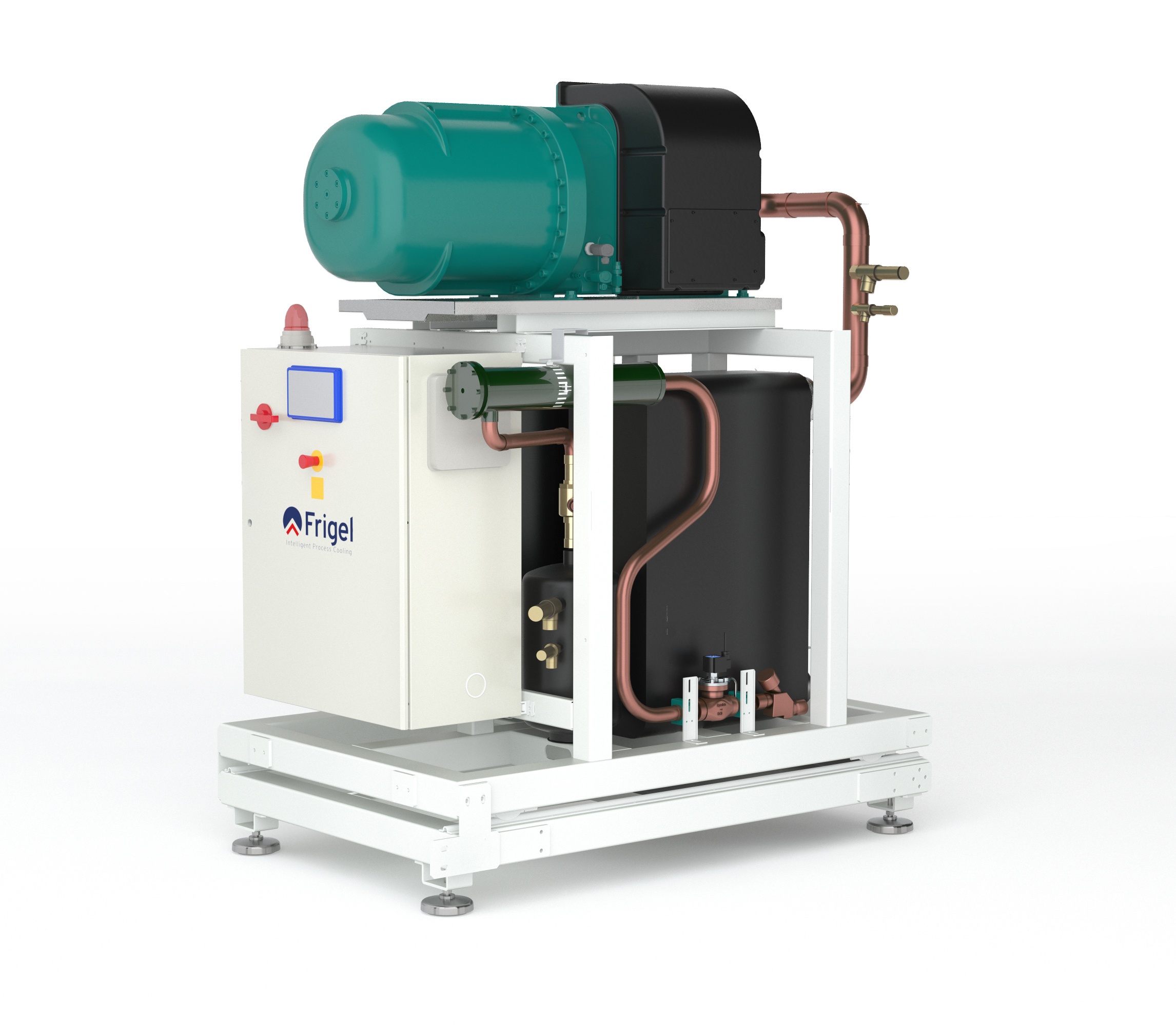
Frigel 3FX chiller
When compared to an evaporative cooling tower, chemical use can be reduced by as much as 40%, appealing to strict municipal water quality regulations while improving system reliability and uptime. Maintenance issues are also drastically reduced in comparison to open-loop systems. Contamination, corrosion, and deposits are all threats to machine performance. By reducing opportunities for cooling coils to interact with moisture, and cooling water exposure to the open air, maintenance-intensive issues are lessened. As a result, production uptime is optimized.
The closed loop-adiabatic cooler system also allows for greater free-cooling opportunities. When ambient conditions are appropriate, localized chillers are bypassed. Instead, heat is transferred to the air via copper tubes in the adiabatic chamber of the fluid cooler, and the cooled water is returned to the furnace vessel. Meanwhile, localized chiller compressors are automatically shut down, saving energy and reducing costs. Working together, the closed-loop adiabatic cooler system and localized chillers are able to provide cooling water temperatures at a wider range of ambient conditions, allowing greater flexibility throughout the heat-treating process.
Additionally, an Intelligent Process Cooling system provides a modular solution. With the fluctuation of job demands and shifting job requirements, the system can expand to fit each unique process cooling need. The use of dedicated chillers allows work cells to be self-contained, reducing disruption and downtime as new process cooling requirements adapt and develop with business growth.
Applying the Intelligent Process Cooling System
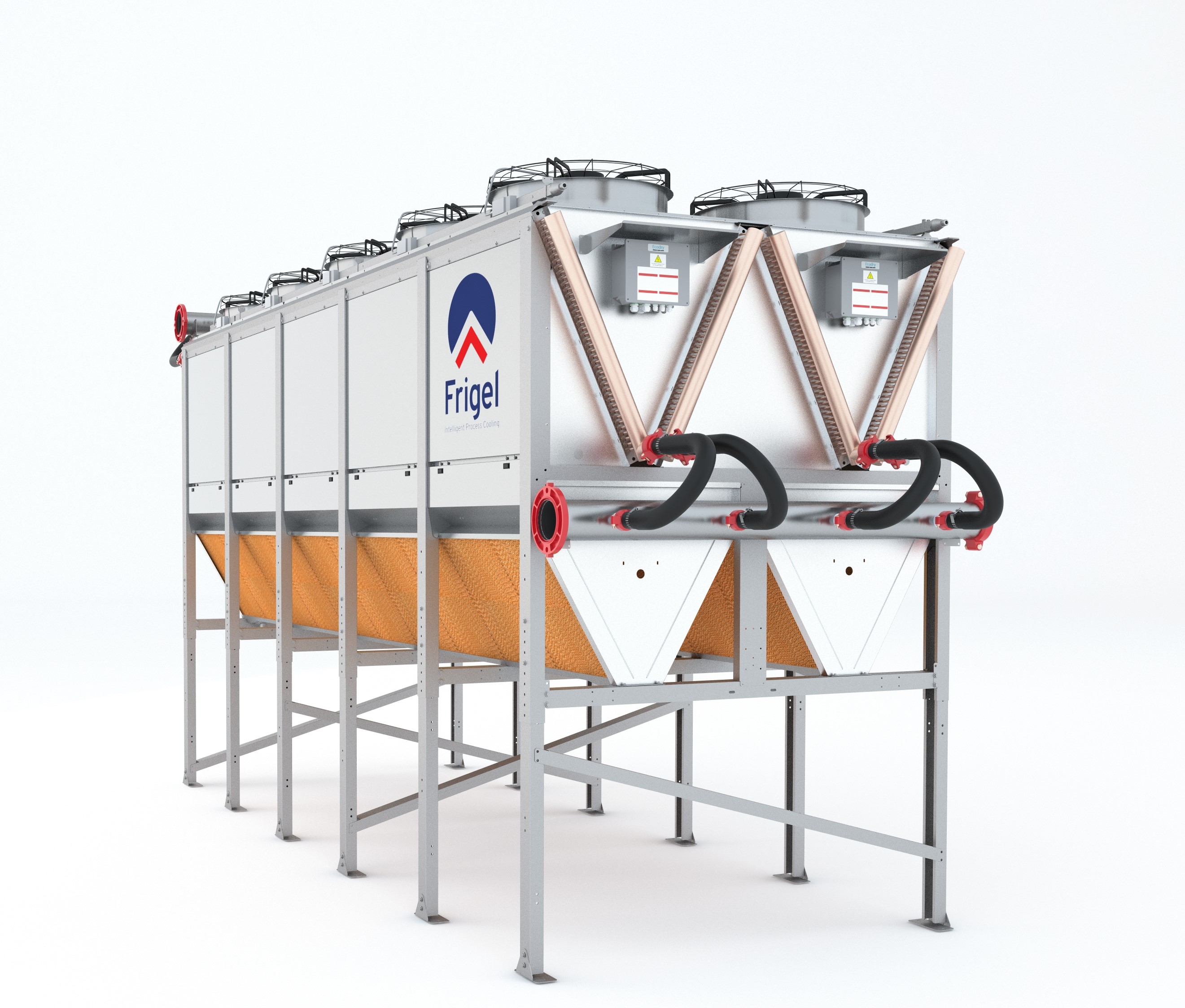
At the East Coast manufacturer’s operation, a Frigel Ecodry internationally patented closed-loop adiabatic fluid cooler operates outside the facility. The Ecodry unit is used in combination with dedicated Frigel 3FX water-cooled chillers inside the facility to maximize opportunities for free cooling while ensuring consistent and reliable process cooling temperatures.
At the alloy manufacturer, the Intelligent Process Cooling system installed includes an Ecodry fluid cooler with a patented adiabatic chamber and several water-cooled chillers.
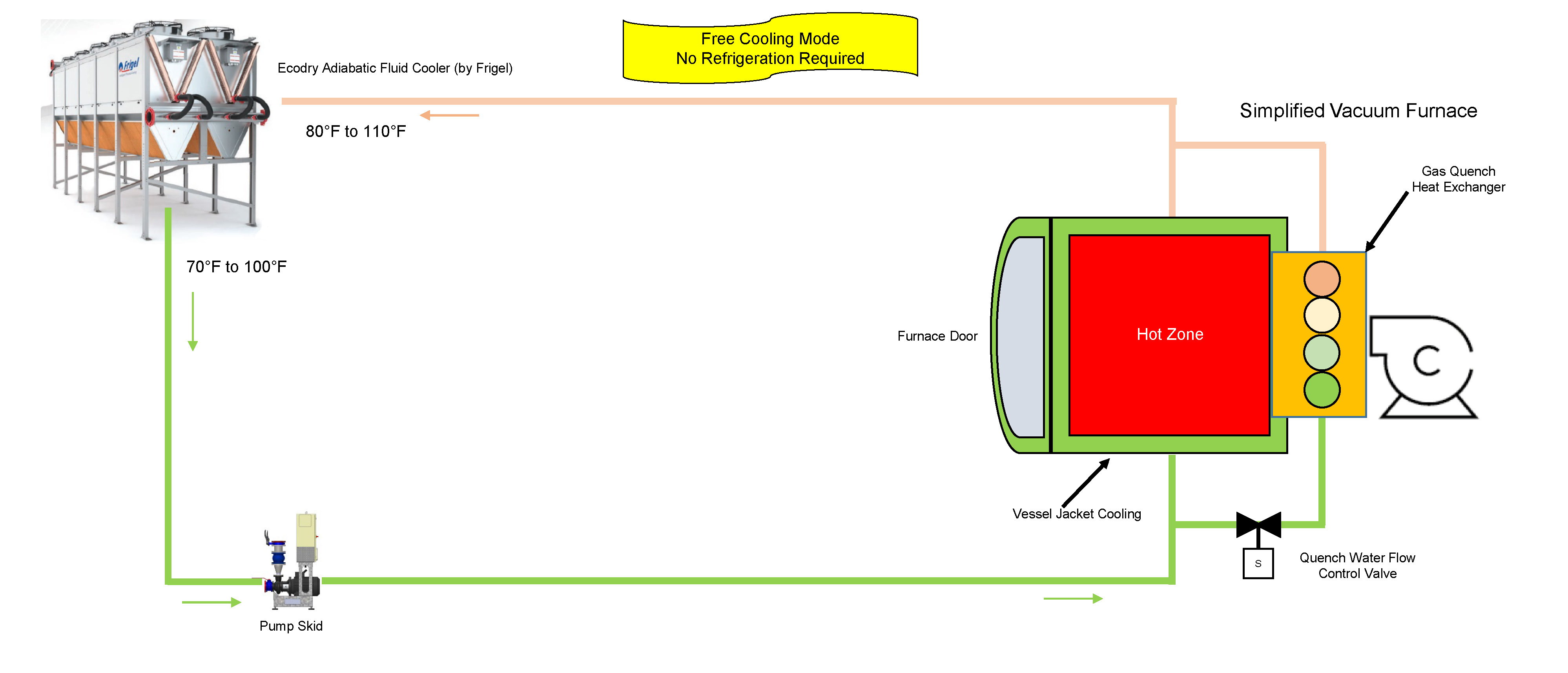
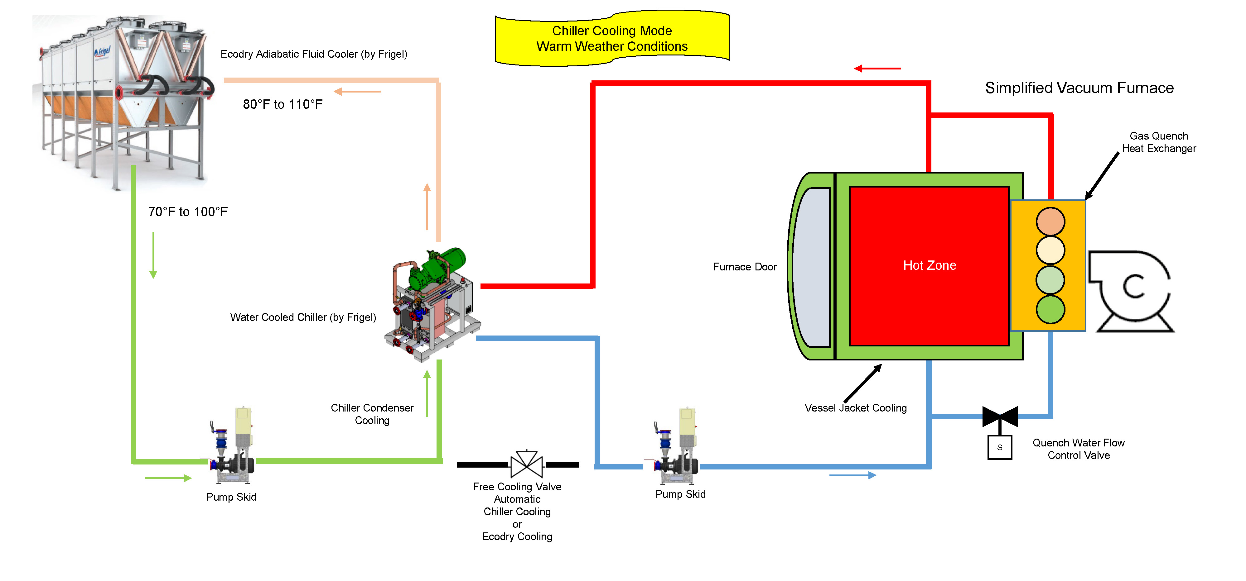
Throughout the year, this system leverages free cooling when ambient conditions permit (see Figure 1). For this manufacturer, the installation location provides ambient temperatures that are quite mild, reducing the necessity for localized chillers from approximately the beginning of October to the end of April. Instead, process cooling water transfers heat to the ambient air via the copper tube and aluminum coils in the adiabatic fluid cooler. Once cooled, water travels to the pump skid, then returns to the furnace vessel where it cools the furnace jacket, furnace door, diffusion pump, and heat exchanger.
Figure 1. The Frigel Intelligent Process Cooling system leveraging free-cooling opportunities.
While the furnace is in processing mode, process cooling water runs between the shells of the vacuum, cooling the inner walls, furnace jacket, furnace door, and diffusion pump. This ensures the furnace exterior maintains a safe temperature and the diffusion pump is able to sustain necessary atmospheric pressure within the furnace vessel. Following the completion of the processing cycle, the quench water flow control valve sends process cooling water to the heat exchanger, decreasing furnace vessel temperatures to the desired temperature for part handling and extraction.
Existing water-cooled chillers supplement the cooling process during the rest of the year when set temperatures can no longer be maintained with the use of free cooling (see Figure 2). When temperatures are at their highest, the water-cooled chillers generate the 70°F coolant and the heat is transferred to the Ecodry loop via the chiller condensers. From there, the chilled water travels to the furnace vessel, cooling the furnace components. Once the water has passed through the process, it returns to the adiabatic fluid cooler, and the water-cooling process begins once again.
Figure 2. The Frigel system leverages chiller cooling mode in warm weather conditions.
If and when ambient temperatures exceed 85°F, the adiabatic chamber of the fluid cooler initiates the spray system to lower incoming air temperatures closer to the wet-bulb temperature. By doing so, the coolant is lowered to a temperature that maintains reliable, efficient operations.
Operational Savings of $80,000 Per Year and More
By leveraging a closed-loop system with an adiabatic chamber, the alloy manufacturer achieved benefits that weren’t possible with traditional technologies. Chiller run time is in the 1,500 hour-per-year range and adiabatic cooling is required less than 400 hours per year. Compared to an evaporative cooling tower and water-cooled chiller system, water use has been reduced by 95% and electrical energy costs have been reduced by 60%. Increased efficiencies and reduced water consumption have resulted in operating costs that are dramatically less than any other system. In total, the plant saves over $80,000 per year with the Frigel system.
For this manufacturer, an alternative solution to traditional process cooling technologies was the only viable option. High costs drove innovation and a need for a better approach. Frigel’s Intelligent Process Cooling system, leveraging the capabilities of a closed-loop adiabatic system and localized water-cooled chillers, allowed for greater operational flexibility while reducing costs and maximizing efficiency—providing the manufacturer with a better process cooling solution.
About the Author
Gary Burgardt, Frigel North America’s market development manager, works closely with prospects and customers to ensure every Frigel process cooling solution delivers measurable results based on each company’s unique processes and business goals. In addition to expertise in Intelligent Process Cooling, Burgardt leverages 30 years of experience in process cooling across a wide range of industries to assist customers at every stage of the planning and buying process.
This article was written by Dr. Vadims Geza, chief scientist at CENOS. More information on CENOS Platform can be found here.
Induction is becoming an increasingly popular choice for heating steel billets prior to forging due to its ability to create high heat intensity quickly and within a billet, which leads to low process-cycle time (high productivity) with repeatable high quality, occupying minimal space on the shop floor. It is more energy-efficient and inherently more environmentally friendly than most other heat sources for steel billets.
In this article, the author demonstrates a simulation example on how to optimize a progressive induction heating system for a steel billet. The method used is CENOS Platform, a 3D simulation software which focuses specifically on induction heating and uses open source components and algorithms.
CENOS platform is capable of simulating various types of induction heating for forging. It is possible to simulate both static heating and progressive heating where the billet is moved through the coil with constant velocity. In accomplishing this simulation, coil design is not a limitation: both single coil and multi-coil are possible to simulate. Besides the coil, it is also possible to simulate any material and frequency.
The functional performance of the software
CENOS is a finite element method-based, computer-aided engineering desktop software for 2D and 3D physical process simulation and computational modeling of induction heating, induction hardening, brazing, annealing and tempering of steel, aluminum, copper, and other materials.
The simulation process consists of three steps:
Choose the workpiece geometry (from built-in templates or create your own CAD file).
Define induction heating parameters (frequency, voltage, time, etc.).
Run 2D or 3D simulation of your choice.
At the conclusion, results like temperature and magnetic field are displayed in 3D renderings, plots, and more. Apparent power, induced heat, and inductance are logged into an Excel file.
3D Simulation example—comparison of two heating systems
In the simulation, two systems under consideration—two-stage and three-stage systems—in the progressive heating of the billet. The target for the simulation was to reach 2192°F (1200°C) ± 122°F (50°C). To check both systems, the user has to create set up for both of them, set physical parameters (material properties, frequency, current, etc.), and start the simulation.
After the simulation is done, the user will have access to different output variables, including:
Temperature distribution
Current density and Joule heat distribution
Magnetic field lines
Total, reactive and apparent power
Inductance of the coil
Coil current, voltage
In our example of billet heating, it is possible to compare both cases and the output.
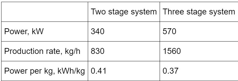
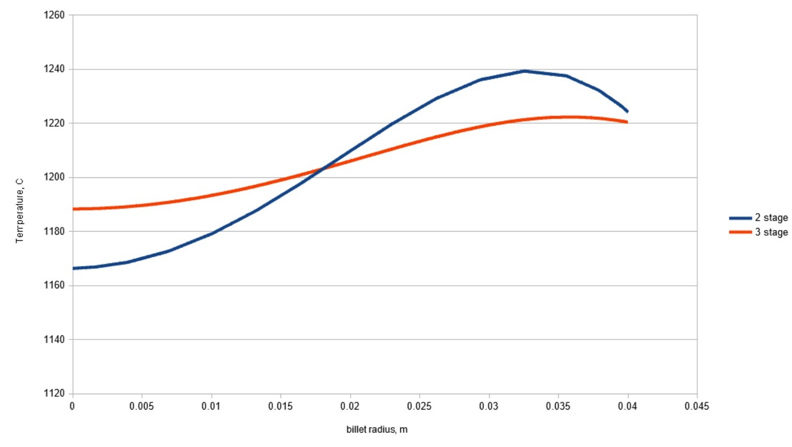
It is observable how a three-stage system can decrease power consumption and increase the production rate for this specific case. It is also possible to plot the distribution of temperature, Joule heat, magnetic field, etc. Resulting temperature distribution in the billet across the radius is shown in Figure 1. As can be seen, better temperature homogeneity is obtained in the three-stage system.
Figure 1. Temperature distribution along the billet radius at the outlet of the heating system
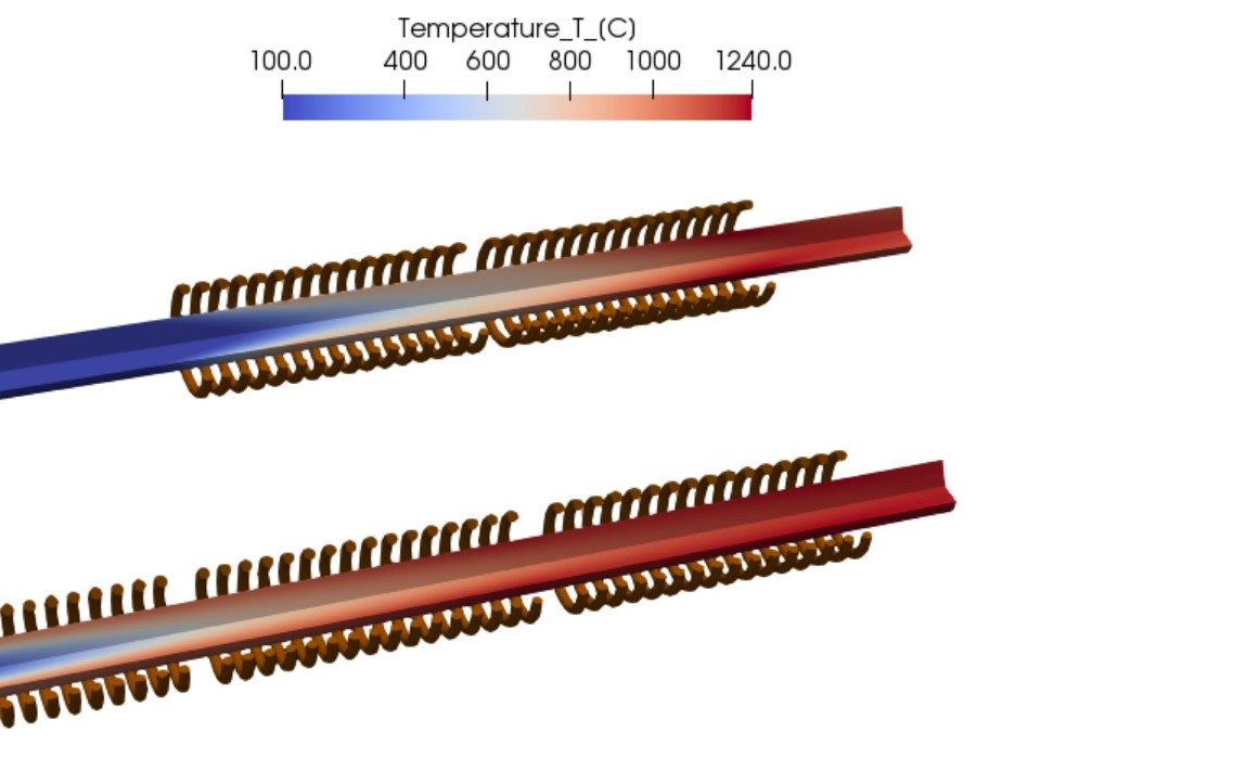
Figure 2. Temperature distribution in the long billet during scanning (progressive) induction heating.
Figure 2 shows how different systems lead to different temperature distribution. In the two-stage system, the temperature required for forging is reached with shorter coils, thus also with smaller scanning speed. This leads to worsened temperature uniformity and smaller production rates. On the other hand, the three-stage system heater gradually increases the temperature of the billet and the resulting temperature difference between core and surface is smaller.
Platform users are free to change all the input parameters and assemble the system of any number of stages required for their process.
Should the same system need to be used for scanning of shorter billets where end effects play a more significant role, it is possible to set up a simulation with a moving billet. An example of temperature dynamics in such simulation are shown in GIF images below:
A simulation with a moving billet in a two-stage system.
A simulation with a moving billet in a three-stage system.
Simulation helps make better decisions for production set-up and planning
As demonstrated in the simulation example, it is possible to compare two different systems and get results. The scope and variety of different simulations are unlimited; it all depends on what problem the user wants to solve:
Dr. Vadims Geza
Heating system design—to optimize induction heating performance, improve product quality, and avoid unpleasant surprises related to subsurface overheating
The selection of power, frequency, and coil length in induction billet heating applications
The selection of right forging temperatures for plain carbon and alloy steels to avoid possible damage by incipient melting or overheating.
Main Photo Image via CENOS, courtesy of efd-induction.com


 Source: Vac Aero International Inc.
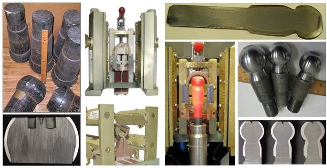
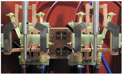
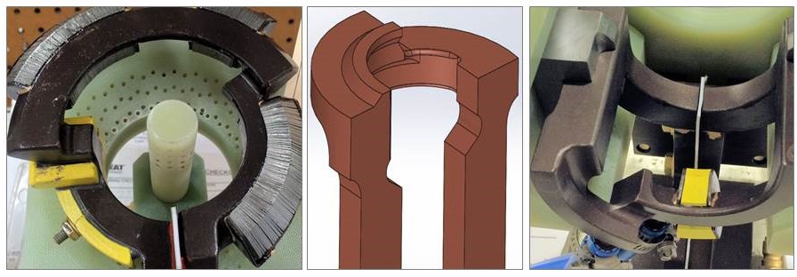

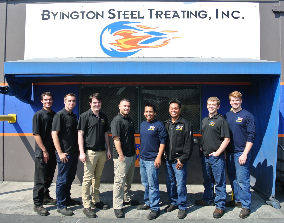

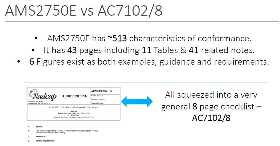

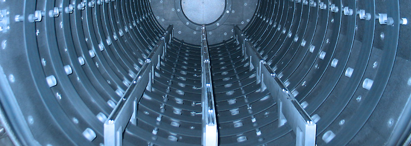


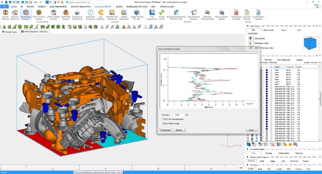


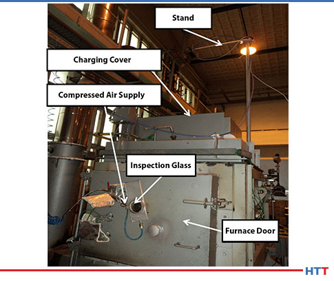
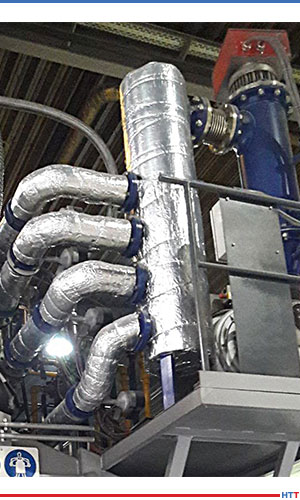
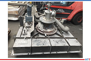

 Discolored Part—Who’s to Blame?
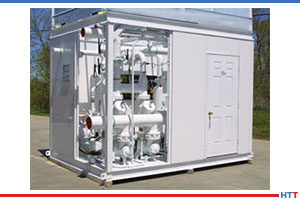
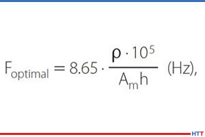
 AMS2750 Is Golden