Discover expert tips, tricks, and resources for sustainable heat treating methods Heat Treat Today's recent series. And, if you're looking for tips on combustion, controls systems, or induction in general, you'll find that too! Part 1, today's tips, digs into cleaning and maintenance
This Technical Tuesday article is compiled from tips in Heat Treat Today's May Focus on Sustainable Heat Treat Technologiesprint edition. If you have any tips of your own about induction and sustainability, our editors would be interested in sharing them online at www.heattreattoday.com. Email Bethany Leone at bethany@heattreattoday.com with your own ideas!
1. Maintenance of Induction Coils Used in Hardening Applications
Contact us with your Reader Feedback!
Soap and hot water will remove sticky quench and debris. Source: Induction Tooling, Inc.
How should you maintain induction coils used in hardening applications? Elbow grease — a little goes a long way. After each use, a simple solution of soap and hot water will remove sticky quench and debris. Scrub hardened dirt with a Scotch-Brite pad. Check for pitting, arcing, and insulator damage. If all is good, use a hot water rinse, and it’s ready for use. If the inductor is to remain on the machine for an extended period, it is advised to wash it and the associated bus daily. Check for damage. Following this simple procedure will reduce business waste.
As industry tries to become more “green,” a number of companies are switching from lubricants that are petroleum or mineral oil-based to water-based (“aqueous”) lubricants instead. However, some of these companies then make the mistake of not changing their degreasing fluids that they use to remove these lubricants prior to their next processing operations, and stay with their standard degreasing fluids, such as acetone or alcohol, which are not effective at fully removing water-based lubricants. Instead, they need to run tests to find an appropriate alkaline-based degreasing fluid for such water-based lubricants, since alkaline-based degreasers will be effective at removing such lubricants. Commonly available dish-detergents (alkaline-based) have been shown to be highly effective for such use.
Heat Treat Today’s Technical Tuesday feature means that on just about any given Tuesday, there will be an article that aims to educate our heat treating readers—be it in a process, equipment, metals, analysis, critical parts, or more. Enjoy this sampling of Technical Tuesday articles from the past several months.
Case Study: Heat Treat Equipment Meets the Future Industry Today
Contact us with your Reader Feedback!
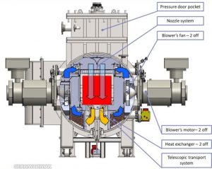
Construction and schematic furnace cross-section CMe-T6810-25 Source: SECO/WARWICK
How has one heat treat furnace supplier contended with modern challenges of manufacturing? In this case study about a shift away from traditional forms of heat treat, explorehow vacuum furnace technology has more technological horizons to bound.
Several key features discussed will be the various challenges that characterize modern industry; the differences between historical heat treat furnaces and vacuum furnaces; furnace features that can meet these obstacles; and a close look at what one equipment option from SECO/WARWICK helps. Additionally, explore the case study of a process that resulted in the following assessment: "all technological requirements have been met, obtaining the following indicators of efficiency and consumption of energy factors calculated for the entire load and per unit net weight of the load (700 kg)."
Eric Yeager of Cleveland Electric explaining the 101 of all things thermocouple Source: Heat Treat Today
How do thermocouples work? How would you tell if you had a bad one? Those ever present temperature monitors are fairly straightforward to use, but when it comes to how it works — and why — things get complicated.
This transcript Q&A article was published in the print edition last year (2022), but there was too much information to fill the pages. Online, read the full-length interview, including the final conversation about how dissimilar metals create EMF. Included in the discussion is proper care of the T/C and knowledge of when it’s time to replace.
Trends in the heat treat industry Source: Unsplash.com/getty images
What’s “hot” for heat treaters in recent months? The trends are pointing towards streamlining upgrading information systems, more efforts to reduce carbon footprint, and ensuring processes in salt quenching and electricity use are as efficient as they can be.
Each of the 6 trends included in the article demonstrates that heat treaters are making thoughtful and responsible decisions and purchases. Considerations include care for the environment and methods to help employees share and receive information needed for each job.
Read more about each of the trends to see what’s happening with equipment purchases and technology decisions and how companies are pushing to make that carbon footprint smaller.
A Quick Guide to Alloys and Their Medical Applications
Sneak peak of this medical alloys resource Source: Heat Treat Today
If you're pining for a medical heat treat quick resource in our "off-season," we have a resource for you. Whether you are a seasoned heat treater of medical application parts or not, you know that the alloy composition of a part will greatly determine the type of heat treat application that is suitable. Before you expand your heat treat capabilities of medical devices, check out this graphic to quickly pin-point what alloys are in high-demand within the medical industry and what end-product they relate to.
The alloys addressed in this graphic are: titanium, cobalt chromium, niobium, nitinol, copper, and tantalum.
Resource -- Forging, Quenching, and Integrated Heat Treat: DFIQ Final Report
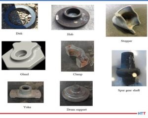
Examples of DFIQ equipment Source: Joe Powell
How much time and energy does it take to bring parts through forging and heat treatment? Have you ever tried to integrating these heat intensive processes? If part design, forging method, and heat treat quenching solutions are considered together, some amazing results can occur. Check out the report findings when the Direct from Forge Intensive Quenching (DFIQTM) was studied.
Forgings were tested, in three different locations, to see if immediate quenching after forging made a difference in a variety of steel samples. The report shares, “The following material mechanical properties were evaluated: tensile strength, yield strength, elongation, reduction in area and impact strength. Data obtained on the mechanical properties of DFIQ forgings were compared to that of forgings after applying a conventional post-forging heat-treating process.”
Consider the numerous systems in your heat treat operations. What makes up the anatomy of each furnace? In this "Anatomy of a Furnace" series, industry experts indicate the main features of a specific heat treatment system. For this inaugural feature, note how the schematics demonstrate how the tip-up furnace is able to process massive loads in an atmospheric sealed environment at highly controlled temperatures.
Contact us with your Reader Feedback!
Annotations for this furnace corpus were provided by Dan Herring, The Heat Treat Doctor®, The HERRING GROUP, Inc. A front view of a tip-up furnace as well as a back view of a different tip-up are provided along with the labels.
Download the full graphics by clicking the images below.
Click to download now!
This Technical Tuesday article is drawn from Heat Treat Today's February's Air & Atmosphere Furnace Systems print edition.
You can take the aircraft apart, but can you put it back together? Reverse engineering, as anyone who has ever taken apart the TV remote will tell you, is more complicated than it first appears. It is, however, far from impossible. Learn the essential steps to reverse engineering, the role of heat treating, and the challenges the thought process presents.
For this Technical Tuesday piece, take a few minutes to read Jonathan McKay's, heat treat manager at Thomas Instrument, article drawn from Heat Treat Today's March Aerospace Heat Treating print edition. Heat Treat Today is always pleased to share pieces from one of our 40 Under 40 alumnus like Jonathan!
If you want to share ideas about the aerospace industry, our editors would be interested in featuring it online at www.heattreattoday.com. Email Bethany Leone at bethany@heattreattoday.com with your own contributions!
Contact us with your Reader Feedback!Jonathan McKay
Heat Treat Manager at Thomas Instrument
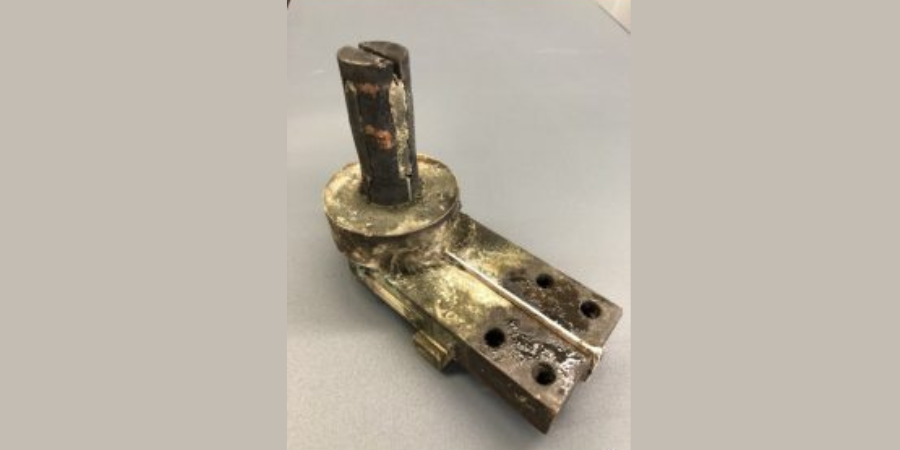
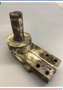
Source: Thomas Instrument
Reverse engineering (RE) is the process of taking a component or design and dissecting it all the way down to the raw material. Reverse engineering can range from a singular component such as a piston or gear, to multiple components that make up an overall assembly such as an engine or mechanical actuator. This process allows engineers to analyze and gain an understanding of a component’s overall function and design through deductive reasoning. RE can range in the type of analysis, from geometric measurements and material analysis to electrical or mechanical testing. Each analysis reveals clues of how something can be reproduced. The idea of reverse engineering is to look beyond what’s in front of you and find the unexposed clues that can show why something was designed or possibly the thought process of the original designer.
Reverse engineering typically happens through a third-party manufacturer usually not affiliated with the original equipment manufacturer (OEM). Often this is done because the original manufacturer no longer supports the product, or the original design is outdated and needs to be modernized to improve efficiency, functionality, or life expectancy. To put this in perspective, the U.S. Airforce received its first B-1 Bomber in 1984. Since then, over 100 aircrafts have been delivered. After nearly 50 years the aircraft is still flying, but many OEM manufacturers have moved on to newer programs, thus allocating their capabilities and capacity towards the present and future market demands. This creates a market for fabrication of replacement components and assemblies to support aging platforms. In most cases, the OEM’s retain proprietary data thus creating a need for RE processing.
"[T]he U.S. Airforce received its first B-1 Bomber in 1984.
Source: Unsplash.com/midkiffaries
With aerospace products in particular and specifically aging aircrafts, one will encounter obsolescence issues. The goal is to maintain the aircraft with replacement parts that conform to all form, fit, and function requirements while also assuring they have proper life expectancy with respect to maintenance cycles. With this in mind, you typically work with low volume production and invest more time into the design and planning phase of the process. When engaged in this process, it is critical that one understands and implements a fabrication plan that will yield a product that is equivalent or better than that of the OEM. Some engineers would say “Well, let’s make it bigger and better,” but with aerospace components this is not always the case. Typically, the main focus is to replicate the original design intent to the best of your ability because you have a specific footprint and weight to maintain as well as functionality. The exchangeability of the original design and RE design is key. The reverse engineered product needs to possess the same functional and physical characteristics and be equivalent in the performance, reliability, and maintainability. This allows both items to be exchanged without concern for fi t, performance, or alterations to its adjoining component(s).
Another key point in RE processing could be to limit long lead phases by minimizing the need for additional qualification testing where possible. As plating, heat treat, or materials begin to deviate from the initial design, you must consider requalification testing to prove those changes are not detrimental to the application and do not cause more harm than good. Sometimes engineers create features within a design that are meant to be a weak point; this prevents a more critical component from breaking or being destroyed. When you begin to make deviations, it may push the weak point closer to the critical component.
While there are certainly many steps to RE, the essential steps include:
Collect as much data as possible from an external standpoint without destroying or disassembling; i.e., note the overall measurements, orientation, special features, electrical or mechanical properties, etc. It is also a good idea to analyze mating components and/or the system in which the component is utilized. Mating parts are a big part of the discovery; the mating parts can help determine what alternate materials, plating, heat treat, or finishes can be used.
Start creating preliminary drawings with detailed dimensions, notes, and features that were inspected from Step 1.
Slowly disassemble the part (if an assembly) and inspect key features and create preliminary drawings for sub-assembly components. In some cases, it helps to reassemble the product to ensure an understanding of how it goes back together in order to optimize the assembly process once new components are manufactured.
Evaluate the product(s). Conduct material analysis to acquire chemical and mechanical property data. This will aid in defining the appropriate layout for machining, material conditioning (i.e., heat treatment), external finishes/coatings, etc.
While the design and planning phase may pose some challenges, the more critical challenges that occur during reverse engineering are in the execution of the manufacturing, assembly, and qualification testing. To elaborate, once you begin machining and processing components, there may be special methods of manufacturing that require discovery because standard methods may not have worked when the OEM produced it. When this happens, you go back and forth on updating and fine-tuning the process plans, fixturing, programs, etc. Sometimes this means scrapping parts and starting over or validating if parts are still usable for prototyping. Along the same lines, when the process progresses into the assembly and testing phase, engineers typically discover variability, errors, or weak points that require adjustments. In those cases, the engineer’s drawings must be revised. A large percentage of these issues can be limited through experience with similar components or assemblies, but in most cases, there is a lot of analysis and some trial-and error involved in the manufacturing, assembly, and testing phase that is not apparent upon initial RE processing.
References:
Boeing. “The Bone.” https://www. boeing.com/defense/b-1b-bomber/
DLA. “Master List of Technical and Quality Requirements Version 14.”
MIL-STD-280A. “Handbook for definitions of item levels, item exchangeability, models, and related terms.”
DOD Washington, D.C. 20301.
Special thanks to David V. Jones and Thomas R. Blackburn IV at Thomas Instrument for their input on this topic.
About the Author:
Jonathan McKay is a mechanical engineer at Thomas Instrument, a company specializing in reverse engineering critical aerospace components. At the company, he is manning the establishment of heat treat operations, has created procedures and process plans for Thomas Instrument to be an approved heat treater for an aerospace prime, and has attained Nadcap accreditation for heat treat.
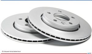
Are your brake rotors heat treated? Travel back in time to discover how ferritic nitrocarburizing (FNC) became the heat treatment of choice for automakers’ brake rotors and why the tip-up furnace forever altered the production process for this part.
This Technical Tuesday article is drawn from Heat Treat Today's February Air & Atmosphere Furnace Systems print edition.If you have any information of your own about heat treating brake rotors, our editors would be interested in sharing it online at www.heattreattoday.com. Email Bethany Leone at bethany@heattreattoday.com with your own ideas!
The Problem: Brake Rotor Corrosion
Michael Mouilleseaux General Manager at Erie Steel, Ltd. Sourced from the author
In the early 2000s, corrosion was one of the top three issues that U.S. automotive manufacturers found negatively affected the perception of the quality of their cars. Brake rotors are made of cast iron. These components sit out in the elements, and in places like the U.S. Midwest where salt is often used on the roads, unprotected steel or iron will corrode or rust. Even on the coast, there is salt water in the air.
Contact us with your Reader Feedback!
What does rusting cause? The rotor rusts, and first, the cosmetics are negatively affected (i.e., rusty appearance). But more importantly, the first time you step on the brakes, it squeals like a pig, the vehicle shudders, and the driver feels pulsing in the pedal. He’ll also feel it in the steering wheel because the amount of rust coating one area is different from the amount of rust that’s on another. So, these brand new, forty- to seventy-thousand-dollar cars have orange rust over the brake rotor and a shaky drive. . . it’s not a good look!
Now, this is just a superficial coating of rust that will eventually abrade away; the rotor will look alright, the vehicle will stop better, and it won’t squeal. However, since the rust on the rotor wears off unevenly, the car may never have smooth braking.
A Move to FNC
In the early 2000s, all the big players were looking to FNC (ferritic nitrocarburizing) as a solution to corrosion, including Bosch Braking Systems, Ford, General Motors, Akebono, and the truck manufacturers. FNC was becoming popular since the process adds a metallurgical layer — called the “white layer” or “compound zone” — to the part, providing corrosion resistance and the bonus of improving wear.
Source: Oleksandr Delyk/Adobe Stock
To the OEMs, the benefits were perceived as:
The corrosion issue had an answer.
The life of the rotor doubled from roughly 40,000 to 80,000 miles. Although that meant half as many aftermarket brake jobs compared to before, consumers perceived it as a real advantage.
The rotors generated less dust. Brakes generate dust particles as the result of abrasion of the pads and the rotors. This particulate dust has been identified as both an environmental and a health concern. Now, flash forward to 2022: Electric vehicles are largely displacing the need to control emissions from ICE (internal combustion engine) vehicles. So, the new European standard on vehicle emissions implemented a requirement to control this dust that is harmful to the environment and which EV and traditional brake systems can emit.
But there were certain technical and practical challenges that automotive manufacturers faced when trying to implement this process at scale.
#1 Distortion. Brake rotors may distort during FNC. Since rotors are (gray iron) castings, the process temperature for FNC may stress relieve the rotor, causing it to change shape or distort, rendering it unusable as a disc brake rotor. It was determined that if the rotor castings were stress relieved prior to machining and FNC, the distortion issue was rendered moot.
#2 Loss of Necessary Friction. FNC gives the white layer on the surface of a part with a diffusion zone underneath. The compound zone has a very low coefficient of friction, which means excellent wear properties. However, manufacturers want friction between the rotor and the brake pads to slow the car down. Reducing the friction on the rotors extends the braking distance of the car.
". . .[M]anufacturers want friction between the rotor and the brake pads to slow the car down." Source: Unsplash.com/Craig MorolfLet me illustrate this: I ferritic nitrocarburized a set of brake discs for Bosch Braking Systems, which eventually went to Germany and then on a vehicle. The customer absolutely loved the corrosion resistance, but when it was time for the downhill brake test, the car went straight through an instrument house because the brakes couldn’t stop the car! Lesson: For rotors treated with FNC, the brake pads need to be made from a different frictional material!
#3 Cost. Overcoming the technical issues is simple. Stress relieving the casting at FNC temperatures before machining it would help the parts machine better and would eliminate distortion. Modifying the FNC process could reduce the depth of the white layer and, paired with the correct friction material, the acceptable braking capabilities were restored. Yet these additional steps presented a new challenge: higher costs.
The practical constraints of FNC in conventional batch or pit furnaces strained efforts to be cost-effective. The load (size) capacity of the conventional equipment, in conjunction with the time constraints of the FNC process presented a dilemma, as the OEMs’ benchmark was about one dollar per rotor.
Here Comes the Tip-Up
With traditional furnaces for FNC, there was just no way to reach the economics that were necessary for it. A bigger pit furnace might be the way to go, but they really weren’t big enough. So, here comes the tip-up.
Traditionally, a tip-up furnace has been used for processes with just air, no atmosphere. With direct fired burners, the furnace is used for tempering, stress relieving, annealing, and normalizing. Everything loads into the box, gets fired, and unloads, similar to a car-bottom furnace. With the appropriate external handling systems parts could be retrieved from the furnace and then quenched. This additional process increased the usefulness of the equipment and allowed for the processing of tubes, bars, big castings. . . big forgings for the oil industry and the like.
The question of how to heat treat brake rotors on a large scale still needed to be answered. It required a large, tightly sealed furnace with atmospheric integrity for excellent temperature uniformity. In ferritic nitrocarburizing, the processing range is about 950°F to 1050°F. It is well known that properties vary significantly across the temperature range. And they needed to be optimized to create the appropriate frictional properties for the rotors.
So, the answer was: Let’s make a tip-up furnace that can be sealed for atmospheric integrity, has the appropriate temperature uniformity, and can circulate gas evenly. A lot of this would have to be iterative — create, test, compare, repeat.
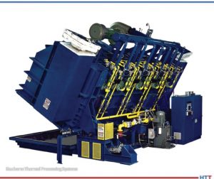
Tip-up furnace from Gasbarre Thermal Processing Systems Source: Gasbarre Thermal Processing Systems
The development of the perfect tip-up was essentially the work of one furnace manufacturer and one heat treater who together changed the industry.
American Knowhow Makes the Perfect Tip-Up
In the early 2000s, heat treaters worked with OEMs to develop a cost-efficient process in a tip-up. Manufacturers and service providers tested different methods, including atmosphere FNC and salt bath FNC.
By 2009, the perfect atmosphere furnace was complete and high volume brake rotors began to be processed for General Motors. The furnace manufacturer was JL Becker, Co., acquired by Gasbarre in 2011. The commercial heat treater was Woodworth, Inc., located in Flint, MI. Together, they spent a lot of time and money looking into FNC and figuring out how to make it work in a tip-up furnace.
General Motors was the first one to get on board, utilizing the FNC processed rotors on their pickup trucks and big SUVs, like the Escalade and Tahoe. Ford was not far behind using it on their F150 pickup truck. I was shocked the first time I saw the commercial: a Silverado pickup truck, out in the snow, and the speaker saying, “We now have an 80,000-mile brake system because of a heat treating process called FNC!”
It’s a great story of American knowhow and a collaborative effort between someone who saw a need and someone else who saw the way. To this day, if you want to get a replacement set of brake rotors for your car, go to a place like AutoZone; they will tell you that the difference in cost between the OEM parts and an off-brand is the fact that the off-brand is not heat treated.
About the author: Michael Mouilleseaux has been at Erie Steel, Ltd. in Toledo, OH, since 2006 with previous metallurgical experience at New Process Gear in Syracuse, NY, and as the Director of Technology in Marketing at FPM Heat Treating LLC in Elk Grove, IL. Having graduated from the University of Michigan with a degree in Metallurgical Engineering, Michael has proved his expertise in the fi eld of heat treat, co-presenting at the Heat Treat 2019 show and currently serving on the Board of Trustees at the Metal Treating Institute.
How clean is clean enough? Insufficient cleaning before heat treating can interfere with results; insufficient cleaning after heat treating can impact perception of the part. Discover four methods of measuring part cleanliness that can take place within your heat treat operations in this article provided by SAFECHEM Europe GmbH.
This Technical Tuesday article is drawn from Heat Treat Today's March Aerospace Heat Treatingprint edition. If you have any information of your own about cleaning after heat treating, our editors would be interested in sharing it online at www.heattreattoday.com. Email Bethany Leone at bethany@heattreattoday.com with your own ideas!
Previously we talked about the importance of cleaning for demanding heat treat applications — in particular gas nitriding, or ferritic nitrocarburizing (FNC), low pressure carburizing (LPC), and brazing. So, if cleaning is a nonnegotiable for certain heat treatment processes, one might ask: how clean is clean enough?
Contact us with your Reader Feedback!
The basic definition of clean is removing unwanted substances, particles, and contaminations. However, when applied to surface cleaning, “clean enough” is determined by what you want to do next in your processing. Parts are generally clean enough if satisfying outcomes can be achieved in the subsequent application.
First, Do You Know the Expectations?
Unlike measuring hardness, monitoring or determining part cleanliness is by no means a straightforward matter.
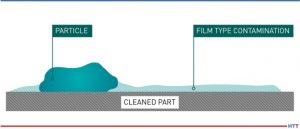
There are two different kinds of contaminations to consider:
Particle contaminations
Film-type contaminations
Types of contamination Source: SAFECHEM Europe GmbH
Whereas there are industry definitions or standards for particle contaminations (e.g., VDA-19 or ISO-16232 for the automotive industry), standards for film-type contaminations are not yet fully established.
This inadequacy also explains why many companies do not fully know what to expect when it comes to cleanliness, and they do not fully grasp the potential impact that insufficient cleaning could cause.
Especially when it comes to the heat treat industry, it is important to differentiate between the component cleanliness requirements before and after heat treatment.
Film-type contaminations are the primary factor which could negatively impact heat treat results. Requirements on particle contaminations (VDA-19) usually come from the automotive industry and need to be ensured/monitored after heat treatment.
Therefore, a distinction must be made between a) surface requirements for heat treatment and b) client cleanliness requirements on the final components.
What Is the Right Measurement Method?
The analysis of film-type contaminations and particle contaminations are two different subject matters. Measurement methods for one cannot replace the measurement methods for the other. Often, it is quite common for companies to have requirements on both film-type contaminations (e.g., surface energy in dyne/cm or mN/m) and particle contaminations (e.g., max. particle load) in their component drawings.
Some common measurement methods for determining contaminations include:
White wipe test: A simple visual inspection test using a clean and dry white wipe to wipe across the surface for the detection of colored residues. Because contaminations can negatively impact heat treat results, inspection should take place prior to heat treatment. The test is limited to colored particles whose size can be perceived by the eye.
Water break free test: An easy test to check if oil droplets might be present on the surface is when parts are rinsed with clean water at an angle. If there are contaminations, water will separate around those areas, showing a “break” in the water surface.
Dyne testing: This method is commonly used for measurements of film-type contaminations. Dyne inks and fluids are applied to a substrate for measurement of its surface energy. The surface energy (measured in dyne/cm or mN/m) can be identified as the highest dyne solution that wetted out the substrate surface. The higher the dyne level, the better the adhesion of the surface for painting, coating, or bonding. However, the test does not provide information on the types of contaminations present.
Millipore filter measurements/solvent extraction test: This measures surface contamination on parts as a weight per 0.1 m2. Samples are obtained by flushing the cleaned part with an organic solvent where particulates are collected on a filter disc (solvent will be evaporated off later). The test can determine the nature, number, sizes of particles, and if there are reflecting/ non-reflecting metallic particles. Moreover, oil film on parts can be measured after evaporation of the extraction solvent. For automotive, aerospace, or electrical, the level of cleanliness typically ranges between 0.01–0.001g per cm2.
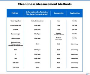
In general, these methods differ in their complexity and informative value, and also if they can be carried out on site or off site (e.g., in a laboratory). The table below provides an overview of common measurement methods:
Cleanliness measurement methods Source: SAFECHEM Europe GmbH
Determining Cleanliness — An Art and a Science in Itself
As you now see, the variances and potential limitations of different measurement methods can add to the complexity of cleaning validation. Consider the following:
Should you measure a specific surface area, or the entire part? And how do you measure pre-assembled components with different parts molded together?
It might be easy enough to measure surface cleanliness, but what about blind holes and crevices?
Visual inspections have many shortcomings. It is subjective, time consuming, and does not cover total level of contamination. The quality of inspection will very much depend on the operator. While automated particle counting is efficient and objective, it does not offer insights on specific contaminants.
Extraction methods targeting nonvolatile residues (NVR) can help determine a total level of contamination, but not spot contamination. It does not account for inextricable contaminants either, which could impact part functionality.
Meaningful Measurement Begins with Understanding the Big Picture
This is why, in order to measure and monitor cleanliness in a meaningful and reliable way, you should consider:
What potential contaminations could come about in your process/facilities?
What contaminants are you looking to remove?
What are the next processing steps?
What are the risks involved in removing the contaminants?
What are the risks associated with the potential residue?
Since every test has its own limitations, you should be mindful of the test specifications, too — for example, how it is conducted, result variability and reproducibility, as well as biases.
Cleaning can be a crucial step in heat treat, but more cleaning does not always equal better. More cleaning also implies more costs, more time, more resource usage. What’s really key is understanding what you, or your clients, are trying to achieve.
As you see, cleaning and measurement require expertise and knowhow — context is everything. Reach out to a cleaning specialist or trusted cleaning solutions expert for advice. If insufficient component cleanliness seems to be affecting your heat treat results, our cleaning specialists, along with our partners, would be happy to advise.
Let’s discover new tricks and old tips on how to best serve air and atmosphere furnace systems. In this series, Heat Treat Today compiles top tips from experts around the industry for optimal furnace maintenance, inspection, combustion, data recording, testing, and more. Part 4, today's tips, examines carbon probes and carbon control. Look back to Part 1 here for tips on seals and leaks, Part 2 here for burners and combustion tips, and Part 3 here for data and record keeping tips.
This Technical Tuesday article is compiled from tips in Heat Treat Today's February Air & Atmosphere Furnace Systems print edition. If you have any tips of your own about air and atmosphere furnaces, our editors would be interested in sharing them online at www.heattreattoday.com. Email Bethany Leone at bethany@heattreattoday.com with your own ideas!
1. Slight Positive Pressures Are Best
Contact us with your Reader Feedback!
Atmosphere furnace pressure should be only slightly above ambient. The range should be between 0.25-0.35 inches water column. Higher pressures in multiple zone pusher furnaces will cause carbon control issues. High pressures in batch furnaces will cause high swings when doors and elevators move.
If you’re having atmosphere problems with a furnace that has been operating normally for some time, avoid the temptation to remove the carbon probe. There are several tests you can run on nearly all carbon probes while the probe is still in the furnace, at temperature, in a reducing atmosphere. Super Systems Inc. provides an 11-step diagnostic procedure in a white paper on their website, in a paper titled, “Carbon Sensor Troubleshooting” by Stephen Thompson.
"Review process date for abnormalities." Source: Super Systems Inc.
Many factors can contribute to why parts are not meeting the correct hardness readings. According to Super Systems Inc., here is a quick checklist of how to start narrowing down the culprit:
Review process data for abnormalities. The first thing to do is make sure the parts were exposed to the right recipe. Check the recorders to make sure the temperature prof le and atmosphere composition were correct. Make sure all fans and baffes were working correctly. Determine if any zones were out of scope and that quench times were acceptable. If any red flags appear, hunt down the culprit to see if it may have contributed to soft parts.
Check the generator. Next, check the generator to make sure it is producing the gas composition desired for the process. If available, check the recorders to make sure the gas composition was on target. If not, check the generator inputs and then the internal workings of the generator.
Check the furnace atmosphere. If the generator appears to be working correctly, the next step would be to check the furnace itself for atmosphere leaks. Depending on what type of furnace you have, common leak points will vary; for continuous furnaces, common leak points are a door, fan, T/C, or atmosphere inlet seals. Other sources of atmosphere contamination may be leaking water cooling lines in water-cooled jackets or water-cooled bearings. More than likely, if the generator is providing the correct atmosphere but parts are still soft, there is a leak into the furnace. This will often be accompanied by discolored parts.
Check carbon controller to make sure it matches furnace atmosphere reading (verify probe accuracy and adjust carbon controller). This can be done using a number of different methods: dew point, shim stock, carbon bar, three gas analysis, coil (resistance), etc. Each of these methods provides a verification of the furnace atmosphere which can be compared to the reading on the carbon controller. If the atmosphere on the carbon controller is higher than the reading on the alternate atmosphere check, that would indicate the amount of carbon available to the parts is not as perceived. The COF/PF on the carbon controller should be modified to adjust the carbon controller reading to the appropriate carbon atmosphere. If the reading is way off, it may require the probe to be replaced.
Let’s discover new tricks and old tips on how to best serve air and atmosphere furnace systems. In this series, Heat Treat Today compiles top tips from experts around the industry for optimal furnace maintenance, inspection, combustion, data recording, testing, and more. Part 3, today's tips, examines AI and record keeping. Look back to Part 1 here for tips on seals and leaks and Part 2 here for burners and combustion tips.
This Technical Tuesday article is compiled from tips in Heat Treat Today's February Air & Atmosphere Furnace Systems print edition. If you have any tips of your own about air and atmosphere furnaces, our editors would be interested in sharing them online at www.heattreattoday.com. Email Bethany Leone at bethany@heattreattoday.com with your own ideas!
1. Use AI To Simplify Your Maintenance
Contact us with your Reader Feedback!
"cloud view of heat treating operation" Source: NITREX
Simplify your maintenance! Today, using artificial intelligence (AI) software allows the “Cloud” to do the hard work. NITREX has introduced QMULUS, a web-based software solution, with each of its nitriding systems, which examines key parameters to determine if your furnace is having any issues. Gas flows, amperage, motors, and cycles are all monitored for health factors. But QMULUS is so much more than that. It also analyzes input usages and calculates the cost of each run; logs all data relevant to running processes more efficiently; and provides an easy and seamless cloud view of heat treating operations.
This is a very simple tip that is often overlooked when customers are focused on meeting production goals instead of the maintenance of their equipment. It is critical to record the operating settings of their furnace systems when parts are coming out at their best, or simply before issues arise. When something goes awry in the process and troubleshooting is required, service technicians hear all too often that there is no record of what the ideal or correct setpoints are for various systems. Nearly every item on a modern heat treating furnace (or in its control panel) has a setpoint or position that can be recorded or physically marked. Now, clearly some items are more critical than others when it comes to air and atmosphere settings. Below are a few items you’ll want to have setpoint/positioning records of before they require troubleshooting:
Flowmeter setpoints (at the furnace and generator)
Blower/pump/motor VFD setpoints (primarily frequency setpoints and ramp rates)
Manual or actuated damper positions on flues
Regulator setpoint (from pressure gauge or in-line test port)
High/low pressure switch setpoints
Any air/gas/atmosphere ratios for various recipe steps
Burnout frequency and duration (if applicable)
An added incentive to record these settings is the preventative maintenance benefit. The best way to avoid supply chain issues and delivery delays is to fix a problem before it grows into a bigger issue. When a setpoint/setting is correct but product quality begins changing, it is a warning sign that consumables may be approaching end of life (such as nickel catalyst in endothermic gas generators) or components require maintenance (such as air inlet filter replacements).
Let’s discover new tricks and old tips on how to best serve air and atmosphere furnace systems. In this series, Heat Treat Today compiles top tips from experts around the industry for optimal furnace maintenance, inspection, combustion, data recording, testing, and more. Part 2, today's tips, examines burner and flame safety. Look back to Part 1 here for tips on seals and leaks.
This Technical Tuesday article is compiled from tips in Heat Treat Today's February Air & Atmosphere Furnace Systems print edition. If you have any tips of your own about air and atmosphere furnaces, our editors would be interested in sharing them online at www.heattreattoday.com. Email Bethany Leone at bethany@heattreattoday.com with your own ideas!
1. Operating with a Multiple Burner System
Contact us with your Reader Feedback!
If a furnace or oven has a multiple burner combustion system with only one valve train, a multi-burner combustion safeguard should be used. This ensures that if one burner fails, they all go out.
Source: Bruce Yates, "Ten Tips for Safeguarding Combustion Processes"
#multiburner #combustion #safety
2. Regularly Inspect Retort Alloys
Source: Nitrex
Retort alloys must be inspected on a regular basis. Hot spots can be identified by bulges. Plastic deformation occurs due to overheating, causing the hotter section to bulge because it is surrounded by stronger metal. Inspect your retorts or radiant tubes for deformations. In addition, constant thermal cycling can cause problems with some alloys. Look for cracks in welds or near welds. Some leak detection methods can also detect alloy issues or overheating.
Localized overheating could indicate a problem with the burner or the heating element. Early detection and correction can save you a lot of money on expensive alloys.
Flame supervision may be defined as the detection of the presence or absence of flame. If a flame is present during the intended combustion period, the supervisory system will allow a fuel flow to feed combustion. If the absence of flame is detected, the fuel valves are de-energized.
This basic definition does not consider the hazard potential during startup or ignition, however. A dangerous combustible mixture within a furnace or oven consists of the accumulation of combustibles (gas) mixed with air, in proportions that will result in rapid or uncontrolled combustion (an explosion). It depends on the quantity of gas and the air-to-fuel ratio at the moment of ignition.
Source: Bruce Yates, "Ten Tips for Safeguarding Combustion Processes"
#flamedetection #combustion #valves
4. Remember that Flame Safety Starts with Purging
The sequence for flame safety starts with purging the furnace or oven. Purge time should allow for four air changes.
Fuel valves can — and do — leak gas. The purpose of purging is to remove combustible gases from the combustion chamber before introducing an ignition source. The four air changes in the combustion chamber are based on a worst-case scenario that includes having a burner chamber that is completely filled with gas.
Once airflow for purge is verified, the proof-of-valve closure is confined and safety limits are proven. Then the purge timer — which may or may not be integral to the combustion safeguard — determines the period of time required to evacuate the combustion chamber.
Source: Bruce Yates, "Ten Tips for Safeguarding Combustion Processes"
Let’s discover new tricks and old tips on how to best serve air and atmosphere furnace systems. In this series, Heat Treat Today compiles top tips from experts around the industry for optimal furnace maintenance, inspection, combustion, data recording, testing, and more. Part 1, today's tips, examines seals and leak points.
This Technical Tuesday article is compiled from tips in Heat Treat Today's February Air & Atmosphere Furnace Systems print edition. If you have any tips of your own about air and atmosphere furnaces, our editors would be interested in sharing them online at www.heattreattoday.com. Email Bethany Leone at bethany@heattreattoday.com with your own ideas!
1. Tip-Up Furnace Perimeter Insulation Maintenance Is Key to Efficiency & Quality
Contact us with your Reader Feedback!
Due to their construction, the insulation at the perimeter of a tip-up furnace is subject to more abuse than typical furnace insulation. Whether from the repeated stress of cycling the case open and closed — or from high temperature operation — fiber modules will eventually begin to shrink/compact. Be watchful for high case temperatures (or worse: case discoloration and paint damage) as a signal that insulation issues are present in that area.
Heat-damaged case wall Source: Premier Furnace Specialists
An air/atmosphere tight seal is critical for maintaining heating efficiency and process quality. Inspect the seal material around the furnace perimeter often and replace sections that are worn. Common perimeter seals are sand seals, fiberglass tadpole tapes, and insulating fiber blankets. These sealing materials are easy to keep on hand to ensure a quality seal is never delayed by lengthy lead times or supply chain issues.
Seals are everywhere on any furnace. Do you know where all the seals and leak points are? Rope gaskets is an obvious example; high temperature gaskets need to be flat, smooth, and unbroken. Another clear example is in the world of vacuum furnaces: O-rings need to be clean and protected from abrasion. Almost every item of your furnace is sealed in some manner. It is best to replace seals as part of a preventative maintenance program. While your nose can detect ammonia, vacuum leaks require special helium leak detectors and a lot of training. Your furnace manufacturer’s service technician can assist in identifying problem areas and developing a maintenance routine to keep your furnace running. And a simple electronic manometer is great to have handy for running leak-down tests using positive pressures. Auto supply stores sell inexpensive halogen detectors, and some people use smoke bombs to detect leaks.


 Find heat treating products and services when you search on Heat Treat Buyers Guide.com