Tech Tuesday

¿Cómo elegir el termopar correcto en Tratamientos Térmicos?

OCLos termopares: elementos indispensables para lograr un acertado tratamiento térmico, pero ¿cómo elegir el más indicado para su necesidad particular? ¿Qué exigen las normas actuales? A continuación una explicación, por Víctor Zacarías, director general de Global Thermal Solutions México, que le ayudará a saber escoger el termopar adecuado.

Palabras clave: Termopar, Tratamiento térmico, Pirometría, Medición y Control de Temperatura, AMS2750, CQI-9

Read the Spanish translation of this article in the version below, or see both the Spanish and the English translation of the piece where it was originally published: Heat Treat Today's February's Air & Atmosphere Furnace Systems print edition.

Si quisieras aportar otros datos interesantes relacionados con los termopares, nuestros editores te invitan a compartirlos para ser publicados en línea en www.heattreattoday.com. Puedes hacerlos llegar a Bethany Leone al correo bethany@heattreattoday.com


Víctor Zacarías
Director General
Global Thermal Solutions México

La norma aeroespacial SAE AMS2750 y las evaluaciones automotrices de AIAG CQI-9, CQI-11, CQI-12, y CQI-29 son los estándares universalmente aceptados para el control de temperatura en operaciones de procesamiento térmico. Entre muchas cosas, describen los requisitos para el uso y control de los termopares empleados en hornos y estufas de proceso. En este artículo te comparto los requisitos de estas normativas para que puedas tomar una decisión correcta al elegir un termopar y de esta manera contar con una medición repetible que te asegure un proceso confiable.

1. Aplicación

Contact us with your reader feedback!

Para la selección apropiada de un termopar para la medición, control y/o registro de la temperatura debes considerar en primer lugar el tipo de proceso previsto. En la elección del termopar adecuado, toma en cuenta algunos factores que pudieran alterar su desempeño como:

  • El rango de temperatura en el que estará en uso
  • El tipo de atmósfera al que estará expuesto
  • Posible interferencia eléctrica
  • La precisión requerida por la especificación aplicable, etc.

En función de lo anterior, las normativas refieren una clasificación específica para los termopares en función de su fabricación y su aplicación final:

a) Termopares base y termopares nobles
b) Termopares desechables y no desechables

2. Tipos de termopar y su aislamiento

2.1 Termopar base o termopar noble

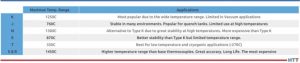
Un termopar base está fabricado de aleaciones básicas como hierro, cromo, níquel, cobre, etc., y constituyen los tipos más comunes en la industria por su versatilidad y costo: los termopares tipo K, E, J, N, y T. Un buen proveedor de sensores te recomendará un termopar de este tipo en función de la aplicación, el rango de temperatura y tu presupuesto (ver Tabla 1).

Tabla 1: Rango de temperatura y uso de los termopares más comunes
Source: GTS México

Por otro lado, un termopar noble está fabricado a partir de metales como platino y rodio: termopares tipo R, S y B. Éstos termopares son más estables a altas temperaturas y mantienen su precisión por mayor tiempo; sin embargo, tienen un costo elevado debido a que se fabrican a partir de metales preciosos. Debido a esta naturaleza, los termopares nobles son la elección preferida para aplicaciones de tratamiento térmico al vacío y procesos de alta temperatura.

2.2 Termopares desechables o no desechables

El segundo criterio de las normativas lo constituye el material con el que se protegen los elementos del termopar.

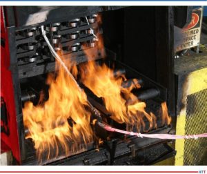
Los termopares desechables son aquellos cuyos elementos están revestidos por materiales como fibra de vidrio, tejido cerámico o recubrimiento polimérico y generalmente se suministran en forma de carrete o bobina. Esta presentación permite al usuario cortar el cable a la medida y fabricar el termopar al unir los dos alambres de un extremo por torsión o soldadura, lo que los hace ideales por ejemplo para aplicaciones de un solo uso como una prueba TUS o termopares de carga (ver Figura 1).

Figura 1: TUS usando termopar desechable tipo K aislado en fibra cerámica
Source: Trucal, Inc.

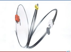
En contraste un termopar no desechable normalmente está protegido con aislamiento cerámico o mineral y revestido en su exterior por una carcasa metálica (los elementos no están expuestos en esta configuración), lo que le proporciona un mayor tiempo de vida útil y por eso se prefieren para emplearse como termopares de control o registro (ver Figura 2).

Figura 2: Termopares no desechables tipo N y K de aislamiento mineral
Source: GTS México

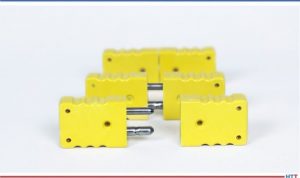
Cualquiera que sea la aplicación, cuando se requiere realizar interconexiones de cableado para la instalación del sensor, dichas conexiones se deben realizar usando conectores y terminales estándar como las que se muestran en la Figura 3, ya que tanto AMS2750 como CQI- 9 prohíben el empalme del cableado.

Figura 3: Conectores estándar tipo K
Source: GTS México

3. Calibración

De acuerdo con la normatividad, todos los termopares usados en operaciones de procesamiento térmico deben haber sido calibrados antes de usarse por primera vez. Para ello, el usuario del termopar debe asegurarse de contar con calibraciones trazables al laboratorio nacional como lo es el NIST en Estados Unidos o su equivalente en México (CENAM).

Las normas de pirometría defi nen los rangos aceptables de error para los termopares en función de su aplicación fi nal: 1) termopares patrón, 2) termopares de prueba (SAT y TUS), 3) termopares de control y registro y 4) termopares de carga. La Tabla 2 describe los máximos errores permitidos a elegir dependiendo del uso del sensor.

Tabla 2: Precisión requerida para sensores de temperatura según AMS2750 y CQI-9
Source: GTS México

Una vez instalado el termopar, el responsable de la operación de tratamiento térmico tiene que deberá documentar la fecha en la que éste entra en servicio, ya que la norma establece un tiempo de vida útil de un sensor en función de la aplicación del mismo.

Al recibir el reporte/certifi cado del termopar, el usuario debe revisar el contenido del documento, pues las normas también definen de manera específi ca la información mínima que debe aparecer en un informe de calibración, que incluye pero no se limita a:

1. Lecturas de prueba
2. Lecturas observadas
3. Factores de corrección
4. Fuente de los datos
5. Acreditación del laboratorio
6. Método de calibración empleado

El certifi cado de calibración puede amparar termopares individuales o un grupo de termopares fabricados a partir del mismo lote (carrete).

Es muy importante observar que tanto AMS2750 como CQI-9 requieren que todas las calibraciones sean realizadas por organismos acreditados en la norma ISO/IEC 17025, por lo que siempre recomiendo que revises el certifi cado de acreditación antes de seleccionar a tu proveedor.

4. En Resumen

Si alguna vez has comprado el termopar equivocado, se lo molesto que puede resultar. Por lo tanto aquí te comparto un resumen para seleccionar el sensor adecuado para su aplicación en 5 sencillos pasos:

1. Define el tipo de termopar: base ( K, T, J, E , N, y M) o noble (S, R, y B)
2. Define el tipo de aislamiento que requieres: fibra textil, polímero, cerámico, metálico, etc.
3. Especifi ca el rango exacto de temperatura en el que operará el sensor
4. Especifi ca el uso del sensor: termopar patrón (estándar), termopar para SAT/TUS, termopar de control / carga
5. Solicita el certifi cado de calibración conforme a la normativa aplicable (AMS2750 o CQI-9)


Referencias

ASTM International. ASTM E230, Standard Specification for Temperature-Electromotive Force (emf) Tables for Standardized Thermocouples, Rev. 2017.

Automotive Industry Action Group. CQI-9 Special Process: Heat Treat System Assessment, 4th Edition. June 2020

International Organization for Standardization. ISO/IEC 17025, General Requirements for the Competence of Testing and Calibration Laboratories, 3rd Edition. 2017.

Nadcap AC7102/8 Audit Criteria for Pyrometry, Rev. A, 2021

SAE Aerospace. Aerospace Material Specifi cation AMS2750: Pyrometry, Rev. G, 2022.


Sobre el autor: Víctor Zacarías es ingeniero metalúrgico egresado de la Universidad Autónoma de Querétaro con estudios en Gerencia Estratégica por parte del Tec de Monterrey. Con más de 15 años de experiencia en la gestión de tratamientos térmicos, actualmente es director general de Global Thermal Solutions México. Víctor ha realizado numerosos cursos, talleres y evaluaciones en México, Estados Unidos, Brasil, Argentina y Costa Rica y ha participado en el Grupo de Trabajo de Tratamiento Térmico de AIAG (CQI-9) y en el Comité de Ingeniería de Materiales Aeroespaciales de SAE.

Contact/Contacto Victor: victor@globalthermalsolutions.com


Find heat treating products and services when you search on Heat Treat Buyers Guide.com


¿Cómo elegir el termopar correcto en Tratamientos Térmicos? Read More »

How To Choose the Right Thermocouple in Heat Treatment

OC

Thermocouples: You can’t accurately heat treat without them. But how can you choose the best one for your needs? What do current regulations require? Read this helpful explanation, by Víctor Zacarías, managing director of Global Thermal Solutions Mexico, to find out how to choose the right thermocouple.

Keywords: Thermocouple, Heat Treatment, Pyrometry, Temperature Measurement and Control, AMS2750, CQI-9

Read the English version of the article below, or find the Spanish translation when you click the flag above right!

This Technical Tuesday article, first published in English and Spanish translations, is found in Heat Treat Today's February's Air & Atmosphere Furnace Systems print edition.

If you have any facts of your own about thermocouples, our editors would be interested in sharing them online at www.heattreattoday.com. Email Bethany Leone at bethany@heattreattoday.com with your own trivia!


Víctor Zacarías
Managing director 
Global Thermal Solutions México

The SAE AMS2750 aerospace standard and the AIAG CQI-9, CQI-11, CQI-12, and CQI-29 automotive assessments are the universally accepted standards for temperature control in thermal processing operations. Among many things, they describe the requirements for the use and control of thermocouples used in process ovens and furnaces. In this article you will find the requirements of these regulations so that you can make a correct decision when choosing a thermocouple, and thus have a repeatable measurement that ensures a reliable process.

1. Application

Contact us with your Reader Feedback!

For the appropriate selection of a thermocouple for the control and/or recording of temperature, you must first take into account the type of process. In choosing the right thermocouple, consider some factors that could alter its performance, such as:

  • The temperature range at which it will be in use
  • The type of atmosphere to which it will be exposed
  • Possible electrical interference
  • The accuracy required by the applicable specification, etc.

Based on the above, existing regulations refer to a specific classification for thermocouples based on their manufacture and final application. These classifications are:
a) Base thermocouples and noble thermocouples
b) Expendable and non-expendable thermocouples

2. Types of Thermocouples and Their Insulation

2.1 Base Thermocouple or Noble Thermocouple

A base thermocouple is made of basic alloys such as iron, chrome, nickel, copper, etc., and they are the most common types in the industry due to their versatility and cost. Base thermocouples are types K, E, J, N, and T. A good supplier of sensors will recommend a thermocouple based on the application, the temperature range, and your budget (see Table 1).


Table 1: Temperature range and application of most common thermocouples
Source: GTS México

On the other hand, a noble thermocouple is made from metals such as platinum and rhodium: types R, S, and B thermocouples. These thermocouples are more stable at high temperatures and maintain their accuracy for a longer time. However, they have the highest cost since they are made from precious metals. Due to this nature, noble thermocouples are the preferred choice for vacuum heat treatment applications and high temperature processes.

2.2 Expendable or Non-expendable Thermocouples

The second criteria from the regulations are the material which protects the elements of the thermocouple.

Expendable thermocouples are those whose elements are covered by materials such as fiberglass, ceramic fabric, or polymeric coating and are generally provided in the form of a spool. This form allows the user to cut the cable to size and manufacture the thermocouple by joining the two wires by twisting or welding, making them ideal for single use applications such as a TUS test or charging thermocouples, for example (see Figure 1).

Figure 1: TUS using type K expendable thermocouple insulated in ceramic fiber
Source: Trucal, Inc.

In contrast, a nonexpendable thermocouple is normally protected with ceramic or mineral insulation and covered on the outside by a metallic sheath (the elements are not exposed in this configuration), which gives it a longer useful life. Therefore, it is preferred for use as a control or recording thermocouple (see Figure 2).

Figure 2: Non-expendable type N and K mineral insulated thermocouples
Source: GTS México

Whatever the application, when wiring interconnections are required for sensor installation, these connections must be made using standard connectors and terminals such as those shown in Figure 3, as both AMS2750 and CQI-9 prohibit the wiring splice.

Figure 3: Standard type K connectors
Source: GTS México

3. Calibration

According to regulations, all thermocouples used in the heat treatment operation must have been calibrated before being used for the first time. The user of the thermocouple must ensure that they have calibrations traceable to a national laboratory such as the NIST in the United States or its equivalent in Mexico (CENAM).

Pyrometry standards defi ne the acceptable error ranges for thermocouples depending on their final application. These categories for final application include: standard thermocouples, test thermocouples (SAT and TUS), control and recording thermocouples, and load thermocouples (see Table 2). Table 2 describes the maximum errors allowed to be selected depending on the use of the sensor.

Table 2: Accuracy required for temperature sensors according to AMS2750 and CQI-9
Source: GTS México

Once the thermocouple is installed, the person responsible for the heat treatment operation must document the date on which it comes into service, since the regulations establish the life of a sensor based on its application.

When receiving the report/certificate of the thermocouple, the user must review the content of the document, since the standards specifically define the minimum information that shall appear in a calibration report, which includes but is not limited to:

1. Test readings
2. Actual readings
3. Correction factors
4. Data source
5. Laboratory accreditation
6. Calibration method used

The calibration certificate can cover individual thermocouples or a group of thermocouples manufactured from the same lot (spool).

It is very important to note that both AMS2750 and CQI-9 require all calibrations to be conducted by ISO/IEC 17025 accredited organizations, so ensure that you review the accreditation certificate before selecting your supplier.

4. In Summary

If you’ve ever bought the wrong thermocouple, you know how annoying it can be. Therefore, here is a quick guide to select the right sensor for your application in five easy steps:

1. Define the type of thermocouple: base (K, T, J, E, N, and M) or noble (S, R, and B)
2. Define the type of insulation you require: textile fiber, polymer, ceramic, metallic, etc.
3. Specify the exact temperature range in which the sensor will operate
4. Specify the use of the sensor: standard thermocouple, SAT/TUS thermocouple, control/load thermocouple
5. Request the calibration certificate in accordance with the applicable regulations (AMS2750 or CQI-9)


References

ASTM International. ASTM E230, Standard Specification for Temperature-Electromotive Force (emf) Tables for Standardized Thermocouples, Rev. 2017.

Automotive Industry Action Group. CQI-9 Special Process: Heat Treat System Assessment, 4th Edition. June 2020.

International Organization for Standardization. ISO/IEC 17025, General Requirements for the Competence of Testing and Calibration Laboratories, 3rd Edition. 2017.

Nadcap AC7102/8 Audit Criteria for Pyrometry, Rev. A, 2021

SAE Aerospace. Aerospace Material Specifi cation AMS2750: Pyrometry, Rev. G, 2022.


About the Author: Víctor Zacarías is a metallurgical engineer from the University of Queretaro with studies in Strategic Management from Tec de Monterrey. With over 15 years of experience in Heat Treatment Management, he is currently the managing director of Global Thermal Solutions México. He has conducted numerous courses, workshops, and assessments in México, the United States, Brazil, Argentina, and Costa Rica. He has been a member of the AIAG Heat Treat Work Group (CQI-9 committee) and the SAE Aerospace Materials Engineering Committee.

Contact Víctor at victor@globalthermalsolutions.com


Find heat treating products and services when you search on Heat Treat Buyers Guide.com


How To Choose the Right Thermocouple in Heat Treatment Read More »

Tempering or Annealing, Which Heat Treatment Works for You?

OCWhat process holds a soft spot in your heart? Tempering or annealing? For Valentine's Day, turn up the heat -- errr heat treatments -- with this look at the differences in tempering and annealing! Heat Treat Today has resources for you to spark some thought and learning on these processes.

Sentiments and strong feelings can certainly be heightened this Valentine's Day. While tempering and annealing may not lend themselves easily to the holiday, we hope you enjoy a bit of a nod to the day in our headings below. Make use of the Reader Feedback button, too, and keep us in the loop with questions and comments on what heat treatment you love.


Problem with Annealing? Get to the Heart of the Issue

An automotive parts manufacturer was running into problems with cracking parts. The variable valve timing plates were returning from heat treatment with this problem. To determine why those parts were cracking after the annealing process, an investigation was launched by metallurgists at Paulo.

The presence of nitrogen combining with the aluminum already present in the particular steel being used was forming aluminum nitrides. What could be done? Read more in the case study article below to find out a workable solution that allowed the annealing to create a crack-free product.

"Part Failure Investigation & Resolution, a Case Study"

Induction, Rapid Air, Oven and Furnace Tempering: Which One do You Love?

Contact us with your Reader Feedback!

This article gives some perspectives, from experts in the field, on what kinds of tempering are available and for what the processes are used.

Hear from Bill Stuehr of Induction ToolingMike Zaharof of Inductoheat, and Mike Grande of Wisconsin Oven with some basics and background information on tempering. Those reasons alone make this resource helpful with information like this: "tempering at higher temperatures results in lower hardness and increased ductility," says Mike Grande, vice president of sales at Wisconsin Oven. "Tempering at lower temperatures provides a harder steel that is less ductile."

More specific in-depth study is presented as well. The Larson-Miller equation is considered, and the importance of temperature uniformity is emphasized. Read more of the perspectives: "Tempering: 4 Perspectives — Which makes sense for you?"

Cast or Wrought Radiant Tubes in Annealing Furnaces - is Cheaper Really What to Fall For?

Marc Glasser, director of Metallurgical Services at Rolled Alloys, takes a look at radiant tubes. He particularly discusses the cast tubes and wrought tubes. For use in continuous annealing furnaces, there are several factors contributing to choice of radiant tube type.

Marc says, "Justification for the higher cost wrought alloy needs to take into consideration initial fabricated tube cost, actual tube life, AND the lost production of each anticipated downtime cycle as these downtime costs are often much more than material costs." He probes into areas that may not be considered when thinking of all the costs involved. Read more of his article "Radiant Tubes: Exploring Your Options."

Tempering Furnaces: Improvements are Thrilling

The expert behind this piece shows the importance of tempering, particularly in automotive fastener production. Tim Donofrio, vice president of sales at CAN-ENG Furnaces International Limited examines what's working in the tempering furnaces. The products are meeting and exceeding expectations.

Highly efficient, continuous soft handling mesh belt heat treatment systems are getting the job done. Read more about the advances in tempering furnaces by clicking here: "Mesh Belt Heat Treatment System Advancements for Automotive Fastener Production."

Additional Resource To Catch Your Eye

To wrap up this Technical Tuesday post on tempering and annealing, head over to this additional resource to round out the scope of each process. "What is the Difference: Tempering VS. Annealing" gives a summary perspective on the heat treatments discussed above.


Find heat treating products and services when you search on Heat Treat Buyers Guide.com


Tempering or Annealing, Which Heat Treatment Works for You? Read More »

Radiant Tubes: Exploring Your Options

OC There are many radiant tube options on the market, so which one is best for your furnace and your budget? In this column that compares radiant tubes in carburizing and continuous annealing furnaces, discover how two major types of radiant tubes stack up.

Marc Glasser, director of Metallurgical Services at Rolled Alloys, investigates more deeply the two choices. This Technical Tuesday discussion on radiant tubes options will be published in Heat Treat Today's February 2023 Air & Atmosphere Heat Treating Systems digital edition.


Introduction

Marc Glasser
Director of Metallurgical Services
Rolled Alloys
Source: Rolled Alloys

Radiant tubes are used in many types of heat treating furnaces from carburizing furnaces to continuous annealing of steel strip. Generally, a heat treater has three options for radiant tubes: cast tubes, wrought tubes, and ceramic silicon carbide tubes. Silicon carbide tubes are rarely used by heat treaters, so this article will not delve too deeply into this option. Suffice it to say, ceramic materials can often handle much higher temperatures at the expense of ductility; ceramics are more brittle than metals, making them prone to failure from the small impacts, so metal cages are sometimes fabricated to protect them. Most of the tubes being used today are cast radiant tubes. With new casting technology — primarily centrifugal casting — thinner tubes are being cast at a lower cost, which then results in a shorter life.

The primary factors for choosing radiant tube material are tube temperature and carbon potential of the furnace atmosphere. Cost-benefit analysis should also be considered. There are multiple applications for radiant tubes, including carburizing furnaces, continuous annealing furnaces for steel sheet galvanizing, steel reheat furnaces, and aluminum heat treating. This article will explore two of the aforementioned radiant tube options, specifically for carburizing and continuous annealing furnaces.

Radiant Tubes for Carburizing Furnaces

Gas carburization is traditionally performed between 1650°F and 1700°F at a carbon potential of 0.8% approximating the eutectoid composition. In today’s competitive environment, more heat treaters are increasing temperatures to 1750°F and pushing carbon potentials as high as 1.6% to get faster diffusion of carbon while spending less time at temperature. INCONEL® HX (66% Ni, 17% Cr) has been a common cast alloy seen in carburizing furnaces. This alloy is regularly selected for its resistance to oxidation and carburization up to 2100°F. Super 22H is more heavily alloyed than HX and is seeing more use as carbon potentials increase but at a premium price. With advances in centrifugal castings, cast tube wall thicknesses have decreased from 3/8-inch to 1/4-inch. Some heat treaters have shared that this decrease in wall thickness has also led to shorter tube life.

Fabricated and welded radiant tubes in alloys 601 and RA 602 CA® have been tested in industry. When tested, these wrought alloys were fabricated to have a wall thickness of 1/8-inch. At the extremes, tubes fabricated from 601 only lasted 50% as long as cast HX. Historically, HX tubes have been approximately 33% higher in cost than that of 601 and utilize heavier 3/8-inch walls. A little-known fact is that by switching to a thinner wall cast tube, the life drops by 50%. By switching to 1/8-inch wall thickness, RA 602 CA tube life has been extended to eight years or more, while running at 1750°F and up to 1.6% carbon potential, at just a 33% premium over cast HX. Life cycle data are presented in Figure 1.

Figure 1. These life cycle comparisons were done in carburizing furnaces only. In non-carburizing furnaces, justification of alloy selection is dependent on actual operating conditions and each individual operator’s own experience.
Source: Rolled Alloys

Radiant Tubes for Continuous Annealing Furnaces

In the area of continuous annealing, the cast alloy of choice is HP/HT (35% Ni, 17% Cr, 1.7% Si, 0.5% C). Here again, this casting has been compared to 601 and RA 602 CA, with the same results. The total life data from these trials are also incorporated into Figure 1. During the collection of this data, there has been no effort to measure the actual tube temperature, so the effect of tube temperature is not clearly defined. In these continuous annealing furnaces, it has been reported that the tubes at the entry end are subject to more heat absorption as burners are firing more due to the continuous introduction of cold material; in trials, the operators have not kept adequate documentation of specific tubes, making justification more diffcult.

Justification for the higher cost wrought alloy needs to take into consideration initial fabricated tube cost, actual tube life, AND the lost production of each anticipated downtime cycle as these downtime costs are often much more than material costs. Only individual fabricators can determine these costs.

The Economics

Table 1
Source: Rolled Alloys

Table 1 above shows the economics of metal alloy choice. To properly interpret, understand that the costs are not actual, but rather relative to 601, so a round number of 1000 was used. With a 30% greater cost of cast tubes, that translates to a relative cost of $1300. The annual cost is the amortized cost over the life of the tube. The total eight-year cost is the relative cost times the number of tubes that would have to be purchased to obtain the life cycle of one tube of the longest-lasting material over its full life cycle.

Missing in this analysis is the additional cost of downtime and lost production. For the replacement of radiant tubes in a carburizing furnace, this typically entails a full week to turn a furnace off, allow it to cool, replace the tubes, and then heat it up again. Many heat treaters do not consider this, and therefore it is a hidden cost. Even without the downtime being considered, by examining the total cost of materials (including replacements) compared to the longest-lasting tube, it turns out that the most expensive tube is the cheapest tube. The obstacle to overcome is whether the heat treater is willing to wait eight years to realize these cost savings.

There can be additional factors to consider. With improvements in the efficiency of casting, the actual costs of the thinner wall casting may be somewhat less, but to match the overall cost of the longest-life material, it would have to be less than half the expected cost. As better, more expensive cast alloys become accepted and actual life data becomes available, these more costly alloys can be added to this table for comparative analysis, too.

This same method of analysis can be applied to radiant tubes for continuous annealing furnaces, but more details will need to be added including furnace position. Different alloy candidates will have to be put to the test in actual operations, carefully document what alloy is in what position or location, and when it gets changed out. This becomes quite cumbersome when annealing furnaces (depending on design and manufacture) can have over 200 radiant tubes.

Conclusion

Currently, cast alloy tubes dominate the market. The concept of total life cycle cost has been introduced as a means of more accurately justifying one’s choice of radiant tube. This comes into play more as processes are pushed beyond traditional process conditions. Cost-benefit analysis must be balanced over acceptable amortization time, of course. However, performing the full analysis as well as the costs saved from downtime may lead some heat treaters to some alternate materials.

About the author: Marc Glasser is the director of Metallurgical Services at Rolled Alloys and is an expert in process metallurgy, heat treatment, materials of construction, and materials science and testing. Marc received his bachelor’s degree in materials engineering from Rensselaer Polytechnic Institute and a master’s degree in material science from Polytechnic University, now known as the NYU School of Engineering. Contact Marc at mglasser@rolledalloys.com


Find heat treating products and services when you search on Heat Treat Buyers Guide.com


Radiant Tubes: Exploring Your Options Read More »