Vacuum heat treat operations expand for ZDT Glimag, an entity providing services in the field of vacuum heat treatment, laboratory tests, and production of parts for mining machines.
The addition of this Vector® vacuum furnace will be the third vacuum furnace from SECO/WARWICK. The current design has an operating space of 600 x 600 x 900 mm and will be equipped with numerous options to allow a wide range of heat treatment processes for various steel grades. Main processes will include vacuum brazing, FineCarb® vacuum carburizing, and high-pressure hardening. The design of the chamber size will enable efficient heat treatment of large packages of test and research elements.
The efficiency of processes is also influenced by the ability to cool at 15 bar (which, unlike the old furnaces, eliminates the need to wash the parts after the process). In combination with inverter control, the system also helps reduce power consumption peaks, which are so problematic today. Another big advantage is low heat losses and appropriate temperature uniformity in the heating chamber, which is resistant to rapid wear and is easy to use and service.
Beata Kowalewska President of the Management Board – Financial Director of ZDT Glimag Source: LinkedIn
Beata Kowalewska, president of the Management Board – Financial Director of ZDT Glimag, comments: “Since the 1960s, we have been designing prototypes, conducting research and technological tests, and implementing new technologies for mining. We are currently in the process of materializing the project titled ‘Implementation of an innovative product resulting from research and development work: a brake pad with a composite friction layer with increased abrasion resistance,’ implemented under the European Funds for a Modern Economy (FENG) 2021-2027 Program. FENG is a program supporting entrepreneurs in the area of broadly understood innovation. It places great emphasis on R&D activities.”
He continues, “The new SECO/WARWICK furnace fits perfectly into the policy of broadly understood modernity implemented in this project. It will streamline and expand the scope of heat treatment processes and improve their economics, taking into account energy savings and the graphite chamber efficiency. It will also ensure the process cleanliness and velocity. With the FineCarb® vacuum carburizing option, the technology also increases our flexibility and research capabilities. Additionally, this technology will allow us to perform more difficult processes requiring extremely low contamination levels, thanks to the ability to obtain the appropriate vacuum needed for these processes.”
Maciej Korecki VP of the Vacuum Furnace Segment SECO/WARWICK Source: SECO/WARWICK
Maciej Korecki, VP of the Vacuum Furnace Segment in the SECO/WARWICK Group, comments on ZDT Glimag saying, “It is a center very well oriented in the metal heat treatment industry, constantly testing new, innovative solutions that in turn make the mining industry more efficient. The new Vector will introduce revolutionary changes in the hardening plant, introducing innovation and a very wide range of precise processes.”
The Vector® line vacuum furnaces can be used in most standard vacuum carburizing, hardening, tempering, annealing, supersaturation, and brazing processes. At the same time, the solution can be adapted to the recipient’s individual requirements, and therefore to a specific industry, an attribute necessary for research centers that test innovative solutions for external customers.
The solution‘s characteristic features are convection heating, i.e., a system improving the heat transfer efficiency when heating at lower temperatures, and directional cooling, which allows complex, flimsy, and long elements to be cooled in various ways, minimizing their deformations. An additional advantage is the vacuum carburizing option, which allows users to carry out precise processes to increase the steel surface hardness (carburizing) during the entire thermal process.
The original press release from SECO/WARWICK Group is available here.
Aalberts surface technologies, a global provider of specialized thermal processing, surface treatment, and material coating solutions, announced on Wednesday, February 14, 2024, that it is making changes to its U.S. portfolio in response to changing market dynamics. The provider has made investments in its Canton, OH, facility, adding austempering capabilities which will provide a logistically favorable option to clients located in the Midwestern, Eastern, and Northeastern U.S. markets. To balance the capacity available in the market with demand, the heat treat provider will be closing its plant in Ft Smith, AR.
Steve Wyatt President Aalberts surface technologies – HIP | Braze | Heat Treatment
Source: Aalberts Surface Technologies
“The decision to exit the austempering market in the South was a difficult one, but the market for austempering in the addressable market for our Ft Smith, AR plant simply is not sufficient to sustain the operation. We recognize the hardships that this difficult decision may create and will be working with our Ft Smith Team to minimize the impact as much as possible, including exploring opportunities at one of the many other Aalberts locations,” says Steve Wyatt, president of Aalberts surface technologies – HIP | braze | heat treatment.
The austempering capabilities in Canton, OH, will startup in mid-February 2024 and be fully production ready by the end of March 2024. The decommissioning of the Ft Smith, AR, plant will begin in mid-February 2024, with production expected to cease when we have completed working with clients to transition their product, but not later than April 2024.
Oliver Jaeger CEO Aalberts surface technologies LinkedIn
“We are focused on optimizing our portfolio around the globe; this initiative is about responding to what the market needs and where it is needed. In our business, logistics is a significant percentage of the total cost of our services, therefore, we must constantly be seeking ways to minimize that cost for our customers. We are committed to growing in the U.S. and look forward to partnering with our customers to develop solutions that contribute to our mutual success,” says Oliver Jaeger, CEO of Aalberts surface technologies.
The original press release from Aalberts surface technologies is available upon request.
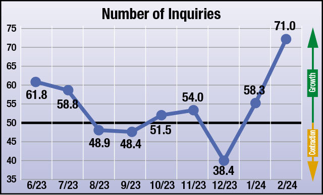
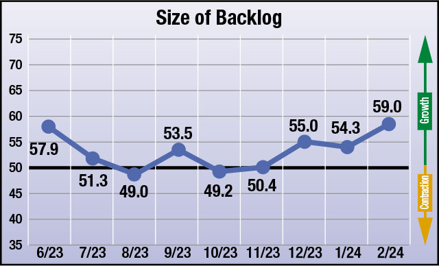
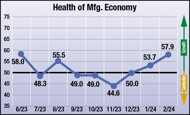
The four heat treat industry-specific economic indicators gathered by Heat Treat Today each month since June 2023 reflect the highest expectations for economic growth that we’ve seen. For this month of February, suppliers to the industry have particularly high expectations for one indicator.
The numbers, which were compiled in the second week of February, show that responding parties strongly anticipate inquiry levels and value of bookings to grow; it will be interesting to see if expectations for number of inquiries will increase at the same rate in future months. Industry suppliers are also expecting backlogs and overall health of the manufacturing economy to be up this month.
The results from this month’s survey (February) are as follows; numbers above 50 indicate growth, numbers below 50 indicate contraction, and the number 50 indicates no change:
Anticipated change in the Number of Inquiries from January to February: 71.0
Anticipated change in Value of Bookings from January to February:65.5
Anticipated change in Backlog Size from January to February: 59.0
Anticipated change in the Health of the Manufacturing Economy from January to February: 57.9
Data for February 2024
The four index numbers are reported monthly by Heat Treat Today and made available on the website.
Heat TreatToday’sEconomic Indicatorsmeasure and report on four, heat treat industry indices. Each month, approximately 800 individuals who classify themselves as suppliers to the North American heat treat industry receive the survey. Above are the results. Data started being collected in June 2023. If you would like to participate in the monthly survey, please click here to subscribe.
Find heat treating products and services when you search on Heat Treat Buyers Guide.com
Automating Brinell hardness testing could mean saving on expensive laboratories, as was the case for one oil tool industry manufacturer. Learn the basics of Brinell hardness testing, its strengths and weaknesses, and options for automation.
This Technical Tuesday article, written by Alex Austin, managing director of Foundrax Engineering Products Ltd., was originally published in Heat Treat Today’sDecember 2023 Medical and Energy Heat Treat print edition, both in English and in Spanish.
Brinell Hardness Testing: Strengths and Weaknesses
Alex Austin, Managing Director, Foundrax Engineering Products Ltd.
In many steelworks producing large forgings and billets, in numerous heat treatment companies, and near many factory lines producing components for safety-critical applications, you’ll find a Brinell hardness tester. These machines have been used all over the world for more than a century (the test was first demonstrated by its inventor, the Swedish metallurgist August Brinell, in 1900), determining metal hardness by means of a tungsten carbide indenter ball that leaves a dish-shaped indentation in the surface of the test material.
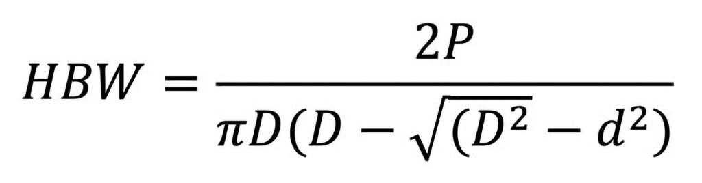
In the test, the material sample is placed on a rigid anvil, and the indenter descends onto it under loads ranging from 1 kg up to 3,000 kg, depending on the material. Indenters vary in diameter from 1 mm to 10 mm. Most tests use a 3,000 kg load and a 10 mm ball, and the standards always refer to this as “HBW 10/3000.” HBW stands for Hardness Brinell Wolfram, Wolfram being another name for the tungsten carbide the indenter ball is made from. After the (approximately) fifteen second indenting cycle, the indentation is measured across both its x and y axes, as a minimum, by a special calibrated microscope. The mean of the diameter readings is then fed into the Brinell equation.
Contact us with your Reader Feedback!
Naturally, most technicians would rather not use that equation, so they look the indentation diameter up on a chart and “read across” to the derived hardness.
The great advantage of the Brinell test, when considered alongside other metal hardness testing methods, is that the large indentation diameter (typically between 2.4 mm and 6 mm) means the test result is generally unaffected by the grain structure of the metal. It also means that the surface of the test sample can be adequately prepared in just a few seconds with an angle grinder. For these reasons, the test is regarded by many as the “default” one for rough-surfaced and/or coarse-grained samples.
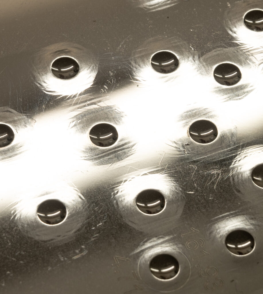
On the block in image (Figure 4), the distortion around the indentations can be seen very clearly.
That seems pretty simple, but there are inherent weaknesses in the Brinell test: measuring the indentation. In our previous article (read it in Heat Treat Today’s August 2023 Automotive Heat Treat print edition), we used this image (Figure 2) to illustrate how difficult it could be to work out exactly where an indentation edge begins and ends.
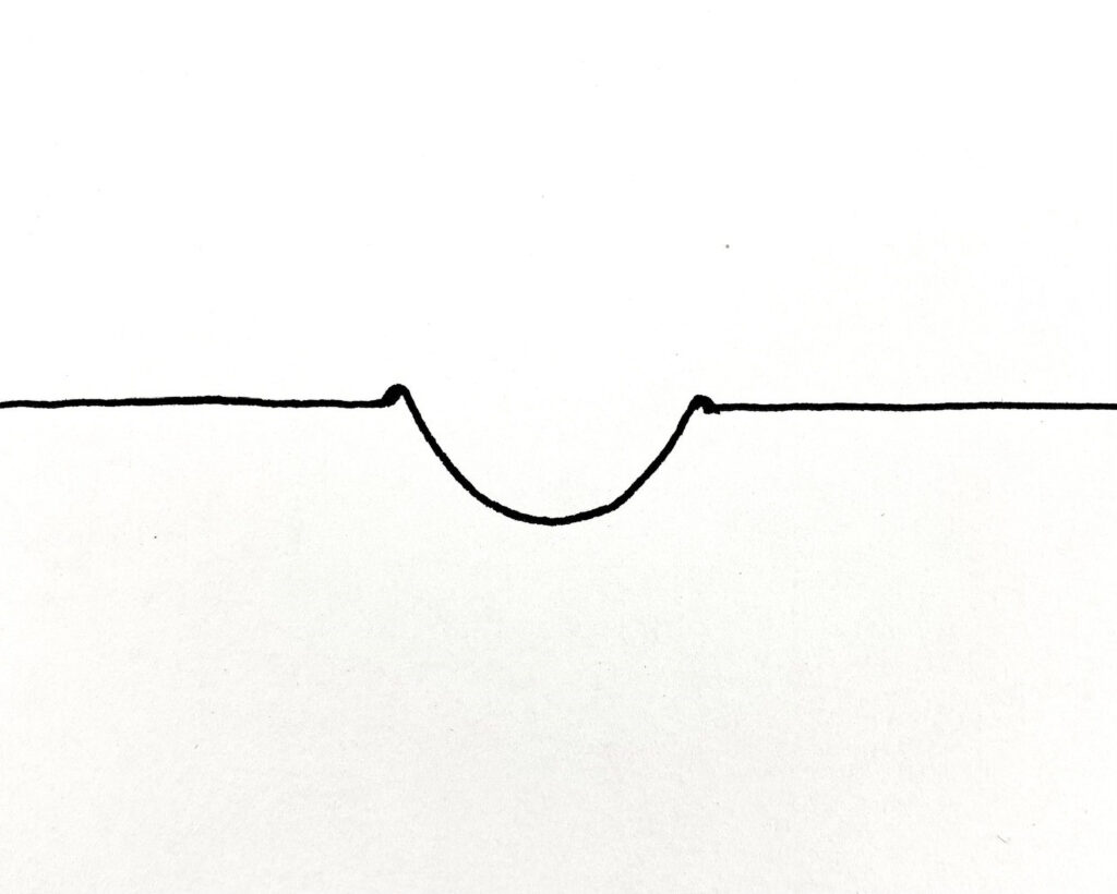
You might look at Figure 2 and think, “I’m pretty confident about where that indentation edge is,” but it’s trickier than it looks, because the process of indenting doesn’t just push material downwards; it also spreads it sideways, and you get a “pile up” around the rim of the indentation. The pile up may be difficult to see on hard material, or there may be a subtle “lip” inside the pile up that represents the true edge, but considered in cross-section, indentations look roughly like this simple sketch above (Figure 3).
Figure 2. Measurement of Brinell hardness test indentation (Source: Foundrax Engineering Products Ltd.)Figure 3. Sketch of cross-section of indentation (Source: Foundrax Engineering Products Ltd.)
The overhead light illuminates the “pile up” rim very clearly on some of those indentations as a highlight around the edge. Where, exactly, does the pile up end and the true edge of the indentation begin? Bear in mind that 0.2 mm can equal 20 hardness points. You could show an indentation to three experienced workshop technicians and receive three different answers to the diameter question, and this problem has been a challenge of the Brinell test from its inception. Special blocks are available for training technicians in measurement, but the problem of operator interpretation was such that, in some quarters, the Brinell test was regarded as a bit “rough and ready.” “Ok for the workshop but not for the lab,” was perhaps how it was once seen.
Why Automate the Brinell?
The first question to consider when looking at the automation of the Brinell test is the measurement system because this is the inherent weakness. There are, of course, applications where only narrow tolerances are acceptable, and disagreements can arise between customers and suppliers.
Over the years, certain manufacturers, who mill heat treated materials for the oil tool industry, confided to us that they were regularly using expensive testing laboratories because of clients disputing the hardness figures of their products. They had previously been using manual microscopes. Obviously, this has reputational, as well as financial, consequences. If a manual microscope is employed on raw materials at the goods-in-process stage and there’s an error reading the hardness, you could find at final machining that you have put a lot of time and effort into a part that, in the end, is too hard or soft for the intended application.
Manually manipulating the microscope may not be worth the effort, especially when even a diligent operator may read the result incorrectly. With an automatic Brinell microscope, however, there is the possibility of major time and cost savings.
4 Levels of Automation
#1 Beginnings of Brinell Automation
The first step in automating Brinell hardness testing began 40 years ago when the world’s first automatic measurement microscope hit the market. The system, still being regularly refined, was able to measure the diameter of the indentation across over 100 axes, calculate the mean, and determine the hardness in a split second. It can handle most surface irregularity, operate in poor lighting, and warns operators of unacceptable surface preparation. Additionally, its precision adjusts for spatial error when lining up with a graticule. Within a few years of launch, a major oil tool manufacturer’s quality chief recommended its use to his suppliers, and user uptake was rapid.
#2 Integrated Microscope Model
A further step in automation is to dispense with operator handling of the microscope entirely by the acquisition of a tester with an integrated microscope. The microscope mentioned above, for example, is a feature on several hardness testing machines. The heavy-duty indenter holder pivots away from its normal line of thrust at the end of the indenting cycle, allowing a supra-mounted camera to view the indentation. This is hugely advantageous: no separate apparatus near the test machine, reduced handling time, and thus, much faster testing overall. Results from such machines are displayed next to the control panel and quickly uploadable to company quality systems.
Figure 4. Block with distortion around indentations (Source: Foundrax Engineering Products Ltd.)
#3 Dispensing of Manual Operations
Another automation option is to dispense with a hand-cranked anvil capstan and purchase a tester with a fixed anvil and movable test head. The technician is not required to manually raise and lower the anvil to allow for variations in the size of sample. Instead, the test head automatically “takes up” the space and also clamps the test piece very securely in place during the test cycle.
#4 Incorporate Custom Hardness Tester in Production Line
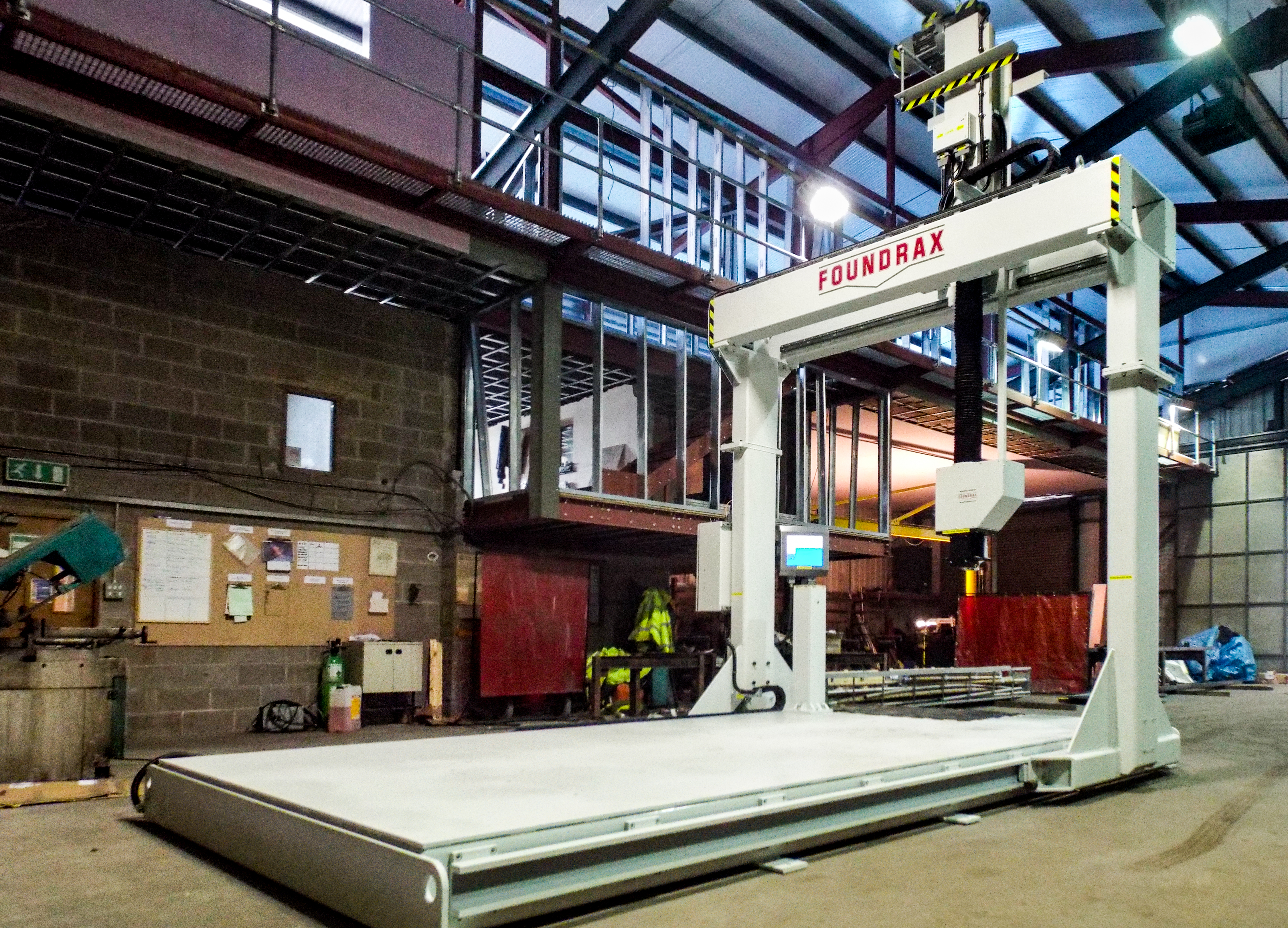
The fourth, and obviously most dramatic, automation step to consider is incorporating a custom-designed hardness tester into the production line. In some industries, this is essential. Large billets and forgings can’t be lifted into the jaws of a benchtop or floor-standing Brinell tester; so, for highly accurate testing of such items, a larger machine is required (Figure 5).
Figure 5. A custom-designed production line hardness tester. This machine is now in Texas. (Source: Foundrax Engineering Products Ltd.)
The whole gantry moves on one axis of travel while the test head moves perpendicular to that and, of course, up and down. This provides the full x, y, z movement. Large samples are maneuvered on and off by crane. The test head assembly incorporates the automatic microscope and results are displayed on a screen beside the control panel. Test results can be instantly uploaded to factory quality systems. The head assembly can also incorporate a milling tool for surface preparation!
With any decision to purchase plant and machinery equipment, some form of cost-benefit analysis is worthwhile. Clearly, if you’re doing a significant amount of business annually with a customer who is threatening to cease contracting with you because your hardness measurements are wrong too often, then the decision to buy an automatic microscope is not a difficult one. If staff are on overtime because mandatory hardness testing is adding too much time to production schedules, then a heavy-duty production machine with automatic microscope, movable test head, and sample clamp will pay for itself easily.
One thing is certain: Every automation option in Brinell testing increases accuracy and saves time.
About the Author
Alex Austin has been the managing director of Foundrax Engineering Products Ltd. since 2002. Foundrax has supplied Brinell hardness testing equipment for 60+ years and is the only company in the world to truly specialize in this field. Alex sits on the ISE/101/05 Indentation Hardness Testing Committee at the British Standards Institution. He has been part of the British delegation to the International Standards Organization advising on the development of the standard ISO 6506 “Metallic materials – Brinell hardness test” and is the chairman and convenor for the current ISO revision of the standard.
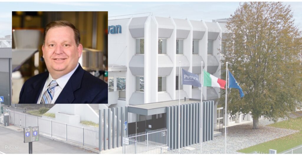
PiovanGroup is launching a new strategic division for industrial and process refrigeration, the result of the integration of the businesses operated by the recently acquired Thermal Care and Aquatech.
With a legacy spanning over half a century, Thermal Care andAquatech have solidified themselves as prominent players in industrial process cooling markets by providing high‐quality, sustainable equipment and solutions. Operating primarily out of the U.S., near Chicago, Thermal Care has been a leader in the design, manufacturing, sales, and service of heat‐transfer solutions across various industries.
Thermal Care and Aquatech products manufactured in North America, Europe, Asia, and South America will continue to be produced and sold in their respective regions, now under the newly established division. The integration of these business units will provide R&D efficiencies and an expanded portfolio of products, solutions, and services capable of serving a wider range of market sectors.
The Thermal Care brand now expands globally, facilitated by the integration of the Aquatech business which moves forward under the banner of Thermal Care. The inclusion of PiovanGroup into the Thermal Care logo not only signifies geographical expansion but also reflects a unified vision for growth and innovation.
The new division, headed by Lee Sobocinski, current president of Thermal Care Inc., shall operate under the Thermal Care brand and will have consolidated sales of approximately 100 million Euro, globally. The creation of the global brand, coupled with the exchange of the institutional knowledge within PiovanGroup into this emerging division, will provide assistance to clients, irrespective of their geographical presence, spanning from preliminary sales engagement to post‐sales support.
The announcement of this pivotal moment in the ongoing progression of Thermal Care coincides with the commemoration of the group’s 90th anniversary and its 60th anniversary in the polymer industry.
The original press release from Thermal Care is available upon request.
Sometimes our editors find items that are not exactly “heat treat” but do deal with interesting developments in one of our key markets: aerospace, automotive, medical, energy, or general manufacturing.
To celebrate getting to the “fringe” of the weekend, Heat Treat Today presents today’s Heat Treat Fringe Friday: an exciting development in metal 3D printing that one might even say is "out of this world."
Rob Postema Technical Officer ESA
Metal 3D printing will soon take place in orbit for the first time. A pioneering European-made metal 3D printer is on its way to the International Space Station on the Cygnus NG-20 resupply mission which launched January 30, 2024.
“This new 3D printer printing metal parts represents a world first, at a time of growing interest in in-space manufacturing,” explains ESA technical officer Rob Postema. “Polymer-based 3D printers have already been launched to, and used aboard the ISS, using plastic material that is heated at the printer’s head, then deposited to build up the desired object, one layer at a time.
“Metal 3D printing represents a greater technical challenge, involving much higher temperatures and metal being melted using a laser. With this, the safety of the crew and the Station itself have to be ensured – while maintenance possibilities are also very limited. If successful though, the strength, conductivity and rigidity of metal would take the potential of in-space 3D printing to new heights.”
Once arrived at the International Space Station, ESA astronaut Andreas Mogensen will prepare and install the approximately 180 kg Metal 3D printer in the European Draw Rack Mark II in ESA’s Columbus module. After installation, the printer will be controlled and monitored from Earth, so the printing can take place without Andreas’s oversight.
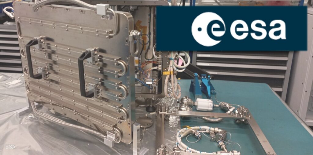
Metal 3D printer in operation on Earth
Source: ESA
The Metal 3D Printer technology demonstrator has been developed by an industrial team led by Airbus Defence and Space SAS – also co-funding the project – under contract to ESA’s Directorate of Human and Robotic Exploration.
“This in-orbit demonstration is the result of close collaboration between ESA and Airbus' small, dynamic team of engineers,” comments Patrick Crescence, project manager at Airbus. “But this is not just a step into the future; it's a leap for innovation in space exploration. It paves the way for manufacturing more complex metallic structures in space. That is a key asset for securing exploration of Moon and Mars.”
The printer will be printing using a type of stainless-steel commonly used in medical implants and water treatment due to its good resistance to corrosion.
The stainless-steel wire is fed into the printing area, which is heated by a high-power laser, about a million times time more powerful than your average laser pointer. As the wire dips into the melt pool, the end of the wire melts and metal is then added to the print.
ESA materials engineer Advenit Makaya from the ESA’s Directorate of Technology, Engineering and Quality, provided technical support to the project: “The melt pool of the print process is very small, in the order of a millimetre across, so that the liquid metal’s surface tension holds it securely in place in weightlessness. Even so, the melting point of stainless steel is about 1400 °C so the printer operates within a fully sealed box, preventing excess heat or fumes from reaching the crew of the Space Station. And before the print process begins the printer’s internal oxygen atmosphere has to be vented to space, replaced by nitrogen – the hot stainless steel would oxidise if it became exposed to the oxygen.”
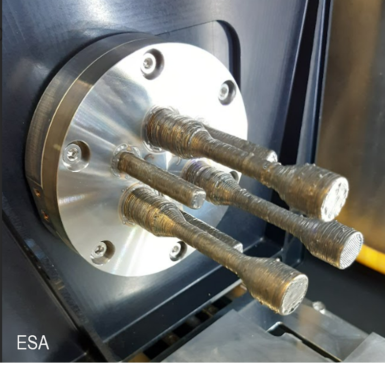
Four interesting shapes have been chosen to test the performance of the Metal 3D printer. These first objects will be compared to the same shapes printed on ground, called reference prints, to see how the space environment affects the printing process. The four prints are all smaller than a soda can in size, weigh less than 250 g per print, and takes about two to four weeks to print. The scheduled print time is limited to four hours daily, due to noise regulations on the Space Station – the printer’s fans and motor of the printer are relatively noisy.
Once a shape has been printed, Andreas will remove it from the printer and pack it for safe travels back to Earth for processing and analysis, to understand the differences in printing quality and performance in space, as opposed to Earth.
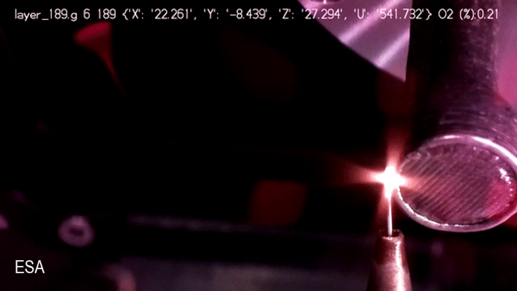
Metal 3D printer test print
Source: ESA
One reference and 0xg print, which is a part of a dedicated tool, will go to the European Astronaut Centre (EAC) in Cologne, Germany. Another two will be headed to the technical heart of ESA, the European Space Research and Technology Centre (ESTEC), where a team at the Materials and Electrical Components Laboratory awaits the samples for macro and micro analysis of the printed parts. The final print will go to the Technical University of Denmark (DTU), who proposed its shape, and will investigate its thermal properties in support of e.g. future antenna alignment.
“As a technology demonstration project, our aim is to prove the potential of metal 3D printing in space,” adds Rob. “We’ve already learned a lot getting to this point and hope to learn a lot more, on the way to making in-space manufacturing and assembly a practical proposition.”
One of ESA’s goals for future development is to create a circular space economy and recycle materials in orbit to allow for a better use of resources. One way would be to repurpose bits from old satellites into new tools or structures. The 3D printer would eliminate the need to send a tool up with a rocket and allow the astronauts to print the needed parts in orbit.
Tommaso Ghidini, head of the mechanical department at ESA, notes: “Metal 3D in space printing is a promising capability to support future exploration activities, but also beyond, to contribute to more sustainable space activities, through in-situ manufacturing, repair and perhaps recycling of space structures, for a wide range of applications. This includes in-orbit large infrastructure manufacturing and assembly as well as planetary long-term human settlement. These aspects are key focuses in ESA's upcoming technology cross-cutting initiatives.”
Thomas Rohr, overseeing ESA's Materials and Processes Section, adds: “This technology demonstration, showcasing the processing of metallic materials in microgravity, paves the way for future endeavours to manufacture infrastructure beyond the confines of Earth.”
This press release from The European Space Agency can be found in its original form here.
Tom Schulz Sales Manager L&L Special Furnace Source: L&L
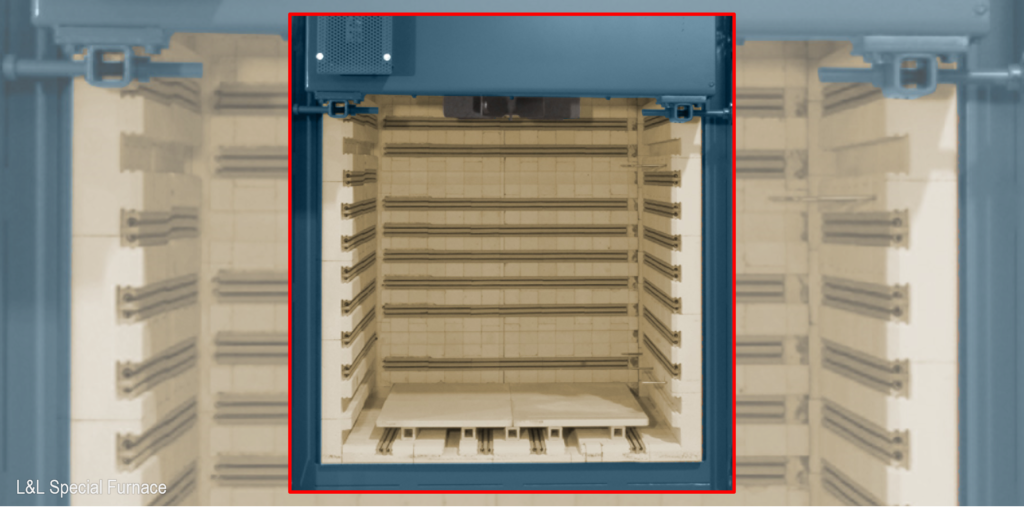
An investment castings manufacturer's heat treat department received a large floor-standing box furnace from a North American specialty furnace company. The furnace will be used as support in the client's tool and die production along with tempering of finished castings.
The L&L model XLE3436 box furnace from L&L Special Furnace has an effective work zone of 34” wide by 22” high by 32” deep. It is equipped with a direct-lift vertical door with a floor switch to activate. The cantilevered vertical door eliminates the need for the upright structure to reduce the overall height of the equipment.
Tom Schulz, sales manager at L&L, highlights the key role this will play for the heat treat department, saying that this type of furnace is the company's “workhorse when it comes to thermal processing.”
The inert blanketing gas enables the part to be heat-treated with minimal surface de-carb. A stack light indicates the furnace status via an audible and visual indicator light mounted on top of the control.
Additionally, the furnace is equipped with a pyrometry package that has reference control thermocouple ports along with corner locations to record the high and low points within the unit as indicated by the latest temperature uniformity survey.
The original press release from L&L Special Furnace is available upon request.
IperionX, a producer of high-quality titanium alloys, has commissioned a titanium production facility in Virginia.
Anastasios (Taso) Arima, CEO of IperionX, commented in a letter to the company’s shareholders: “Our Virginia titanium facility is designed to apply our HAMR [Hydrogen Assisted Metallothermic Reduction] and HSPT [Hydrogen Sintering & Phase Transformation] technologies to produce sustainable, high-quality and high strength titanium metal products at low cost.”
Full capacity is scheduled for 2026, with more than 1,000 metric tons of titanium produced per year. Using titanium powder produced on site, IperionX plans to employ unique forging technologies to produce titanium mill products and near net shape titanium products and to apply AM to produce 3D printed titanium products.
Arima also added, “We engaged with Lockheed Martin, GKN Aerospace, and the U.S. Army to replace traditional titanium mill products, in this case titanium plate, providing a new domestic and sustainable source to enhance their critical supply chains.” To aid these goals, Iperion is installing a large-scale, industrial furnace at their Virginia facility.
This letter to IperionX’s shareholders can be found here.
In Part 1, the author underscored the importance of understanding the changes in gas composition through three steps of its production: first, the production in the combustion chamber; second, the cool down of gas to bring the Exothermic gas (Exo gas) to below the ambient temperature; and third, the introduction of the gas to the heat treat furnace. Read Part 1, published in Heat Treat Today’sAugust 2023Automotive Heat Treat print edition, to understand what Exo gas is and to learn about the composition of gas in the first step.
Harb Nayar
Founder and President TAT Technologies LLC Source: TAT
As the author demonstrated in Part 1, Exo gas composition changes in its chemistry for heat treatment; this first step is how the gas composition changes when it is produced in the combustion chamber. The composition of reaction products, temperature, Exothermic energy released, various ratios, and final dew point are all factors that need to be considered to protect metal parts that will be heat treated in the resulting atmosphere.
Now, we’ll turn to Steps 2 and 3.
Step 2: Composition of Exo Gas after Exiting the Reaction Chamber Being Cooled Down
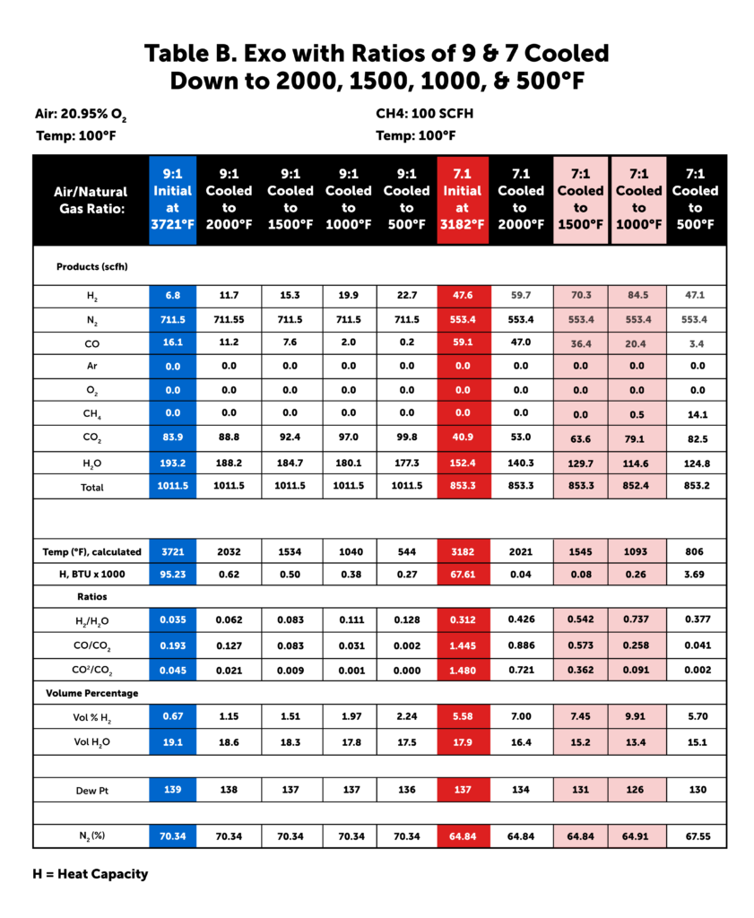
The two examples that follow demonstrate how lean and rich Exo under equilibrium conditions change as they are cooled from peak equilibrium temperature in the combustion chamber down to different lower temperatures (Table B). This cool down brings the Exo down to below ambient temperatures to avoid water condensation.
Example 1: Lean Exo Gas with a 9:1 Air to CH₄ Ratio
The first column highlighted in blue shows the composition of the lean Exo gas as generated in the reaction chamber with an air to natural gas ratio of 9:1. The peak temperature as generated in the combustion chamber is 3721°F. The next four columns show how the composition changes when the lean Exo gas is slowly cooled from 3721°F to 2000°F, 1500°F, 1000°F, and 500°F under equilibrium condition. The following key changes take place as the temperature of the lean Exo is lowered from the peak temperature to 500°F:
Hydrogen volume almost triples from 0.67% to 1.97%.
H₂O volume decreases slightly from 19.1% to 17.5%, but still is very high at all temperatures.
Oxidation-reduction potential (ORP) changes as the H₂ to H₂O ratio increases from 0.035 to 0.111. At all temperatures, it is very low.
CO and the CO to CO₂ ratio drop in a big way, making lean Exo from being decarburizing at higher temperatures to being highly decarburizing at lower temperatures.
The percentage of N₂ remains at 70.34 at all temperatures.
There is no C (carbon, i.e., soot) or residual CH₄ at all temperatures.
For all practical purposes, at an air to natural gas ratio of 9:1, the Exo gas as generated is predominantly an N₂ and H₂ (steam) atmosphere with some CO₂ and small amounts of H₂ and CO.
Table B. Air to Natural Gas at 9:1 and 7:1, cooled to various temperatures
Example 2: Rich Exo Gas with a 7:1 Air to CH₄
The column under ratio of seven is highlighted as red to show the composition of the rich Exo gas as generated in the reaction chamber with an air to CH₄ ratio of seven. The peak temperature is 3182°F — significantly lower than that for lean Exo. The next four columns show how the composition changes when the rich Exo gas is slowly cooled from 3182°F to 2000°F, 1500°F, 1000°F, and 500°F. The following key changes take place as temperature of the rich Exo is lowered from the peak temperature to 500°F:
Hydrogen volume almost doubles from 5.58% at peak temperature to 9.91% at 1000°F, and then it drops to 5.70% at 500°F. The overall volume of H₂ in rich Exo is significantly higher than in lean Exo.
H₂O volume decreases slightly from 17.9% to 15.1%, but it is still very high at all temperatures.
Oxidation-reduction potential (ORP) changes as the H₂ to H₂O ratio increases from 0.312 at peak temperature to 0.737 at 1000°F before decreasing to 0.377 at 500°F. Overall, ORP in rich Exo is significantly higher than that in lean Exo.
CO and the CO to CO₂ ratio drop in a big way, making it mildly decarburizing to more decarburizing
The percentage of N₂ remains at 65– 67%, which is lower than lean Exo.
There is no C (carbon, i.e., soot) at any temperature. However, there is residual CH₄ at 1000°F and lower. This increases rapidly when cooled slowly below 1000°F.
For all practical purposes, the rich Exo gas (at air to natural gas ratio of 7:1) generated is still predominantly a H₂
and H₂O (steam) atmosphere, but with more H₂; hence, it has somewhat higher oxidation-reduction potential (ORP) than lean Exo and a bit higher CO to CO₂ ratio (less decarburizing than lean Exo).
In summary, rich Exo as generated in the combustion chamber differs from lean Exo as follows:
It has a little less N₂ % as compared to lean Exo.
It has significantly more H₂ , but a little less H₂O than lean Exo. As such, it has a significantly higher H₂ to H₂O ratio (ORP).
It is decarburizing, but less than lean Exo.
It has residual CH₄ at temperatures below 1000°F. Therefore, it must be cooled very quickly to suppress the reaction of developing too much residual CH₄.
Discussion
Let us take the example of rich Exo (an air to natural gas of 7:1) exiting from the reaction chamber in Table B (see column highlighted in red). The total volume is 853.3 SCFH and has H₂O at 152.4 SCFH (17.9% by volume). This is equivalent to dew point of 137°F. Its H₂ content is 47.6 SCFH (5.58% by volume). And the H₂ to H₂O ratio is 0.312.
If this were quenched to close to ambient temperature “instantly,” this composition would be “frozen,” except most of the H₂O vapor will become water. Let us assume the Exo gas was instantly quenched to 80°F (3.6% by volume after condensed water is removed). Rough calculation shows that the final total volume of H₂O vapor has to be reduced from 152.4 SCFH to about 26.0 SCFH in order to meet the 80°F dew point goal. This means 152.4 – 26.0 = 126.4 SCFH of H₂O vapor got condensed to water.
Now the total volume of Exo gas after cooling down to 80°F= 853.35 – 126.4 = 726.95 SCFH, or almost 15% reduction in volume of Exo gas as compared to what was generated in the reaction chamber.
Of course, the composition of Exo gas will not be the same as calculated above. The exact composition after being cooled down depends upon the following:
a. Cooling rate of the reaction products from the peak temperature in the reaction chamber to some intermediate temperature, typically around 1500°F.
b. Cooling rate of the gas from the intermediate temperature to the final (lowest) temperature via water heat exchangers — typically 10–20°F below ambient temperature unless a chiller or dryer is installed on the system.
Depending upon the overall design of the generator, especially how Exo gas coming out of the combustion chamber is cooled and maintained during the period of its use, the expected Exo gas composition should be in the range of the light red columns in Table B — where temperatures are between 1500°F to 1000°F — however:
Total volume closer to 727 SCFH (since a major portion of H₂O was condensed out)
N₂ between 74–77%
Dew point between 80–90°F
CH₄. between 0.1–0.5%
H₂ percentage between 7–9%
Step 3: Composition of Exo Gas after Being Introduced into the Heat Treat Furnace
The cooled down Exo gas will once again change its composition depending upon the temperature inside the furnace where parts are being thermally processed.
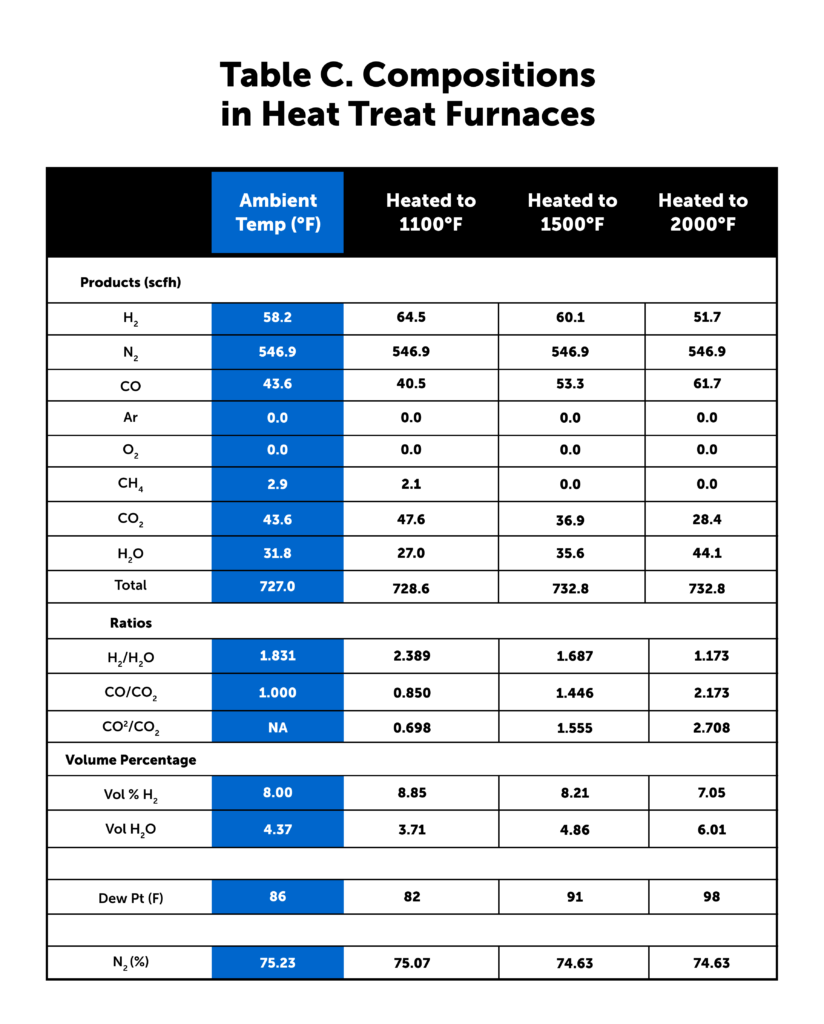
As an illustration, let us assume the following composition of the rich Exo gas (with a 7:1 air to natural gas ratio) at ambient temperature just before it enters the furnace:
Total volume: 727 SCFH
H₂: 8% (58.16 SCFH)
Dew Point 86°F or 4.37% (31.77 SCFH)
CO: 6% (43.62 SCFH)
CO₂: 6% (43.62 SCFH)
CH₄ : 0.4% (2.91 SFH)
Balance N₂ (%)
75.23% (546.92 SCFH)
Table C shows how the composition changes once it reaches the high heat section of the furnace where parts are being thermally treated. The column highlighted blue shows the composition of Exo gas as it is about to enter while it is still at the ambient temperature. The next three columns show the composition of the Exo gas in the high heat section of furnaces operating at three different temperatures depending upon the heat treat application — 1100°F like annealing of copper, 1500°F like annealing of steel tubes, and 2000°F like copper brazing of steel products. The H₂ to H₂O ratio decreases as temperature increases.
Other general comments on Exo generators:
Generally, they are horizontal.
Size ranges from 1,000 to 60,000 SCFH.
Rich Exo generators use Ni as a catalyst in the reaction chamber. Lean Exo does not.
Lean Exo generators typically operate at a 9:1 air to natural gas ratio. There is no carbon/soot buildup.
Rich Exo generators typically operate at a 7:1 air to natural gas ratio. Below about 6.8 and lower ratios, soot/carbon deposits start appearing that require carbon burnout as part of the maintenance procedure.
Table C. Exo gas compositions in heat treat furnaces
Conclusions
A walkthrough of the entire cycle of gas production to cool down to use in the high heat section of the furnace clearly shows that as temperature changes, so does the Exo gas composition for any air to natural gas ratio.
Having a well-controlled composition of Exo gas requires the following:
Well-controlled composition of the natural gas used
Air supply with controlled dew point
Highly accurate air and natural gas mixing system
Highly controlled and maintained cooling system
A reliable ORP analyzer or the H₂ to H₂O ratio analyzer as part of the Exo gas delivery system.
Protecting metallic workpieces is paramount in heat treating, and in order to do this, the atmosphere created by Exothermic gas must be understood, both in the cool down phase and within the heat treat furnace. For further understanding of the good progress made in the improvement of Exo generators, see Dan Herring’s work in the reference section below.
Harb Nayar is the founder and president of TAT Technologies LLC. Harb is both an inquisitive learner and dynamic entrepreneur who will share his current interests in the powder metal industry and what he anticipates for the future of the industry, especially where it bisects with heat treating.