Heat Treat Radio #132: Must-Attend Heat Treat Events of 2026 and Beyond


In this episode of Heat Treat Radio, host Heather Falcone sits down with Doug Glenn, publisher of Heat Treat Today, to break down the most important heat treat industry events on the horizon. From the massive international state of the THERMPROCESS trade show to the technical knowledge of Furnaces North America, they explore where those in the industry can learn, network, and grow. The conversation also highlights Heat Treat Today’s own events, including Heat Treat Boot Camp and Helium Leak Detection seminars. Together, they offer practical guidance on choosing the right events to stay engaged and informed in today’s heat treating landscape.

Below, you can watch the video, listen to the podcast by clicking on the audio play button, or read an edited transcript.




The following transcript has been edited for your reading enjoyment.

Introduction (00:05)

Heather Falcone: Hi, I am Heather Falcone and welcome to Heat Treat Radio. Today we are talking about a variety of upcoming events in the industry in 2026 and beyond. Joining me today is Doug Glenn, publisher of Heat Treat Today, and longtime host of Heat Treat Radio. Doug has had a front row seat to this industry for years, from the technical side to the people driving it forward. He’s also someone that I consider a mentor and a friend. I’m looking forward to digging into this conversation with him.

It’s an honor to sit down together with this one, Doug, as it’s kind of a bit of a hand off and a nod to the legacy that you’ve built here.

Doug Glenn: It’s a pleasure, and I couldn’t think of a better person to hand it off to. Heather, you’re doing great, and I appreciate you taking the time to do it and having the courage to do it.

Heather Falcone: Obviously, you have recorded over a hundred episodes, so I have so much to learn for you. Thank you so much for trusting me with this.

Key Events for 2026 and Beyond (1:19)

Heather Falcone: Doug, walk us through 2026 and beyond. We have so much going on for events. What are the key events that people should have on their radar?

Doug Glenn: We often say at Heat Treat Today that we believe people are happier, and they make better decisions when they are well informed. Our whole goal is to make people happy by giving them good information so they can make better decisions, and that that always works well. We do that in a variety of ways. Primarily it’s through our print publication — the technical articles that go out in that print publication. Our most popular product is our print publication. Most of that deals with heat treating, thermal processing, technologies, materials, etc.

But there’s also the element of continuing to sharpen your saw, as Stephen Covey says; keep yourself fresh. To that extent, attending industry shows, events, and educational seminars is helpful.

There’s a there’s a big show coming up in Germany in 2027. It’s called THERMPROCESS, but it’s actually one of four events that are all metals related, so we will talk about that whole quartet of shows. I will also talk about Furnaces North America because it is the leading thermal process/heat treat event of 2026. Then also we also have two Heat Treat Today events that I think might be helpful. Our Heat Treat Boot Camp, and then also our Helium Leak Detection seminars.

Those are the events I’m going to talk about today, but there are more events than that. If you are interested in learning more about important industry events, visit our website, heattreattoday.com, and look under Resource tab. There is the Industry Events calendar. That would be a real good place to start because we try to put all of the events that we think are important to most heat treaters and suppliers of the industry.

It’s important to note, when we talk about heat treat, we have to be very careful. We are not only talking about commercial heat treaters. That’s only about 10 to 15% of the audience that we reach. We are talking about captive heat treaters. That’s who Heat Treat Today is meant to be helpful to.

Heather Falcone: Reaching the broader industry at large is always our goal. Making sure that everyone has access to this. When you have an in-house heat treat operation, sometimes you can be even more isolated. So getting those companies exposed to as much information and data as possible.

THERMPROCESS 2027 (4:26)

Heather Falcone: Speaking of that, if someone can only commit to one or two events this year, I think we should really start with THERMPROCESS, because that one kind of rises to the top. We can unpack that a little bit first.

Doug Glenn: I think that’s a really good idea. The show itself, THERMPROCESS 2027 (thermprocess-online.com), is only one of four [in a trade fair quartet]. That show does not take place until June 21–25 of 2027. It’s over a year away. But the reason we need to talk about it now is because, unlike shows here in the United States, this is a huge show, and if you want to exhibit there, which many of our listeners may be suppliers in the industry, applications need to be in by the end of May of this year, not next year. So I wanted to make sure people are aware of that.

To give you a sense of what’s going on in that event, I want to provide a site map of the campus where THERMPROCESS is taking place. First thing to know is that there are four shows altogether. It’s held only every four years in Dusseldorf, Germany. Looking at the map, they call it “The Bright World of Metals,” you’ll notice the four logos across the top, which are GIFA, METEC, THERMPROCESS, and NEWCAST.
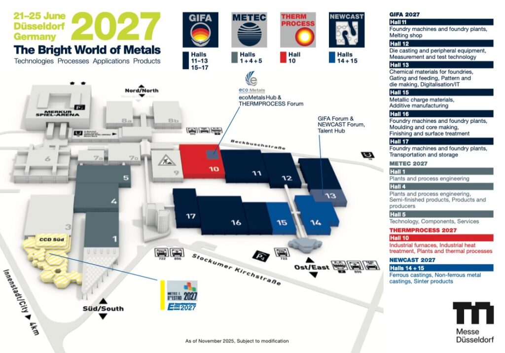
This is a huge campus. If you were to walk from the upper left corner, the Merkur Spiel Arena, all the way down to the east entrance, that would take you probably 10 to 15 minutes.

GIFA is a foundry show, and is located in halls 11 through 17. The dark blue on the map is all GIFA.

METEC is the gray on the map, halls 1, 4, and 5. This show is basically steel making, metallurgy, etc.

THERMPROCESS is in one hall, hall 10, and it’s the largest hall. It’s larger than any heat treat show here in the United States by far.

NEWCAST is basically a metallurgy show, steel processing, some forging as well. That’s in halls 14 and 15.

This show is open five days, from 9 a.m. until 5 p.m., all five days. If you were to spend your time walking through this show, it would basically take you all five days to go through this. It’s a huge event.

Let me give you a sense of this size. The total attendance for this entire event for 2023, which was the last one that they had, was 63,000 attendees. Even if you divide that by four, because there’s four different shows, that’s almost 16,000 people per show. To give you a sense of size difference in the United States: our biggest heat treat show, typically Furnaces North America or the ASM Heat Treat Show, attendance is no more than 2,500 people, including exhibitors and everything. You can get a sense that this is the right show.

It’s held in Dusseldorf, Germany. Germany of all countries in the world knows how to do trade shows. There are booths in these halls that are double decker booths, large booth displays. There are even restaurants on the upper level — it is a full event. Companies will spend millions of dollars just on this show.

My suggestion is, if you’ve never been to this show, or if you have a need for a full understanding in the thermal processing/heat treating industry, this is the premier event in the world, as far as I’m concerned. China has some big shows as well. I believe this one is more international. You will see people from all over Europe and the United States as well. 63,000 people total.

For just THERMPROCESS, there are 276 exhibitors, and the show takes up 8,400 square meters, which is about 90,000 square feet. Over on the Foundry side, obviously the biggest show here, taking up almost six halls, there are 854 exhibitors in about 41,315 square meters or 445,000 square feet of booth space. These are big shows.

Heather Falcone: It’s massive.

Doug Glenn: It is massive. There are companies exhibiting there from all over. Not only Western Europe, but Eastern Europe too, Turkey, Middle East, Saudi Arabia, China, India, etc. The United States, to be quite honest, is not always that well represented.

I think this is probably one of the more important things that I wanted to mention about this event. Heat Treat Today is promoting and sponsoring a pavilion there at THERMPROCESS. If you would like to be part of that pavilion, you can call me and we’ll see what we can do.

It’s a big deal, it’s a big show. May 31 of this year is the exhibitor deadline. For those of you who are interested in attending, which I highly recommend, thermprocess-online.com is the website.

If you’ve never been to Dusseldorf, it’s definitely worth going just to see Dusseldorf. There’s this place in Dusseldorf, a section of the town called the Altstadt, which is the old city. It’s a great place, hundreds of restaurants and great to experience the culture. It’s worth it after the show ends.

Also, the public transportation in Germany is very good. There are trams that run, which make it pretty convenient to get to the exhibit hall.

Heather Falcone: What kind of company roles do you think would be best suited to attend THERMPROCESS? Who do you think would most benefit from this event?

Doug Glenn: You would want more of your upper management personnel attending this event, not so much your furnace operators. You could do that — it would not be a problem taking the furnace operators over there. But it’s typically more engineers and up. One big difference between this show and most shows in Germany compared to shows in the United States: there is not a conference associated with it. They do offer some technical presentations, typically five or six a day in the small auditorium on the show floor. So you might get 30 different technical presentations, but this is primarily a trade show. It is a show where people sit down in their meeting rooms in their booths where they can close the door and have a private meeting, and they buy and sell there.

This is a show where if you want to do business, this is the premier event. In my 30 plus year experience, this has been the most impressive show, for thermal processing/heat treating, so I highly recommend attending.

Furnaces North America (14:28)

Heather Falcone: That’s a great point that you brought up, the difference between a trade show and the technical presentations. Compared to Furnaces North America (FNA), it’s a whole different ball game.

Doug Glenn: FNA is October 12–14, 2026 in Indianapolis. The website for that event is furnacesnorthamerica.com.

The difference is marked between THERMPROCESS and FNA. It’s just a whole different category in a variety of ways. The number of exhibitors is going to be somewhere in the range of 150 to 200, maybe right on the upper end. The trade show hours are typically a little bit shorter, maybe 11 a.m. to 5 or 6 p.m. It’s only a two-day show, not a five-day show. And there are a lot of technical sessions that are held. There’s a much better opportunity for more formal learning, if you will, where you can go to some classroom environments.

Furnaces North America is owned and operated by the Metal Treating Institute (MTI), which Heather and I are both members of, which is great. MTI is the world’s largest association of commercial heat treaters. While MTI is commercial heat treaters, Furnaces North America is really intended for captive heat treaters, as well as commercial heat treaters, to help advance the technology, knowledge of processes, and materials in the North American market.

It is a good event. It starts on a Monday night, the 12th of October, with a nice opening reception. Then Tuesday is a full day of conferences and the trade show. Wednesday, the conferences begin again in the morning, and then the trade show is open until around 2 p.m. So it’s a rather abbreviated show compared to THERMPROCESS.

Heather Falcone: It’s one of the more unique events because often, when you’re at a trade show, you do want to try and get some learning in, but you also want to get out and see the vendors on the floor. So they’ve set it up really well so that you never have to miss a concurrent session. In fact, they don’t even have the trade show floor open during the conferences. So, it ensures the exhibitors do not have to leave the trade show to attend session, and it lets people attend sessions without feeling guilty that they’re not out there hitting the booths at the trade show.

Doug Glenn: Exactly, they can actually go and do some of the learning as well. If I remember correctly, Heather, you’ve been involved with program development of FNA in the past.

Heather Falcone: Yes, I tend to do a session or so. Last time I think I talked about industry involvement, which is similar to the topic today. Getting involved in the industry is one of the best things you could do for yourself and your company.

Doug Glenn: That’s FNA in a nutshell. There are still some booths available. Although I don’t anticipate that will last long. Call or go to furnacesnorthamerica.com to check in on that, or contact me or Heather, and we can steer you in the right direction.

Heather Falcone: I honestly believe anyone would benefit from going to FNA because of the technical sessions. There’s a lot of learning to be had, even down to someone that’s more operational. It’s not just meant for that owner level. It’s pretty approachable.

Doug Glenn: I would agree. The expense of going to FNA is also substantially less than the expense of going to THERMPROCESS over in Germany. So you do see a good number of shop floor personnel at this, but it is also a good place to send your upper management personnel, depending on the size of your company, and your decision makers, as far as capital expenditures go. It is a good place to bring those people. You can gather a lot of information in a very short time walking around this show.

Heather Falcone: You can cover a lot of ground and really get some good relationship and networking going. It’s a great setup.

Heat Treat Today Events (19:20)

Heather Falcone: Let’s discuss the Heat Treat Today events, I think that there’s some truly unique offerings.

Doug Glenn: While Furnaces North America is not a Heat Treat Today-owned and operated event, we are the exclusive media sponsor of the event. But Heat Treat Today also has its own events.

Firstly, we have our most fun event, which is called Heat Treat Boot Camp. It was a brainchild of mine quite a few years ago because I tend to have a mile wide and an inch deep knowledge of the industry. I am no expert in any one area, but I have this experience of being here and absorbing over 30 years worth of information and relationships. So I thought to myself, wouldn’t it be nice to be able to share some of that information with people who are just wanting to get their heads wrapped around the North American heat treat market? What is it, who’s there, what are we doing, what are the materials — all that good stuff.

So we put together this event called Heat Treat Boot Camp. It is not heavily technical — you don’t need to know metallurgy or anything of that sort to attend. And it’s not just focused on any one piece of equipment, any one company’s equipment, or any one process, like brazing. It is cross-cutting. If you’re coming into the industry, or if you’ve been in the industry for a long time but have only focused on point X because that’s what you’re paid for, you can attend Heat Treat Boot Camp to get a broader view of this whole market. The added benefit of that is that you might find out there are other areas that your company could add that could potentially be profitable.

This is our fifth year coming up. It’s going to be held in Cleveland, Ohio, from Monday, September 14 to Wednesday, September 16, 2026. Our first four events were held in Pittsburgh, which is a great city. But we’re going to Cleveland this year, which should be very good.
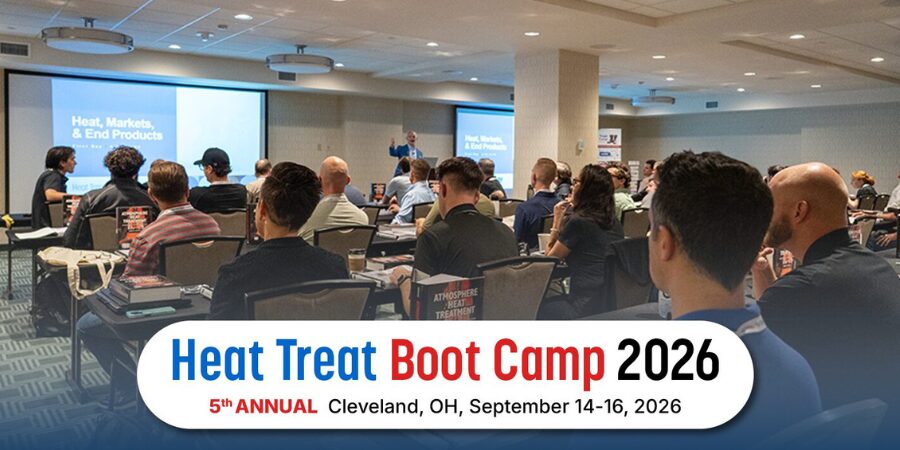
Here are the five things that we cover: heat treat markets, materials, processes, products, and players. By players, we mean, Who are the companies that manufacture the equipment… Equipment, components, supplies, materials? That’s the players.

We start the event on Monday night with a very nice opening reception. It’s usually just a nice time to get together and meet each other. Tuesday is the bootcamp day. It’s grueling, it’s a solid day of intensive learning, talking, slideshows, passing on knowledge. Thomas Wingens from WINGENS Industrial Consultancy is my partner and we teach the lectures. Thomas focuses more on the technical side because he’s a metallurgist. So he tries to explain processes and materials in terms that people who are not metallurgists can understand.

Wednesday morning is another half day of classes, and then it’s officially over at the end of the half day. However, we offer an optional heat treat plant tour afterwards on Wednesday afternoon. It is very cool actually because people who have never been to a heat treat shop can experience one.

When we were in Pittsburgh, we went to two. We alternated between Penna Flame Industries in Zelienople, PA, and Solar Atmospheres of Western Pennsylvania in Hermitage. Both are an hour from downtown Pittsburgh. Now that we’re going to Cleveland, we will be visiting Euclid Heat Treating, which is going to be a blast.

That’s bootcamp. It’s really worthwhile. You can visit heattreatbootcamp.com to learn more or you can go to our website, heattreattoday.com and look under events and hit Heat Treat Boot Camp. Feel free to register. If your company is bringing three or more people, get ahold of me and I’ll give you a discount code so you can get a little bit of a deal on registration. It’s a great event. It’s not overly technical. We had a couple company owners who bought furnace manufacturers and so have come to listen and learn. It’s meant for personnel in sales, marketing, and engineering to a certain extent as well. It’s really targeted at suppliers, but we have had quite a few captive heat treaters and commercial heat treaters who have also attended.

Heather Falcone: It’s a very approachable event and anybody should try it. This is a good opportunity for folks that are not necessarily exposed to a lot of the operations. Your HR people even. What’s a great chance to understand what your floor people are going through so that your HR can serve them better? Or accounting or anybody who hasn’t been exposed to the ins and outs of the industry. It’ll give them such a nice strategic understanding across the board without getting too heavy. Really good bang for the buck for such a short amount of time.

Doug Glenn: “Two plus years of industry knowledge in two days.” It’s like drinking out of the proverbial fire hydrant. Very worthwhile.

Helium Leak Detection Seminars (26:00)
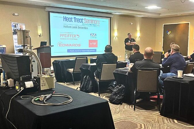
Heather Falcone: Let’s finish off by talking about Dave and the seminars.

Doug Glenn: Dave Deiwert is a helium vacuum leak detection expert who has been in the industry many, many years. These are single-day, in-person seminars where attendees will learn hands-on tips. Dave has leak detection equipment from several different suppliers. He will explain the theory behind helium leak detection, and provide solid, practical advice on how to do it. We had our first one this year in March in Charlotte, which was well attended.

The next helium leak detection seminar is in Philadelphia on June 10th, and then we’ll have one in Long Beach, California on August 12. Our final one is scheduled the day after the Furnaces North America event ends in Indianapolis. It’s going to be located right in that neighborhood. The idea was, go to Furnaces North America, stay an extra day, and attend the Helium Leak Detection seminar. It’s scheduled for the October 15 in Indianapolis.

If you’re interested in more information on those seminars, visit heattreattoday.com/leakdetectionseminar, all one word. ​

Closing Remarks(28:36)

Doug Glenn: It is a lot going on. It is a lot going on, and I want to give a shout out to our in-house events director who’s just taking on the role this year, Karen Gantzer. Karen’s been doing a great job squaring all this stuff away. We give her this wild thing and she’s taken it by the horns and is getting it done.

Heather Falcone: With a smile always!

We covered a lot of ground today. I’m really excited about what we’ve got to be able to offer to the industry. This has been unpacking these, helps them understand exactly what might speak to them individually.

It was a lot of fun spending a little time with you. You’re a mentor, you’re the legacy. You brought us over a hundred episodes of radio, I’m going to say it until I’m blue in the face!

Doug Glenn: Yeah, well it’s nice to not have to ask the questions. It’s nice to actually be able to answer them, so thank you. I appreciate you allowing me to come on.​


About the Guest

Doug Glenn
Publisher
Heat Treat Today

Doug Glenn is the founder and publisher of Heat Treat Today, a thermal processing industry consultant, and a longtime industry voice and conference speaker with over 30 years of experience. He spent two decades as publisher of Industrial Heating magazine, where he helped expand its global reach, and has played a key role in launching major industry events, including Furnaces North America.

For more information: Contact Doug Glenn at doug@heattreattoday.com.

Heat Treat Radio #132: Must-Attend Heat Treat Events of 2026 and Beyond Read More »
Keeping the Burners in Tune

Jim Roberts of U.S. Ignition engages readers in a Combustion Corner editorial about keeping industrial burners in tune — examining how everything from simple orifice plates to sophisticated burner control units (BCUs) and P-type radiant tubes drive efficiency and temperature uniformity in modern heat treating furnaces.

This editorial was first released in Heat Treat Today’s April 2026 Annual Induction Heating & Melting print edition.


In part 2 of this series (Aerospace Heat Treating, March 2026), we talked about how balancing the pressure can save gas and reduce emissions. So, how do they do it?

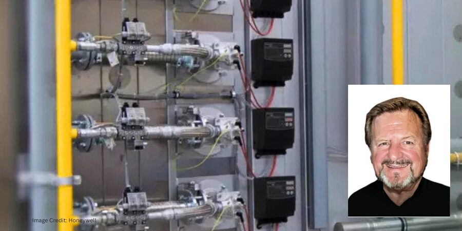
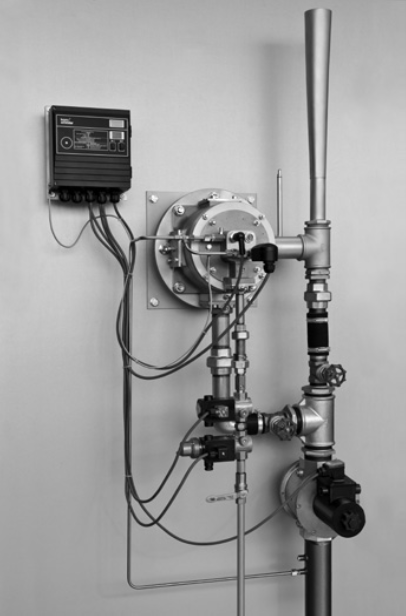
Figure 1. ECOMAX® with eductor and burner control unit BCU | Image Credit: Honeywell

There are some fairly sophisticated and exacting control systems that can use flow meters that compensate and monitor pressure fluctuations. The air and gas valving will then react to inputs from the orifice meters and pressure monitors. Some systems may even extract a sample of the flue gas at the exhaust, much like the sensors on your automobile catalytic converter. The use of these burner control units (BCUs) keeps burners tuned to exacting performance. A lab setup example of that technique is shown in Figure 1.

Other setups are quite simple and perform at their best on the normal setting. In other words, if the process temperature is 1850°F, engineers design burners to perform optimally at that temperature and for thermal input to be achieved 90% of the time. In this scenario, orifice plates and control valves set for that optimum performance hold the combustion system steady at that input; variations are minimal.

The burners may not run perfectly when coming up to heat, but that is hopefully a short-term situation, and as the furnace comes up to heat the burner, systems settle into a desired tune range. Think of these as the dragsters at a racetrack. We’ve all seen how they shudder and quake while waiting to go flat out down the racetrack. But when gas is pushed into them, they blow fire, smooth out, and go to unbelievable performance levels. Only we furnace guys would make that comparison… or maybe just this guy.

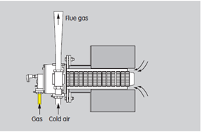
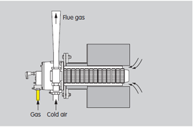
It bears noting that recirculation patterns can take on many variations depending on the type of heat treating you may be doing. Direct fired systems for stress relieving and straight up hardening operations use a high velocity direct fired system (Figure 2). That is where the aforementioned eductor pulls the flue gases out of the furnace and over the heat exchanger. Recirculation takes place in front of the burner in a high velocity stream exiting the nozzle. A percentage of the chamber gases gets pulled into that flue stream.

Figure 2. ECOMAX® in direct heating
systems | Image Credit: Honeywell
Figure 3. Examples of the design and the flue gas flow pattern | Image Credit: Honeywell
Figure 4. Schematics of P-type and double P-types tubes | Image Credit: Honeywell

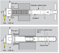
In the case of controlled atmosphere furnaces, where radiant tubes are utilized for the heating system, all sorts of different techniques exist. In the designs of recuperative recirculating style burners (i.e., FGR burners, flue gas recirculation), the tube designs are diverse and varied. Early designs of single ended tubes (SER) were the first to utilize recirculation designs (Figure 3).

Later, steel mills began to experiment and use P-type and double P-type tubes for strip annealing lines and galvanizing lines (Figure 4). You can see in these figures that the flue gases get pulled around, and we get the benefit of heat we have already generated and gas we have already burned. This creates a very good improvement in tube temperature uniformity and heat delivery. The arrows on the figures show the flow pattern of the gases.

So, in conclusion, there is no conclusion. Design improvements will continue to be made as long as we have requirements for efficient and emission-responsible operations in our heat treating plants and furnaces. Understanding that the world requires heat treating to be available for just about everything, and that we need to address those needs with ever-improving technologies… now THAT is pressure.

Till next time.

About The Author:

Jim Roberts
President
US Ignition

Jim Roberts president at U.S. Ignition, began his 45-year career in the burner and heat recovery industry focused on heat treating specifically in 1979. He worked for and helped start up WB Combustion in Hales Corners, Wisconsin. In 1985 he joined Eclipse Engineering in Rockford, IL, specializing in heat treating-related combustion equipment/burners. Inducted into the American Gas Association’s Hall of Flame for service in training gas company field managers, Jim is a former president of MTI and has contributed to countless seminars on fuel reduction and combustion-related practices.

For more information: Contact Jim Roberts at jim@usignition.com.

Keeping the Burners in Tune Read More »
Cómo domar a tu dragón

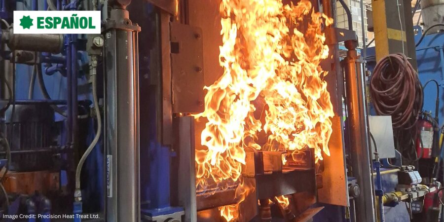
Cuando una carga se atasca durante el temple, cada segundo cuenta y las decisiones improvisadas pueden aumentar el riesgo. En esta entrega de “Martes Técnico“, Bruno Scomazzon, gerente general de Precision Heat Treat Ltd., describe un procedimiento de respuesta de emergencia paso a paso para este escenario, uno de los más peligrosos en el tratamiento térmico con atmósfera. Basándose en la experiencia real, esta guía tiene como objetivo ayudar a las empresas a desarrollar sus propios procedimientos eficaces para mantener la seguridad, controlar las condiciones del horno y coordinarse con los servicios de emergencia en situaciones de alto riesgo.

Este artículo informativo se publicó por primera vez en Ingles en Heat Treat Today’s February 2026 Annual Air & Atmosphere Heat Treating print edition.

Si tiene comentarios o preguntas sobre este artículo, háganoslo saber en: editor@heattreattoday.com.

Traducido por Víctor Zacarías. To read this article in English, click here.


Descripción del escenario

Se ha transferido una carga a la cámara de temple y el elevador está descendiendo al aceite, pero la carga se atasca y no se sumerge por completo. La puerta interior se cierra correctamente, y la puerta exterior (frontal) permanece cerrada.

Esta es una situación de altísimo riesgo que requiere el estricto cumplimiento de los procedimientos de emergencia. El objetivo es proteger: primero al personal (minimizar la posibilidad de lesiones o que la situación empeore), luego las instalaciones y, finalmente, el equipo.

1. Medidas inmediatas

NO abra la puerta exterior

Es posible que sienta la tentación de evaluar la situación, pero resista la tentación. NO se coloque frente a la puerta exterior ni justo al lado de ella, y nunca la abra mientras la carga esté “colgada”. Abrir esta puerta puede introducir oxígeno en una cámara caliente, lo que provocaría:

  • Explosiones o incendios repentinos (flash fire).
  • Pérdida de contención debido a deformación de la puerta o falla mecánica.

En casos extremos, la puerta exterior puede resultar dañada (arrancada, atascada o parcialmente abierta) y presentar llamas visibles. Esto requiere alertar inmediatamente a los bomberos.

Si la puerta exterior no se puede cerrar

En este caso, notifique inmediatamente a los bomberos e indíqueles que se preparen para una respuesta con espuma. NO permita el uso de agua. ¡Esto podría provocar reacciones violentas con el aceite o la atmósfera y propagar el fuego!

El personal de respuesta capacitado debe:

  • Colocarse el equipo de protección personal (EPP).
  • Preparar el equipo de extinción de incendios.
  • Estar listos para proteger los sistemas críticos hasta que lleguen los bomberos.

NO apague el horno.

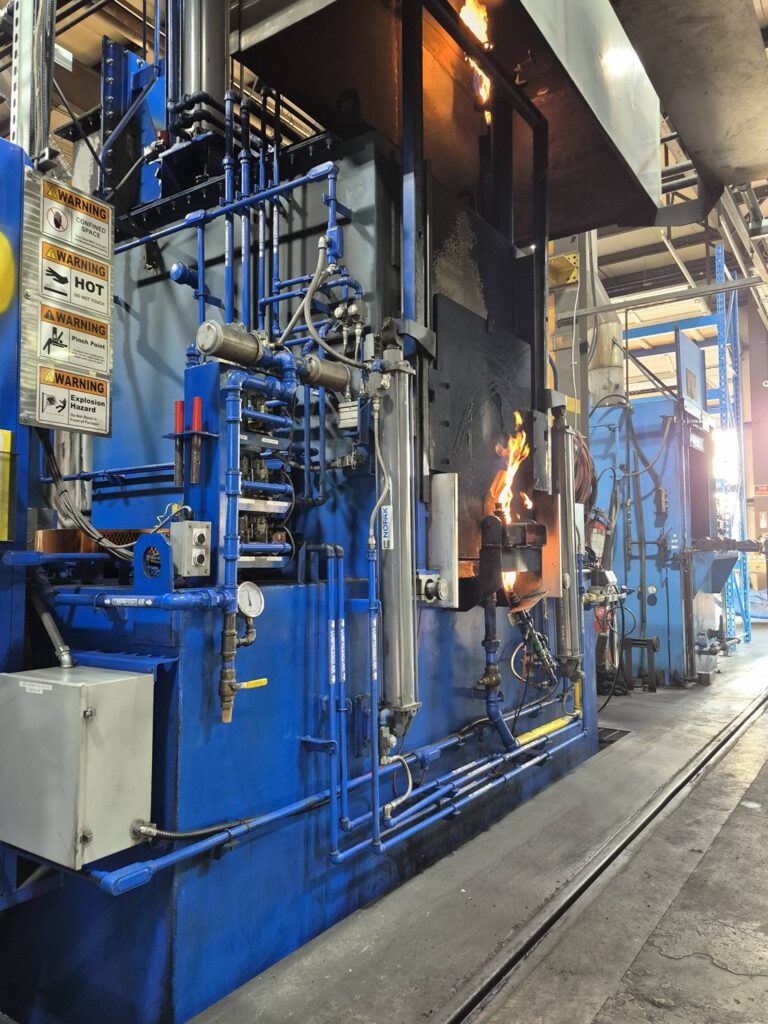
Figura 1. Horno de atmósfera durante su operación normal. | Image Credit: Precision Heat Treat Ltd.
Figura 2. Puerta del vestíbulo parcialmente abierta durante una simulación controlada para | Image Credit: Precision Heat Treat Ltd.

2. Mantener el suministro eléctrico

Para garantizar que los sistemas esenciales permanezcan activos, debe mantener el suministro eléctrico. Asegúrese de que los siguientes sistemas permanezcan activos:

  • Cambie el modo del horno de automático a manual. Esto evitará cualquier secuenciación del PLC que active automáticamente las puertas, los elevadores y los manipuladores.
  • Mantenga las llamas piloto encendidas.
  • Mantenga el enfriamiento del aceite en funcionamiento para evitar el sobrecalentamiento del tanque.
  • Apague los calentadores de aceite para evitar una carga térmica adicional en el tanque de temple.
  • Mantenga la agitación del temple a baja velocidad durante todo el proceso para ayudar a disminuir la temperatura en la superficie de interfaz entre la carga y el aceite. Esto evita la estratificación y disipa el calor por radiación en el aceite.
  • Mantenga el recirculador en funcionamiento.
  • Mantenga la instrumentación en funcionamiento para el monitoreo.

NOTA: La pérdida de estos sistemas elimina la visibilidad, el control de la atmósfera y las opciones de respuesta seguras.

3. Gestión de la atmósfera

Mantenga una atmósfera protectora y una presión positiva en el horno para evitar la entrada de oxígeno y la combustión incontrolada:

  • Ajuste el control del potencial de carbono a “0”.
  • Cierre el suministro de gas de enriquecimiento.
  • Cierre el suministro de amoníaco.
  • Cierre el suministro de aire de dilución.

Purga de nitrógeno

Estos pasos dependen de si se dispone de una purga de nitrógeno; se recomienda encarecidamente que esté disponible para todas las unidades con temple integral o de paso directo. Asegúrese de comprender cuánto tiempo tarda su horno en purgar completamente el gas endotérmico. Si bien la norma NFPA 86 recomienda cinco ciclos de purga, algunos expertos aconsejan prever hasta diez por hora en caso de emergencia. Cada horno debe contar con datos de purga establecidos en condiciones normales para que los operadores puedan actuar con confianza cuando el tiempo es crucial.

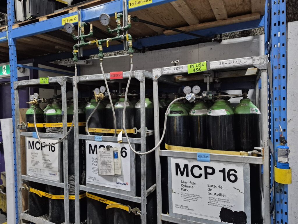
Figura 3. Suministro de nitrógeno utilizado para purga de emergencia y control de la atmósfera. | Image Credit: Precision Heat Treat Ltd.
  • Inicie inmediatamente una purga de nitrógeno (si está disponible) y manténgala durante todo el evento.
  • Utilice al menos el flujo mínimo especificado en su documentación. Si es seguro, se puede utilizar un flujo mayor para ayudar a desplazar los gases inflamables de las cámaras de calentamiento y temple.
  • Mantenga la temperatura del horno a 815°C (1500°F) durante la purga.

Pueden quedar espacios residuales de gas Endo atrapados en zonas con poca ventilación. Si la temperatura de la cámara desciende por debajo del punto de ignición antes de que se haya desplazado todo el gas inflamable, la entrada de oxígeno podría provocar una explosión. En algunos casos, el Endo atrapado y los desequilibrios de presión pueden causar fugas repentinas, en las que se expulsa aceite o gas debido a la acumulación de presión interna.

Después de la purga

El objetivo de la purga con nitrógeno es desplazar el gas endotérmico con una atmósfera inerte, manteniendo una temperatura elevada para facilitar la combustión de los gases inflamables residuales y prevenir la formación de mezclas peligrosas. Este proceso debe garantizar una presión positiva en todo el horno.

  • Una purga seguida de enfriamiento por inmersión de nitrógeno es un método válido si la purga se ha completado de forma verificable.
  • Según el tamaño del horno y la velocidad de enfriamiento:
  • Los hornos más grandes pueden enfriarse lo suficientemente lento como para completar la purga.
  • Las unidades más pequeñas o de enfriamiento más rápido pueden requerir un breve mantenimiento de la temperatura antes del enfriamiento controlado o el enfriamiento por inmersión.

NOTA: Una vez que la carga suspendida se enfríe a una temperatura segura (aproximadamente 65°C), realice el apagado estándar del equipo.

Sin nitrógeno (en Endo)

Si no hay purga de nitrógeno, o esta es insuficiente, la única opción es dejar que la carga acumulada se enfríe en el vestíbulo mientras se continúa quemando Endo y se mantiene la temperatura del horno a 1500°F. Una vez que el vestíbulo/tanque de aceite se enfríe por debajo de 150°F y haya pasado el peligro, inicie el apagado estándar del horno.

4. Gestión de la seguridad

  • Alerte inmediatamente al cuerpo de bomberos local. Si la situación se vuelve incontrolable o si existe alguna duda sobre la capacidad de mantener el control, evacúe las instalaciones y espere a que lleguen profesionales capacitados. La seguridad del personal de la planta es primordial.
  • Notifique al departamento de seguridad de la planta y a la administración del sitio.
  • Evacúe a todo el personal no esencial del área de tratamiento térmico.
  • Informe a todos los departamentos que se está produciendo un incidente de alto riesgo.

Los bomberos son más eficaces cuando conocen sus instalaciones antes de que ocurra una emergencia. Asegúrese de que conozcan la distribución de sus operaciones, incluyendo:

  • Ubicación y tamaño de los tanques de aceite
  • Paneles eléctricos
  • Válvulas de cierre de gas
  • Zonas calientes

5. Periodo de enfriamiento controlado

  • Mantenga la protección con atmósfera durante todo el evento.
  • NO abra las puertas hasta que la temperatura del vestíbulo sea baja y estable.
  • El tiempo de enfriamiento dependerá de la masa de la carga y la retención de calor. Prevea cinco horas o más.
  • Utilice la estabilidad de la presión del horno, las observaciones de los efluentes y el comportamiento de los gases como indicadores indirectos de la temperatura.

6. Procedimiento de recuperación de la carga

  • Una vez enfriado y estabilizado, realice el apagado estándar, comenzando con la eliminación del gas endotérmico, si corresponde.
  • NO intente retirar la carga manualmente hasta que el sistema esté verificado como seguro.
  • Solo el personal de mantenimiento puede recuperar la carga, utilizando equipo de protección personal (EPP) y las herramientas adecuadas.

7. Familiarización con el cuerpo de bomberos

Toda instalación debe establecer una buena relación con el cuerpo de bomberos local antes de que ocurra una emergencia. Procure revisiones anuales e identifique lo siguiente:

  • Número de hornos
  • Volumen de los tanques de aceite de temple para extinción de incendios
  • Ubicación de las zonas calientes y los paneles de control
  • Puntos de parada de emergencia

Las puertas atascadas suelen deberse a fallos en las válvulas neumáticas. Cerrar el suministro de aire comprimido y purgarlo puede permitir que el mecanismo se reinicie. Consulte siempre el manual del equipo o al fabricante antes de intentar cualquier solución.

Considere que el inspector de bomberos que realice las revisiones no es necesariamente quien acudirá a combatir los incendios; capacite a quienes sí lo harán.

Protocolo posterior al incidente

Antes de volver a poner en funcionamiento el horno, asegúrese de:

  • Realizar una investigación formal.
  • Identificar y corregir la(s) causa(s) raíz.
  • Documentar todos los parámetros clave y las acciones tomadas.
  • Capacitar nuevamente a los operadores según sea necesario.

Señalización del horno

Es probable que un operador lea el plan de seguridad, pero podría olvidar un protocolo vital durante una emergencia. Contar con advertencias claras y llamativas, impresas y colocadas en el panel, que el operador pueda retirar y utilizar en caso de emergencia, puede ser de gran utilidad.

Reflexiones finales

No podemos predecir todas las consecuencias. Ningún procedimiento puede contemplar todas las variables posibles en una emergencia real. Una vez que un evento se pone en marcha, lo único que podemos hacer es responder con el mejor criterio, capacitación e intenciones, priorizando siempre la seguridad de las personas.

Este documento pretende ser una referencia práctica: una guía estructurada elaborada con esmero, experiencia real y buenas prácticas. No es una solución universal, sino una herramienta para ayudar a los equipos a crear o mejorar sus propios procedimientos eficaces y a responder de forma adaptativa en situaciones de alto riesgo.

La preparación contra incendios es esencial en toda planta de tratamiento térmico. Los incendios ocurren, y no siempre son pequeños. Es fundamental saber cuándo actuar, cuándo evacuar y cuándo pedir ayuda. Los manuales de equipos proporcionan una base, pero la preparación mediante capacitación y planificación es la mejor defensa.

Agradecimientos: El autor agradecer a Daniel H. Herring, “The Heat Treat Doctor,” a The HERRING GROUP, Inc., y a Avery Bell de Service Heat Treat en Milwaukee por sus valiosas contribuciones.

Acerca del autor:

Bruno Scomazzon
Gerente General
Precision Heat Treat Ltd.

Bruno Scomazzon es el gerente general de Precision Heat Treat Ltd. en Surrey, Columbia Británica, Canadá, y cuenta con más de 40 años de experiencia en procesos metalúrgicos y operaciones de tratamiento térmico.

Para más información: Contacte a Bruno en bruno@precisionheattreat.com.

Cómo domar a tu dragón Read More »
The Jominy and Rapid Quench, Part 1: An American Story

In this two-part series, Dr. Gopal Nadkarni, an associate professor of mechanical engineering at the University of Akron, revisits the American origins and impacts of the Jominy test while exploring how rapid quenching technologies are exposing its limitations. Discover how a new approach builds on ASTM foundations to better reflect today’s high-performance cooling methods.

This informative piece was first released in Heat Treat Today’s April 2026 Annual Induction Heating & Melting print edition.


Introduction

For nearly a century, the Jominy End-Quench Test has shaped how North American engineers design alloys, specify steels, and heat treat critical components across automotive, oil and gas, heavy machinery, and aerospace industries. It involves one small piece of steel and a stream of water. Simple, repeatable, and powerful, it was revolutionary for its time. But it derived from a different world of manufacturing. Furnaces were batch loaded. Parts required hand transfer. Quenching utilized tanks with modest agitation — not high-pressure sprays, induction-to-quench lines, or high-performance water systems.

Today’s rapid quench technologies reveal a key limitation: the classic Jominy test can systematically underestimate what many steels are capable of under aggressive convective cooling. Why? Because film boiling — a vapor layer at the steel surface — chokes heat transfer right where it matters most.

In order to take advantage of a wider range of materials and processing methods, a shift in how to leverage this test is necessary. The discussion that follows elaborates on this American origin story of the Jominy’s test and what challenge the film boiling layer posed 75 years ago versus today.

Pursuing Performance: The Origins of the Jominy Test

In 1947, Fred P. Peters wrote in Scientific American that hardenability was no longer just a technical trend; it was a revolution changing how the steel industry did business. He was describing a shift in which clients wanted to move away from buying a grade based on chemistry specs alone to buying a product that would guarantee performance.

*Hardenability: the ability of a steel to harden to a certain depth. Hardness, by comparison, is the measurement of how hard a material is at a given location. High hardenability ensures desired properties and microstructure at a given depth for critical components; this leads to more efficient optimized part designs.

But there was a problem: Steelmaking was, and still is, a complex science with unavoidable variability arising from chemical, thermal, and metallurgical processes involved. From batch-to-batch, a single supplier could achieve different hardenability results. That variability caused headaches for manufacturers.

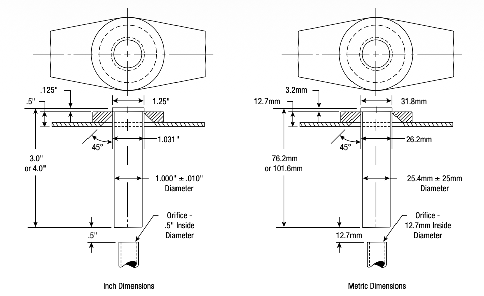
Two metallurgists working with General Motors, Walter Jominy and A.L. Boegehold, proposed an elegant solution: standardize the cooling conditions instead of chasing exact chemistry. Pinpointing the “maximum hardness at center” had been an estimate derived from submerging several steel bars of various diameters in a quench tank. Speaking to the Detroit Chapter of American Society of Metals, the metallurgists pushed for an end-quench test using a standardized one-inch round bar, heated uniformly, and quenched at one end with a water jet. Their practical solution replicated the range of cooling rates from the maximum cooling rate (water) at the quench face to the slowest cooling rate (air) at the other end of the bar. The resulting hardness profile became a “fingerprint” of that alloy’s hardenability.

That fingerprint changed everything.

Figure 1. Diagram of the Jominy End-Quench Test | Reference: ASTM A255-02

Metallurgists could now rapidly compare alloys from different suppliers or with minor chemistry differences. Additionally, design engineers could specify hardenability bands rather than tight chemistry limits. Steelmakers could adjust compositions and quickly verify performance. Scrap heats dropped. Costs fell. Customers gained predictable, repeatable results. ASTM A255 formalized the method, and the Jominy test became the global language of hardenability (Figure 1).

Known Limitations and Rapid Quench

Heat treaters know the Jominy test is a simplification. The specimen is a straight bar, not a gear or forging. Only one end is quenched. The cooling method represents one type of quench: water, not oil, polymer, or gas.

There’s also a compositional limitation; highly alloyed steels often show little variation along the four-inch test length.

But one limitation has taken on new importance in modern heat treatment: the vapor blanket.

The Vapor Blanket Problem

When red-hot steel hits water, a vapor layer instantly forms on the surface. This “Leidenfrost layer” acts like insulation. Heat transfer drops until the vapor film collapses and nucleate boiling begins.

That means the cooling severity at the Jominy face is not just “water quench.” It is water quench through a steam barrier.

So, the hardenability curve we measure reflects steel transformation behavior plus a boiling-limited surface condition. If that vapor layer is removed or shortened, the cooling rate at the surface rises, and the steel may harden deeper than the standard Jominy curve suggests.

Heat treaters know this problem firsthand. Agitated water tanks try to break up the vapor film, but removal is inconsistent. The result can be uneven hardening — the “spotty” surfaces everyone has seen. And the usual workarounds are to add alloy, carburize deeper, or accept extra process time and cost. In other words, the industry learned to design around the vapor blanket instead of eliminating it. The “Leidenfrost Layer” describes this insulating vapor blanket phenomenon that occurs when liquid meets a hot surface significantly hotter than its boiling point.

A Different Philosophy: Rapid Quenching

Over the past two decades, a new approach has gained traction: do not accept film boiling — remove it.

Researchers, such as Dr. Kobasko and Dr. Aronov, showed through modeling and experiments that high-velocity, high-pressure water flow can consistently suppress the vapor layer, a method known as Intensive Quenching™. This approach pushes the hot surface quickly into high heat transfer by removing the vapor film and has been referred to as High Convective Quenching, High-Pressure Convective Quenching, and Rapid Quenching.

The result is more than faster cooling.

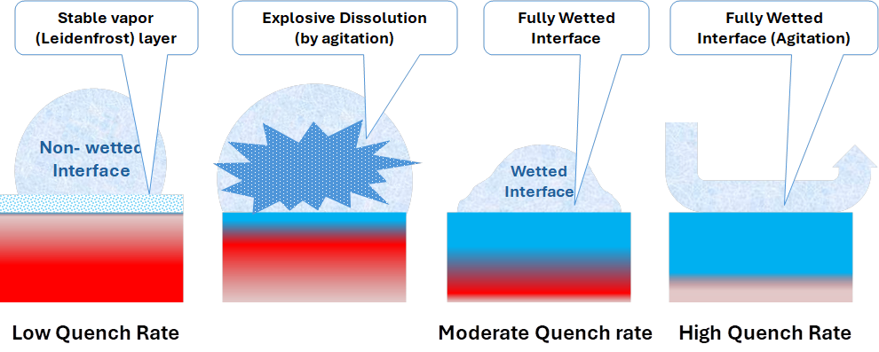
Figure 2. Quench rate and surface reactions

Early formation of a martensitic surface shell creates compressive stresses that enhance fatigue and wear resistance. Parts can show deeper effective hardening and improved surface performance without increasing alloy content (Figure 2). Some studies even suggest differences in martensite morphology (twinned morphology) compared to conventional quenching (lath morphology). This is not just “harder steel.” It is a different thermal-mechanical response at the surface.

Rethinking the Jominy Test

If quenching technology has changed, should the hardenability test evolve too?

Research at the University of Akron has shown that the standard Jominy setup itself forms a vapor layer. Raising the jet height does not eliminate it. That means the test measures hardenability under a boiling-limited condition, not under maximum achievable heat transfer.

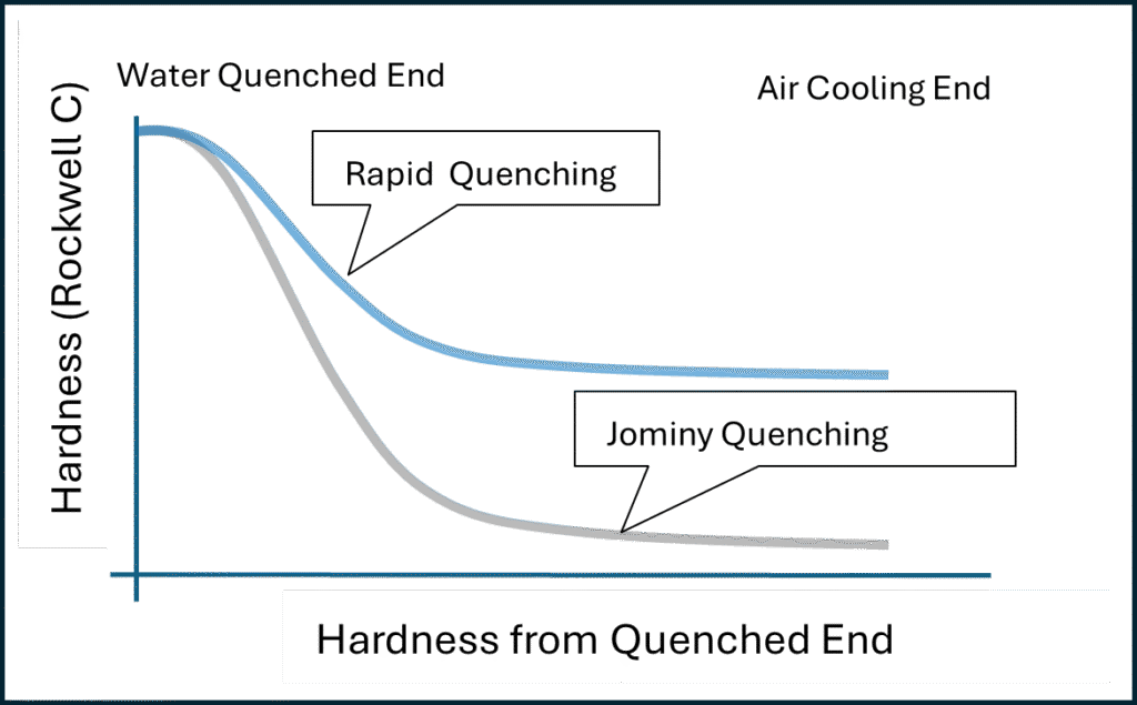
Figure 3. Standard vs. Rapid Quench Hardenability | Image Credit: Gopal Nadkarni

Working with industry partners, the university researchers developed a modified end-quench configuration that uses high-convective water impingement to strip the vapor barrier. The measurement philosophy remains Jominy-based i.e. measure hardness along the length of the bar. What changes is that the end of the flat bar is given a slight taper to allow it tightly seal into a chamber where a water jet is sprayed on the surface, much like a jet pressure washer. Modeling this scenario allows us to predict that the new pressure and flow conditions are sufficient to strip the vapor and keep it from reforming, thus creating conditions of maximum heat transfer without the continuous formation of the film. The old “umbrella” method of cooling does not ensure the removal of the vapor or film on surface. The result is a new method that reveals how steels behave under rapid quench — conditions increasingly used in advanced heat treat operations (Figure 3).

Why This Matters to Industry Now

For 75 years, engineers have relied on handbooks filled with Jominy curve diagrams. Those curves remain valuable, but they reflect a quenching severity rooted in mid-20th-century practice.

Today, heat treaters, steelmakers, and designers have a chance to expand that framework. A rapid-quench Jominy approach could help:

  • Optimize alloy design for modern quench systems
  • Improve simulation accuracy in digital twins
  • Reduce over-alloying and cost
  • Increase part performance and consistency

This is not about redefining hardenability. It is about recognizing that hardenability is expressed under a defined cooling boundary. As quenching technology advances, our standardized ways of describing steel response should advance with it.

In Part 2, we’ll look at how this modified Jominy approach aligns with ASTM philosophy, what simulation reveals, and how rapid quenching translates into real improvements for gears, heavy components, and other critical parts.

About The Author:

Dr. Gopal Nadkarni
Associate Professor of Mechanical Engineering
University of Akron

Dr. Gopal Nadkarni is an Associate Professor of Mechanical Engineering at the University of Akron and manages its Manufacturing Graduate Certificate Program. He brings extensive industry and innovation experience, having held previous leadership roles at industry and in technology ventures, with research and teaching focused on manufacturing, materials, and product design.

To contribute to ongoing industry-academia research regarding this topic, please contact Professor Gopal Nadkarni.

For more information: Contact Gopal Nadkarni at gnadkarni1@uakron.edu.

The Jominy and Rapid Quench, Part 1: An American Story Read More »
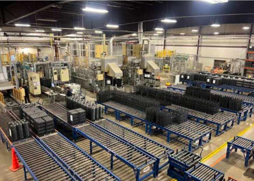
$100M Expansion Targets Engine Component Production Growth

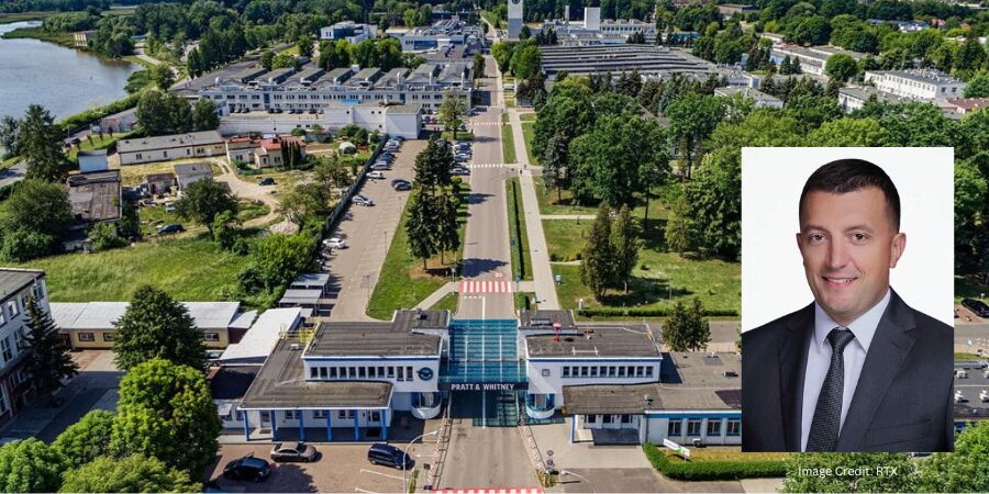
RTX’s Pratt & Whitney, a North American aerospace manufacturer headquartered in East Hartford, Connecticut, is investing $100 million to expand production capacity through advanced manufacturing processes, including heat treatment of forged engine components, to support increased output of commercial and military aircraft engines. The expansion is expected to strengthen supply for aerospace programs and improve throughput of critical engine parts used across global aviation fleets.

The investment will be made at the company’s facility in Rzeszów, Poland, where operations will be expanded to include additional processing capabilities and production capacity. The site supports manufacturing for several engine programs. including GTF™, F135, and F100 platforms, which serve both commercial aviation and defense applications.

Piotr Owsicki
General Manager
Pratt & Whitney Rzeszów

As part of the project, the company plans to add new capabilities focused on processing isothermally forged components, including heat treatment, sonic machining, and inspection operations. This expansion follows and supports the recently announced $200 million investment in a seventh isothermal forging press at Pratt & Whitney’s Columbus Forge facility in Georgia, U.S.

The expansion is intended to address growing global demand for aircraft engines and related components. “This investment reflects our continued commitment to increase production capacity for our [clients] and deliver more, faster,” said Piotr Owsicki, general manager of Pratt & Whitney Rzeszów. The capital project, expected to be fully operational by 2028, will enable a 30% increase in output of critical engine parts such as rotating compressor and turbine disks.

Press release is available in its original form here.

$100M Expansion Targets Engine Component Production Growth Read More »
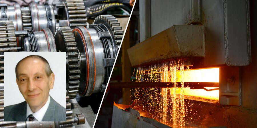
Vacuum Furnace Boosts Tool Steel Processing

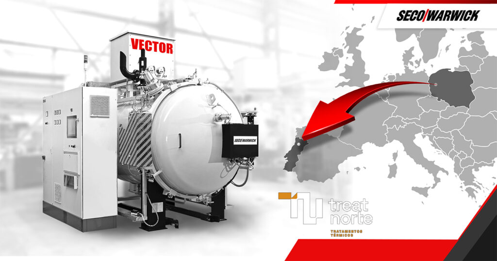
Treatnorte, a commercial heat treatment company, will add a new vacuum furnace to support vacuum heat treatment of tool steel, improving process control and consistency for components used in manufacturing applications.

Image Credit: SECO/WARWICK

The furnace joining Treatnorte’s machine park is a medium size system from SECO/WARWICK, a global manufacturer of heat treatment equipment with operations in North America. It is configured to provide a broad process range and production flexibility.

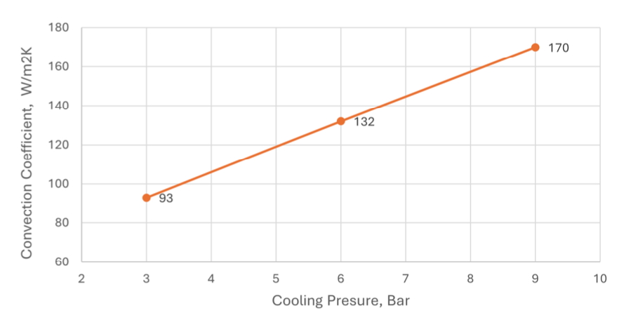
The round heating chamber allows processing of relatively large parts, while the combination of high-pressure gas quenching (HPGQ) up to 15 bar abs, combined with dedicated low-pressure carburizing (LPC) technology, enables complete process cycles for a range of steels used by Treatnorte’s clients. The furnace provides temperature uniformity, convection heating at lower temperatures, and directional cooling, supporting control of quenching processes for complex geometries.

The furnace configuration also incorporates FineCarb technology, SECO/WARWICK’s low-pressure carburizing solution carried out in a vacuum atmosphere, where carbon introduction is precisely controlled through successive pulses of carbon-bearing gases. This process allows for uniform and repeatable carburized layers with minimal part distortion and reduced cycle time.

The equipment will serve both the Portuguese and Spanish markets, where it will support ongoing tool steel heat-treatment operations. “The ability to independently perform vacuum hardening and carburizing processes significantly increases operations independence, shortens the supply chain, and allows for better quality control. FineCarb technology, combined with 15-bar gas quenching opens up opportunities for Treatnorte to win more demanding projects for [clients] in Portugal and Spain,” said Nuno Carvalho from Treatnorte.

Press release is available in its original form here.

Vacuum Furnace Boosts Tool Steel Processing Read More »

C/C Composite Fixturing: Optimizing Precision Brazing for Aerospace Components

Advanced carbon-fiber-reinforced carbon (C/C) composites are redefining fixturing performance in high-temperature aerospace heat treating and furnace brazing. In this feature article, Hirotaka Nagao, Ph.D., technical expert at CFC Design Inc., explores how C/C composites maintain strength and dimensional stability at extreme temperatures while reducing fixture mass, improving thermal uniformity, and increasing furnace productivity.

This informative piece was first released in Heat Treat Today’s March 2026 Annual Aerospace Heat Treating print edition.


The Challenge of High-Temperature Integrity

In aerospace heat treating, and specifically furnace brazing, traditional metal fixturing often acts as a bottleneck for productivity. While stainless steel and super-alloys like Inconel or Hastelloy are common, they lose significant strength and begin to deform at temperatures above 700°C (1292°F), making them suspect for precision fixtures. For vacuum brazing processes involving aluminum and copper radiators or oil coolers, maintaining precise dimensional tolerance is a critical requirement for part performance and safety.

The emergence of carbon-fiber-reinforced carbon (C/C) composites offers a transformative solution, as these materials maintain high strength and rigidity at temperatures exceeding 2000°C (3632°F).

The Evolution of C/C Composites

C/C composites consist of high-strength carbon fibers reinforcing a carbon matrix, a combination that provides a unique set of mechanical properties. These materials first appeared in the 1960s and found practical use in specialized aerospace applications, such as spacecraft nose caps, wing leading edges, and aircraft brake materials by the 1980s. Historically, the cost of C/C composites limited their use to government-funded aerospace programs, but modern manufacturing advancements have brought the price range within the scope of general industrial applications.

Compared to graphite, C/C composites possess several times the strength and elastic modulus while offering far superior fracture resistance. Unlike traditional ceramics like silicon nitride or zirconia, which are vulnerable to thermal shock and can be fragile to handle, C/C composites offer high toughness and excellent resistance to radiation and corrosion.

While C/C composites offer exceptional thermal stability, their implementation requires careful management of specific material sensitivities. The primary concern is oxidation; in oxygen-rich environments, the material begins to degrade at temperatures exceeding 350°C (660°F), necessitating protective coatings or inert atmospheres. Furthermore, the initial capital investment for C/C components is significantly higher than that of graphite or standard metals, though this is typically balanced by their superior service life.

In high-temperature vacuum or atmosphere furnaces, direct contact between C/C composites and iron-containing metals must be avoided above 1000°C (1832°F) to prevent eutectic reactions; this is managed through physical separation or the application of barriers like boron nitride. Finally, for particulate-sensitive environments like semiconductor manufacturing, the inherent tendency of C/C composites to produce carbon dust is mitigated by applying specialized carbon coatings to seal the surface.

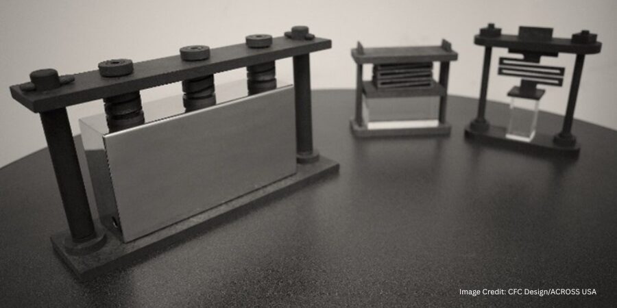
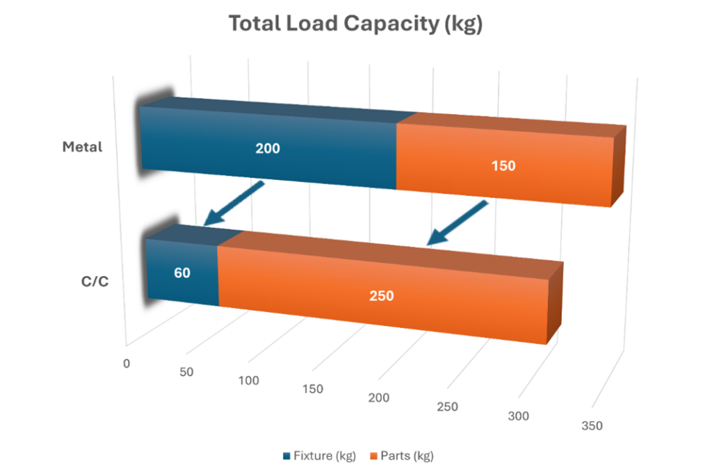
Figure 1. Comparison of total load capacity of C/C fixture and metal fixture | Image Credit: CFC Design/ACROSS USA

Material Performance: A Technical Comparison

The decision to switch from metal or ceramic to C/C composites involves a detailed understanding of the thermal and mechanical limits of each material class.

  • Heat-resistant alloys: Maximum service temperatures for standard heat-resistant alloys are often capped at 400°C (752°F) before mechanical properties degrade.
  • Super-alloys: Even advanced materials like Inconel and Hastelloy lose significant strength and suffer from permanent deformation above 700°C (1292°F), rendering them ineffective as springs or precision supports in high-heat environments.
  • Ceramics: While they offer high heat resistance, ceramics are vulnerable to thermal shock and can break when repeatedly cycled at temperatures exceeding 1000°C (1832°F). They also lack the toughness required for heavy industrial handling.
  • C/C composites: Advanced materials that combine carbon fibers with a carbon matrix offer an exceptional balance of lightweight strength and thermal resilience. These materials maintain their characteristics and mechanical strength from room temperature up to 2000°C (3632°F).

Structural Advantages of C/C Composite Fixtures

A primary advantage of C/C precision braze fixturing is the drastic reduction in “gross weight” within the furnace, which directly impacts the economics of the heat treat cycle.

  • Mass reduction: C/C material is approximately 20% the weight of metal, which drastically reduces the dead weight the furnace must heat.
  • Increased capacity: In a specific industrial application, C/C fixtures weighing 66 kg (145 lb) replaced 200 kg (440 lb) stainless-steel fixtures.
  • Loading efficiency: In a furnace with a 350 kg (772 lb) total load capacity, this weight reduction allowed the “parts weight” to increase from 150 kg to 250 kg per cycle — a 66% increase in productivity.
  • Productivity gains: The ratio of total fixture weight to total load capacity was reduced by 70%, enabling more components to be processed in a single cycle.
  • Energy efficiency: Reducing the fixture weight lowers the total heat capacity of the load, allowing for faster heating times and a drastic reduction in the cost of energy per part.

Thermal Uniformity and Defect Reduction

Traditional metal fixtures often require supplementary “dead weights” to apply constant pressure during the brazing process. These weights, which can reach 20 kg or more, introduce significant thermal challenges:

  • Thermal shadowing: Large metal weights tend to block radiant heat waves, creating “shadows” that compromise heating uniformity.
  • Defect rates: Inconsistent heating leads to defective brazed parts and necessitates spacing parts further apart to ensure uniformity, which further limits productivity.
  • C/C solution: The compact design of C/C fixtures, combined with lightweight springs (weighing only 70 grams), eliminates these thermal barriers. This allows for a decrease in the defect rate and an increase in total process quantity.

The Physics of C/C Spring Technology

To replace heavy dead weights, engineers utilize C/C spring technology to apply a constant load throughout the heating cycle. These springs maintain their force as temperature increases, and the brazing begins once the melting point of the filler metal is reached.

1. Continuous Fiber Coil Springs

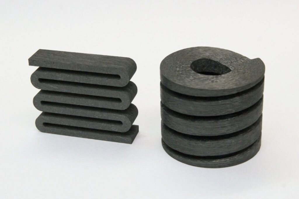
Figure 2. (left) New Z-type plate spring innovated for mass production and (right) continuous fiber coil spring

Modern C/C coil springs are manufactured such that the long carbon fibers are spirally continuous and not segmented during the machining process. Early C/C composite coil springs were fabricated by cutting shapes out of two-dimensionally reinforced long-fiber C/C blocks. This method had a significant drawback: the reinforcing fibers were segmented during processing. Because the fibers were cut, the material could not exhibit its full structural strength, leading to a decrease in the spring constant after repeated use in high-temperature environments.

To compensate for these limitations, a proprietary spring type was developed using long carbon fibers that are spirally continuous in one direction (Figure 2). Because these fibers are not segmented, they fully demonstrate their role as a reinforcing medium, resulting in a product that maintains a stable spring constant even after repeated cycles exceeding 1000°C (1832°F).

  • Durability: Because the reinforcing fibers are not cut, the spring fully demonstrates its strength and maintains a stable spring constant even after repeated use.
  • Performance: A single carbon spring can generate up to 24.5 kg of force while weighing only 26–84 grams. This provides an equivalent load to metal weights that are hundreds of times heavier.

2. New Type C/C Composite Spring: “Z-Type” Spring

While continuous-fiber coil springs are highly effective, they possess inherent manufacturing disadvantages. Neatly arranging long fibers in a spiral shape is complex and difficult to scale for mass production. Furthermore, because the spring size depends on specific mold dimensions, it has historically been difficult to produce a diverse variety of spring strengths and sizes.

To address the mass-production limitations and molding size constraints of coil-shaped springs, the “Z-type” plate spring was engineered to support large loads using a more efficient manufacturing process (Figure 2). Instead of a coiled architecture, this spring is fabricated in a zig-zag, serpentine pattern using a C/C composite plate.

  • Material design: The zig-zag pattern is achieved by using laminated plates where short carbon fibers are randomly oriented in a two-dimensional XY plane.
  • Shear modulus: This random orientation dramatically improves the in-plane shear modulus, allowing the Z-spring to support larger loads and offer a larger deflection allowance than coil-shaped versions.
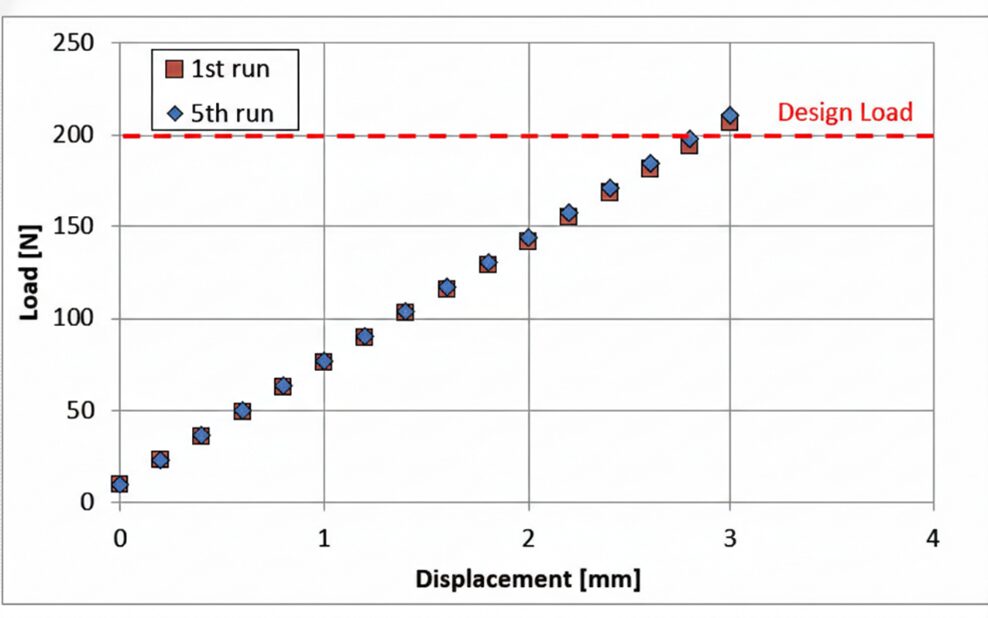
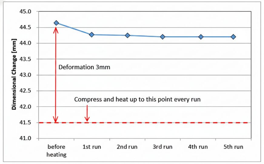
  • Stability: In repeated load tests at 1250°C (2282°F), Z-type springs show a minimal 1% decrease in natural length during the first run and zero “setting” or deformation in subsequent cycles.
  • Mass production: Unlike coil springs, Z-type springs can be mass produced through water-jet machining from large C/C laminate plates.

Figure 3 shows the displacement-load curve of the Z-type C/C composite spring. From this figure, satisfactory spring characteristics are exhibited, even in repeated load tests.

Figure 3. Displacement-load curve of the Z-type C/C composite spring | Image Credit: CFC Design/ACROSS USA
Figure 4. Z-type C/C composite spring dimensions after heating and subsequent heating runs | Image Credit: CFC Design/ACROSS USA

After heating the Z-type C/C composite spring in a compressed state at 1250°C (2282°F) for 30 minutes in a nitrogen atmosphere, spring characteristics were measured at room temperature and a repeated heating test was performed.

A decrease of about 1% in the natural length was observed only during the first heating run. However, the natural length did not change even if the heating was repeated after, and it was found that there was no setting at all.

Compared to coil-type C/C composite springs, C/C composite springs made from short-fiber reinforcing materials are characterized by very few shape restrictions and various configurations are achievable.

Advanced Applications: Clips, Bolts, and Large-Scale Fixtures

Figure 5. C/C clips in a sandwich arrangement. This design enables load application while bypassing the need for intricate custom fixture. | Image Credit: CFC Design/ACROSS USA

The versatility of C/C machining allows for specialized components that simplify complex furnace operations:

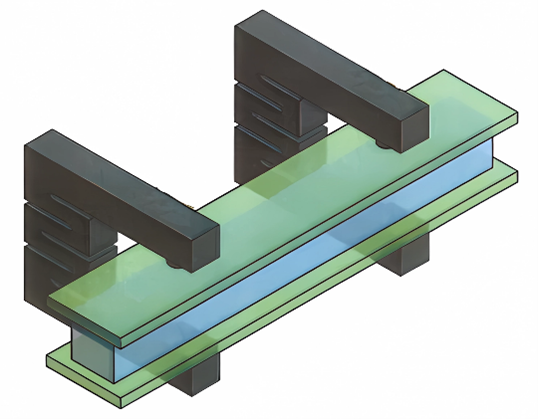
  • C/C clips: Developed to simplify fixturing, these clips act as integrated springs that sandwich parts directly, eliminating the need for complicated, heavy clamp structures.
  • Thermal expansion absorption: In high-temperature furnaces, graphite heaters can deform under their own weight or fail due to thermal stress at joint points. C/C bolts with a “notched” design act as integrated springs to absorb dimensional changes caused by thermal expansion, preventing damage to electrodes and joints.
  • Large-scale serpentine springs: Z-springs can be manufactured in large serpentine shapes, achieving deflections of up to 22% of their natural length (e.g., a 50 mm deflection on a 230 mm spring) while maintaining satisfactory spring characteristics.

Improving Plant Economics

The transition from heavy metal fixturing to high-performance C/C composites is no longer just a technical preference but a necessity for modern plant economics. For aerospace components that demand zero-distortion and high-precision brazing, C/C fixturing provides the thermal and mechanical stability required for 21st-century manufacturing.

About The Author:

Hirotaka Nagao, Ph.D., is a technical expert at CFC Design Inc. specializing in the development of advanced carbon-fiber-reinforced carbon (C/C) composite materials. With a doctorate in material science, his research focuses on high-temperature applications and improving production efficiency through innovative C/C fixture and spring designs for furnace brazing and heat treatment environments.

For more information: Contact ACROSS USA at www.acrosscc.com.

C/C Composite Fixturing: Optimizing Precision Brazing for Aerospace Components Read More »
MTI Member Profile: DOWA THT America, Inc.

DOWA THT America, Inc. (DOWA THT) was established in 1997 and began operations in 1998 in Bowling Green, Ohio, as a subsidiary of Japan’s DOWA Thermotech Co., Ltd. The company was founded with the goal of meeting the North American demand for advanced heat treatment, initially targeting the automotive industry and expanding over time to serve the construction, agriculture, and green energy sectors.

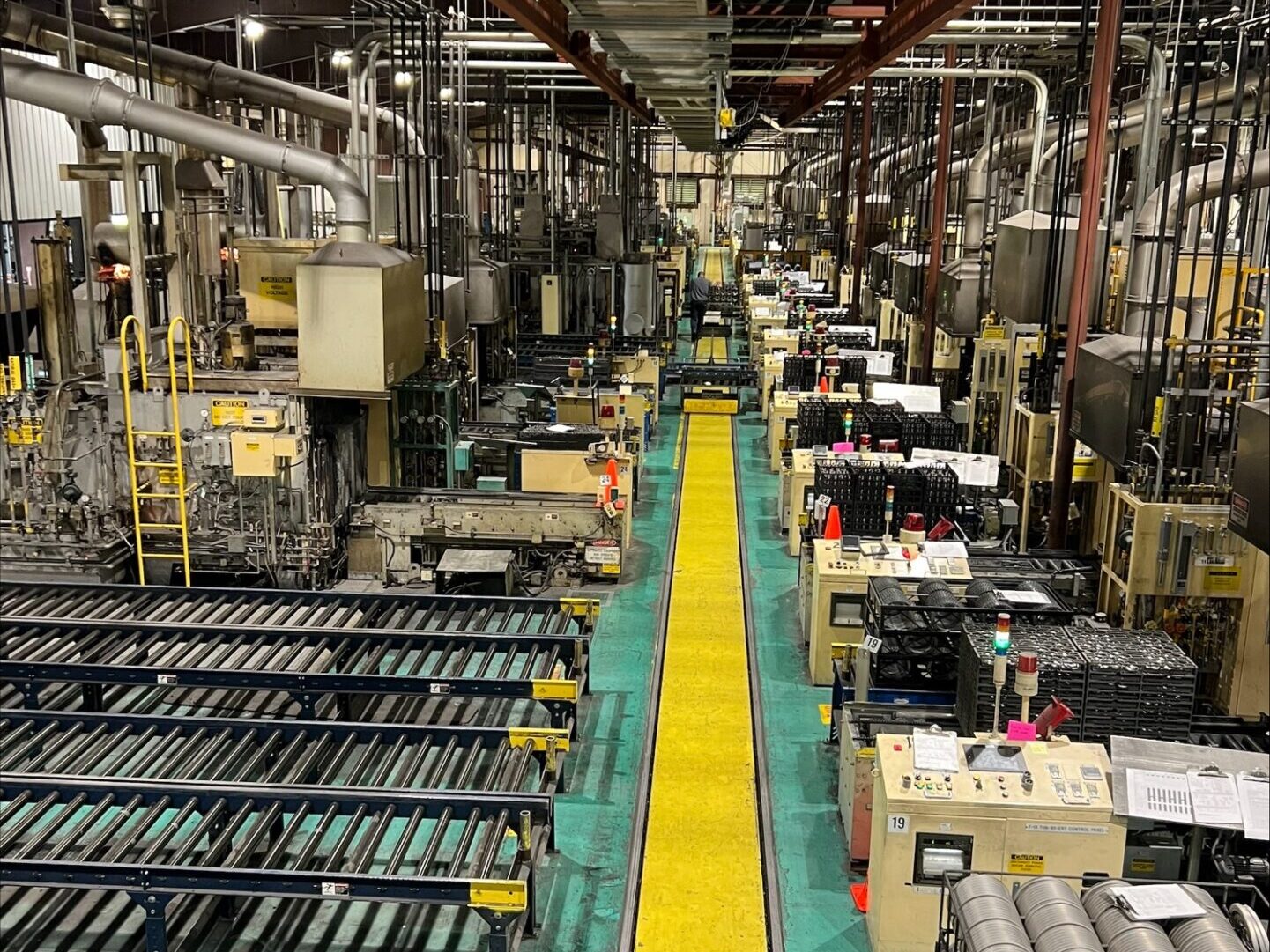
DOWA THT Batch Furnace Line | Image Credit: DOWA THT

DOWA THT operates two independent divisions. One division is the Commercial Heat Treatment Division, which is operated locally and has been expanded four times since the original building was constructed. This facility is equipped with 24 batch furnaces, four tempering furnaces, six vacuum wash machines, and two continuous furnaces, most of which are DOWA THT brand equipment.

The second division is the Furnace Equipment Division, which is responsible for the design, manufacturing, installation, and maintenance of all equipment sold domestically. The overwhelming majority of equipment sold at the Commercial Heat Treatment facility and the parts processed there are for the automotive industry, but the facility also caters to other fields, such as construction, agriculture, environmentally friendly energy production, and advanced industries. The Furnace Equipment Division provides a full range of services, including sales, installation, commissioning, preventive maintenance, and emergency maintenance, from Canada all the way to Brazil.

DOWA THT Continuous Furnace Line | Image Credit: DOWA THT

The Commercial Heat Treatment Division processes parts onsite at the Bowling Green facility to enhance material properties for durability and performance. Examples of the parts processed are gears, shafts, transmission parts as well as agricultural machinery parts. The company’s services in this field focus on carburizing, carbonitriding, nitriding, ferritic nitrocarburizing, quench and temper, and hardening. They are also considering adding annealing as part of its capabilities.

The Bowling Green facility uses a patented QSQ quenching process developed to reduce distortion. With this patented process, DOWA THT has significantly reduced post-process work steps for its customers for many years.

A key feature of the Bowling Green facility is that the Commercial Heat Treatment Division and the Furnace Equipment Division operate within the same facility. This structure allows potential customers to visit the operational furnaces prior to purchase and observe the visual flow of the heat treatment process.

The biggest advantage of the Furnace Equipment Division is its turnkey operation. From design to manufacturing, DOWA THT manufactures all equipment and can handle all processes, including transportation, customs, and installation.

DOWA THT is a company that demonstrates leadership across a wide range of industries and is trying to continue to develop new technologies every year. They are capable of designing equipment tailored to customers’ specific specifications, including safety features to protect their employees.

In addition to its U.S. base, DOWA THT has a heat treatment facility in San Luis Potosi, Mexico. The Mexican facility began operations in 2015 and continues to expand. If a customer chooses to manufacture in the U.S. or in Mexico, their North American bases work together to meet all customer needs in both countries.

Whether it’s providing turnkey services in Ohio or designing and installing a custom furnace in North and South America, DOWA THT utilizes their technical expertise housed in their dedicated staff to fuel their dual division model. They are zeroing in on innovating heat treatment solutions and technologies for the future, while investing in sustainable practices to lessen their environmental footprint. With a focus on targeting new growth areas, such as renewable energy, automation, and advanced manufacturing, they are executing on a multi-year plan to integrate real-time monitoring and AI-generated predictive maintenance to enhance overall client experience.

For more information:

DOWA THT America, Inc.

210 S Woodland Cir
Bowling Green, OH 43402

sales@down-tht.com
www.Dowa-THT.com

Main image: DOWA THT employees

MTI Member Profile: DOWA THT America, Inc. Read More »
Ask The Heat Treat Doctor®: What Oil Quenching “Tricks” Help Manage Distortion?

Ask The Heat Treat Doctor® has returned to bring sage advice to Heat Treat Today readers and to answer your questions about heat treating, brazing, sintering, and other types of thermal treatments as well as questions on metallurgy, equipment, and process-related issues. In this installment, Dan Herring discusses practical strategies for managing distortion through oil quenching, focusing on how subtle adjustments — such as delaying agitation to extend the vapor blanket phase — can influence heat transfer behavior and improve dimensional stability in challenging geometries like thin-walled, large-diameter gears.

This informative piece was first released in Heat Treat Today’s April 2026 Annual Induction Heating & Melting print edition.


The Question

A reader’s question caught the Doctor’s eye and will provide some valuable information we all can benefit from. Let’s learn more:

“I have a question about a technique we used sometimes in my factory for distortion reduction. As you know, in the oil quench cooling there are 3 steps:
1. Vapor Blanket Phase (≈ 840–700°C)
2. Boiling Phase (≈ 700–400°C)
3. Convection (≈ 400–40°C)
In addition to [running] a martempering oil (Houghton M240) and a high oil temperature of 80–100°C, a technique we used successfully to reduce the distortion in thin wall large (> 1m) gears was to wait 1 minute without agitation just after placing the parts in the oil tank. Once the minute has passed, we start with the agitator speed at 1,700 rpm.
The technical reason for this improvement is to extend the vapor blanket step and hence reduce the distortion created by the boiling step. My questions are: What effect does the vapor blanket step have on thermal uniformity, and is it possible to get a similar result in the agitator speed, for instance, start with a low rotating speed and finishing with a high speed?”

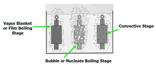
The Three Phases of Quenching

As a brief reminder, let’s revisit the three distinct stages of cooling (Figure 1). The first stage, the “vapor blanket” (or “film boiling”) stage, is characterized by the Leidenfrost phenomenon, which is the formation of an unbroken vapor blanket that surrounds and insulates the work piece. It forms when the supply of heat from the surface of the part exceeds the amount of heat that can be carried away by the cooling medium.

The stability of the vapor layer, and thus the ability of the oil to harden steel, is dependent on: the metal’s surface irregularities; oxides present; surface-wetting additives, which accelerate the breakdown and destabilize the vapor blanket; and the quench oil’s molecular composition, including the presence of more volatile oil degradation by-products (Herring 2015). In this stage, the cooling rate is relatively slow in that the vapor envelope acts as an insulator, and cooling is a function of conduction through the vapor envelope.

The second stage, the “vapor transport” (or “nucleate boiling” or “bubble boiling”) stage, is where the highest heat transfer rates are produced — and where the greatest amount of distortion occurs. The point at which this transition occurs and the rate of heat transfer in this region depend on the oil’s overall composition (base oil, speed accelerators, and antioxidant package). It begins when the surface temperature of the part has cooled enough so that the vapor envelope formed in the first stage collapses. Violent boiling of the quenching liquid results, and heat is removed from the metal at a very rapid rate, largely due to heat of vaporization. The boiling point of the quenchant determines the conclusion of this stage. Size and shape of the vapor (bubbles) are important in controlling the duration of this stage.

Figure 1. The three stages of liquid quenching | Image Credit: The Heat Treat Doctor®

The third stage of cooling is called the “convection” (or “liquid”) cooling stage. The cooling rate during this stage is slower than that developed in the second stage and is exponentially dependent on the oil’s viscosity, which will vary with the degree of oil decomposition. Heat transfer rates increase with lower viscosities and decrease with increasing viscosity. This final stage begins when the temperature of the metal surface is reduced to the boiling point (or boiling range) of the quenching liquid.

The Answer

A sage veteran once reminded the Doctor that we cannot control distortion, only manage it.

As we know, if we were able to control the heat transfer during the nucleate boiling phase, the result would be less gear distortion, especially when the geometry (in this case thin wall, large diameter gears) makes it even more challenging.

What many people do not realize is that in addition to the correct choice of oil, oil temperature, the proper size and design of the quench system (which is fixed for all part or load configurations), and the uniform removal of the vapor blanket in the first stage of quenching influences the development and type of heat transfer that will occur in the nucleate boiling phase — yes, it is uncontrolled, but it can be influenced.

A delay in the start of agitation ensures the vapor blanket phase is extended and (in a sense) more uniformly conforms to the part geometry than it would otherwise. The result is that it is easier to be uniformly swept away once the agitation begins. Interestingly, the vapor blanket begins to form within the first few seconds of quenching and begins to collapse (often in a nonuniform way) as the surface temperature drops. Agitation delay times ranging from 1 to 2 minutes have been used in industry, which are primarily a function of material, (gear) geometry, and tooth profile/thickness.

As to the other question, some manufacturers recommend quenching into slowly agitated oil (100–125 rpm) — the slower agitation only intended to push any moisture molecules around, then increasing the speed to normal agitation rates once the load is fully submerged. Appropriate safety precautions must be followed with either method. A great deal of success has been reported using this method for many of the same reasons as above.

On another note, there is some merit in vacuum oil quenching to vary the pressure over the oil. Interestingly, the characteristics (i.e., size and distribution) of the “bubbles” formed in the nucleate boiling phase changes and the end result is that they can be more easily and more uniformly swept away.

In Summary

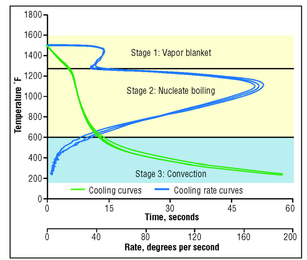
A word or two is in order about measuring and maintaining the quench oil. Measuring the efficiency (i.e., speed) of an oil can be done in one of two ways. The first method is by measuring the oil’s cooling ability (i.e., hardening power). Since cooling ability is independent of steel selection (composition and grain size) this method is popular since it provides information about the oil itself independent of its end use application (Figure 2).

Figure 2. Typical cooling curves and cooling-rate curves for new oils | Image Credit: The Heat Treat Doctor®
Table A. Classification of Quench Oils

The older GM Quench-O-Meter method (Table A) can be used as well.

Variables Affecting Dimensional Change

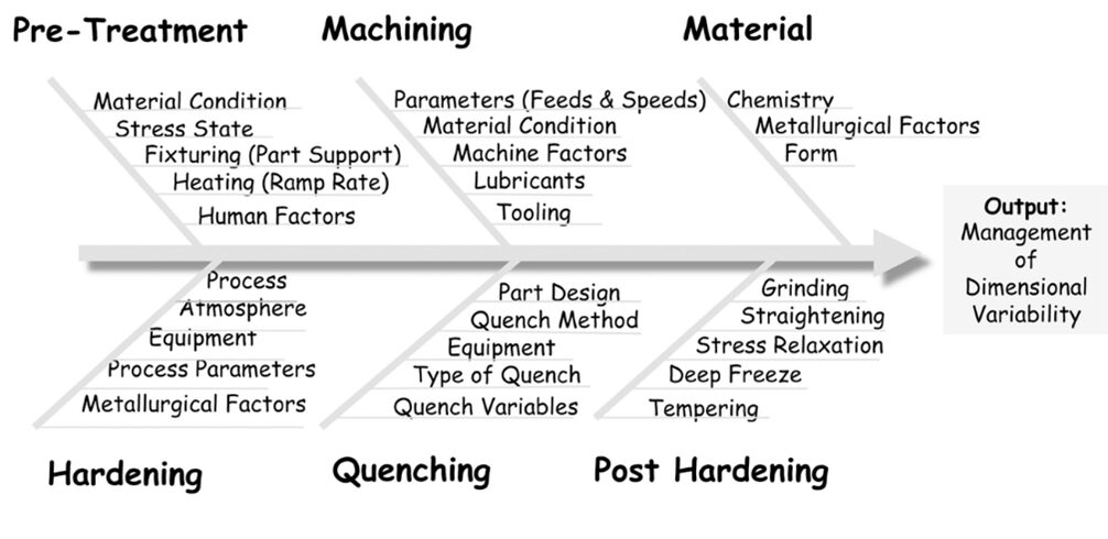
A number of factors influence post-heat treat distortion, including those related to material, manufacturing, and heat treating (Figure 3).

Figure 3. Distortion (Ishikawa) diagram | Image Credit: The Heat Treat Doctor®

When selecting an oil quench process, some of the many factors to consider include:

  • Material — form, chemistry, hardenability, grain size, homogeneity, cleanliness, microstructure
  • Heat treatments performed at the mill
  • Starting microstructure — mill or third-party heat treating prior to manufacturing
  • Manufacturing process — sequence of operations, tooling, speeds & feeds
  • Part orientation during manufacturing, as opposed to grain orientation
  • Grids, baskets, and fixtures — both material & design
  • Load configuration — part spacing, orientation, arrangement (load density)
  • Load weight (gross or net)
  • Maximum quench fixture size, weight, shape
  • Part geometry and mass — maximum/minimum part section thickness, consideration for whether the component part is uniform in thickness or has thin and thick sections next to one another
  • Residual stress state before heat treatment
  • Targeted hardness range (initial or final)
  • Type of process being run (e.g., hardening, case hardening)
  • Free quenching or restricted (press or roll) quenching
  • Oil type — quenching characteristics, cooling curve data
  • Oil speed, condition, viscosity (fast, 7–9 second oil; medium, 10–14 second oil; slow, 15–18 second oil; or marquench, >20 second oil)
  • Oil temperature (initial, instantaneous rate of rise, recovery time to initial temperature)
  • (Effective) quench tank volume
  • Height of oil above the load
  • Agitation — agitators or pumps
  • Quench tank design factors
    • Agitation method and number of agitators or pumps
    • Type of quench tank baffling
    • Location/size of agitators or pumps
    • Type of agitators (e.g., fixed, two speed, variable)
    • Propeller size (e.g., diameter, clearance in draft tube)
    • Internal tank baffling (e.g., draft tubes, directional flow vanes)
    • Flow direction
    • Flow restrictions (quench elevator and baffling design)
    • Volume of oil
    • Maximum (design) temperature rise
    • Heat exchanger-type, size, heat removal rate (instantaneous and total demand)
    • Quench elevator design (e.g., hearth type, sidewalls, flow restrictions)
  • Flow velocity (with and without a load present)
  • Number of furnaces to be served by the quench system
  • Duty cycle (i.e., the frequency of quenching or time between quenches)
  • Post heat treatment operations, if applicable
  • Furnace temperature uniformity
  • Furnace repeatability
  • Type of furnace atmosphere
  • Post processing (e.g., washing, deep freeze or cryogenic treatment, number of tempers)
  • Time delay between heat treat operations (especially important for high hardenability materials to avoid cracking)

References

Herring, Daniel H. 2015. Atmosphere Heat Treatment. Volume 2, BNP Media II.

About the Author

Dan Herring
“The Heat Treat Doctor”
The HERRING GROUP, Inc.

Dan Herring has been in the industry for over 50 years and has gained vast experience in fields that include materials science, engineering, metallurgy, new product research, and many other areas. He is the author of six books and over 700 technical articles.

For more information: Contact Dan at dherring@heat-treat-doctor.com.

For more information about Dan’s books: see his page at the Heat Treat Store.


Ask The Heat Treat Doctor®: What Oil Quenching “Tricks” Help Manage Distortion? Read More »
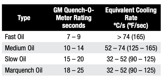
Improve Vacuum Quench, Maximize Tool Life

Vacuum furnaces performing hardening have been in use for over 50 years, yet many heat treaters may not be taking full advantage of newer, more advanced analysis tools and methods. Controlling the cooling pressure can dramatically improve toughness and tool life, but only if applied with precision. In this Technical Tuesday installment, Paulo Duarte, technical director at Treatnorte, explores the science behind gas quenching, the role of step cooling, and why measuring and adjusting cooling curves is critical for consistent, high-performance results.

This informative piece was first released in Heat Treat Today’s March 2026 Annual Aerospace Heat Treating print edition.


Introduction

It has been a long time since the invention of the vacuum hardening process, yet innovation in this field continues. In recent years, industrial furnaces capable of operating with higher cooling gas pressures — up to 15 bar now commonly offered on the market — have become standard. But do we truly know how to make the best use of such high pressures?

Pressures up to 10 bar were first applied to cool small parts made from cold-work tool steels, such as sheet metal stamping tools. However, such high pressures can lead to cracking in larger hot-work steel dies when cooled directly. Step cooling was introduced as a solution: start with a fast initial cooling at higher temperatures to avoid carbide formation, then gradually lower pressure stages during the final cooling phase to reduce distortion and minimize the risk of crack appearance.

Despite this empirical knowledge, the question remains: do we really understand what we are doing? Are we routinely measuring cooling rates to determine where they stand on the CCT diagram, predicting microstructure and properties, and adjusting quenching parameters accordingly? And are we certain about which pressures to use for producing high-performance, demanding tools?

Cooling in Vacuum Furnaces

Quenching is one of the most critical steps in the hardening cycle. It transforms austenite into the optimal final microstructure, avoiding the formation of coarse carbides and pearlitic constituents during cooling. This ensures the finest possible microstructure.

Figure 1. Gas quenching in a vacuum hardening furnace | Image Credit: SECO/WARWICK
Figure 2. Surface cooling rates region on systematic analysis of parts quenching in a 600 mm x 600 mm x 900 mm furnace. Parts comprising weights from 500 up to 1,000 kg. Cooling pressures varies from 4 to 5 bar. Hot work tool steel. | Image Credit: Metaltec Solutions

In vacuum furnaces, this is typically achieved by injecting cooling gas through nozzles directed at the surface of the parts located in the furnace hot zone. During cooling, the gas circulates through the chamber, being drawn through furnace ports into contact with the heat exchanger tubes. A turbine then blows the cooled gas back into the hot zone where the load is located (Figure 1).

The higher the programmed cooling pressure, the greater the volume of gas passing through the nozzles over the same period of time. This increases the heat transfer from the parts to the cooling gas, resulting in a faster cooling rate.

By measuring successive cooling curves for different loads, specifically for single hot-work steel tools weighing over 500 kg, surface cooling rates pass through the bainitic–martensitic domain (the green area of the CCT diagram shown in Figure 2). Thinner parts tend to cool closer to the martensitic end at the Ms-Bs intersection, while larger tools tend to approach the pearlitic nose.

These observations highlight the importance of adjusting cooling pressure to produce the desired microstructure and account for the different cooling behaviors of large, medium, and small parts.

Investigative Approach: Testing Furnace Data Against CCT Diagrams

Measuring part temperatures during cooling began over 20 years ago, using thermocouples and data loggers, and comparing the results to steel continuous cooling transformation (CCT) diagrams. Most vacuum furnaces do not include this capability as standard, and when available as optional software, many companies choose not to invest in it. In 2005, it was discovered what few in the industry knew at the time: hardening hot-work tool steels in industrial vacuum furnaces often results in a bainitic–martensitic microstructure. This phenomenon is now more widely recognized, with published cooling curves overlaid on CCT diagrams for larger tools becoming more available.

Even so, open discussion remains rare, partly because many heat treaters are reluctant to present this evidence to academia, fearing criticism that their results do not match the fully martensitic microstructure taught at universities. This is not a debate about right or wrong, but rather an opportunity for research and improvement in heat treatment practices worldwide.

After initial testing with a 600 mm × 600 mm × 900 mm French-made single-chamber furnace, trials continued with a larger 900 mm × 900 mm × 1,800 mm German-made vacuum furnace. These tests began by measuring both surface and core temperatures for repeated cycles with small and large charges ranging from small cold-work tools to hot-work tool steel parts weighing 500–1,500 kg. Leading vacuum furnace manufacturers in North America and Europe have developed technologies capable of successfully heat treating small, medium, and large tools, resulting in microstructures that often contain both bainite and martensite. This is, in fact, an inherent characteristic of the technology. Such tools have performed well in service for decades. That said, heat treaters using higher cooling pressures have seen improved tool life significantly, while also increasing the risk of treatment failures if the pressure is too high.

In the last 10 years, properties and microstructure analyses have shown that variations in cooling rate can significantly change the microstructure and toughness of the part even within the same bainitic–martensitic domain of the CCT diagram.

With the emergence of Industry 4.0 and 5.0, along with digitalization and AI, systematic research into heat treatment processes combined with quenching deformation simulation can lead to better selection of cooling pressures. This is a critical parameter in controlling the hardening process, and it has a direct impact on part toughness and service performance. Metaltec Solutions introduced one of the first software tools aimed at improving vacuum heat treatment through Industry 4.0 concepts in 2017. This technology represents a step toward greater awareness and precision in tool steel hardening, helping heat treaters program their cycles for optimal performance in demanding applications.

Regulating Pressure in Vacuum Hardening Furnaces

To obtain the best possible microstructures, gas quenching must be programmed in the furnace so that the cooling rate is kept as close as possible to the martensitic end, i.e., at the Ms-Bs intersection, of the CCT diagram, avoiding the formation of coarse and undesirable microconstituents in the steel. This is achieved by selecting the highest permissible cooling pressure that still prevents cracking or excessive deformation. While small parts can withstand direct high-pressure cooling, larger tools require a reduction in cooling pressure.

Preliminary Pressure Comparison

For optimal quenching of large parts, the cooling pressure should not remain constant throughout the entire cooling cycle. Instead, high pressure should be applied during the initial cooling stage to prevent coarse carbides and pearlite formation and then reduced when the surface temperature reaches approximately 550°C (1022°F). This creates a martempering stage at lower pressures, reducing the risk of distortion and cracking.

Figure 3a. Cooling pressure effect on Vidar Superior (an H11 steel grade
variation) part surface toughness | Image Credit: Metaltec Solutions
Figure 3b. Cooling pressure effect on 400 mm x 400 mm x 400 mm
block surface toughness | Image Credit: Metaltec Solutions

If we measure the toughness of steel pieces quenched at different cooling pressures, then tempered together to achieve a typical 46–48 HRC hardness (in hot work tool steel), we find that higher cooling pressures result in greater toughness. Using older furnace pressures (around 3 bar) yields lower toughness, whereas increasing cooling pressure can improve toughness by approximately 60% (Figure 3a). This translates into longer tool life, since high-pressure-quenched tools better absorb stress, delaying the initiation and propagation of cracks. These benefits result from higher cooling rates (Figure 3b) and the corresponding finer microstructures achieved.

Although quenching at 3, 6, and 9 bar passes through the same transformation domain on the CCT curve, differences in the resulting internal steel structure, whether coarser or finer, are clearly observable.

True Toughness and Speed

Looking in more detail at the above findings, we can observe that when parts are cooled in a 900 mm × 900 mm × 1,800 mm vacuum furnace, the gas temperature drops below the Ms temperature (for typical hot work tool steels) in less than one minute. The gas temperature then remains near room temperature during the subsequent cooling of the parts (Figure 4a).

Figure 4a. Cooling NADCA block in a large vacuum hardening furnace; gas cooling rate according to gas pressure used | Image Credit: Metaltec Solutions
Figure 4b. Cooling NADCA block in a large vacuum hardening furnace; surface cooling curves and its respective toughness after tempering, with the alteration of the cooling curve behavior provided by the martempering (final hardness level 46–48HRC hot work tool steel | Image Credit: Metaltec Solutions

The parts, however, take considerably longer to cool down to the furnace unloading temperature, depending on the cooling pressure applied. When analyzing the cooling of large dies using the NADCA block as the standard size for comparison, the surface cooling curves vary according to the applied pressure, falling into the bainitic–martensitic domain for 3, 6, and 9 bar cooling pressures.

From this data, it can be seen that hardness is not significantly affected by using 3, 6, or 9 bar cooling pressures, even though the higher pressures produce cooling rates up to twice as fast as the slower ones. Toughness, however, is largely influenced by the way the cooling curves pass through the bainitic–martensitic domain, whether crossing the Bs and Ms intersection closer to the martensitic end (9 bar), near the center (6 bar), or closer to the pearlitic nose (3 bar).

Tuning Pressure and Time

These results show that, within the typical cooling rates of vacuum hardening (Figure 2), toughness varies significantly with cooling pressure, corresponding to finely tuned cooling speeds ranging from approximately 9 to 16°C/min (48 to 61°F/min) between 800°C and 500°C (932°F and 1472°F). This highlights the need to use the highest possible cooling pressures to achieve excellent properties while avoiding direct high-pressure cooling of large parts by applying step cooling with an initial fast cooling phase, followed by reduced pressure.

How Microstructure Drives Toughness

The reason for achieving better properties at higher cooling pressures lies in the resulting microstructure, as shown in Figure 5. Fine bainite and martensitic needles, formed through faster cooling rates, are responsible for the higher toughness observed. When lower cooling pressures are used, the cooling rate decreases, leading to coarser needle sizes (Figres 5a–c) and, consequently, lower toughness values.


Figure 5a-c. Microstructures obtained after quenching Orvar Supreme (premium H13 steel): a) 100°C/min; b) 12°C/min; c) 3°C/min (or, a) 180°F/min; b) 22°F/min; c) 5°F/min) | Image Credit: Metaltec Solutions
Figure 6. Toughness model | Image Credit: Metaltec Solutions

This can be explained by Figure 6. In a coarser microstructure, cracks can propagate more easily because there are fewer obstacles to their advance. In finer microstructures, the higher density of needles forces cracks to deviate repeatedly from their path due to the branching effect, altering the directions of crack propagation. This “shock absorber” effect — caused by the frequent detours a crack experiences when traveling through a greater number of fine needles — is the reason for the toughness improvement observed when higher cooling pressures are used to achieve faster cooling rates.


Figure 7. Convection coefficients for a 900 mm × 900 mm × 1,800 mm vacuum hardening furnace according to the pressure being used | Image Credit: Metaltec Solutions

Each furnace behaves differently, from one furnace builder to another and also depending on the level of maintenance of a furnace. So a similar furnace to the one used for obtaining cooling curves and corresponding toughness values (Figure 4b) was used to obtain the convection coefficients (Figure 7). We can see a strong correlation between convection coefficient, pressure, and final toughness obtained, indicating that these features must be carefully adjusted to reach optimal part properties and longer service life.

Conclusion

Properly applying cooling pressures, through direct high-pressure cooling for small loads or step cooling for larger tools, can significantly increase part toughness and extend tool life. The key lies in understanding how cooling curves interact with the bainitic–martensitic microstructure and adjusting pressure according to part size, geometry, and furnace characteristics.

By measuring temperatures, analyzing microstructures, and fine-tuning cooling cycles, heat treat operators can achieve consistent, high-performance results, as demonstrated with the above studies on tool steels. Faster, well-controlled cooling typically produces finer bainitic–martensitic microstructures which results in a part with “shock absorber” qualities.

Ultimately, maximizing cooling pressure, not just for minimal distortion, creates more durable tools, reduces downtime, and strengthens competitiveness through part performance.

About The Author:

Paulo Duarte
Technical Director
Treatnorte

Paulo Duarte is an independent researcher and consultant on heat treat technologies, also working as technical director at Treatnorte. His education and expertise in metallurgy have culminated in several articles and patents. Previously, he was the project manager at Metalsolvus and also had been the technical manager and heat treatment manager within bohler-uddeholm group for the Portuguese market. Currently, Paulo focuses on helping heat treaters by providing innovative, more efficient, and profitable heat treatment services to companies.

For more information: Contact Paulo Duarte at pauloduarte@treatnote.pt.

Improve Vacuum Quench, Maximize Tool Life Read More »