10 pasos para solucionar las fallas en un equipo de inducción
![]()
 Nikola Tesla afirmó: <<Si quieres descubrir los secretos del universo, concéntrate en la energía, la frecuencia y la vibración.>>
Al revisar los mecanismos internos de un sistema de inducción es posible evidenciar cada uno de estos tres elementos. Los 10 pasos de esta guía servirán para apoyar a los operadores de departamentos internos de tratamiento térmico en entender los secretos de la inducción para así identificar posibles escollos en tales sistemas y dar solución a problemas comunes que se puedan presentar.
This original content article was first written by Alberto Ramirez, engineer of Power Supply and Automation at Contour Hardening, Inc. and an honoree from Heat Treat Today’s 40 Under 40 Class of 2021, for Heat Treat Today's May 2023 Sustainable Heat Treat Technologies print edition. Read the Spanish version below, or click the flag above right for the English version.
Puedes hacerlos llegar a Bethany Leone al correo bethany@heattreattoday.com

Power Supply and Automation Engineer
Contour Hardening, Inc.

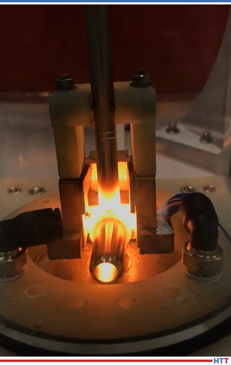
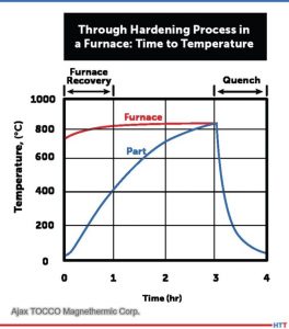
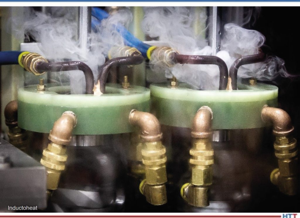
Los metales pueden calentarse mediante el proceso de inducción electromagnética, mediante el cual un campo magnético alternativo cerca de la superficie de una pieza de trabajo metálica (o conductora de electricidad) induce corrientes de Eddy (y, por lo tanto, calentamiento) dentro de la pieza de trabajo.
Los sistemas de inducción pueden llegar a ser sistemas complejos que tienen como objetivo endurecer piezas o secciones específicas de un componente mecánico, dependiendo del grado de complejidad de la pieza a tratar; para el profesional, el desafío será el diagnóstico de los problemas que se lleguen a presentar.
1. Familiarízate con el proceso
Source: Contour Hardening, Inc.
El proceso de inducción envuelve muchas características tales como: posición de la pieza dentro de la bobina de inducción, posiciones de carga, posiciones de enfriamiento, tiempos de ciclo, potencia eléctrica aplicada, entre otras. Es importante que el profesional sea capaz de identificar la falla y la situación particular en el momento en el que se está presentando.
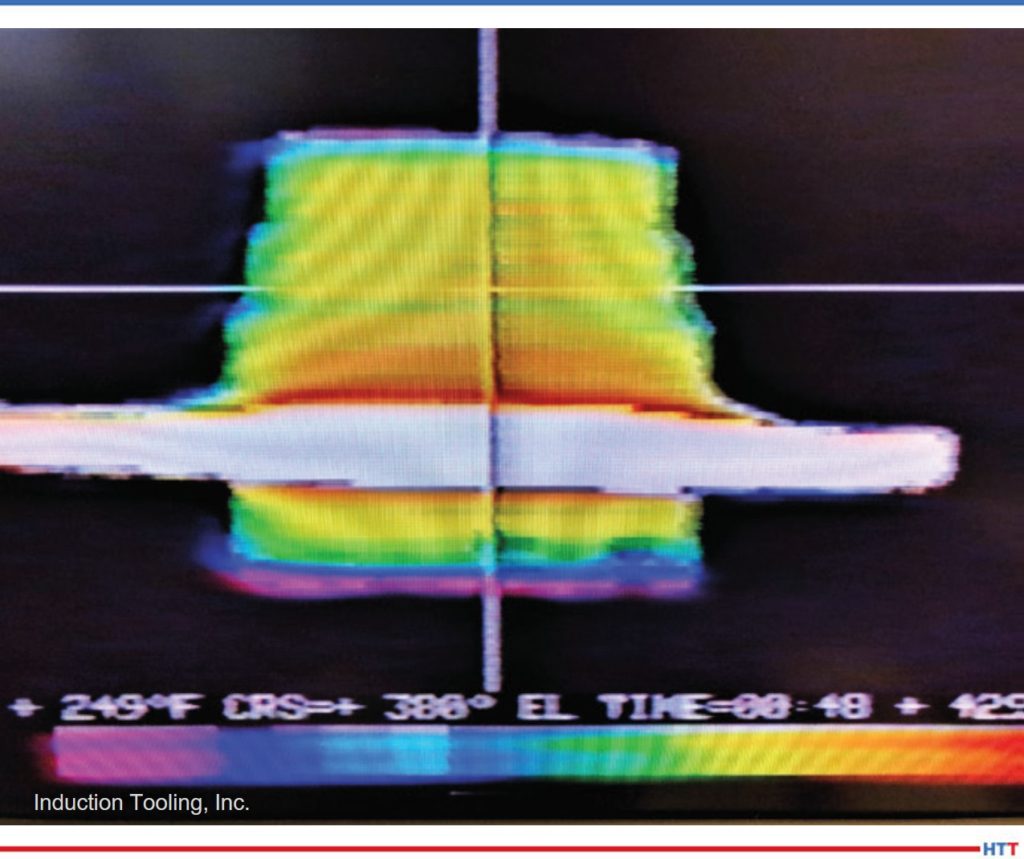
En algunas ocasiones las fallas no son evidentes y, por ende, es indispensable analizar la pieza que ha sido tratada; este análisis puede ser clave para entender situaciones tales como: falta de profundidad de capa por potencia eléctrica o disminución en la frecuencia de salida, entre otros posibles escenarios.
Adicional al análisis de la pieza, es vital inspeccionar la “escena del crimen” ya que muchos de los sistemas de inducción, dada la naturaleza del proceso y el peligro que implica manejar altos potenciales eléctricos, suelen ser en extremo automatizados y las estaciones de trabajo de difícil acceso para el personal, así que una buena estrategia de trabajo consiste en observar detenidamente las condiciones generales del equipo para determinar el punto de inicio para la resolución del problema.
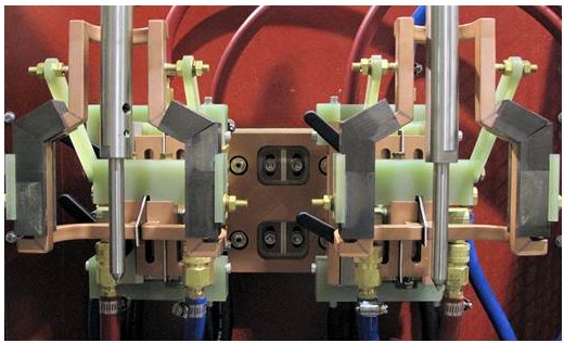
2. Identifica los componentes principales de tu sistema de inducción, así como los mecanismos de seguridad para ciertas zonas en particular
Entender la interrelación del sistema es importante para comprender qué elemento realiza cierta acción, así como los canales de comunicación entre ellos. Una vez que se genere este conocimiento, se puede asociar una falla a un componente en particular. Usualmente los sistemas de inducción se componen de los siguientes elementos:
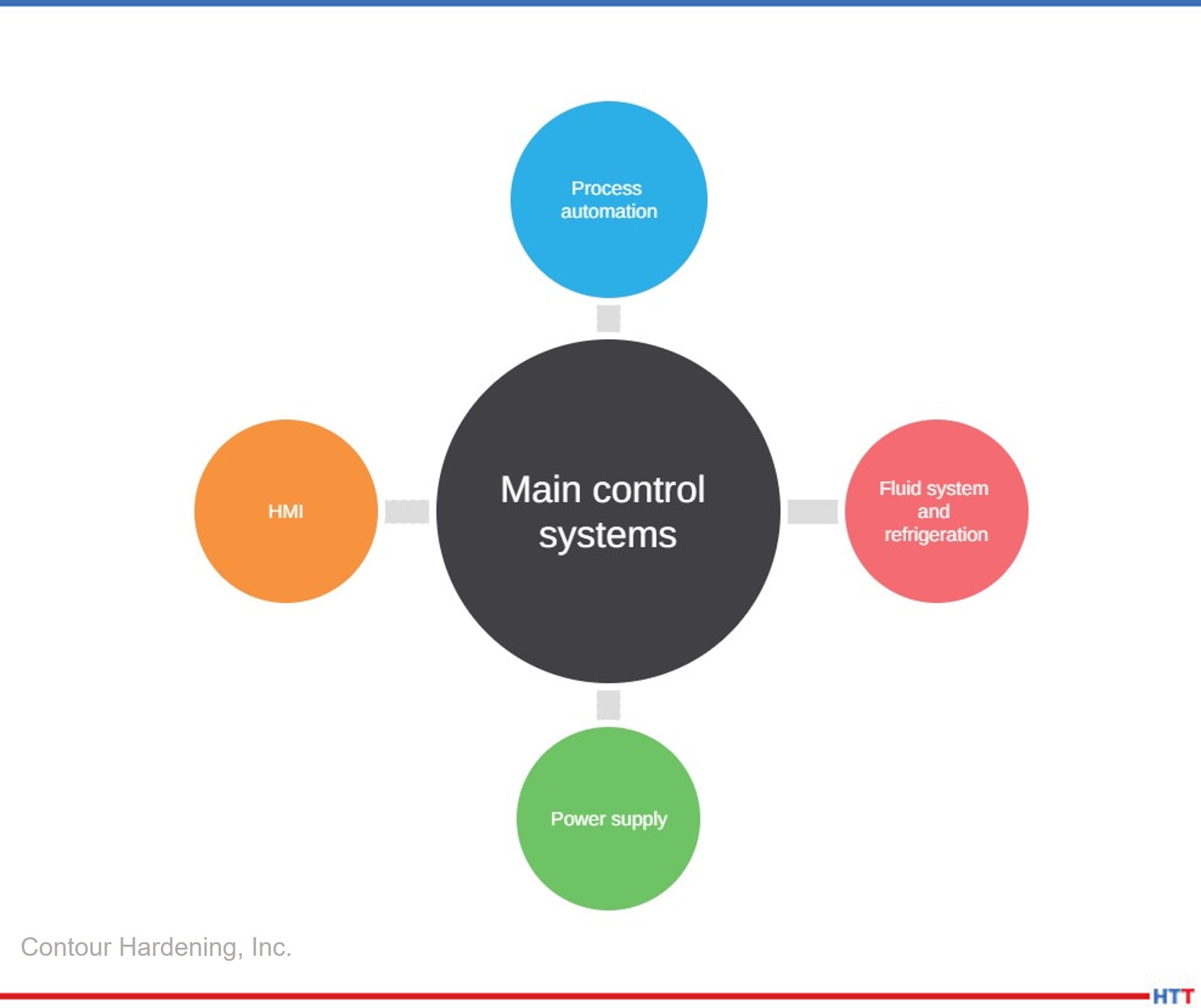
Source: Contour Hardening, Inc.
Como mencionamos con anterioridad el proceso implica altos potenciales eléctricos, y para eso la naturaleza de las fuentes de alimentación involucra dispositivos electrónicos de potencia, como capacitores eléctricos, los cuales almacenan energía y, por ende, es importante descargar eléctricamente el sistema antes de comenzar a inspeccionar un equipo.
3. Ten preparadas las herramientas necesarias para realizar un buen análisis del problema
Source: Contour Hardening, Inc.
Al igual que cualquier problem técnico, el uso de la herramienta mecánica es indispensable al realizar algún tipo de proyecto, pero para el diagnóstico de una falla en un equipo de inducción es importante contar con:
- Osciloscopio
- Generador de funciones
- Amperímetro
- Multímetro digital y analógico.
- Sondas de alto voltaje
Sin estos elementos es muy difícil llegar a un diagnóstico fiable, y la posibilidad de encontrar la falla es mínima. Por ende, tener estos medidores en buen estado y, sobre todo, calibrados nos da una perspectiva más clara del problema.
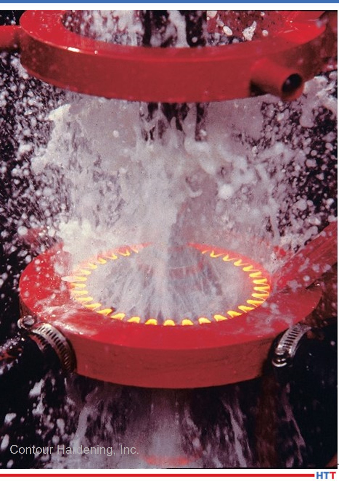
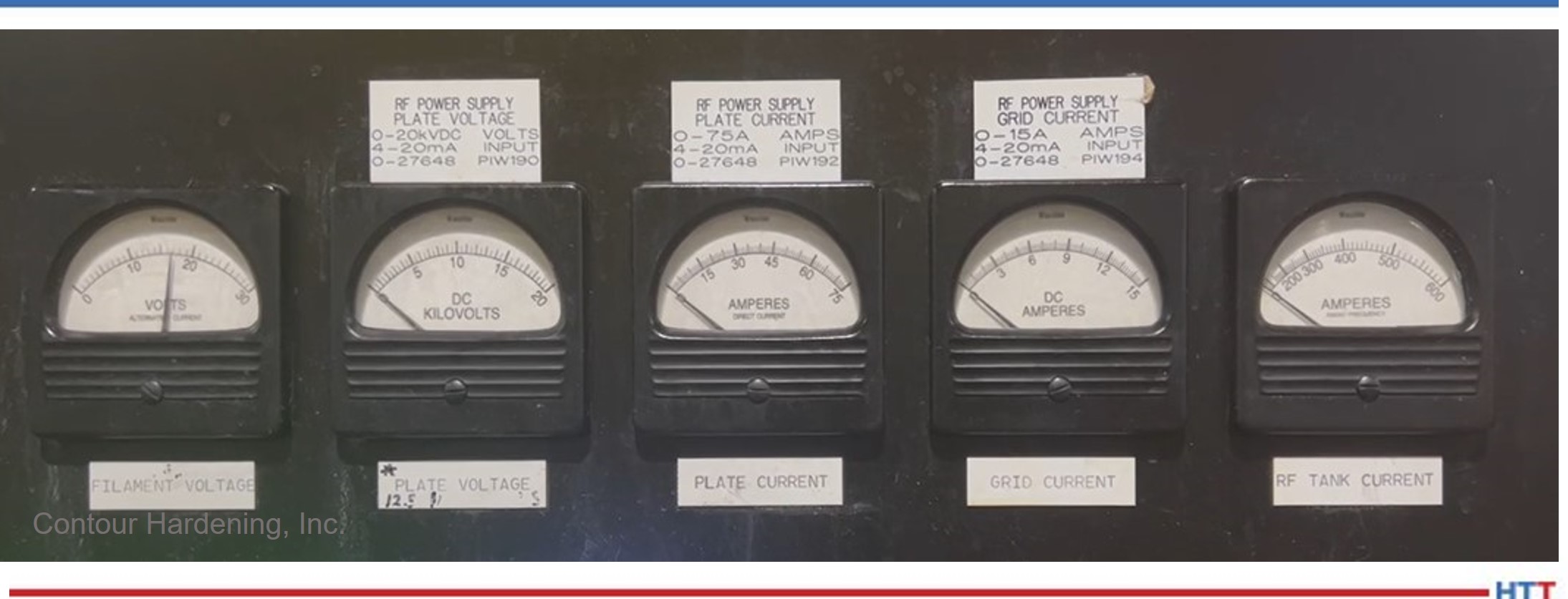
4. Verifica que los sensores del proceso, los monitores de energía y las bobinas de inducción funcionen correctamente
Existen distintos medidores que recogen información acerca del proceso; esta información en su mayoría puede ser visualizada a través del HMI (Human Machine Interface), y, en muchas ocasiones, una buena manera de comenzar a entender el problema es recopilar la información del proceso. Si los medidores no funcionan correctamente, te pueden llevar a conclusiones erróneas.
Verifica que los medidores de energía estén funcionando correctamente, así como tus señales de entrada y de salida.
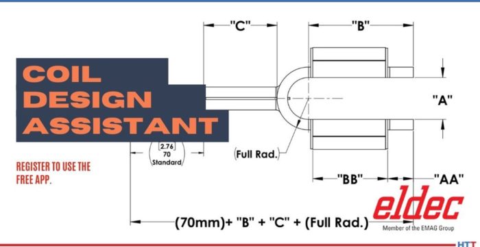
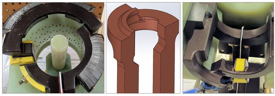
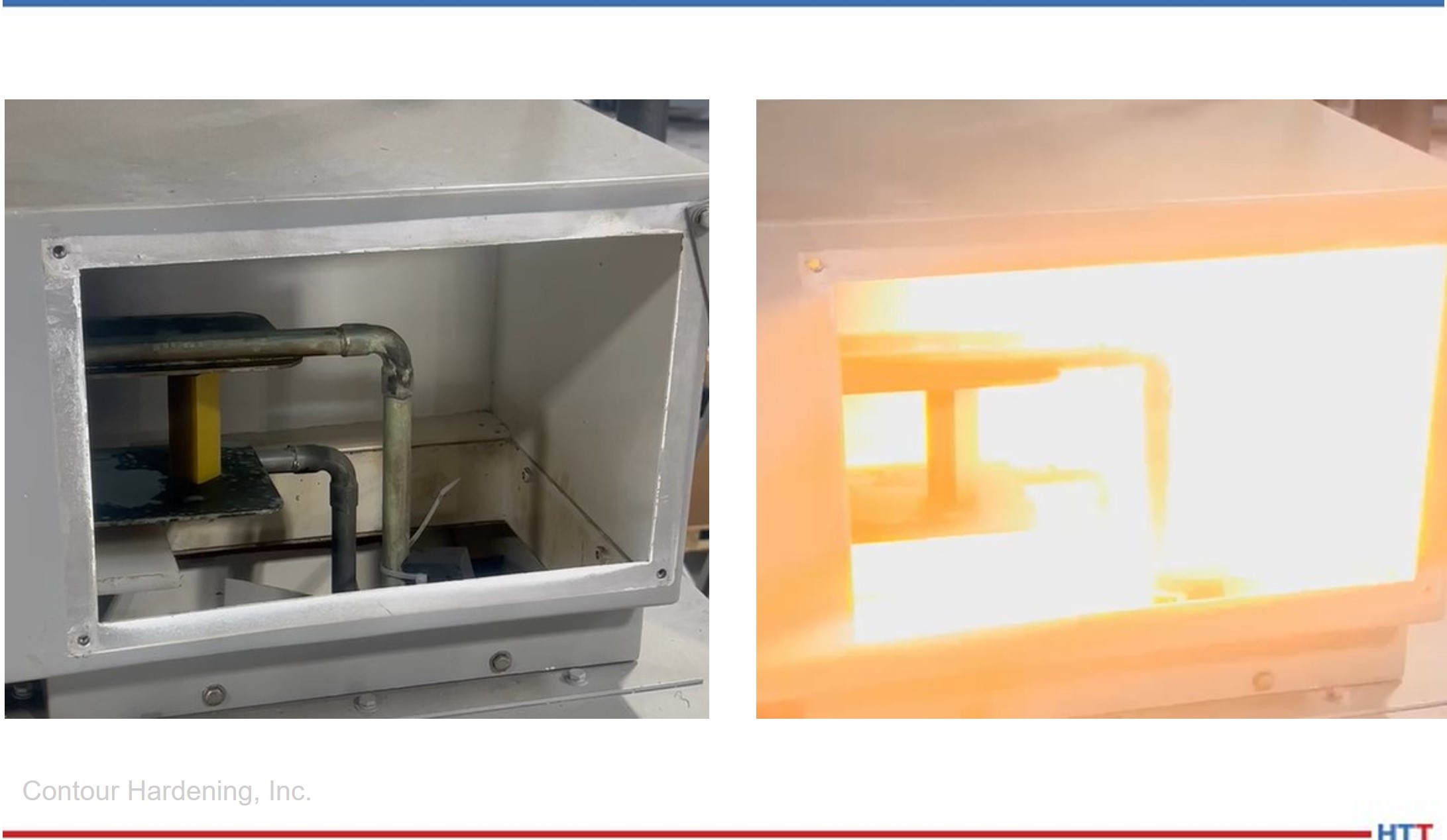
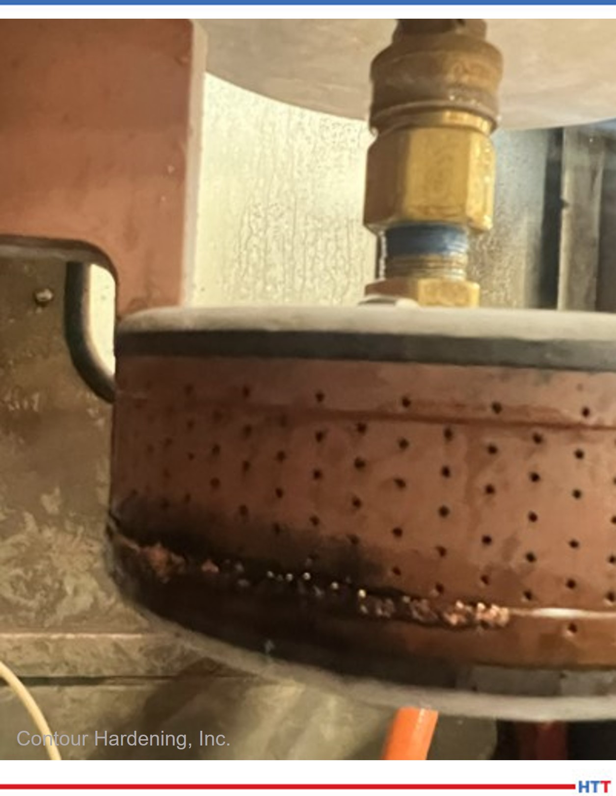
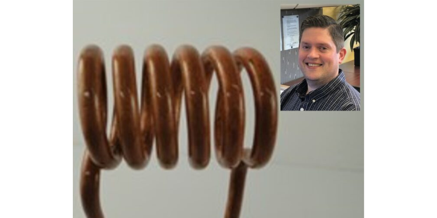
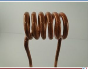
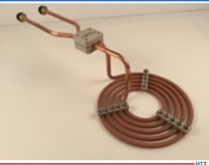
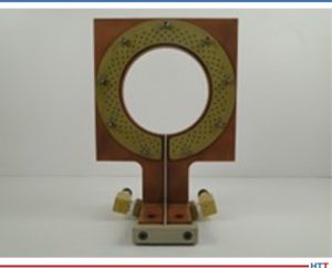
Las bobinas de inducción son un elemento clave en el proceso de inducción ya que acorde a su geometría generan los campos magnéticos adecuados para lograr los resultados metalúrgicos esperados. Si existen fugas de agua o los elementos de transmisión eléctrica se encuentran sueltos o sucios, seguramente podrán ser la raíz del problema. Es importante comenzar a realizar el diagnóstico de la falla una vez se haya descartado este circuito en particular.
Source: Contour Hardening, Inc.
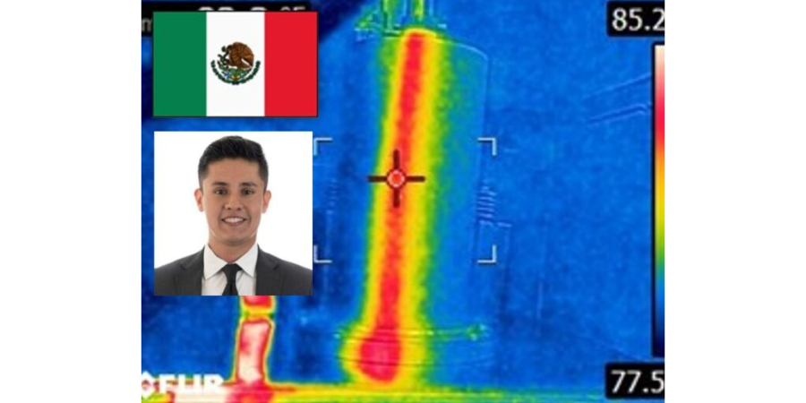
5. Realiza estudios de energía constante en tu subestación para identificar posibles problemas en tu suministro de energía, así como tiempos críticos
La energía eléctrica es la fuente principal en un proceso de inducción; las fuentes de alimentación transforman y potencializan este recurso para crear campos electrónicos lo suficientemente fuertes para generar el calor en la pieza.
Por ende, es importante descartar con evidencia que el problema en cual nos encontramos no se debe a una falla del sistema eléctrico del cual nuestro sistema de inducción forma parte. De igual manera entender cómo se comporta nuestro sistema eléctrico nos puede ayudar a generar patrones de comportamiento que puedan determinar la solución en momentos específicos en los que se lleguen a presentar.
6. Trabaja de forma metódica documentando tus movimientos y realiza un paso a la vez
Los sistemas de inducción pueden ser muy intimidantes si no has tenido experiencia previa, y, al igual que con cualquier elemento o situación, es importante abordar de manera lógica el problema analizando el modo de la falla, identificando las partes principales que interactúan en ese preciso momento, y, a partir de este análisis, documentar y realizar pequeños pasos, uno a la vez, ya que, de no ser así, es muy probable que pierdas todo el trabajo realizado y la situación empeore.
Source: Contour Hardening, Inc.
Si los movimientos no son exitosos, siempre puedes regresar a tu punto de partida e intentar otro acercamiento. La idea consiste en que el modo de la falla se mantenga estable sin importar los movimientos realizados hasta que se resuelva el problema. De esta manera lograrás contener la falla; de otra manera podrías estar dañando otros elementos sin darte cuenta.
Es muy importante entender que los procesos son secuencias que anteceden y preceden a nuevos eventos; si entiendes el proceso y, una vez resuelto el problema, ahora tienes una nueva falla, es importante analizar si esta falla es la continuación del proceso ya que, de ser así, es posible que te encuentres frente al caso de un evento que está desencadenado una serie de fallas y se haga necesario practicar un análisis más profundo. La idea general es llegar a la raíz del problema y mitigar el riesgo.
7. Intenta cualquier posibilidad relacionada con el proceso sin importar que la relación entre ésta y el problema no sea directa
Un pensamiento lógico puede resolver la mayoría de las fallas técnicas de un sistema, pero, para fallas excepcionales, es necesario utilizar la imaginación y agotar todos los recursos posibles ya que el área de interés más insignificante o el lugar menos pensado puede ser la clave para resolver un problema.
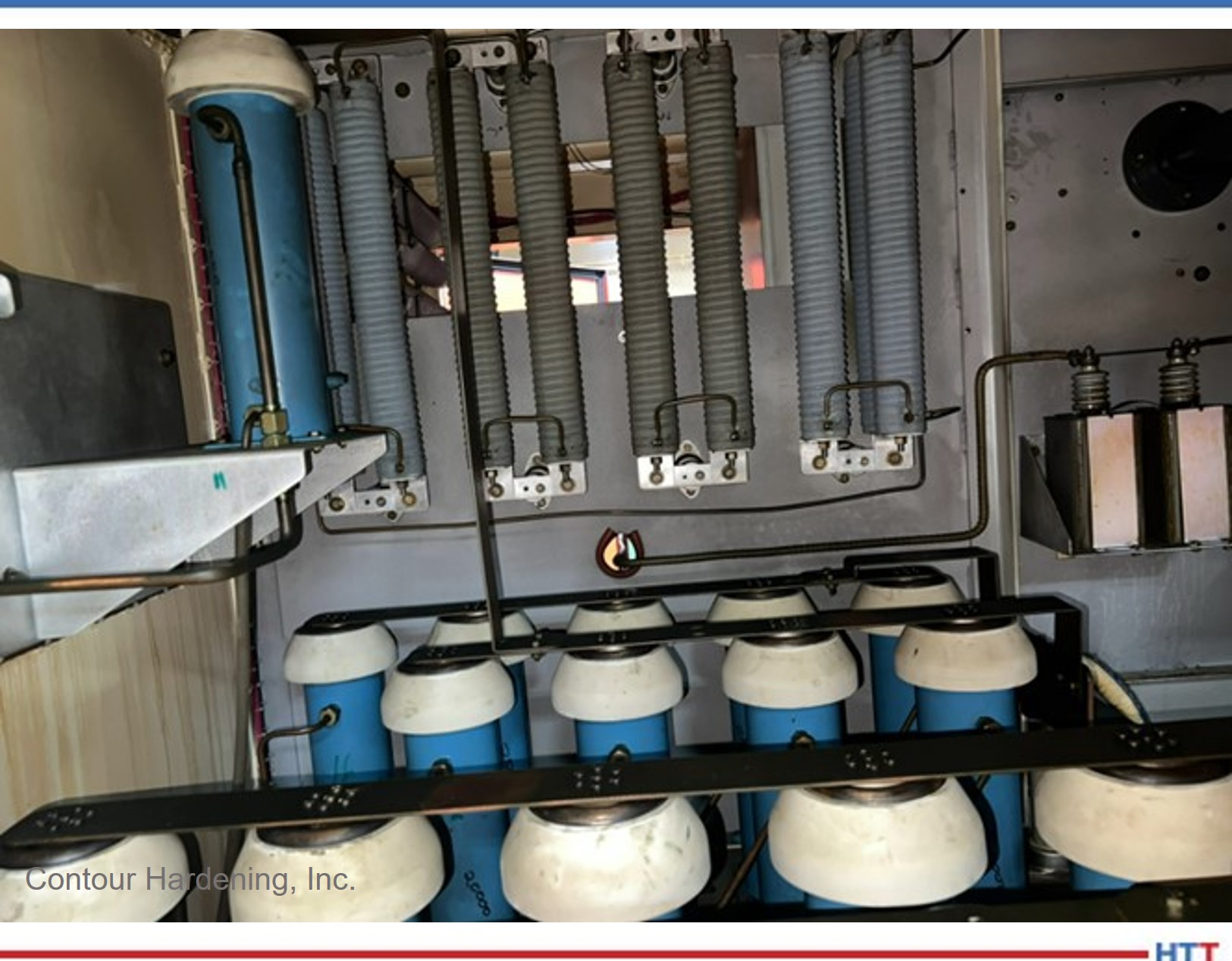
8. Conoce tus fuentes de alimentación
Uno de los factores claves en cualquier equipo de inducción son sus fuentes de alimentación. Las fuentes de alimentación son equipos que no requieren un mantenimiento tan arduo en comparación con otros sistemas en la industria, pero, de no presentarse las condiciones mínimas de mantenimiento, pueden generar altas pérdidas para la organización.
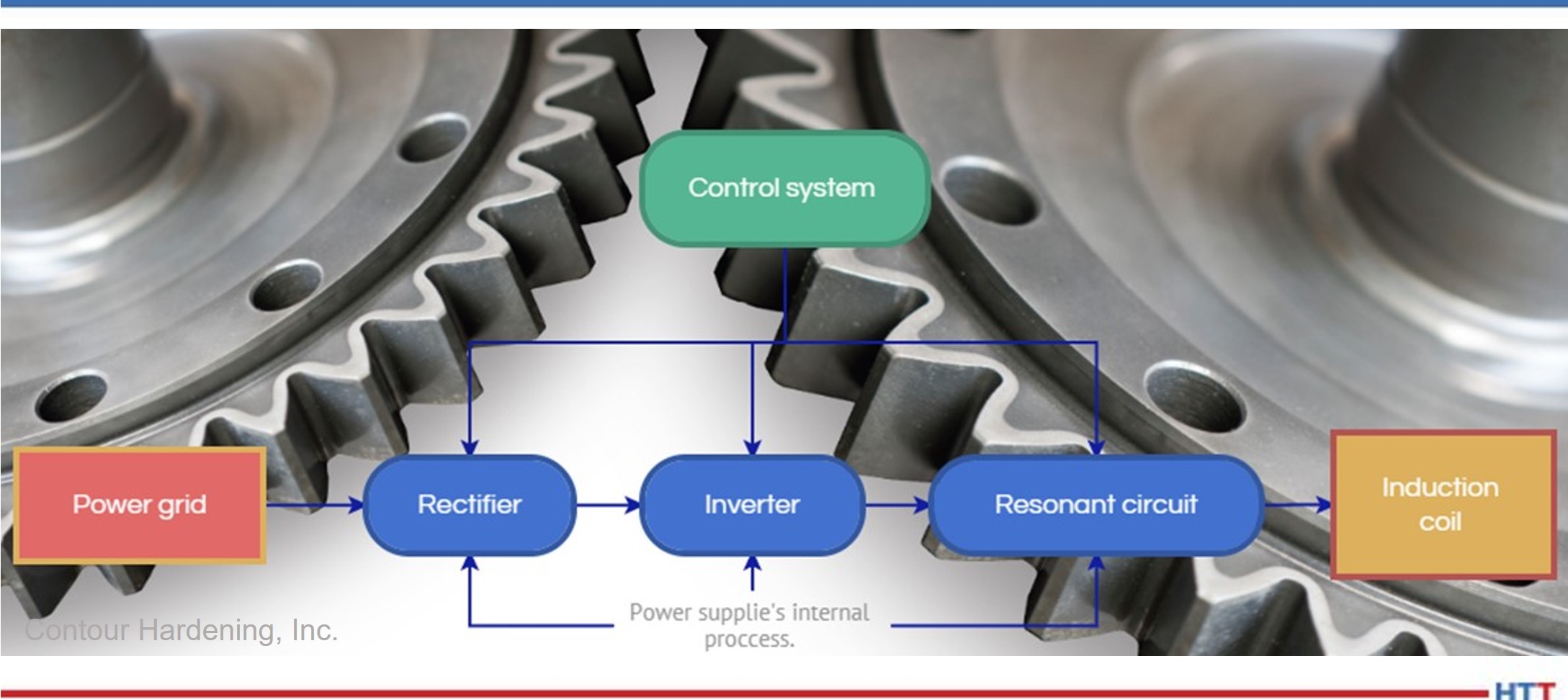
Source: Contour Hardening, Inc.
En los casos en los que el problema se encuentra en las fuentes de alimentación, es vital que se siga el mismo proceso metódico previamente descrito. Entender cómo funciona el proceso de transformación de la energía te dará una ventaja, al igual que conocer los componentes empleados o el tipo de tecnología utilizado en el proceso de rectificación, en la inversión (estado sólido o tubos de electrones) y en el circuito resonante. Generalmente las fuentes de alimentación siguen el siguiente patrón de transformación (Figura 6).
9. Identifica las partes críticas de tu equipo de inducción y prepara un inventario de éstas
Contour Hardening, Inc.
Usualmente los componentes que forman parte de las fuentes de alimentación son difíciles de conseguir dependiendo de la antigüedad de tu equipo, y con la reciente crisis de microchips en el mercado, existen tiempos de entrega muy largos para los elementos de control y automatización; de igual manera, los precios de los mismos se han disparado. Por ende, es vital que exista una lista de partes críticas y un inventario de éstas.
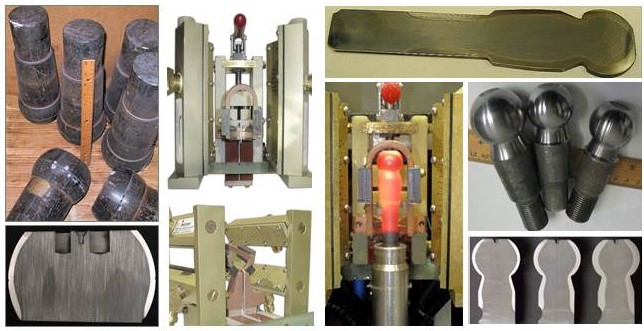
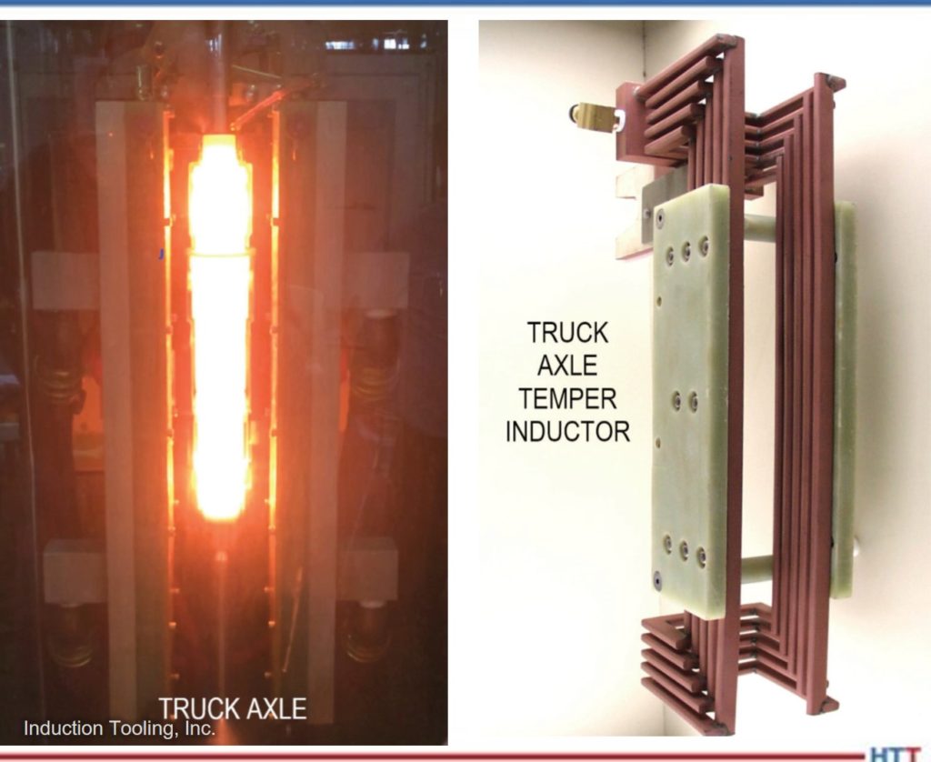
Adicionalmente a los elementos descritos, las bobinas de inducción suelen ser elementos muy característicos e importantes en el proceso de inducción. Éstas bobinas son elementos complejos que han sido diseñados exclusivamente para la pieza, por lo que su fabricación puede tomar varias semanas, y es importante tomar las precauciones necesarias para mantener un movimiento de mantenimiento constante.
10. Realiza mediciones preventivas al sistema para generar un patrón de comportamiento
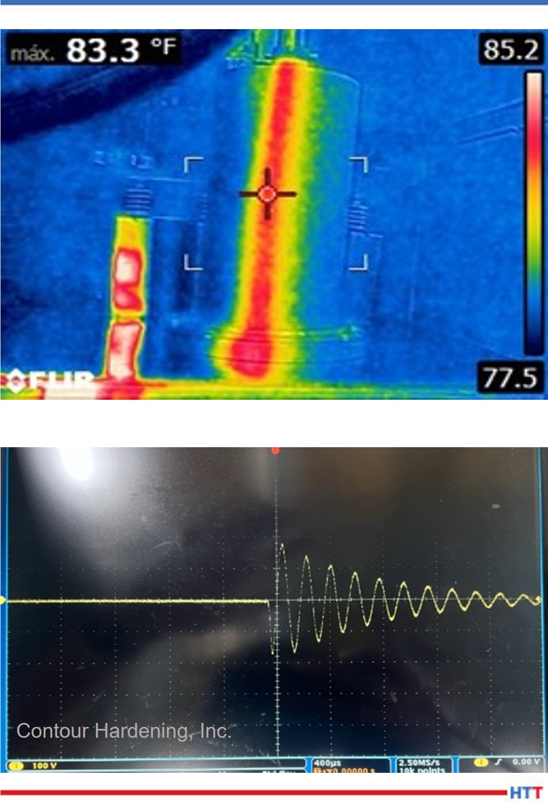
Contour Hardening, Inc.
Cuando el sistema se encuentre trabajando en óptimas condiciones, genera un plan de medición el cual te permita recopilar información de puntos específi cos dentro del sistema. Una vez que se vuelva a presentar una nueva falla puedes comparar las mediciones de falla contra las del buen funcionamiento. Algunos ejemplos de mediciones pueden ser:
- Temperatura
- Voltaje
- Corriente eléctrica
- Resistencia y capacitancia
- Formas de onda
En resumen
Una metodología de trabajo ordenada y documentada, un buen catálogo de piezas de recambio, junto con las herramientas de trabajo necesarias, pueden ser elementos clave para entender un problema y, lo que es más importante, resolverlo de forma eficaz.
Es vital que los profesionales se capaciten de manera constante para mejorar los tiempos de paro debido a fallas en los sistemas de inducción. La capacitación relacionada con procesos metalúrgicos sería una buena forma de complementar tus habilidades de resolución de problemas permitiéndote interpretar las características de los sistemas de inducción, al igual que de los elementos que los componen.
Bibliografía
Valery Rudnev and George Totten, ed., ASM Handbook Volume 4C: Induction Heating and Heat Treatment, (Materials Park, OH: ASM International Heat Treating Society, 2014), 581- 583
Sobre el autor: Alberto C. Ramirez es ingeniero en Mecatrónica egresado del Instituto Tecnológico Nacional de México Campus León con una maestría en Administración de Tecnologías de la Información por el Instituto Tecnológico de Monterrey. Cuenta con más de 8 años de experiencia en fuentes de alimentación, gestión de proyectos, mantenimiento y automatización. Actualmente se desempeña como ingeniero de fuentes de alimentación y automatización en Contour Indianapolis. Alberto inició su carrera en la fi lial de Contour en México y debido a su dedicación forma parte del staff en los Estados Unidos.
He is also an honoree from Heat Treat Today's 40 Under 40 Class of 2021.
Para más información:
Contacta a Alberto escribiendo a: aramirez@contourhardening.com.
 Find heat treating products and services when you search on Heat Treat Buyers Guide.com

10 pasos para solucionar las fallas en un equipo de inducción Read More »


 Rapid Air Tempering


 Heat Treat