We all know that cooling off the right way matters. Your friend may be hot, but dumping a bucket of ice on them just might cause your friendship to crack. The same applies to heat treating. The methods and modes of cooling operations can make or break our bank and equipment.
Heat TreatToday has coalesced technical information across articles and podcast episodes from key experts, including a case study comparing the efficiency of different cooling technologies, a Heat Treat Radioepisode full of purchasing guidance and the updates on the latest technologies, and finally a helpful comparative of cooling systems for the automotive industry.
Discover more about these three topics in today’s Technical Tuesday original content feature.
Intelligent Cooling System Improves Operations for Alloy Manufacturer: A Case Study
There’s only one constant about technology: It’s always evolving — revealing new innovations and opportunities. And as these new technologies come to light, heat treating operations have new opportunities to reduce cost, increase efficiency, and ensure consistent, optimized part quality, regardless of the job parameters. With the introduction of new process cooling technologies to the heat treating market, previously unexplored systems become viable solutions for unanswered operating challenges. Gary Burdardt, market development manager with Frigel North America, authored a case study to explore new technologies in cooling operations.
“Located on the East Coast, the manufacturer needed to find an alternative process cooling solution for its vacuum furnace cooling operation. It had been using air-cooled chillers, but the costs of continuous operation were too high. Operating as a batch furnace, the heat load of this particular application was specified to be approximately 200 tons, and process cooling water temperature, which was specified at 70°F, presented a significant challenge.”
Heat Treat Radio #100: Cooling Off the Heat (Treat)!
Keeping your heat treat equipment cool is as critical as it is an oxymoron. If you have old cooling systems or are looking to purchase new ones, hear from Matt Reed, director of Sales and Technologies at Dry Coolers, as he shares purchasing considerations, maintenance, and latest technologies with Heat TreatRadio host, Doug Glenn. Learn about the importance of flow, sediment build up, hot spots, and more!
“Vacuum furnaces, around the 1960s and 1970s, when they were being developed, focused on heat treating materials. Cooling is required because you’ve got these inner walled jackets in the furnace, jackets in the heads, you’ve got diffusion pumps, mechanical pumps — all these ancillary pieces of equipment that require cooling. Originally, you could use city water and flow city water right through the furnace. Customers soon find out that that’s a lot of water consumption, so the next step was to look at an evaporative cooling tower. You start recirculating evaporative cooling tower water directly through the furnaces.”
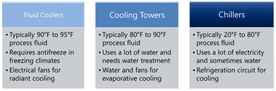
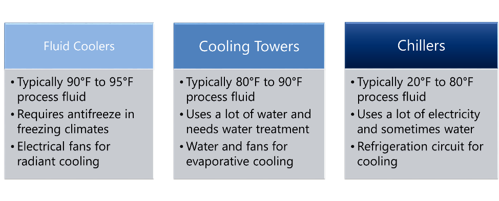
Deciding on a process cooling system for your automotive heat treat requires intentional consideration. In this article Bob Smith, director of product management at Thermal Care, offers practical and valuable guidance on three options: fluid coolers, cooling towers, and chillers.
“When considering which type of process fluid cooling system is best for your automotive heat treat application, it is important to determine the process fluid medium, desired temperature, and the significance of operating cost versus initial investment. There are often multiple solutions to a process cooling application, and the following is intended to provide a basic outline of the types of systems available and where they are best used.”
One of the great benefits of a community of heat treaters is the opportunity to challenge old habits and look at new ways of doing things. Heat TreatToday’s101 Heat TreatTipsis another opportunity to learn the tips, tricks, and hacks shared by some of the industry’s foremost experts.
Today’s tips are the 1 – 2 – 3! They come to us from Dry Coolers with a word on cooling system growth capability; Bloom Engineering Company Inc. on the importance of careful spending; and Rick Kaletsky, Safety Consultant about clear content labeling.
Heat TreatTip #1
Buy a Cooling System Capable of Growth
Plan for future growth. It is more cost effective to provide additional capacity while equipment is being installed. Simple planning for the addition of future pumps (e.g. providing extra valved ports on tanks) and space for heat transfer equipment (e.g. pouring a larger pad or adding extra piers) can save considerable money down the road with little upfront expenditure. Consider installing one size larger piping for the main distribution supply and return; if this is not possible, make sure you can add an additional piping run on the hangers you will install now. Above all, be sure to include all necessary drains, vents, isolation valves, and plenty of instrumentation. These items are critical aids in maintenance, troubleshooting, and future system expansion. (Dry Coolers)
Thinking about future growth will help you choose the right cooling system.
Heat TreatTip #2
Never Go Cheap on These Two Things
There are 2 things in life you should never go cheap on: Toilet paper and combustion equipment! When upgrading or looking at new systems, spend the money to do it right. Designing on the cheap will only lead to operational and maintenance headaches. And trying to reuse the ancient artifacts when upgrading just to save a buck will cost you 10x that down the road. You don’t have to break your budget to do a quality job! (Bloom Engineering Co. Inc.)
Heat TreatTip #3
Container Clarity Counts!
Assure that container label wording (specifically for identifying chemical contents) matches the corresponding safety data sheets (SDS). Obvious? I have seen situations where the label wording was legible and accurate and there was a matching safety data sheet for the contents, but there was still a problem. The SDS could not be readily located, as it was filed under a chemical synonym, or it was filed under a chemical name, whereas the container displayed a brand name. A few companies label each container with (for instance) a bold number that is set within a large, colored dot. The number refers to the exact corresponding SDS. (Rick Kaletsky, Safety Consultant)
Unclear labeling of chemical materials creates a hazardous situation.
This week’s Technical Tuesday installment is a Heat Treat Today original from our upcoming Automotive magazine, which is scheduled to be released in June.
Deciding on a process cooling system for your automotive heat treat needs is an important process that needs intentional consideration. Check out this practical and valuable guidance from Bob Smith, director of product management at Thermal Care to help you make an informed decision.
When considering which type of process fluid cooling system is best for your automotive heat treat application, it is important to determine the process fluid medium, desired temperature, and the significance of operating cost versus initial investment. There are often multiple solutions to a process cooling application, and the following is intended to provide a basic outline of the types of systems available and where they are best used.
Process cooling is moving heat from where it is not wanted (the process), and putting it into the air outside the manufacturing facility. Heat transfer usually involves the use of some sort of heat transfer media, usually a fluid like water or a glycol solution, to transport the heat from the process equipment to the cooling system.
The first step is to understand the required temperature for the process cooling fluid in order to properly remove heat from the process. This is typically specified by the process machine manufacturer and is based on the flow of fluid and the required temperatures of their heat exchangers. There are three basic types of process cooling systems to consider.
Fluid Coolers
Fluid cooler systems are commonly used for applications with warmer temperatures. They consist of copper tubes with aluminum fins and fans that act like a radiator to cool the process fluid using ambient air. The coolest practical leaving fluid temperature is about 10°F warmer than the air entering the fluid cooler. Compared to cooling towers, fluid coolers are not as energy efficient, have a higher initial cost, and have a larger footprint; however, they have much lower maintenance requirements and use less water than cooling towers. Of the three types of process cooling systems, the operating cost and capital investment of fluid cooler systems typically fall somewhere between that of a cooling tower and chiller system.
Fluid coolers use less water but are limited by the temperature of ambient air
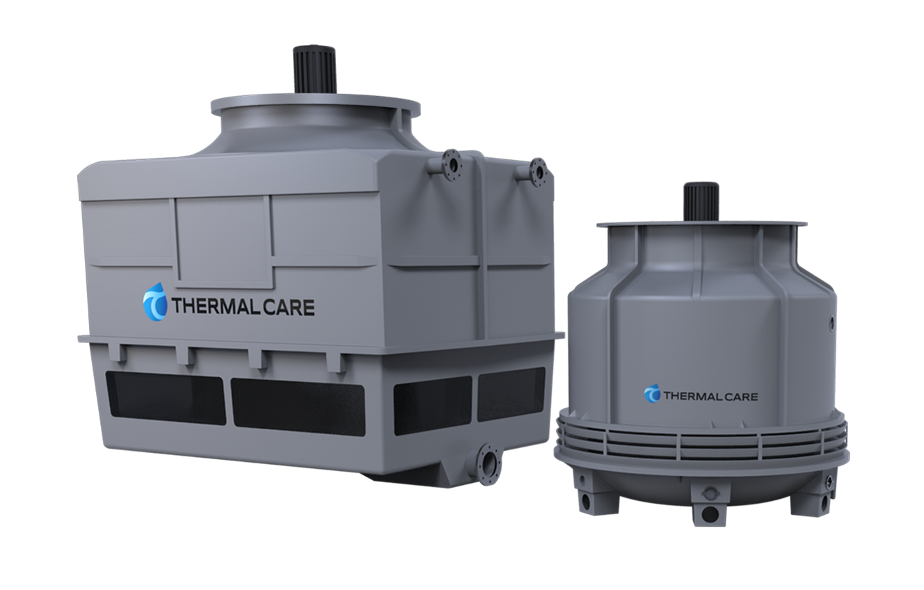
Cooling Towers
Cooling tower systems are used for applications where a fluid cooler is not able to get cold enough. A cooling tower system can provide a reliable source of cool water year-round in the 70°F to 100°F temperature range. Cooling towers work through the process of evaporation. Water is sprayed over plastic cooling tower fill, which creates a large surface for water to evaporate from. A fan moves air through the tower to induce evaporation, which in turn cools the water. The coolest practical leaving water temperature in summer is about 80°F due to air temperature and humidity. Cooling tower systems are typically the least expensive of the three types of systems to operate; however, the maintenance requirements for filtration and water treatment are the highest of the three.
Cooling towers use water to maximize evaporation for cooling
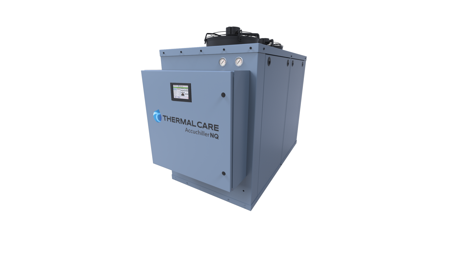
Chillers
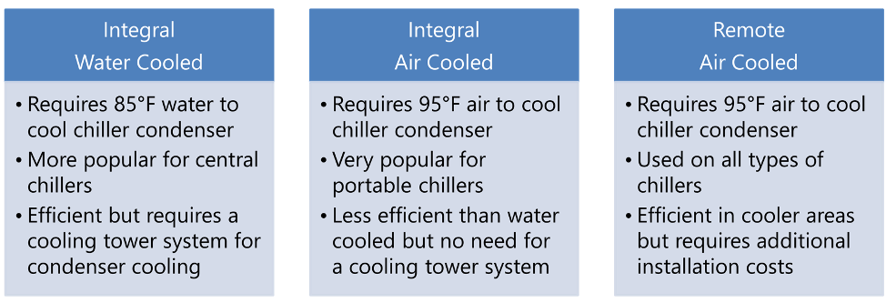
Chiller systems are used in applications where neither a fluid cooler, nor cooling tower system, can get cool enough to meet the requirements for the process. In a chiller, refrigerant is used to pull heat from the process fluid and transfer it to ambient air or cooling tower water. Most applications are for 50°F water, but most chillers have a practical process fluid set point range of 20°F to 80°F. Of the three types of cooling systems, chiller systems are the most expensive to purchase and operate. Chillers require some form of cooling to their condensers, which is where the refrigerant gas that was boiled using the process heat is condensed back to a liquid. The three types of chiller condensers are shown below.
Chillers that use air-cooled condensers have less maintenance and less installation costs than water-cooled condensers, because water-cooled condenser chillers require a fluid cooler or cooling tower system to generate 85°F to 90°F fluid to cool the condenser of the chiller.
Chillers use refrigerant to pull heat from the process fluid
With the above basics you will be able to choose which type of cooling system you should consider to cool your process. Once that is known it is best to work with a manufacturer who specializes in that type of process cooling equipment. They will have the expertise and knowledge to help you configure the best system solution and ensure you are able to meet your purchase and operating cost objectives.
Bob Smith, director of product management, Thermal Care
Bob Smith, director of Product Management, has over 30 years of experience at Thermal Care having begun as a sales engineer. He has grown with the company over the years serving in a number of different roles such as project manager, inside sales manager, OEM market manager, and director of Plastics Markets.
For more information, contact: www.thermalcare.com or (888)-828-7387
Scientists from the Alliance for the Development of Additive Processing Technologies (ADAPT) at Colorado School of Mines who took part in an international research team have helped develop a nickel-titanium elastocaloric cooling shape memory alloy (SMA) that is highly efficient, eco-friendly, and easily scaled up. The alloys, in which hafnium acts as a strengthening precipitate, hold the promise of requiring only heat treatment to attain functional shape memory performance.
The international team, led by University of Maryland Professor Ichiro Takeuchi, developed the improved elastocaloric cooling material using a blend of nickel and titanium metals, fabricated by a 3D printer, that is not only potentially more efficient than current technology, but is completely “green.” Moreover, it can be quickly scaled for use in larger devices.
Dr. Aaron Stebner, Rowlinson Associate Professor of Mechanical Engineering
“The key finding of the research is that while elastocaloric materials typically used for solid-state cooling show a degradation in cooling behavior after hundreds of cycles, laser melting these metals creates fatigue-resistant nanocomposite microstructures that can cycle, with consistent cooling capacity, a million times,” said Aaron Stebner, Rowlinson Associate Professor of Mechanical Engineering and a co-author of the paper.
Professor Ichiro Takeuchi, Graduate Program Director in Materials Science and Engineering, University of Maryland
“Dr. Stebner’s expertise played a crucial role in developing understanding of the fundamental mechanism behind fatigue-resistant behavior of additively manufactured shape memory alloys. His group’s in situ synchrotron diffraction and finite element modeling capabilities gave us unique insight into the inner workings of the material,” Prof. Takeuchi said.
The work, which was published in the Nov. 29 issue of Science, is the result of a collaboration led by researchers from the University of Maryland, together with Ames Laboratory, Mines, Iowa State University, and China’s Xi’an Jiaotong University.
Heat Treat 2019 was just a month ago, and one of the great benefits of gathering with a community of heat treaters is the opportunity to challenge old habits and look at new ways of doing things. Heat TreatToday’s101 Heat TreatTips is another opportunity to learn the tips, tricks, and hacks shared by some of the industry’s foremost experts.
Today’s Technical Tuesday features tips from Grammer Vacuum Technologies covering Vacuum Furnace and Cooilng.
If you have a heat treat-related tip that would benefit your industry colleagues, you can submit your tip(s) to doug@heattreattoday.com or editor@heattreattoday.com.
Heat TreatTip #59
Oxygen Contamination Sources
A common source of oxygen contamination to vacuum furnace systems is in the inert gas delivery system. After installation of the delivery lines, as a minimum, the lines should be pressurized and then soap-bubble tested for leaks. But even better for critical applications is to attach a vacuum pump and helium leak detector to these lines with all valves securely closed, pull a good vacuum, and helium leak check the delivery line system. Helium is a much smaller molecule than oxygen and a helium-tight line is an air-tight line. Also, NEVER use quick disconnect fittings on your inert gas delivery system to pull off inert gas for other applications unless you first install tight shut-off valves before the quick disconnect. When the quick disconnect is not in use, these valves should be kept closed at all times. (Though the line is under pressure, when you open a back-fill valve to a large chamber, the line can briefly go negative pressure and pull in air through a one-way sealing quick disconnect valve.)
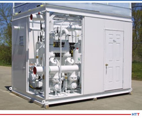
Air-cooled vacuum furnace cooling system (from Dry Coolers)
Heat TreatTip #80
Closed-Loop Water Cooling Systems
Modern water cooling systems for vacuum furnaces are typically closed-loop. (By this we mean that air never comes in contact with the water that goes through your vacuum furnace. The expansion tank would be pressurized with dry nitrogen, in this case, to prevent oxygen pick-up by the water.) Sometimes after maintenance work, the expansion tank or sump is left open to air. As a result, air/oxygen, dirt, and organic materials can get into the water system and eventually cause both corrosion and plugging of your chamber. A plugged chamber can overheat and explode or implode causing serious injury or death. Replacement chambers are very expensive. A recirculating water system that allows air to contact the water entering your furnace can dramatically decrease the life of your vacuum chamber.
Heat TreatTip #89
Lanthanated Moly Alloy Strip Increases Element Longevity
Moly and TZM moly grids can double or triple vacuum furnace throughput by using a two-tier or three-tier fixture to utilize unused work zone space.
Pure molybdenum vacuum furnace heating elements distort with time in service due to growth and contraction during thermal cycling. You can often see this distortion beginning just a month or two into service of new elements. Eventually, these will contact either the insulation/shield wall— or worse yet, your parts—and cause electrical arcing. So they need to be replaced before this happens. By making a direct replacement of these pure moly strips with a lanthanated moly alloy strip, the life of the elements can be significantly increased. We have seen a rough doubling of the element life by making this change. Many new OEM vacuum furnaces are now supplied with lanthanated elements at the start. OEM and aftermarket hot zone re-builders are frequently making this change as well to get longer life out of their hot zone elements.
Heat TreatTip #101
TZM Moly Alloy for Structural Vacuum Furnace Components
For over 30 years, there has been a molybdenum alloy called TZM (Moly-0.5%Ti-0.1%Zr) which is far superior to pure molybdenum in vacuum furnace structural applications. TZM is slightly more expensive than pure moly, so OEM furnace companies use pure moly to keep their costs down for competitive reasons. But they could be offering it as an option for their buyers. Pure molybdenum metal undergoes recrystallization at temperatures as low as 2000°F. The recrystallized structure is very brittle at the grain boundaries, resulting in a structural component that also is very brittle. If you have a vacuum furnace with moly components, you have undoubtedly seen this with older parts. TZM alloy, however, does not recrystallize until around 2500°F, and even then it does not exhibit the brittle behavior of pure moly, because the recrystallized grain size is still very fine. TZM is also stronger than pure moly, as much as 3 to 4 times the strength at temperatures above 2000°F. For a 10-15% premium in cost, you can dramatically extend the life of your moly structural components in your furnaces.
Heat TreatToday recently released the latest round of 101 Heat TreatTips in the fall 2019 issue of Heat TreatToday (click here for the digital edition). One of the great benefits of gathering with a community of heat treaters is the opportunity to challenge old habits and look at new ways of doing things. The Heat TreatTips is another opportunity to learn the tips, tricks, and hacks shared by some of the industry’s foremost experts.
Ryan Neiss of Taylor Winfield Technologies
Today’s Technical Tuesday features a tip on Induction Heating that missed inclusion in the magazine, but it’s significant enough to get its own headline. From Ryan Neiss of Taylor Winfield Technologies, we bring you “Seasonal Cooling Water Adjustments for Induction Power Supplies”.
If you have a heat treat-related tip that would benefit your industry colleagues, you can submit your tip(s) to doug@heattreattoday.com or editor@heattreattoday.com.
Heat TreatTip: Induction Heat Treating
Seasonal Cooling Water Adjustments for Induction Power Supplies
A proper preventative maintenance plan is critical to the performance of induction heating power supplies. One of the main culprits of downtime is reduced water flow and water quality. While water quality is a very important topic that must be maintained within the OEM specifications, this tip is going to address the importance of seasonal water adjustments.
Water flows through the inside of the power supply cooling critical devices, like power semiconductors, capacitors, transformers, buss, etc. If the temperature is not adjusted for seasonal climate changes, many users may experience water condensation inside the power supply cabinet. This is not a good situation, because the uncontained water can drip into places where water should not be and potentially cause severe damage to the power supply. Depending on how much water damage there is will determine the amount of production loss and costs of this easily preventable mistake.
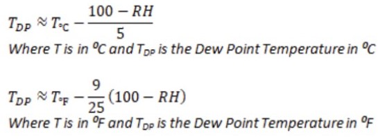
The temperature setpoints for your cooled water source must always be above the temperature dew point in order to prevent condensation. Most weather apps have current dew points, relative humidity, and temperature. Additional climatic resources for predictive planning include noaa.gov and ashrae.org.
Here’s a simple approximation of the dew point temperature from temperature and relative humidity (only apply if relative humidity is above 50%).
Gary Burdardt, market development manager with Frigel North America
There’s only one constant about technology. It’s always evolving—revealing new innovations and opportunities. And as these new technologies come to light, heat treating operations have new opportunities to reduce cost, increase efficiency, and ensure consistent, optimized part quality, regardless of the job parameters. With the introduction of new process cooling technologies to the heat-treating market, previously unexplored systems become viable solutions for unanswered operating challenges.
When a tempered alloy manufacturer faced strict job requirements that demanded capabilities outside the competences of traditional technologies, a modular process cooling systems designer and manufacturer based in Italy with a North American operation located in East Dundee, Illinois, proposed a process cooling system that addressed key problem areas, while ensuring top system performance. As a result, the company was able to document operational cost savings of over $80,000 per year.
Gary Burdardt, market development manager with Frigel North America, is the author of this case study.
The Need for a Better Cooling Solution
Located on the East Coast, the manufacturer needed to find an alternative process cooling solution for its vacuum furnace cooling operation. It had been using air-cooled chillers, but the costs of continuous operation were too high. Operating as a batch furnace, the heat load of this particular application was specified to be approximately 200 tons, and process cooling water temperature, which was specified at 70°F, presented a significant challenge.
At 70°F, the required temperature was much lower than typical process cooling temperatures. For many vacuum furnace cooling processes, water temperatures can be specified as warm as 100°F for successful heat extraction. Because furnace vessels and resulting materials can reach temperatures as high as 1,300 to 1,700°F, water temperatures of at or near 100°F are able to maintain furnace vessel inner wall temperatures below a maximum (safe) temperature of 300°F. Though the final part temperature can be inconsequential, the batch of product needs to be cooled enough for comfortable handling in downstream operations.
Traditional technologies are capable of maintaining 100°F cooling water year-round. Maintaining temperatures consistently at 70°F is much more difficult. Facing high costs and strict temperature requirements, the manufacturer needed a new process cooling approach.
In this application, the manufacturer identified several process cooling areas of concern that, left unsolved, could jeopardize operations.
First and foremost, process cooling systems needed to adequately reduce heat transmission from the furnace vessel to the ambient environment. In addition, the air-to-water heat exchanger, used for batch cooling inside the chamber, needed to be cooled after the tempering process was complete. Likewise, the diffusion pump, used to evacuate air from the vacuum chamber, as well as the electrical cabinet relied on process cooling for optimized function. If the diffusion pump failed to perform as expected, part quality would be jeopardized, leading to potential contamination and material inconsistencies, and reducing the value of the final product.
Traditional Technology Limitations Explored
Initial investigations into solutions revealed apparent limitations. Traditional process cooling methods were unable to cost-effectively maintain water-cooling temperatures of 70°F. This made finding an alternative solution critical. Three traditional methods were explored:
Evaporative cooling towers
This technology is incapable of achieving consistent temperatures in the 70°F range. Cooling water temperatures are controlled by the wet-bulb temperature, relying on evaporation in ambient air conditions. As a result, they can often only provide 85°F or higher water temperatures to processes year-round. This cooling technology tends to be maintenance-intensive given the reliance on chemical treatment and filtration to maintain water quality. Additionally, evaporative towers consume excessive amounts of water.
Dry fluid coolers
This technology would only be effective in this application when air temperatures were at 55°F or below. Though reducing the need for chemical treatments and eliminating excessive water consumption, this system can only produce water that is typically 10-15 degrees warmer than the dry-bulb temperature, or the ambient air temperature without moisture. As a result, temperature tolerance would be lost during the warmer months. During the colder months, the use of glycol antifreeze solutions is necessary to maintain system functionality, which in many cases requires the use of additional pumping systems and water-to-glycol heat exchangers.
Central chillers
The conventional approach relies on a chilled water system that incorporates chillers to generate 70°F temperatures. This system can be supplemented with a dry fluid cooler if conditions for free cooling were significant enough for payback in three years or less. In many cases, the cold, consistent temperature of the water produced by the chillers is cooler than is necessary for most heat-treating components, leading to increased energy inefficiencies and accrued higher costs.
Faced with the limitations of traditional technologies, the manufacturer turned to an alternative process cooling system for the answer.
Considering an Alternative System
Once traditional methods were thoroughly analyzed, the choice was easy. Providing an alternative solution, the Frigel system design was selected and implemented into the vacuum furnace cooling application.
Frigel’s Intelligent Process Cooling systems are designed to create better processes for heat treating operations and provide a unique, flexible solution. The solution combines the use of its internationally patented closed-loop adiabatic fluid cooler with small, dedicated chillers to maximize opportunities for free cooling while ensuring consistent and reliable process cooling temperatures. The closed-loop adiabatic fluid cooler operates outside of the facility, with chillers located near each work cell or process. This approach allows for greater flexibility as individual process cooling needs change.
As a closed-loop system, it requires fewer resources and creates additional opportunities for free cooling capabilities. Water consumption is greatly reduced as opportunities for evaporation are removed. Water consumption is lowered by as much as 95% when compared to an evaporative cooling tower. The closed-loop system also prevents process cooling water from being exposed to the outside air, reducing the need for chemical treatments and additional filtration efforts.
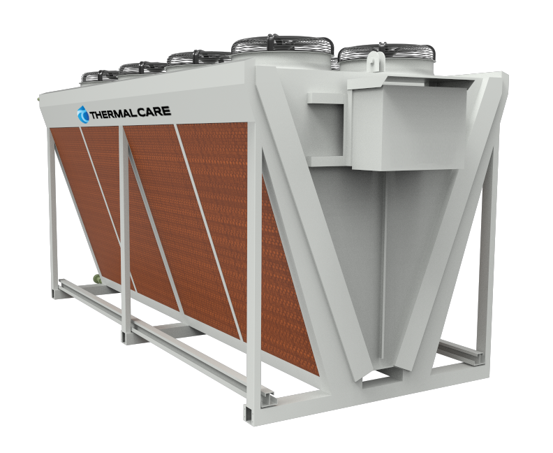
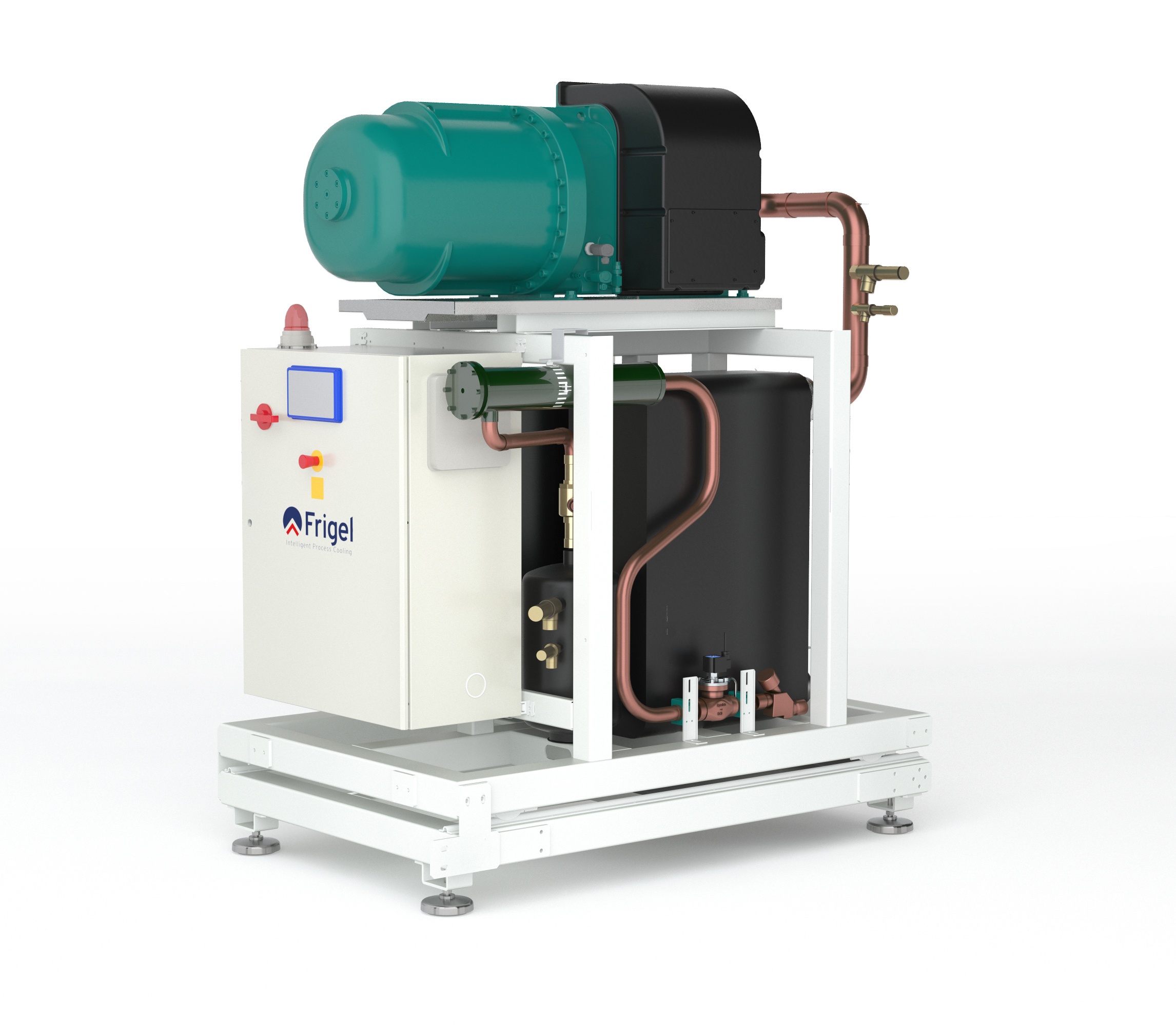
Frigel 3FX chiller
When compared to an evaporative cooling tower, chemical use can be reduced by as much as 40%, appealing to strict municipal water quality regulations while improving system reliability and uptime. Maintenance issues are also drastically reduced in comparison to open-loop systems. Contamination, corrosion, and deposits are all threats to machine performance. By reducing opportunities for cooling coils to interact with moisture, and cooling water exposure to the open air, maintenance-intensive issues are lessened. As a result, production uptime is optimized.
The closed loop-adiabatic cooler system also allows for greater free-cooling opportunities. When ambient conditions are appropriate, localized chillers are bypassed. Instead, heat is transferred to the air via copper tubes in the adiabatic chamber of the fluid cooler, and the cooled water is returned to the furnace vessel. Meanwhile, localized chiller compressors are automatically shut down, saving energy and reducing costs. Working together, the closed-loop adiabatic cooler system and localized chillers are able to provide cooling water temperatures at a wider range of ambient conditions, allowing greater flexibility throughout the heat-treating process.
Additionally, an Intelligent Process Cooling system provides a modular solution. With the fluctuation of job demands and shifting job requirements, the system can expand to fit each unique process cooling need. The use of dedicated chillers allows work cells to be self-contained, reducing disruption and downtime as new process cooling requirements adapt and develop with business growth.
Applying the Intelligent Process Cooling System
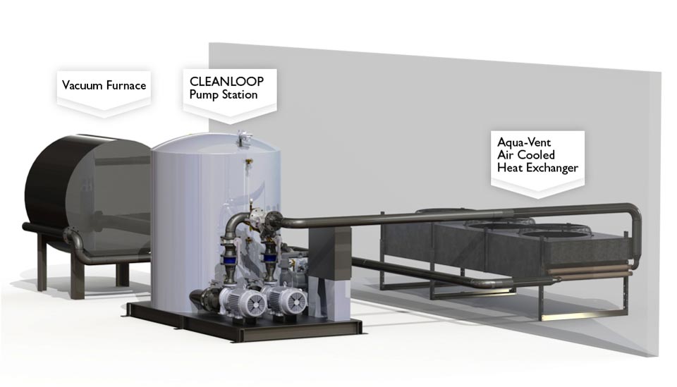
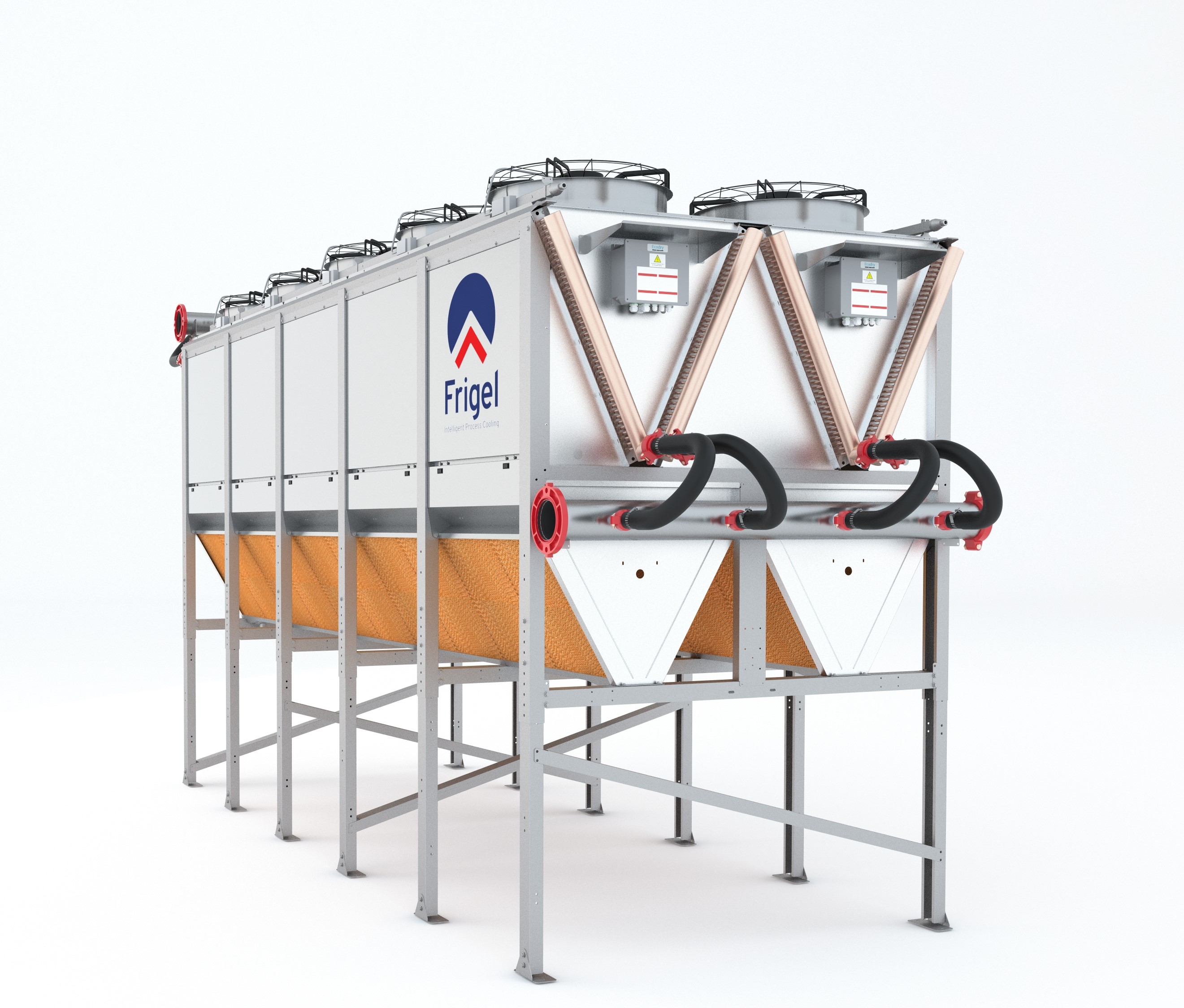
At the East Coast manufacturer’s operation, a Frigel Ecodry internationally patented closed-loop adiabatic fluid cooler operates outside the facility. The Ecodry unit is used in combination with dedicated Frigel 3FX water-cooled chillers inside the facility to maximize opportunities for free cooling while ensuring consistent and reliable process cooling temperatures.
At the alloy manufacturer, the Intelligent Process Cooling system installed includes an Ecodry fluid cooler with a patented adiabatic chamber and several water-cooled chillers.
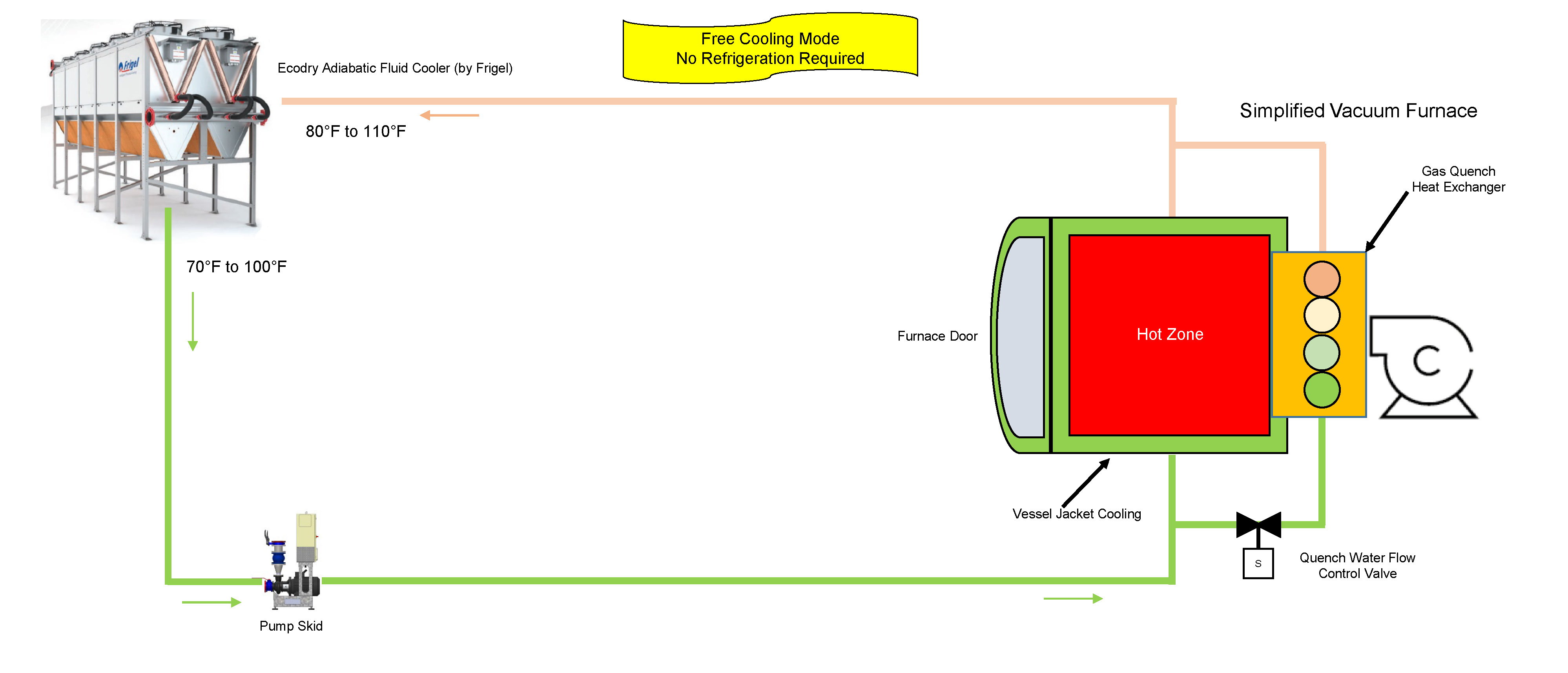
Throughout the year, this system leverages free cooling when ambient conditions permit (see Figure 1). For this manufacturer, the installation location provides ambient temperatures that are quite mild, reducing the necessity for localized chillers from approximately the beginning of October to the end of April. Instead, process cooling water transfers heat to the ambient air via the copper tube and aluminum coils in the adiabatic fluid cooler. Once cooled, water travels to the pump skid, then returns to the furnace vessel where it cools the furnace jacket, furnace door, diffusion pump, and heat exchanger.
Figure 1. The Frigel Intelligent Process Cooling system leveraging free-cooling opportunities.
While the furnace is in processing mode, process cooling water runs between the shells of the vacuum, cooling the inner walls, furnace jacket, furnace door, and diffusion pump. This ensures the furnace exterior maintains a safe temperature and the diffusion pump is able to sustain necessary atmospheric pressure within the furnace vessel. Following the completion of the processing cycle, the quench water flow control valve sends process cooling water to the heat exchanger, decreasing furnace vessel temperatures to the desired temperature for part handling and extraction.
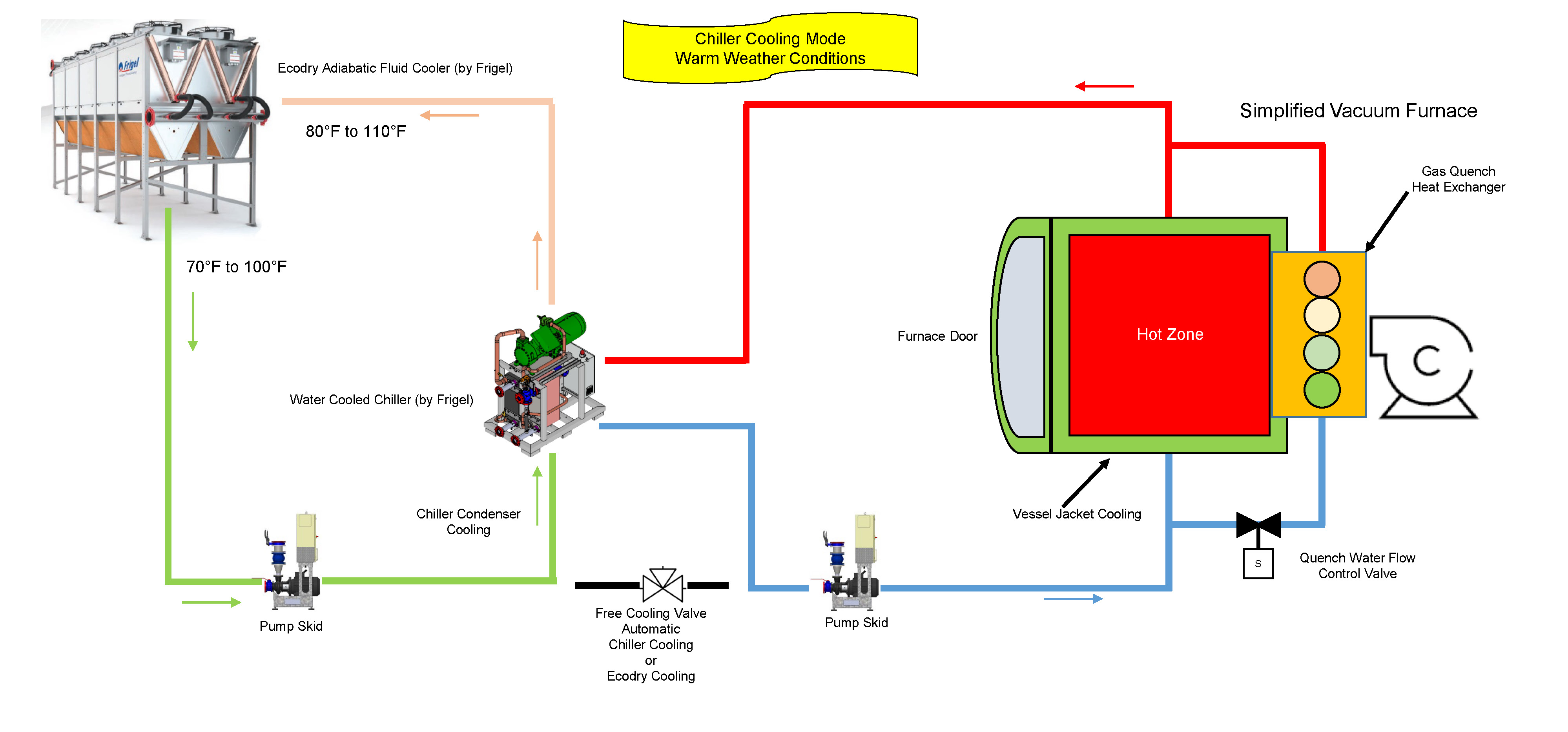
Existing water-cooled chillers supplement the cooling process during the rest of the year when set temperatures can no longer be maintained with the use of free cooling (see Figure 2). When temperatures are at their highest, the water-cooled chillers generate the 70°F coolant and the heat is transferred to the Ecodry loop via the chiller condensers. From there, the chilled water travels to the furnace vessel, cooling the furnace components. Once the water has passed through the process, it returns to the adiabatic fluid cooler, and the water-cooling process begins once again.
Figure 2. The Frigel system leverages chiller cooling mode in warm weather conditions.
If and when ambient temperatures exceed 85°F, the adiabatic chamber of the fluid cooler initiates the spray system to lower incoming air temperatures closer to the wet-bulb temperature. By doing so, the coolant is lowered to a temperature that maintains reliable, efficient operations.
Operational Savings of $80,000 Per Year and More
By leveraging a closed-loop system with an adiabatic chamber, the alloy manufacturer achieved benefits that weren’t possible with traditional technologies. Chiller run time is in the 1,500 hour-per-year range and adiabatic cooling is required less than 400 hours per year. Compared to an evaporative cooling tower and water-cooled chiller system, water use has been reduced by 95% and electrical energy costs have been reduced by 60%. Increased efficiencies and reduced water consumption have resulted in operating costs that are dramatically less than any other system. In total, the plant saves over $80,000 per year with the Frigel system.
For this manufacturer, an alternative solution to traditional process cooling technologies was the only viable option. High costs drove innovation and a need for a better approach. Frigel’s Intelligent Process Cooling system, leveraging the capabilities of a closed-loop adiabatic system and localized water-cooled chillers, allowed for greater operational flexibility while reducing costs and maximizing efficiency—providing the manufacturer with a better process cooling solution.
About the Author
Gary Burgardt, Frigel North America’s market development manager, works closely with prospects and customers to ensure every Frigel process cooling solution delivers measurable results based on each company’s unique processes and business goals. In addition to expertise in Intelligent Process Cooling, Burgardt leverages 30 years of experience in process cooling across a wide range of industries to assist customers at every stage of the planning and buying process.
It’s frustrating enough for furnace operators to encounter downtime due to failure or faulty equipment, but more so when it can be avoided adhering to basic maintenance procedures and adopting habits of diligence and quick thinking.
Andrew Alborghetti of TAV Vacuum Furnaces offers “5 tips for preventing faults caused by the process water in the cooling system [of a vacuum furnace or by] the use of unsuitable equipment.” In addition, he suggests steps to take when an emergency develops.
In a nutshell,
Maintain specific purity standards of the process water.
Prevent dangerous enrichment by maintaining valves.
Keep an eye on your process water temperature.
Avoid damage from external cold temperatures.
Consider investing in a closed circuit adiabaticwater cooling system.
An excerpt:
“For the vacuum furnace to meet the considerable need for water it must have sufficient capacity (tub or tank) to quickly transfer heat from the furnace and from the load. The capacity of the tank determines the size of the system for cooling the water contained in it. Of course, the bigger the tank, the smaller the water cooling system it contains. When there are numerous furnaces, the size of the tank is calculated based on averaged values for behavior in the respective heat cycles.” ~ TAV Vacuum Furnaces
Click below for more on the 5 tips as well as steps you can take should your shop face an emergency such as a power outage that affects the water cooling system
“Just like your plant electrical system, telecommunications equipment, or data network infrastructure, a process cooling water failure can shut down a facility and may even involve safety issues. Let’s outline some of the steps you can take to minimize downtime.”