Piotr Zawistowski Managing Director SECO/VACUUM TECHNOLOGIES, USA
Source: secowarwick.com
A new vacuum furnace for a division of the US Department of Defense will bolster its capability to ensure supply chain reliability. The furnace is equipped to handle steel hardening, surface engineering, vacuum annealing, nickel alloy processing, and titanium heat treatment.
As a critical supplier of aerospace components to the US Department of Defense, this division will use the new vacuum oil quenching furnace, provided by SECO/WARWICK, Group, to handle functions of the department’s existing heat treatment furnaces and expand their capabilities. The addition of low pressure carburizing (LPC) and high pressure gas quenching (HPGQ) is new to this location.
“Assuring redundancy in heating needs of this location was critical,” said Piotr Zawistowski, Managing Director of SECO/VACUUM.
In this episode, Heat TreatRadio host Doug Glenn talks with Joe Powell of Integrated Heat Treating Solutions in this fourth and final episode about bringing heat treating into the 21st century. This episode covers Direct from Forge Intensive Quenching – forge shops, listen up!
You are about to listen to the 4th and final episode in a series on rethinking heat treatment, with Joe Powell, of Integrated Heat Treating Solutions. You can find the previous episodes at www.heattreattoday.com/radio.
Below, you can either listen to the podcast by clicking on the audio play button, or you can read an edited version of the transcript.
The following transcript has been edited for your reading enjoyment.
DG: Joe, if you don't mind, take us on a 30,000 foot overview of what you've been doing at Integrated Heat Treating Solutions.
JP: What we've been doing for the past 23 years at Integrated Heat Treating Solutions and the last 75 years at Akron Steel Treating is applying heat treatments to parts made by others. We had over 1200 customers on our customer list at Akron Steel Treating and they use various materials. We kind of grew up in the shadow of the Cleveland market, which is the largest market for heat treaters, and there is the largest number of commercial heat treaters in the Cleveland market. This was possibly outnumbered by Detroit at one time, but I still think that we're probably the number one market for heat treating in this part of the country.
What has happened over the last century, in the 20th century, is that heat treating has become very, very good. New equipment has been developed like controls, thermocouples, oxygen probes, vacuum furnaces, vacuum quenching, high pressure vacuum quenching, oil skimmers, new quenchants made with reverse solubility polymers - all of these things have come together and made heat treating very, very good. However, as part of that, there has been a commoditization of heat treatment. That means that heat treating became so good that parts rarely crack or distort unacceptably, and companies have devised methods for correcting the distortion through hard turning, grinding, straightening, flattening, you name it. And the part makers and the heat treaters got along, in a kind of peaceful coalition, to get the parts out the door to the end user.
However, in the 21st century, that is just not good enough. In lean manufacturing, you have to offer an integrated solution for what you're doing. The entire value chain for making a product has to be on the same page; they have to be in alignment. The processes have to be in the proper order. What we're trying to do with Integrated Heat Treating Solutions is bring the last dimension of part design, what we call the Z dimension, to the part makers, their designers, and their material suppliers, so that we present a solution that delivers the optimal amount of value and eliminates the waste from heat treatment, or forging, as we'll talk about today.
[1] Defense Logistics Agency, "About," https://www.dla.mil/AboutDLA/ [2] DFIQ FIA Technical Committee Presentation, "Evaluation of Intensive Quenching Hardening Process Immediately After Completion of Hot Forging Operations," 2018. [3] Forging Process Improvement Using Intensive Quench, 2019.DG: Right. In these four episodes we've been talking to people about bringing heat treating into the 21st century. On your website, integratedheattreatingsolutions.com, there is a good illustration table that shows what heat treating was like in the 20th century and what it is like in the 21st century. That's basically what we're talking about. Just a quick recap of the previous three podcasts we've done: It all revolves around a customized heating, but more importantly, a customized quenching of materials so that the distortion of those parts is predictable, and that the part design can be altered so that there is essentially no post heat treatment processing. In other words, you can pretty much eliminate grinding or any type of machining, straightening, and that type of thing. Once heat treated and quenched with the technologies that you're talking about, the part is essentially pack and go.
We've talked about several examples, but the two we talked about in the recent podcasts were an 18” bevel gear, which was quite interesting. Then we talked about a fracking pump valve seat, which was also quenched in this way. So today, you and I want to talk about, as you alluded to, the forging industry. We're going to talk about something called (direct from the) forge intensive quenching (DFIQ). If you don't mind, tell us what that is. For those people in the forging industry, what is direct from forge intensive quenching?
JP: It's the principle that the forging processes use a lot of BTUs of heat to heat up a billet, and then bang it into a shape and get the grain flow going in the direction that will be great for the part mechanical properties. Once that forged shape is attained and the grain flow is attained, the part is usually allowed to cool at the end of the forging trim die line, and those cooling forgings will all cool at different rates. Because they cool at different rates, you have some fast cooling on the surface, the corners and the thin sections; but you have some very slow cooling in the core. At the end of the day, the part needs to be heated a second time in a normalization process, which heats the part to a high temperature and then does a controlled cooling of the part to align the grains of the part and the size of the grains to remove the kind of mishmash of structure that is present in an as-forged part. Then, if the part is going to be hardened at some point, and usually there is a lot of rough machining that goes on to remove the scale from the forging process, machining is necessary to remove the scale from the steel mill that has basically been hammered into the surface of the forging. All of that rough machining is done to basically present a rough machine part that can then be heat treated. So, companies like Akron Steel Treating or the captive heat treats at the forging plants will then heat the part a third time to the austenitizing temperature. If the part is made out of a martensitic steel, they'll quench it, usually in oil or polymer, and then possibly temper it to stabilize the part, and present it to the part maker for final machining, grinding and whatever final processing needs to be done to turn that forging into a useful part with the desired mechanical properties.
Akron Steel Treating doesn't do a lot of forged heat treat. We do some aerospace parts for braking systems for airplanes, called torque tubes, which is basically the hub of the braking system. Those torque tubes are generally made out of forgings which we see after forging, and then see again after 50% of the material is removed. Then the part is heat treated. In those instances, direct from the forge intensive quenching is not going to work.
Direct from the Forge Intensive Quenching
This direct from the forge intensive quench (DFIQ) project came out of a desire by the Forging Industry Association (FIA), which incidentally Akron Steel Treating has been a member since 2012. We've always felt that we could create more streamlined processing as well as a better part with leaner material if we worked together with the forgers and integrated the heat treat process with the forging process. Companies like the TimkenSteel Company have come out with low alloy materials that are forged all the time, and then they do a controlled cooling where they'll actually air cool the forging. With the alloying elements that are in there, they are able to come up with mechanical properties directly from the forge after a controlled air cool. No normalization is needed and no further austenization, or third heating, is needed. Basically, the part is air quenched and tempered right there in a controlled manner from the hot forge.
Some folks in India and Japan have tried several times to do direct from the forge liquid quenching using oils directly from the forge. What they found is that the oil quench catches on fire, and if they can keep it from catching on fire by enclosing the quench under an inert atmosphere, they're still going to have the problem of the very high heat, like 2000°-2200° F, creating a steam blanket of hot oil, or in the case of polymer water, a steam blanket of polymer water mix around the outside of the part. This then produces an inability to uniformly quench the part because the thin sections will very quickly quench out, the thick sections will sit there under a blanket of gas and essentially those two mixes of nucleat boiling - very fast evaporative cooling in the thin sections and a full-blown gas blanket on the thick sections - create a nonuniform shell around the outside of the forging. As that part cools under that nonuniform shell, it is also going to thermally shrink in a nonuniform way. Also, when it cools to the martensite start temperature, it's going to start transformation and face change in a nonuniform way in that shell.
The successes of direct from the forge quenching didn't happen until this project we started in 2015 with the Defense Logistics Agency (DLA), which “manages the global supply chain – from raw materials to end user to disposition – for the Army, Marine Corps, Navy, Air Force, Space Force, Coast Guard, 11 combatant commands, other federal agencies, and partner and allied nations,”and the FIA tech committee members who sat down and asked: “Do you think we can do this in water?” If we can do it in water, we obviously eliminate the fire hazard, but how do we eliminate the boiling hazard, or the boiling issue in the nonuniformity? And that's where we had, at that time, 15 years of experience in applying the intensive quenching process or intensive quench process.
Luckily, John Tirpak, who was then working with the DLA and the FIA as a technical advisor, saw the benefit in giving it a try. We had done lots of parts that people had said, over the years both at Akron Steel Treating and Euclid Heat Treating, couldn’t be done. And we did it. We applied it in the case of the valve seat to ductile iron to replace an 8620 carburized seat. So, we have this great flexibility, we have this great new tool, we just need to use it, or at least try it, at the forge. And that's what the DLA funded. They basically gave us a budget for the building of a prototype unit which was built and is pictured in the final report It shows the test parts that were actually quenched directly from the forge at Bula Forge in Cleveland, and then we moved the prototype unit next to Welland Forge in Canada and finally to Clifford-Jacobs Forge in Illinois.
The upshot of all of this was that once we figured out that if we could remove the film boiling from the outside of the hot forging, we could basically set the shell, and once the shell is set, we get, on most parts and most geometries, a martensite shell that is formed. That martensite shell continues to form down into the layers of the onion below the surface as the martensite temperature is reached and that martensite transformation continues by conduction, very uniformly through the mass of the part. What you end up with is a part that comes out of the quench pretty much like it went through a normalization process and then a third reheating and an oil quench and a temper. We get some self-tempering as well because we interrupt the intensive water quench before the part is fully cooled. Nonetheless, we found in the first phase of testing that parts should be tempered in a tempering furnace to develop the full effects of the tempering process, so that process is still done after the parts come out of the quench. But you eliminate the normalization process and the third reheating for an oil quench and temper that would normally be required.
Examples of DFIQ equipment (Photo source: Joe Powell)
DG: Can you tell us what parts were actually run?
JP: Yes, there were a variety of parts, and they're all pictured in that report. They ranged from a link that weighed, I believe, close to 50 pounds all the way down to a tine that was on a tiller machine (ground engaging tool) that went into a piece of farming equipment. One of the parts in between was a pintle adapter that was basically a mounting post for a machine gun for the Army. This part went through several operations. It's documented in the report, but we basically saved $13 per part to the Army by eliminating the multiple steps that took place after forging and just incorporated it into an integrated heat treating solution right there at the trim die.
DG: How did that look? Let's take the tine, for example. It's stamped out on a forge press. You've got a hot piece of metal put on a forge press stamped out. Then, one at a time, these parts are taken off of the forge press and immediately put in a quench?
JP: After they come out of the trim die, they're still pretty hot - they're still austenitic, and range in temperature from like 1900°F all the way up to 2200°F - and then they go directly into the quench. 15-45 seconds later another one comes out of the trim die and goes down into the shoot and up the conveyor and into a box to await tempering. We time the conveyor so that the dwell time in the intensive water quench is properly timed so that the core still has enough heat to self-temper, but not too hot that it over tempers the part.
DG: I'm curious about the part. After the part comes off the trim die, is it manipulated? Is there a manipulating hand that comes in and grabs it, takes it off, puts in the quench tank?
JP: In the case of the prototype, the manipulating hand was the forger. He came with tongs and provided a very 19th century placement of that part. But, obviously, all of this stuff can be automated and integrated, and with the proper equipment can be done in a way that is seamless from the time the billet is heated all the way through.
DG: Tell me this, that tine again, when the guy took it off the trim die, did he just throw it in an intensive quench tank or was it fixtured?
JP: Picture an elevator platform. It was placed on an elevator and then the elevator went down between two panels that presented water at very high flow to the part and knocked off the film boiling. I should add, the tine was the thinnest part and the enthusiasm at Clifford-Jacobs was very, very high because once they figured out that this worked, the guys on the floor said, “Let's try this part, let's try that part, let's try this part.” And of course, in the first test at Bula Forge, we actually tested at least four different alloy materials and so all of those variables would have to be integrated into the design. I call it the Z dimension of the design. You pick the right material, you have the right forging temperature of the billet, and you don't overheat it. One of the lessons learned in the four-year study is that if you overheat the forging to “help with die life” - that overheating of the forging to 2400°F (almost to the melting point) - the grains blow up. No amount of intensive quenching is going to bring them back. So, you've got to keep the temperature around 2150°F; that's about the maximum in Fahrenheit.
All I can say is that if you maintain a forging temperature uniformly around 2150°F in the billet, we can devise a quenching system that will blow the film boiling off and set that shell in the part in all but the thinnest parts in the prototype. We did about 150 tines in a row with the protype, and then the water heated up because we only had so much chilling capacity in the water tank. But as the water heated up, the quench wasn't as effective, and the tines actually exhibited some cracks when we ran another 150 - that's because there was film boiling in the mounting holes. The lesson learned was you have to have a flow, but you also have to have some pressure in order to instantly impact that part. That instant impact is key in the proprietary processes that Integrated Heat Treating Solutions is developing to bring the next version of the DFIQ unit to make it able to do the thinner parts without cracking.
DG: DFIQ, of course, standing for direct from forge intensive quench.
You've referred to a study multiple times and that study is a 2019 study called,Forging Process Improvement Using Intensive Quench. It looks like that was, as you mentioned, funded by the DLA in either 2014 or 2015. We will make that report available and people can take a look at it. Anyone that is a forger in a forge shop, or a captive forge would certainly want to take a look at that. Would forge press companies be interested in this? Could they build quenches into the actual press itself so that this process could be, more or less, in line?
JP: Yes, absolutely. Again, it is a different paradigm for them. Just like I mentioned before, all the heat treating equipment makers call themselves furnace companies and all the forging equipment makers call themselves press makers or forging die makers. The reality is the process continues and the mechanical properties in the setting of those grain flows happen in the heat treating process; the refinement of those grains happens in the heat treating process which happens in the quenching process. So, again, we need to integrate that quench into the forming equipment. Again, I have no intention, as Integrated Heat Treating Solutions or Akron Steel Treating, of getting into the business of building systems- that's not my thing. My thing is to develop a robust process that can be applied and implemented using automation and new equipment with the proper pumps and material handling that is all integrated into a seamless process.
DG: Let's talk very briefly about the benefits. We've already alluded to quite a few of them, but let's try to enumerate them here. What are the benefits to a captive forge shop in considering a DFIQ type system- why do it? What's the commercial value?
JP: We can save up to 66% of the energy that's needed to heat treat that part. The part comes off the trim die and is cooled in a box or set aside somewhere. Next, it needs to be reheated and normalized. Then, it has to be reheated a third time and austenitized before quench and temper, and that's a lot of energy. And it's also not usually done at the forge plant. It's usually done either at a captive heat treat that is integrated with the forging company or it goes to a commercial heat treat where they use huge continuous furnaces to reheat the parts and quench and temper them. I'm not going to make a lot of friends in the areas that do this, but if we're going to compete in the world and make great parts, be lean, save energy, and also have safe carbon emissions, we've got to stop heating parts that don't need to be reheated if you can avoid it. I'm not going to claim that it works on each and every part and that it should be used for each and every part. I'm just saying that there's a lot of parts that could be made a lot more efficiently if we would quench them right at the trim die.
DG: So, one of the benefits you just mentioned is potentially saving 66%, basically two-thirds, because you don't have to do a second and third heat. What else do we have?
JP: What you can have is better uniformity of mechanical properties. You can also elicit more hardenability out of a particular alloy by having this higher ability to harden with a very, very fast quench. That intensity of quench locks in mechanical properties that are unattainable in a typical oil quench or polymer water quench. One example of that is a forging that we do for a company, in fact it was one of the companies in the study. It's a 44” gear rack- it's 44 inches long, about 5 inches wide and about 4 inches thick. This gear rack is used as a piece of mining equipment and actually 10 of them are used on each side of a tower. This gear rack allows the spinning, drilling rig to go up and down and spin as it is drilling holes in the earth. This part was traditionally made from 4330 material but the end use customer, the people using this piece of mining equipment, said they’d really like to be able to replace and repair these gear racks when they get worn or a tooth gets broken.
If we could do this in the field, that would be great; but with 4330 material, we can't because we have to pre- and post-heat the weld when we replace or repair a tooth in the field. That’s just not practical in some cases, especially if this piece of equipment is on the side of a mountain and it's pretty cold outside. So, is there a way to get field repairability? That's a topic the DLA is very interested in because equipment used by the Army is often times used in very cold environments, so is there a way to repair that piece of equipment without taking it offline or bringing back for repairs?
For this particular gear rack, after they forged it to a rough shape with the gear teeth in on one side and it looked pretty much like a gear rack that was ready for rough machining, they wanted to be able to still get the same mechanical properties from a leaner hardenability steel like 4130 to replace the 4330, so that they could weld it in the field without pre- and post-heating to avoid cracking the part for the weld. They came to us at Akron Steel Treating and they asked if we could this with our 6,000-gallon batch system. We didn’t know. I took a look at the jominy curve for 4330 and the jominy curve for 4130 and said it's going to be close. The thing is 4” inches thick by 5” wide, and I just didn’t know. But I was willing to try. That has always been my favorite answer, “Let's try it.” If it blows up or it doesn't work, I'm going to learn something. You might not be happy because I blew up your part, but I learned a lot and I'm happy and we're going to move on.
So, they gave us five actual parts made out of 4130 and we heat treated them in our 6,000- gallon system. Next, we sectioned them and found that they turned out very, very uniform. They had the right surface hardness all over the part and also had the right core hardness throughout the 44” length. Then they did some field trials, and everybody was happy.
DG: So, in that case, the benefit is potentially being able to replace higher alloy parts with lesser alloy parts, field repairability, lower cost to manufacture the part, and easier to machine. You also talked about the fact that you can do significant energy savings which also potentially shortens the lead time because you're not having to go through two or three processes, but only one. The one thing we haven't mentioned, which I think probably should be mentioned explicitly, although we've alluded to it, is the elimination of some environmentally unfriendly quench media.
JP: It's a water quench. You use just a little of restorentative salt and that's it. It's water.
DG: And obviously you've got better mechanical properties which you've also mentioned.
JP: There's one more chapter to this and it ties back to podcast #2. First of all, we do these parts 15 at a time on racks in our controlled atmosphere furnace and then transfer all of them to the handling cart and quench them in our 6,000-gallon system. We noticed that when they went into the quench, they were straight, but when they came out of the quench, they were all uniformly bowed about 1 inch at the middle of the 44” length. We mentioned to the customer, that when it's time to redo these forging dies, they should bow the forging so that it comes out of the trim die with a 1” bow in the opposite direction. Once it quenches, it will quench to fit and be relatively straight and will avoid the cold straightening operation that is done after heat treat and temper to get the part straight enough so it can be rough machined.
Again, time savings as well as monetary savings and we're not imparting cold strains into the part that has been hardened after heat treat, which is a no-no, because those cold strains can find a discontinuity in the material or an inclusion, and the two combined can, once in a great while, literally blow up as it is being straightened and fly across the room into two pieces. Cold straightening is something you want to avoid if at all possible.
DG: So, again, the benefit there is that you can go back to the part designer and the heat treater.
Let's back out again to 30,000 feet. We're not talking about the gear racks anymore, just talking generally. In your concluding thoughts, what is the main message we're trying to communicate here?
JP: The integration of lean and heat treating and forging. I think bringing all that together, all of that lean thinking and applying it to the part design at the front end, and the material selection at the front end, so that we deliver the most added value with the least amount of waste in the process to the end user.
DG: I would like to wrap up by saying this too, there are a large number of people who are in the Heat Treat Today audience that I think ought to be interested in this. Basically, anybody who is a captive heat treater, manufacturer with their own in-house heat treat who is doing oil quenching, or anything of that sort, and currently doing it in batch, ought to be thinking about contacting Joe to see if they can eliminate that batch process and put the heat treat directly in line. Those are manufacturers.
Also, as we just talked today- the forging shops ought also to be interested in this. Taking forge parts of the finish/trim forge and putting them directly into a quench. But there is one other group that also ought to be interested in this and ought to be talking to you Joe, and that is the heat treat equipment manufacturers who have a stake here. They have a stake here because their current batch processes, if we continue to move down this path into the 21st century, they could be on the cutting edge of providing the type of equipment that can be potentially more inline and more quench type equipment. For what it's worth, I think that's worth mentioning.
JP: Yes. The 21st century of heat treating is moving towards induction heating and individual part by part quenches. That is really the only way to control distortion consistently, and also to effectively get the most that an alloy hardenability has to offer for the end user, in terms of strength and ductility.
DG: If these people want to get in touch with you, Joe, what's the best way for them to do that?
JP: Through the website integratedheattreatingsolutions.com or ihtsakron.com. The other person who is working with me very closely in the FIA technical committee is Rick Brown. Rick Brown is a former executive at TimkenSteel here in Canton, OH. He helped develop a supply chain for making parts out of seamless tubing that Timken made and still makes, and that supply chain included not only cutting up tubing into rings and making parts out of those rings, but also heat treatment, and in some cases, forging. Rick has a wealth of experience. He's a great guy and is one of our Integrated Heat Treating Solutions consultants who helps people at the part makers, part designers and end users get the most value out of the heat treating and forging processes. We're all working towards that goal of moving heat treatment from the 20th century fully into the 21st century.
Cleveland-Cliffs Inc. announced that they formally completed its purchase of ArcelorMittal USA. According to a statement from the company, the combined company made pro-forma revenue of $17 billion on a full-year basis from 2019, and combined adjusted earnings of about $1.7 billion.
In the agreement, Cleveland-Cliffs took control of ArcelorMittal USA’s six steel-making facilities, eight finishing facilities, two iron ore mining and pelletizing operations, and three coal and coke-making operations.
Lourenco Goncalves Board of Directors, President, and CEO Cleveland-Cliffs Inc.
In addition to the ArcelorMittal deal, Cleveland-Cliffs also said it had acquired full ownership of two New Carlisle, Indiana steel plants, I/N Tek and I/N Kote. Cleveland-Cliffs previously shared part ownership of the plants with Nippon Steel Corporation but now owns both plants 100%. According to Cleveland-Cliffs, the factories generated $121 million in earnings in 2019.
Cleveland-Cliffs also added a separate plant owned by Nippon Steel in Alabama as a long-term supplier for automotive grade slabs.
In a statement, Lourenco Goncalves, CEO of Cleveland-Cliffs, said the slew of deals “opens a new chapter in the history of the steel business in the United States. The assets we have acquired will be combined with our existing footprint, including AK Steel, Precision Partners, AK Tube, several mining and pelletizing facilities, our research and development center, and the most modern direct reduction plant in the world, which we have just started to operate in Toledo, OH.”
The company’s new, wider footprint, Goncalves said, would allow Cleveland-Cliffs to be “a major player in supporting American manufacturing, American future investments in infrastructure, and the prosperity of the American people through good paying middle-class jobs.”
Read about "Cleveland-Cliffs Inc. Acquires Arcelor Mittal USA" here.
(photo source: video from https://usa.arcelormittal.com/products-and-markets)
Fossil fuels. Are they detrimental to the environment? Are they past their prime? Is hydrogen what we should be talking about? Are there other technologies that should be capturing our attention?
Heat Treat Todayand our good friends at heatprocessing, Europe’s leading heat treat magazine, sought outstanding U.S. and European experts in the energy field to answer and provide analysis about the state of natural gas and hydrogen combustion. This original content piece, edited by Karen Gantzer, managing editor at Heat Treat Today, appeared in the Heat Treat Today2020 Medical & EnergyDecember print edition. We hope you enjoy this Technical Tuesday.
John B. Clarke Technical Director Helios Electric
The following article highlights the insight of seven gentlemen in the heat treating industry, from both the U.S. and Europe, who work within the energy sector. We asked them for their responses to three questions regarding natural gas and hydrogen combustion. Our European colleagues also commented on whether hydrogen will be an important
factor in the heat treat industry in 10 years. There is a diversity of opinions among the experts, and it’s important to note how regional economics and resources may have impacted responses.
We hope you enjoy the analysis from our experts.
Where do you see the natural gas industry today? Where do you believe it will be in 10 years?
John B. Clarke, technical director at Helios Electric Corporation, a combustion consultancy in Fort Wayne, Indiana, shares how different his answer would have been if asked years ago about the state of natural gas: “Had you asked me 25 years ago, I would have described a market with a declining supply of natural gas resulting in rising costs. A market dominated by a drive to increase efficiency to control energy costs. That was then, but now we have an abundant (yet finite) supply of natural gas resulting in very low costs – and in the medium term, a market dominated by a drive to reduce emissions. Increased efficiency – both in the medium term and today – will reduce energy costs while at the same time reduce CO2 emissions.”
Clarke continues, “Given the prevalence of hydraulic fracturing, we can expect an expanding availability of natural gas, if the market price provides a sufficient return for the producers. The greatest disruption in the natural gas market will likely be on the consumption side as electrical power producers continue their shift away from coal to natural gas. While renewables will play a larger part, they cannot meet the requirement to provide continuous base load power to consumers.”
Dave Wolff Region Sales Manager Nel Hydrogen
Dave Wolff, region sales manager at Nel Hydrogen, a manufacturer of onsite hydrogen generation, agrees with Clarke on the budget friendly price of natural gas, and he also cautions that it’s a finite resource: “It is an amazing time to be a natural gas user. Natural gas has never been cheaper than it is today ($2.00/MMBTU range). But the super low pricing won’t last forever. It is critical to understand that natural gas reserves are a finite resource, and that at today’s pricing, most shale operations are losing money. The Energy Information Association (EIA) expects that natural gas pricing will go up 50% in 2021 versus 2020.”
Regarding the future, Wolff recommends, “. . . wind and solar energy are truly infinite energy sources. Unlike the volatile and unpredictable natural gas pricing chart, renewable electricity prices are on a steady downward trend... So, I would strongly advise people to test their investment decisions as to the varying picture for natural gas versus electric price predictions. Especially if buying furnaces, this is critical, since the lifetime cost of a furnace is overwhelmingly a function of energy.”
Keenan Cokain, global sales and applications coordinator and Michael Cochran, an applications engineer, both from Pittsburgh’s Bloom Engineering, an industrial combustion and controls company, add another consideration: “Natural gas is a vital primary energy source globally and will likely remain so over the next 10 years. Although energy demands will likely show an overall decline in 2020, over the next 10 years, global natural gas consumption will likely rise as it continues to grow in comparison to other fossil fuels (such as oil and coal) as a percentage of the global primary energy consumed.
"It is important to note that when combusted natural gas (methane) produces about 117 lbs. of carbon dioxide (CO2) per 1 million Btu released, this is lower than oil and coal which produces 164 lbs. and 208 lbs. of CO2 per 1 million Btu respectively. Given the fact that natural gas produces lower CO2 emissions compared to other common fossil fuels, some see it as a bridge fuel that could be used in greater amounts until other fuel sources with lower carbon dioxide footprints are developed."
Do our European colleagues share a similar view?
Dipl.-Ing. Gerd Waning Market Development Metallurgy Heat Treatment Linde GmbH
Dipl.-Ing. Gerd Waning, market development in Metallurgy Heat Treatment at Linde GmbH, a global industrial gases and engineering company, states, “Due to the excellently developed natural gas infrastructure in many European countries, natural gas is today probably the best established energy source in industry and households with a high level of acceptance in terms of environmental friendliness and safety.”
In regard to decarbonization, the removal of hydrocarbons from combustion, Waning shares, “In connection with the strongly accelerated decarbonization of industrial and energy production in Europe, it can be assumed that the share of natural gas in the overall energy business will initially increase through 2030. The scheduled shutdown of coal and nuclear power plants (in Germany) will not be able to be compensated by renewable energy sources during this period, so the deficits in the in-house production of electricity will have to be partially compensated by natural gas.”
Dr.-Ing. Michael Severin Business Field Manager Process Heat Karl Dungs GmbH & Co. KG
Dr.-Ing. Michael Severin, business field manager, Process Heat, at Karl Dungs GmbH & Co. KG, a supplier for combustion controls components and system solutions for heating burners, boilers, process heat, and gas engines, introduces climate-neutrality and digitalization to the conversation. “The natural gas industry, with its conservative requirements, is challenged by modern demands for climate-neutrality and digitalization. I believe in 10 years we will have proven that combustion and climate-neutrality are not contradictory, and that safety and security can be boosted by intelligent systems. However, in 10 years these examples will still be pilot projects, with a growing infrastructure and the broad transition happening gradually.”
Lars Böhmer Managing Director Research Association for Industrial Furnace Construction (FOGI) within VDMA Metallurgy
.
.
Lars Böhmer, managing director at the Research Association for Industrial Furnace Construction (FOGI) within VDMA Metallurgy, a joint platform of metallurgical machinery producers in Europe, believes the changes that are coming are necessary and will not be a surprise to the natural gas industry. “So, all stakeholders, suppliers as well as users, are in dialogue regarding possible solutions,” explains Böhmer.
Regarding the future, Böhmer states, “The market in 10 years’ time will certainly be a different one than today, and you don’t have to be a prophet to say that alternative fuels will play a greater role than they are currently. Whether these alternative fuels will then be used 100% or as a blend may well depend on many regional, but also technical, parameters.”
What do you perceive to be the eventual move from fossil fuels to hydrogen-based fuels? Why the move away from fossil fuels?
There is a consensus among our experts that reducing carbon dioxide emissions is a universal desire and that the burden to accomplish this goal lies within countries around the world. What is fascinating are the various options they provide to replace the carbon-based fuels.
Cokain and Cochran, from Bloom Engineering, share their thoughts on generating hydrogen on an industrial scale and viable next steps. They say, “The most common way to generate hydrogen today on an industrial scale is through a process called steam-methane reforming. During this process natural gas (methane) and steam are combined under pressure with catalysts in a twostep process to produce carbon dioxide (CO2) and hydrogen (H2). Once the carbon dioxide is removed, one is left with pure hydrogen that can be used as a carbon-free fuel source. The downside to steam-methane reforming is that by the time the steam is produced and the carbon stripped from the natural gas, the resulting carbon dioxide emissions can be on the order of 40% more per unit of fuel energy produced than would have resulted from the direct combustion of natural gas. This means that without being coupled with carbon capture and store (CCS) – capturing the CO2 before it leaves the plant – a move to hydrogen based fuels generated using today’s most common methods of hydrogen production would result in an increase of carbon dioxide emissions into the atmosphere.”
The Bloom team continues, “Other methods of producing hydrogen that would not result in increased generation of carbon dioxide are currently being developed. One such method would be electrolysis or the use of electricity to decompose water into hydrogen and oxygen. If the electric for such a process were generated using renewable or ‘carbon neutral’ sources, then the carbon penalty associated with hydrogen production could be eliminated.”
Nel Hydrogen’s Wolff contends, “It seems straightforward that forever energy sources are going to be less expensive in the long run than finite ones. No matter what your environmental politics, the facts are that finite resources go up in price as supply shrinks relative to demand.”
“Hydrogen for the heat treat industry is unlikely to be used as a fuel – it is used as an atmosphere component, with diluents such as nitrogen or argon, and with carbon-contributors such as methanol or even methane itself,” Wolff continues. “Long-term, we at Nel expect that hydrogen produced on-site will be the predominant hydrogen-containing atmosphere approach.”
Clarke of Helios Electrical Corporation is a believer in battery technology, “The movement from coal to natural gas is, in essence, a move from full carbon to a carbon/hydrogen fuel. As for pure hydrogen fuel cells, there may be new technology that drives the costs down, but my bet is that battery technology advancement will push fuel cells from most applications.”
While the economic impact on the infrastructure to build thousands of recharging stations will surely be a consideration for the future of electric cars, Clarke says, “I believe we will see an accelerated movement to electric vehicles. Battery technology has reached a point where the range of these vehicles are acceptable for an increasing number of consumers.” Clarke continues, “This will move consumption from gasoline and other petroleum- based fuels but may increase demand for natural gas for power generation.”
“In the end,” Clarke explains, “it always comes down to economics – cost of new equipment, cost of operating, and cost of regulation. I believe current users of fossil fuel heating equipment in the industry can expect the cost of equipment and regulations to increase. More efficient technology with heat recovery will cost more to purchase and install, and we can expect regulatory compliance costs to increase. As for cost of operating the equipment, I am optimistic that decreased energy consumption might offset increased energy costs.”
Karl Dungs GmbH & Co.’s Severin shares two options for transitioning to include hydrogen in a combustion system: “Hydrogen as a chemical energy carrier makes green electric power storable and utilizable for industries where large amounts of heat and high temperatures are required. Infrastructure and gas systems can be used with hydrogen with minor adaptations to the combustion system. For the transition, there are two possible ways. Either hydrogen is blended into natural gas networks and the ratio will be ramped up over the years. Or, parallel hydrogen networks will be created, which supply particular plants with 100% hydrogen now and will then grow and spread into the rest of the industry over the years. The determination between these scenarios is hard to foresee at the moment, but I personally see a trend towards the latter.”
Böhmer, of VDMA, knows there are field tests with fuel/gas mixtures containing 20% hydrogen, however he thinks we’ll see “an intermediate step of about 60% hydrogen, since there is little experience beyond this value. The question that plays a big role regarding this topic is, ‘How much hydrogen, which is produced by means of renewable energy, will be available at all?’”
Waning, from Linde GmbH, addresses the longevity of furnace systems and new systems versus conversions: “Due to the long service life of heat treatment systems, there will be only a few systems built exclusively for hydrogen as a heating medium. The technological feasibility of converting from natural gasfired systems to hydrogen-fired systems or a mixture of natural gas and hydrogen (50/50) is only just beginning to be researched on an industrial scale, whereas the conversion of the infrastructure to high hydrogen concentrations is considered manageable. However, this changeover should not be critical, particularly in the case of heat treatment systems that are fired with closed radiant heating tubes due to their protective atmosphere operation."
Should captive heat treaters be talking about hydrogen or are there other technologies they should be focusing on?
Linde GmbH’s Waning states that there are no significant differences between contract heat treaters and in-house heat treaters because of the comparable systems used by both. However, he does encourage us to focus on the period after 2023. He says, “Here it becomes clear how strongly development depends on current local political action. France, for example, continues to consistently focus on expanding the use of electricity. Here the heat treatment company is well advised to operate electrically heated systems if they want to minimize their CO2 footprint. Paired with nitrogen-methanol or hydrogen as a protective gas from green sources, a heat treatment process with the lowest CO2 emissions can be created.”
“In Germany,” Waning continues, “the picture is completely different. The move away from coal and nuclear power towards renewable energies led to the recently adopted German hydrogen strategy. There is no getting around the increasing use of hydrogen as a combustion medium, as the regulations for a massive expansion of the electrical networks in Germany lead to extremely long implementation times. While the same must be said here for the protective atmosphere side as for France and all other countries, the heat treatment company in Germany should consider being able to react flexibly to the actual conditions with hybrid heating (electric + gas).”
Severin, from Karl Dungs GmbH & Co., talks about biogas: “Biogas can have the same CO2 -neutral balance as hydrogen and has a better availability in many regions nowadays. However, biogas will always be a very limited resource and will not be able to serve a whole industry segment. Other climate-neutral fuels, like synthetic methane or higher hydrocarbons, always involve a loss in overall efficiency. In the long run, I only see hydrogen as a feasible and comprehensive solution for green combustion technology.”
VDMA’s Böhmer cautions against thinking that hydrogen is the silver bullet to solve the climate challenges: “In my opinion, considering hydrogen as the one and only solution to climate problems would be the wrong way to go. Hydrogen is one of several possible solutions, although it has already turned out to play a very important role against the background of the already mentioned storage possibilities of regeneratively produced energy. But it also has to be taken into account that the hydrogen, be it as combustion gas or as basis for further conversions, has to be available everywhere it is needed and in the required quantities.”
Böhmer also reminds us there are possible solutions in the world of synthetically produced fuels that are not exclusively hydrogen-based. In fact, “in the aviation industry, the use of sustainable kerosene from ‘power-to-liquid’ plants is not only being discussed but is already being tested. So, the fuel of the future does not necessarily have to be only gaseous, and actually there are many different approaches and efforts to reach the targets.”
To the heat treater, Böhmer emphasizes that electric heating, i.e., inductive hardening, “must not be missing. It can be assumed that the share of electrical heat treatment will increase, as the use of pure or blended hydrogen as fuel gas may be critical, depending on the process and material.”
Helios Electrical Corporation’s Clarke doesn’t believe hydrogen as a heating technology is a viable option. He says, “Obviously, hydrogen as an atmosphere will continue to be used. Burning hydrogen to generate heat is more problematic – heat transfer from the flame to the work being heated (or inside of a radiant tube) is a function of radiation and convection. The hydrogen flame will lack much of the luminosity we have come to expect when burning CH4. The change in luminosity will alter the heat transfer mechanism, providing greater heat flux over a smaller area. Hydrogen also has a very high flame propagation rate.” He mentions the cost of producing and transporting hydrogen must enter into the equation.
Clarke continues, “As an industry, we still have a great deal of energy that can be extracted from the exhaust products of natural gas-fired equipment.” Although he points out that “current economics make the deployment of more advanced technology to capture and reuse this heat unattractive in many cases,” he expects “the cost of natural gas and/or the demand of regulations may very well change this equation in the 10-year time frame.” (In North America, unfortunately, mandated regulatory compliance may be the only viable adaptation of this technology.)
One last opportunity that Clarke mentions is “the efficiency gains that result from improving equipment maintenance, adjusting fuel/air ratios to reduce excess air, cleaning heat transfer surfaces, and maintaining combustion chambers at the optimum pressure to decrease tramp air. Deploying new technology is like a football team hiring a star quarterback. He is not too valuable if the team ignores basic blocking and tackling.”
Bloom Engineering’s Cokain and Cochran think the response from captive heaters may very well be dictated by the area in which they do business, as discussed earlier. “In some places, the goal of reducing carbon dioxide emissions at the point of use could outweigh the fact that hydrogen generation, specifically using steam-methane reforming (SMR) which is most common today, often carries a carbon penalty and is more costly compared to the direct combustion of natural gas. Unless hydrogen production, specifically through SMR coupled with carbon capture and store (CCS), can be made more cost effective, heat treaters in these carbon-regulated areas may want to consider electrification if their process permits.”
They continue, “Unlike some other pollutants that have a largely localized effect, carbon dioxide (CO2) is expected to make the same contribution to global climate change regardless of where it is released. As a result, decarbonization regulations would need to be applied globally to be effective. Otherwise, heat processing industries will likely shift away from regulated regions due to the cost advantages of operating in unregulated areas and continue to add CO2 to the atmosphere.”
And lastly, the Bloom team advises this approach, “Today, the best way for captive heat treaters to minimize carbon dioxide emissions would be to maximize process efficiency and minimize energy use. In other words, burn less fuel and use less electric. For any process that relies on the combustion of fossil fuels, an increase in efficiency that results in a net reduction of fuel burned will proportionally reduce carbon dioxide emissions. One possible way to increase efficiency in a combustion process would be to recover heat from that process’s waste gases through the use of a recuperator or regenerative burner technology. These types of technologies can greatly increase efficiency, but they must be carefully applied since they are not compatible with all combustion processes.”
How important will hydrogen be for the heat treatment industry in 10 years?
Our European experts share their thoughts on the role of hydrogen in the heat treat industry in the next decade.
Waning of Linde GmbH suggests, “Many heat treatment processes that are currently operated with carbon-containing protective atmospheres could alternatively also be operated with very high hydrogen contents. From the current state of technological knowledge, it is mainly atmospheric carburization systems that require a significant proportion of carbon monoxide in the atmosphere in order to be able to operate economically. (Such processes can, however, also be operated with a low CO2 footprint if they are operated with nitrogenmethanol from renewable sources.)”
“Assuming a high availability of inexpensive hydrogen, many operators would opt for the protective gas with the higher hydrogen content, especially since this would result in other significant advantages in terms of furnace life and cleanliness of the systems and quenching medium,” states Waning. “On balance, it can therefore be assumed that in the future there will be a higher hydrogen demand in the heat treatment industry for the protective gas sector alone.”
Karl Dungs GmbH & Co.’s Severin responds, “This depends highly on the regional availability, national regulations, and subsidies. I see local ‘valleys’ of hydrogen grids, with the heat treatment industry being one of the drivers to demand a carbon-neutral energy source, where electrification is not possible. Cost is the main obstacle for this option, so cost reduction in international supply chains, infrastructure, and applications with large consumption is key. In 10 years, this won’t be achieved fully, and hydrogen solutions will still be more expensive than natural gas combustion.”
“Hydrogen will certainly play a greater role for the heat treatment industry than it does today,” states Böhmer, of VDMA. “Regardless of whether pure hydrogen, a natural gashydrogen blend or synthetic natural gas produced by methanization is used in the combustion processes; the fact is that hydrogen will play an important and decisive role as fuel-gas for combustion processes. In this context, the possibility of storing energy by means of hydrogen should not be forgotten in energy-intensive fields such as the heat treatment industry.”
Böhmer concludes, “Nevertheless, it also has to be taken into consideration that there may be a possible influence of hydrogen not only on the burner and the fuel supply regarding choice of materials and safety-procedures, but especially on the material to be treated. Therefore, a possible conversion of hydrogen into synthetic gases must be considered in some cases. It goes without saying that the efficiency and costs play a decisive role in this context.”
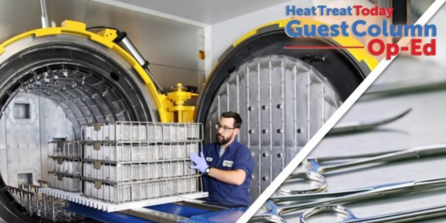
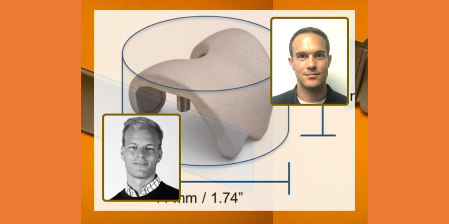
Medical devices, medical tools, and prosthetics all have a long history with heat treating. As we look to the future, the materials industry and the advancement of AM into the heat treat industry is moving at lightning speed.
In this article by Trevor Jones, CEO, Solar Manufacturing Inc., see why vacuum furnaces are excellent choices for accurately providing the necessary process parameters for this incredible medical technology that can provide people with mobility, function and independence to improve their quality of life.
This original content column was originally published in Heat Treat Today's Medical and Energy magazine, December 2020.
Trevor Jones CEO Solar Manufacturing, Inc. Source: Solar Manufacturing, Inc.
Thermal processing of metallic alloys is the backbone of the heat treating industry. Speaking of backbones, the human spine, a critical part of the human body, can now be replaced with an additively manufactured and heat treated prosthetic metallic alloy spine. Medical devices, medical tools, and prosthetics all have a long history with heat treatment. As we look to the future, the materials industry and the advancement of AM into the heat treat industry is moving at lightning speed.
AM parts require precise heat treating especially, when it comes to atmosphere control, temperature uniformity, and flexibility. Vacuum furnaces are ideal for accurately providing each of these process parameters. Let’s take a look at each of these heating treat parameters a little more closely.
Atmosphere Control
Vacuum, by nature, is a neutral atmosphere which, in part, means it has no carburizing or decarburizing potential. Therefore, the surface of the parts that is directly exposed to the vacuum atmosphere cannot gain or lose the base carbon content of the alloy. Additionally, vacuum is practically void of oxygen. If the parts were exposed to oxygen at the elevated processing temperatures, the surface of the parts would become oxidized. In minor cases, a superficial oxidation layer would be the result. In more severe cases, the surface could experience alloy depletion and diffused oxygen.
This is particularly important when processing titanium alloys, which are inherently more sensitive to carbon, oxygen, and nitrogen. When titanium is exposed to any of these elements, a metallurgical phase called “alpha case” can develop on the surface of the titanium and diffuse inwards towards the core of the part.
In most applications, the alpha case is undesirable, and precautions should be taken to prevent it.
Vacuum processing can also provide an atmosphere where an elemental substance, like nitrogen, can be kept in balance with the parts being processed. For example, if an AM part intentionally contains nitrogen, processing this part in a deep vacuum may remove some of the nitrogen base content in the part. To prevent this from occurring, partial pressure nitrogen in the vacuum furnace keeps the nitrogen in equilibrium. The surface condition of these parts is extremely important especially if the AM parts will be implanted into the human body.
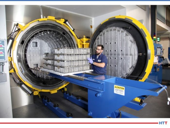
The medical processing room at Solar Atmospheres. Source: Solar Manufacturing, Inc.
Temperature Control
The working zone of the furnace encompasses the parts being processed. It is critical that this entire working zone volume be thermally uniform to achieve predictable and consistent results. If any area of a working zone is cooler or hotter than the temperature of another area, it may negatively impact the heat treatment results including difference in mechanical properties and dimensional changes of the parts. For example, if the process is stress relieving and the parts were not subjected to high enough temperature for the requisite time, the parts may still contain some residual stresses.
Residual stresses can have various negative consequences during manufacturing, including cracking and part distortion – during build and finish machining. Tensile residual stresses in finished parts can also reduce fatigue and corrosion performance.1 A failure of a medical implant in the human body would be disastrous if it could have been avoided with proper heat treating!
Medical Instruments Source: ??
With proper design, vacuum furnaces can provide very tight temperature uniformity of ±5°F with direct part temperature monitoring throughout an entire working zone over a broad temperature range.
Flexibility
The vacuum furnace is extremely versatile in the infinite amount of process variables that are available to be adjusted, including heating rates, soaking temperatures, soaking times, atmospheric conditions, and cooling rates. All these variables can be adjusted to provide precisely what is required for a given alloy to optimize the heat treatment needs for the part being processed. To meet the need of the modulus and the strength and fatigue characteristics of a medical implant, AM technology can adjust the mechanical properties of the implant by changing some of the parameters in the processing.2
One of the many steps in the AM process is heat treating, and vacuum furnaces provide the flexibility that can be tailored to the alloy and heat treatment required. Having an AM prosthetic custom vacuum heat treated to fit the human body, could be the key to its success.
Vacuum furnaces and their unique heat treatment processes are ideal for providing the atmosphere control, temperature control, and flexibility that are essential for AM medical devices, tools, and prosthetics. As the AM market expands and the technology advances, vacuum furnace technology will continue to be integral in fostering that growth.
About the Author:
Trevor Jones began his career as the project engineer at Solar Atmospheres commercial heat treating on their Research and Development Team, concentrating on the improvement of vacuum thermal processing equipment and the development of new processes. He is currently the CEO of the Solar Manufacturing, Inc., a division of the Solar Atmospheres Family of Companies.
GEBERIT Group, a European leader in sanitary products, will expand their annealing capabilities with two vacuum furnaces at their production plant in Ozorków. Both furnaces have larger working spaces than the standard: 900 x 900 x 1200 mm (HxWxL) to 900 x 900 x 2400 mm. These changes will allow the manufacturer to double the efficiency of the furnaces in one technological process.
As GEBERIT builds its independence by investing in heat treatment processes, some of the processes that they had carried out in traditional atmospheric furnaces will now be performed in these modern Vector vacuum furnaces supplied by North American SECO/VACUUM‘s parent company, SECO/WARWICK.
Sławomir Woźniak CEO SECO/WARWICK Source: secowarwick.com
“We chose the SECO/WARWICK Vector furnaces,” commented Mirosław Spasiński, head of the Technical Department of GEBERIT in Ozorków, “due to the guaranteed quality and efficiency but also the high cleanliness of the surfaces of the processed details, which is very important to us, as the elements are displayed in open GEBERIT sanitary installations, thus aesthetics play an important role.”
“An individual approach to the furnace design” notes Sławomir Woźniak, CEO of SECO/WARWICK Group, “is a project that requires expert engineering knowledge. [Our] engineers have the knowledge and experience that are needed to adjust the technology and its parameters so that it ensures the safety and failure-free operation of the device, but above all that the solution meets the expectations and needs of the client.”
Heat Treat Radio host Doug Glenn continues his conversation with AMS2750F expert Andrew Bassett. This final discussion revolves around changes in temperature uniformity survey (TUS) specifications.
Below, you can either listen to the podcast by clicking on the audio play button, or you can read an edited version of the transcript.
The following transcript has been edited for your reading enjoyment.
Doug Glen (DG): In this episode, Andrew Bassett and I have our third and final conversation about AMS2750F. Andrew Bassett is president of ATP and directly contributed his expertise to the latest revisions of AMS2750. If you haven’t heard the previous two episodes, you can find them by Binging or Googling Heat Treat Radio or by simply typing www.heattreattoday.com/radio into your browser.
In the first episode, you and I did some talking about just the AMS2750 generally; what it was, how it’s done, who was on the committee obviously, the fact that it’s not just a minor rewrite, but that it’s a major rewrite and then specifically in that first episode, we talked about thermocouples and calibration. Once we were done with that, we went into the second episode where we talked about system accuracy tests.
Andrew, again, tell our listeners who was involved on the committee. I know that from our perspective, the good folks over at GeoCorp had James LaFollete on the committee and I know Doug Shuler from Pyro Consulting was on there, but who else was on the committee that was responsible for putting this revision F together?
Andrew Bassett (AB): We had Marcel Cuperman from PRI (Performance Review Institute). He is one of the lead staff engineers for the NADCAP heat treat task group. We had Doug Matson from Boeing. Doug Matson, after the release of Rev F went into retirement. He has still been very active on any questions that have been arising with the Rev F. He’s retired, but he’s still in the loop with the specification. We had Brian Reynolds from Arconic. Again, we were looking for various people within the industry, so Brian Reynolds gave us a perspective from the raw material suppliers. We also had Cyril Vernault from Safran Aerospace. We wanted some European influence on the specification, and he is also the task group chairman for heat treat. We had a good, well rounded group of guys that were experts on this, to try to get this next revision put together.
DG: And yourself, of course. Let’s not forget that.
AB: I always like to say that I wrote the good stuff in there.
DG: Before we jump into TUS specifics and some of the major changes there, I want to hit just briefly on training. You and I were talking about this before we hit the record button. The fact of the matter is, there are several different training courses out there. Obviously, these three episodes ought to be helpful to you. A direct call to your cell or to Aerospace Testing and Pyrometry probably wouldn’t be a bad idea if somebody needed help with it. Does ATP also provide a training course?
AB: Yes, we do. We’ve always prided ourselves on providing AMS2750 training. Our training has always been customized to what our customers requirements would be, so every course is not the same. We like to take it to more than just AMS2750. You have to remember, there are other aerospace primes out there that have their own pyrometry requirements. For instance, GE Aviation has their own pyrometry requirements, P10TF3. Rolls Royce has their own pyrometry requirements. Or Pratt & Whitney might have some other things that need to be addressed. We actually sit down with our customers prior to any training and kind of take out the information that is needed, and then we perform the training onsite at the client’s facilities. So that if any other questions arise – “Hey, you’re talking about the SAT stuff” – then I can say, “Hey, let’s go for a field trip” and we can walk right out to the customer’s equipment and kind of demonstrate how to do, let’s say, a proper SAT or proper calibration. Again, we’ll cover various different specifications. For instance, one thing we like to do is find out what types of heat treating they’re doing. If they’re strictly a vacuum heat treating, I’m not going to talk about any of the aluminum requirements. There are some pyrometry requirements when it comes to aluminum, but we’ll talk about vacuum gauge calibrations, which is not covered under 2750, but is covered under AMS2769. Again, each one of our courses is customized to what our client’s needs are.
So, yes, they can feel free to reach out to us. There is myself and Collin Thomas who is an ex-NADCAP auditor for the two instructors for the course, and we’re more than willing to help out with that at any time.
DG: And just so everyone knows, at the end of this podcast, we will mention a couple of other companies and resources that you can go to for training on AMS2750F. I would like to mention, though, just a little self-serving note – and I did this with Google just a minute ago, though I don’t know that it will work on everybody’s location and what not… I Googled “AMS2750F” and Heat Treat Today came up as the second item with an article that we posted back on July 21st called AMS2750F expert analysis of which, Andrew, you were one of the contributors. We had five contributors, I believe, to that article, Doug Shuler being one of them, Peter Sherwin from Eurotherm being another, yourself being one and we had two others, Jim Oakes from SSI and Jason Schulze. I think you had to answer two or three questions and we compiled that. So that’s also a good resource to go to, if you have a moment to do so.
Let’s jump into temperature uniformity surveys (TUS). As we’ve done in the past, basically what we’re doing is asking you, “what were the major changes in this area?” So we’ve broken TUS into five basic questions. Let’s hit the first one now. Looking for the major changes in modifications and repairs section, tell us about that.
AB: In Rev E (the previous revision), there were two sections broken out called furnace modifications and furnace repairs. We put in there the caveat “but not limited to the following things.” If you replaced a hot zone in a vacuum furnace, or you changed thermocouple locations, these would trigger a major modification where you would have to do an initial uniformity survey. We basically took out the repairs function and just left in modification. If any kind of preventive maintenance, or some sort of maintenance function that is done, that would be considered a repair, it’s going to be up to the user’s quality organization to determine if any other testing is going to be required. For instance, if they replace a door seal around a door, quality is going to have to get involved and ask, “Do we need to do a uniformity survey?” What I always tell suppliers out there that are compliant with this is, get with your maintenance team, because the maintenance team typically will know whatever repair they did will have a major impact to maybe a uniformity survey. At that standpoint, repairs will have to be documented, as always, and then quality is going to have to sign off and ask, “Do we need another calibration, an SAT or a TUS?” We’ve put the onus back on the users now to determine if a test needs to be conducted. And then they’re going to have to defend that if they have an audit.
It was kind of silent in the previous revisions of the spec, but it was kind of mentioned that when you move a piece of thermal processing equipment from one corner of the building to the other corner of the building, that you were going to be required to do an initial uniformity survey. I brought up to the team, that these days, they actually make furnaces and ovens with wheels on them. This is for cellular manufacturing. If they have wheels on them to be moved to different locations, it again will have to be on the onus of the quality department to determine if another uniformity or initial survey needs to be done. Maybe they do a quick test on the furnace to make sure it’s within the same realm as the previous testing. We did say that initial TUS may be waived if the furnace is designed to be portable.
Some of the other major changes/modifications were people were always thinking if you changed your control thermocouple, when you replace it with a new one, that you have to do an initial survey. We always said no, you don’t have to do that as long as you put it back in the documented location. But I did see a problem with this when if they change the type of sensor, basically the thickness of the sensor. Maybe they went from a 3/16th sensor down to a 1/8th sensor. Well the 1/8th sensor is going to be more sensitive to temperature change and that could have a major impact on the uniformity. Or if they went from a hot junction that was not exposed to an exposed junction, this again increases the sensitivity. So we added in that as a major modification. If you do change that type of scenario on your thermocouples, then yes, you’d better do an initial uniformity survey.
And lastly, since we’re getting more and more advanced control systems, if you change the PLC logic, the PLCs that control a vacuum furnace or any other type of thermal processing equipment, then you better do an initial uniformity survey. So we kind of beefed up a little bit of the major modifications to address some of the newer technology that is out there.
DG: You said a lot of that was up to the quality department? Is that true, for example, when you went from a hot junction to not? Is that still up to the quality department?
AB: No. That’s now been changed under the major modifications that would trigger an initial uniformity survey. Changing from different types of sensors is not a repair, that is a modification.
DG: How about the way vacuum furnaces and the TUS’s need to be performed there? What were the major changes?
AB: There was really only one major change that we changed for when you conduct a survey on a vacuum furnace. Before, all you had to do was just do your typical uniformities within your temperature ranges for your qualified range of use and your vacuum pressure. If you had a diffusion pump, it had to get below one micron and then just do your survey. But then, I think it was Dr. Shuler, that brought up the idea that said, if people use a back fill gas or use partial pressure, maybe they just need to have one test under partial pressure.
At first, we got a lot of push-back from the suppliers on that saying this is going to cost them extra money and they would have to do an extra test. And we said, no, this is just part of your routine temperature uniformity survey schedule. We’re just saying, at least on an annual basis, you choose a single operating temperature within a defined partial pressure range that you use during production. We just want a survey done that way. You get to choose what gas you’re using, if you’re using argon or nitrogen. The thought process behind this was, if you had a needle valve that maybe was leaking and creating a cold spot in your furnace and you didn’t know about it, it’s more of a preventive thing to ask are those needle valves leaking and are you getting a cold spot in your furnace that you don’t know about. That’s all we’re asking, is just for one survey to be done in any one of your single set point temperatures with any partial pressure gas in the range that you define as your partial pressure. Once we explained it that way, we were able to get over that hump and move forward.
DG: It wasn’t as onerous as it initially sounded, apparently.
AB: Yes, I think the wording in the original draft sounded like it was going to be an extra survey, and I can understand the pushback from the suppliers. We explained that it was not an extra survey, it’s just one during your regular routine survey.
DG: Right. It replaces another one.
AB: Correct.
DG: Question 3. Location of the test thermocouples when you’re under 3 cubic feet.
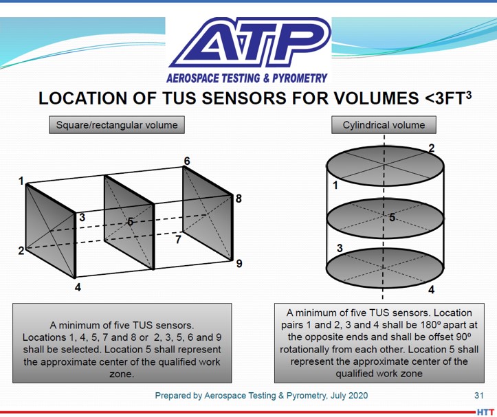
AB: This was something that I always had an issue with in AMS2750, in the previous revision. How it was stated was that when you have a furnace less than 3 cubic feet, you can do a survey with five sensors. And it said that the five sensors shall be placed in the corners. Well, in a cylindrical furnace, you have eight corners, so what five corners do you choose? My understanding was that when NADAP PRI was teaching their pyrometry course, it was basically the central plane of the furnace. So you would have two thermocouples in the front that were in the center plane and then two in the back in the center plane and one in the center.
And I said, that doesn’t really work so well because you’re not really getting what’s on the top of the furnace or the bottom of the furnace. So, what we ended up doing was putting some new diagrams in the specification that showed that you’re going to go opposite corners. Let’s say you’re going to put one thermocouple in the top left corner in the front and then diagonally across from that will be one in the bottom right corner. Then in the back you would reverse those. So we are covering the top and bottom of the furnace. And the last thermocouple will be in the center. We spelled out a little bit better way of testing these smaller furnaces.
Source: ATP
In a cylindrical furnace, it is stated that those thermocouples should be 180 degrees apart. Again, the NADCAP course would basically put five thermocouples in the center plane of a cylindrical furnace. And we said, no, we want two thermocouples on the top directly 180 degrees apart from each other and then two on the bottom, again, 180 degrees apart from each other, but they should be offset 90 degrees from the top one. You’re getting a better test of your full work zone dimension. I’ve always been doing these testings with these small furnaces in this method because that’s actually an older requirement from an old Boeing specification; the old BAC5621 actually spelled it out this way. We kind of adopted the old Boeing requirement of the smaller furnaces to show a better test for your small furnaces now.
Source: ATP
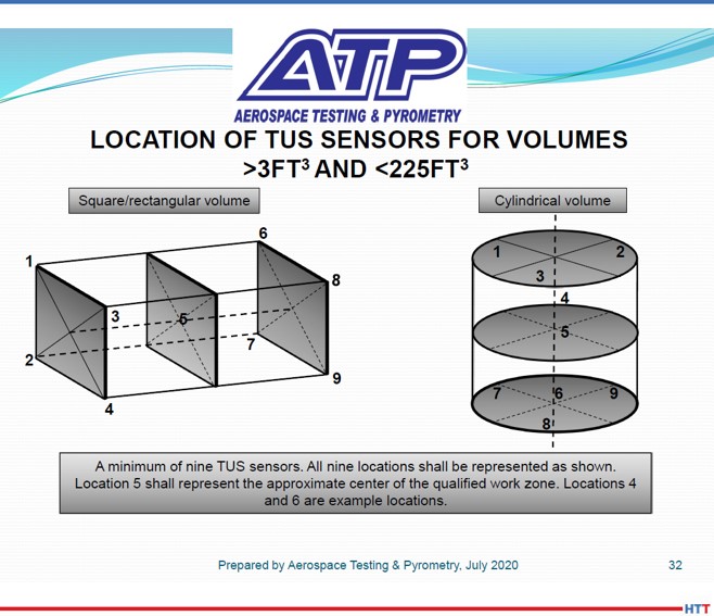
DG: Right. And let’s be clear, that is for a 3ft3 or smaller furnace. I assume, over 3ft3, you’ve still got nine thermocouples.
AB: Yes, greater than 3ft3 and less than 225ft3, you’ve still got the nine sensors. Once you get above 225 ft3, then the formula is in place in 2750F that spells out how many more thermocouples. I believe we don’t allow it to go past 40 thermocouples in some of those big monster furnaces.
DG: Let’s talk about aluminum for a little bit here. We’ve got radiation test surveys in aluminum furnaces, anything above 800°F; let’s talk about that.
AB: This is actually a surprise that this didn’t get some more pushback when we were putting the drafts out there. Originally, in previous revisions, it said all aluminum solution heat treating furnaces where the heat source is located in the wall, you had to do what’s called a radiation test survey. But we’ve changed the requirement to say all aluminum alloy thermal processing equipment used above 800, also with the heat source located in the furnace wall, ceiling or floor. This is a game changer because this will now put those aluminum vacuum braze furnaces into play. This was typically only a requirement for solution heat treating of aluminum alloys, but now it’s going to be for aluminum brazers. I’m very curious of how this is going to work. A radiation test survey is basically you have to have one 6061 aluminum panel that is 12 inches square with a test thermocouple peened into the middle of it and there is one panel for every 10 cubic feet of wall area. Basically, what we’re looking for is if there is any kind of direction radiation of heat to an aluminum panel as your panels are going to get extremely hot. What they’re looking for is eutectic melting. All aluminum heat furnaces, it’s required by AMS2770 which is the aluminum processing spec that says if you’re processing aluminum, there can’t be any direct radiation to the parts. But in a vacuum furnace, how is it heated? Direct radiation. I’m very curious as to how this is going to play out for those suppliers. Again, I was really surprised there wasn’t a whole lot of pushback from the aluminum vacuum braze facilities that have these types of furnaces that are now going to be required to do this test. It’s going to be interesting how that plays out once 2750 is in full force for everybody.
DG: Yes, and I guess we ought to say that it is not always radiation in a vacuum furnace. If you don’t have back fill gases, ok, it’s going to be all radiation. But if you’ve got some convective heat going on with back fill gases, that is possible. It doesn’t change the point that we’re making here. This is something for people to be aware of if you’re working with a vacuum furnace above 800°F, you’re doing any type of aluminum, then you’ve got a new requirement to do this radiation test.
AB: Yes. It’s the change of the words of ‘solution heat treating’ to ‘all aluminum alloy thermal processes.’
DG: Last question of the five. Documentation requirements. You mentioned there have been some changes. Tell us about those.
AB: We made a few changes to the documentation requirement. Basically from the standpoint of Rev E, we left everything from the original requirements in there, but people were unfamiliar with right after the section that talked about documentation. (The funny thing is we had to change it from reports to documentation. There was somebody that said we don’t want to call it a report because that quantitates that it has to be all in one package, we want to call it documentation. So we appeased that one.) Anyway, in Rev E, it was not part of the documentation records, but should be accessible on site, which were the control instrument tuning parameters, the PIDs or the proportional band reset rate, depending on the instrument manufactures, that those had to be documented for each thermal processing equipment. We thought this is being missed. There are a lot of places that I’ve been to where they don’t even know what the tuning parameters are. So we said from now on you’re going to have to document that in your TUS reports.
It also required to have a diagram of your TUS thermocouple location. That has always been a requirement, but we also now require you to show where the control thermocouple is placed and if you have any recording sensors. If you have type A instrument A or C instrumentation to have the high and low, those would have to be denoted on the diagram for part of the documentation package. We want to make sure that the supplier is aware that we don’t just need to see where your nine thermocouples are located, we also need to see where the control is and any applicable other sensors in the furnace that qualify for A, B or C.
We also want to find out, too, what type of atmosphere is being used in the furnace. Is it air? Is it a vacuum? Are you putting it under carburizing? You now have to list the atmosphere that was done during the testing as well. And then we’re also saying that the TUS test instrument that you’re using, you have to let us know what the correction factors are, even if you electronically apply them to the TUS instrument. You’re allowed to put in the correction factors prior to starting the TUS for your test instrument. A lot of people are saying it’s already been put into the recorder, I don’t need to document it. But we’re saying we still need to know what that correction factor is. So you need to document what those correction factors are.
There are two other things that are new to the documentation requirements. If you have types A or C instrumentation, again with the hot and cold thermocouples placed in there from the last uniformity survey, there shall be an analysis done to make sure that those locations have not changed. There are some requirements in Rev F that say if your uniformity survey is half your uniformity tolerance. In other words, if you’re testing for ∓10 and your final results come out less than ∓5, you can make an easy statement that my survey is within ∓5. No relocation of my hot and cold sensors are required. But you have to do an analysis of those two sensors for types A and C.
[blockquote author=”Andrew Bassett” style=”1″]We also want to find out, too, what type of atmosphere is being used in the furnace. Is it air? Is it a vacuum? Are you putting it under carburizing? You now have to list the atmosphere that was done during the testing as well.[/blockquote]
The other change deals with more of shaker type furnaces or continuous type furnaces, we call them continuous or semicontinuous furnaces. You have to list out what the traversing speeds are during your uniformity survey, maybe whatever your bump rate is for your shaker or the traverse rate. Then you’re going to have to recalculate what your work zone is. With a continuous type furnace, obviously your work zone will shrink the faster the belt goes through the furnace. There needs to be a recalculation of the work zone dimensions based on the survey based on what the belt speed should be.
And then lastly, like we’ve done with all the other documentation, if your service is being performed by a third party, the quality organization of the third party must also approve the reports as well.
Those are the major changes when it came to the documentation for temperature uniformity surveys.
DG: Basically, we’ve hit on three major areas. The first episode – thermocouples and calibration, the second episode – system accuracy tests, and this episode – temperature uniformity surveys. Are there any other odds and ends that you think our listeners should know about?
AB: Absolutely. There are a couple last minute things towards the end of this specification that already passed all the testing requirements.
The biggest pain when it came to Rev E is that we had the requirement for rounding, and that was to the ASTME29 method. That caused a lot of problems. I think we put a number on all the thermocouple suppliers because typically the thermocouple suppliers – when they’re doing their calibration of thermocouples – put everything into Excel. Well, Excel rounds .5 up, like we all learned in grade school. But, E29 doesn’t like that. They like to have if your next significant digit is odd, it rounds up; if it’s even, it stays the same. That put a little hamper on all of the thermocouple guys and we kind of didn’t think that one through.
So, now we’ve changed it in Rev F. The methods that you can use are ASTME29 using the absolute method, that still can stay the same, or you can use an equivalent international standard such as ISO 8001 rule B which is .5 round up, or you round to any commercial spreadsheet, in other words .5 round up. As long as you have documented procedures and you have to use it in a consistent manner. I should say we’ve relaxed the rules, so now you can choose what kind of rounding method you want to use.
We wanted to make sure that we spelled out, too, that all the tolerances in 2750F, if you look at Rev F compared to Rev E, all the tolerance requirements, we used to say plus or minus 10, now it says plus or minus 10.0. It’s an absolute. If you have a survey that you do that is 10.2 and you want to try to round that down, you can never round anything back into compliance. If something does fall out of tolerance by a 10th of a degree, or whatever, you cannot using the rounding function to bring it into compliance.
We addressed a hole that was left in Rev E on your test interval extensions. In previous revisions, we forgot about adding bimonthly and every four months, how many days you can go past an extension for a due date, so we finally addressed that in this revision. It used to be Table 10 and now it’s Table 25. The only thing that’s added onto this is if you do use an extension for any reason, there must be a written justification approved by the user’s quality organization. It can be as simple as: my test came due on Sunday, but I came in and did the test on Monday. You’re just going to have to write a note saying the due date was Sunday and you did it on Monday. You just have to write some justification of that.
Lastly, and I think this is a big thing, as well, is under the quality assurance provision. It is basically the section that says what happens if you have a pyrometry failure and so on. We didn’t change anything in there except two years after the release of Rev F, any third party pyrometry service organization must have a quality system approved to ISO 17025. Also, the scope of accreditation shall include laboratory standards and/or the field services applicable.
Third party service providers, two years after the release, will now have to be 17025 accredited. If they are, there is also no procedural oversight from the supplier. For example, since we’re 17025 accredited for our laboratory, we actually hold two different accreditations, one for our laboratory and one for our field service work for calibrations for uniformity surveys and system accuracy testing. Now, since we are third party accredited, our clients will not be required to have any oversight on us. Personally, I don’t think that’s the best option; I think the supplier should still be able to audit us and look at our procedures to make sure it’s compliant with the industry standards. But according to Rev F, there is no more oversight if we’re third party accredited.
I wasn’t a big fan of adding this in. Again, you would think people that are 17205 like ourselves would be happy to have this in there as it might weed out some other companies, but I’ve actually worked with some really good smaller shops – a two-man father and son that’s located in New York, and then a gentleman in California that is just a single guy, and these guys are very versed in the specification and do thing right. Unfortunately, now they’re going to have to be 17025 accredited. I talked to one of them and he said, “This may put me out of business. I don’t know if I can afford swinging this. I do a good job.” And I said, “I know, I’m trying to fight for you on this,” but it ended up going in. At least we put the caveat that they have two years to get it down, so it’s not something immediate.
DG: Yes, that is the danger when you start requiring certain accreditations, licenses or whatever. It’s typically the small guy that takes the beating. That’s too bad, but that’s the way it is… I shouldn’t be so flippant about that, should I? It is too bad!
AB: I really struggled. Originally, the first draft was going to be immediately, and I said, no, let’s put a moratorium on it for at least two years so people can queue up for that.
DG: I guess the moral of the story for the end user is within two years you need to be asking your third party survey companies/accreditation folks, whoever is coming in to do your pyrometry and whatnot, if they have this 17025.
Anything else? Any other odds and ends?
AB: The last thing I want to add about the 17025 is that this is only for third party suppliers. We’ve received questions like, We do our pyrometry internally, do I have to go get 17025? No, you don’t. It’s only for third party suppliers.
DG: Let’s wrap up with a couple of quick things here. Training. If there are listeners out there who want additional training. We talked at the beginning of this episode about what Aerospace Testing and Pyrometry, your company Andrew, what you guys can do. I’m going to list a couple of other places, I believe, have training, and then if you know of any others you’re comfortable mentioning, please feel free to do so.
I do know, you mentioned, PRI does some sort of training here on this. I believe, a good friend of Heat TreatToday, Jason Schulze up at Conrad Kacsik, have something, and I’m sure they can do custom. I don’t know if they have standard courses or not, but I’m sure they can do some custom stuff. And, I believe that Super Systems also has some sort of training on this. I believe GeoCorp does, or will. But those are the only sources I know. Correct me if I’m wrong on any of those and let me know if there are any other places that people could get training.
AB: I wasn’t familiar with Super Systems or GeoCorp, but everybody is getting onto this bandwagon. But the other course I would also know of is Doug Shuler’s Pyro Consulting as well. He does teach an advanced pyrometry course.
DG: First of all, Andrew, we really appreciate your time doing these three episodes. If people want to get a hold of you, what are you comfortable giving out? We don’t want to give out your cell phone, unless you’re comfortable with it, but certainly emails and things of that sort.
AB: They can give me a call on our office line which is 844-828-7225. If you press 1, that’s supposed to actually ring my cell phone, but sometimes it doesn’t and sometimes it does. You can try the office line or you can reach me through email which is abassett@atp-cal.com or you can hit us up on the website www.atp-cal.com and you can just hit one of the emails of support and let me know what you’re looking for from pyrometry training, or anything else for that matter, and I’ll be more than happy to reach out to you.
DG: If you’re interested in reaching out to Andrew, please try the above. Of course, I’m always willing to take emails and put you directly in touch with Andrew, if you’d like. You can do that by emailing doug@heattreattoday.com.
Doug Glenn, Heat Treat Today publisher and Heat Treat Radio host.
To find other Heat Treat Radio episodes, go to www.heattreattoday.com/radio and look in the list of Heat Treat Radio episodes listed.
Derek Dennis President Solar Atmospheres California Source: solaratm.com
West coast heat treater Solar Atmospheres of California (SCA)recently added additional large furnace capacity to their inventory of vacuum equipment. The furnace was specifically designed to process a variety of materials that require optimum performance during controlled heating and cooling, vacuum processing, positive pressure processing, and differential pressure processing.
Key equipment characteristics include 84” x 144” all graphite and CFC hot zone, temperature uniformity ±10°F, 2-bar high performance 800 HP cooling system. Additionally, the furnace has a maximum operating temperature of 2650°F and a maximum loading capacity of 50,000 lbs. SCA worked closely with sister company, Solar Manufacturing, to design and fabricate the equipment to meet all prime requirements and AMS 2750 standards.
“We are very pleased to add the additional large furnace capacity,” SCA President Derek Dennis states. “Each new furnace installation is built on a building block approach from the personal knowledge and experience accumulated by operating previous furnace models. I really appreciate the ability to bounce different ‘out of the box’ ideas to our manufacturing team, who then takes those ideas and makes them a reality. Often, the team takes the ideas to another level before the final build plans go to the shop floor.”
Magnus Ahlfors Applications Engineer – Hot and Cold Isostatic Pressing Quintus Technologies AB
Chad Beamer Applications Engineer – Hot and Cold Isostatic Pressing Quintus Technologies LLC
I’m sure we all know someone, or you may be that someone, who has had a knee or hip replacement. It seems to be commonplace today to have reconstructive joint replacement.
In this Technical Tuesday article by Magnus Ahlfors, Applications Engineer and Chad Beamer, Applications Engineer both in Hot and Cold Isostatic Pressing at Quintus Technologies LLC, explore new developments within hot isostatic pressing (HIP) that can offer opportunities to improve the performance and quality of the implant, while cutting production costs and lead times.
This Original Content article will be released in the upcoming Heat Treat Today Medical and Energy magazine this December 2020. Check here after December 14, 2020 to look at the digital edition.
Introduction
The development of new production technologies over recent years has brought a range of possibilities to manufacturers of orthopaedic
implants for reconstructive joint replacement. Old truths have been challenged, and new ways to increase product performance, quality and cost efficiency introduced. Additive manufacturing (AM) is one of the technologies that have added new flexibility and value in implant manufacturing and is now an important manufacturing method for orthopaedic implants. Perhaps less known is the development within equipment for hot isostatic pressing (HIP) that offers great opportunities to improve the performance and quality of the implant, while cutting production costs and lead times.
Hot Isostatic Pressing of Orthopaedic Implants
Orthopaedic implants are commonly manufactured by casting and additive manufacturing. Metal injection moulding (MIM) is also widely used for dental implants. Implants manufactured by these technologies will contain internal defects such as shrinkage and gas porosity, lack of-fusion between layers and residual porosity after sintering. These internal defects will act as stress concentrations and crack initiation points in the material, which will negatively influence the material properties.
Figure 1. Defect elimination by HIP for E-PBF Ti-6Al-4V [8] (Photo source: Quintus Technologies)Hot isostatic pressing uses a high isostatic gas pressure, up to 207 MPa (30,000 psi), and elevated temperature, up to 3632°F (2000°C), to eliminate these internal defects and achieve a 100% dense material. The elimination of defects results in improved fatigue properties, ductility, and fracture toughness.1-7 For this reason, HIP is widely used for orthopaedic implants like hip, knee, spine, ankle, wrist as well as dental implants to ensure quality and performance and prevent early failure of the implant inside the patient. Common materials are cobalt-chrome alloys like ASTM F75, titanium alloy Ti-6AL-4V, and stainless steel 316L. The densification by HIP for additive manufactured (E-PBF) Ti-6Al-4V is shown in Figure 1 where a printed coupon has been analyzed with X-CT before and after HIP.
New Possibilities with Additive Manufacturing
Developments within additive manufacturing of metal parts have opened up possibilities for patient-specific orthopaedic implants where the implant is tailor-made based on X-ray imaging of the patient for a perfect fit. AM makes patient-specific implants economically viable since there is no tooling such as casting moulds or forging dies; therefore, it is easy to make new unique designs without adding significant cost and lead time to the production process.
Patient-specific implants offer many benefits to the patients and doctors, including better fit to the existing bone structures, shorter surgery times, faster recovery times, and less risk of implant loosening inside the patient.9 The demand for patient-matched implants produced by AM is growing steadily and is predicted to accelerate as production costs are coming down. A fundamental change with personalized implants is that there is no possibility for the healthcare system to stock implants since every implant is unique and made to order. This results in shorter lead times in getting the implant made, which is very important because that is also the wait time for the patient. Minimizing the lead time for the different steps in the manufacturing process, including HIP and heat treatment, is a huge driver.
Optimized HIP and Heat Treatment for AM
The nature of the additive manufacturing process is quite different from conventional casting and forging manufacturing resulting in different microstructures in the as-manufactured condition. For example, the solidification and cooling rates in powder bed fusion (PBF) are several thousand degrees per second, while the casting rate can be a few degrees per minute resulting in microstructural differences even for the same alloy. Despite the differences, most HIP and heat treatment protocols used for AM parts today are developed for cast and wrought material and might not be optimal for AM material. One reason is that these traditional standard HIP protocols are often the only option available in industry today, like at a HIP service provider.
Figure 2. Quintus® QIH48 HIP system (Photo source: Quintus Technologies)
Studies have shown that there is potential to achieve significant improvements in material properties when optimizing the HIP process specifically to AM material. One example is presented in Optimizing HIP and Printing Parameters for EBM Ti-6Al-4V, HIP1710 where an optimized HIP cycle for E-PBF Ti-6Al-4V was investigated as an alternative to the traditional cycle used in industry today of 1688°F, 14.5 ksi (920°C, 100 MPa) and 2 hours soak time. In this study it was found that a modified HIP cycle with lower temperature and higher pressure gave significantly higher yield and tensile strength with retained ductility compared to the traditional HIP cycle. A similar study presented in Evaluation of HIP-Parameter Effects on AM Titanium Ti-6Al-4V 11 shows that that the modified HIP cycle with lower temperature and higher pressure also leads to improved fatigue properties compared to material treated with the traditional HIP cycle for L-PBF Ti-6Al-4V.
A New Era of HIP Equipment
A lot of developments and improvements have been made within equipment for hot isostatic pressing in recent years. A modern HIP system today is space and cost effective and easy to operate and maintain. Quintus Technologies offers HIP systems in a variety of different sizes suitable for a wide range of production volumes. Such product offerings enable the appropriate fit for many business cases.
One important innovation within HIP technology is the rapid cooling capability available in Quintus® HIP systems (Figure 2). The high cooling rates are achieved by a forced convection cooling of the highly pressurized argon gas in the HIP process with a maximum cooling rate up to 7200°F/min (4000°C/min).
Rapid cooling significantly shortens the HIP cycle time since the cooling segment of the cycle takes minutes instead of several hours as compared to a conventional HIP system. This makes the modern HIP system very productive with a lower initial capital expenditure because smaller HIP units can handle higher throughput.
Combining HIP and Heat Treatment
Fast cooling and quenching directly in the HIP system also make it possible to perform many conventional heat treatments for metals, allowing for integrated heat treatment with the HIP cycle.
The main purpose in combining HIP and heat treatment is to eliminate process steps to achieve a shorter and more cost-effective post processing. In Figure 3a, a schematic visualization shows how conventional thermal post processing for a cast, AM or MIM implant, could look when the thermal treatments are performed separately. These steps are often performed in different equipment and sometimes even at different physical sites.
The possibility to do rapid cooling and quenching in the HIP system enables the combination of the HIP and solutionizing step to be performed at the same time in the HIP furnace. Other potential steps such as stress relief, aging, or tempering can also be incorporated into the HIP cycle. In Figure 3b, a potential combined post processing route is shown for the same case as shown in Figure 3a.
When more process steps can be included into the HIP cycle, the total processing and production lead time is reduced. The transfer operations between different steps, for example, from the HIP to a vacuum furnace, are also eliminated saving time and cost. Another benefit is that energy consumption can be reduced by running the combined process, since the parts don’t have to be heated up and cooled down as many times. When combining the HIP and solutionizing step, as seen in Figure 3b, the time at the elevated temperature for the implants can be significantly reduced; that means that potential grain growth during the post processing can be minimized, which is often desired.
HIP and Heat Treatment of CoCr ASTM F75
A good example for combined HIP and heat treatment is cobalt chrome alloy ASTM F75, which is a common material for orthopaedic implants. This material is prone to form carbides during the processing that have a detrimental effect on the mechanical properties.12 The standard HIP cycle for this material is 2192°F, 14.5 ksi (1200°C, 100 MPa) with 4 hours soak time, and at these conditions the carbides will dissolve. However, the carbides will form again during the cool down from the HIP temperature unless the cooling is done fast enough to prevent reprecipitation. The minimum cooling rate required to avoid precipitation of carbides during the cool down is around 360°F/min (200°C/min), according to standard ASTM F3301-18.
Since conventional HIP systems without rapid cooling capabilities will cool much slower than 360°F/min (200°C/min), the material will contain these detrimental carbides after HIP. To correct this, a homogenization or solution anneal treatment is added after the HIP step. Treatment parameters typically consist of a soak at 2192-2246°F (1200-1230°C) for 4 hours in a vacuum furnace where the minimum cooling rate can be achieved. Therefore, the parts are moved to a different type of furnace and heated up to the same temperature and soak time as the HIP process with the sole purpose to achieve a high enough cooling rate to obtain the desired microstructure and properties.
Thanks to the rapid cooling in a modern Quintus® HIP system, ASTM F75 components instead can be cooled directly in the HIP system at a high enough rate to avoid carbide formation and thereby completely eliminating the need for a separate homogenization/solution treatment. The result is that only one thermal treatment is needed instead of two, one piece of equipment needed instead of two, and the material will spend 4 hours at elevated temperature instead of 8 hours, which is beneficial. This is applicable on both cast and AM implants as well as MIM.
Figure 4. Size of femoral knee implant used for case study (Photo source: Quintus Technologies)
The Productivity of a Modern HIP System
The rapid cooling capability of these systems lead to a significant reduction in the HIP cycle time and thus, improved productivity of the production chain. To demonstrate the high capacity of these HIP systems, a production case is presented below where two Quintus® HIP systems, the QIH15L and the QIH48, have been compared.
For this case study, a femoral knee implant made of ASTM F75 has been chosen. The size of the implant can be seen in Figure 4 represented by a cylinder. It is assumed that the implants are not allowed to be in contact with each other during the HIP cycle, so it calculates how many cylinders can fit in each furnace, making the calculation conservative. The HIP parameters for this case are 2192°F, 14.5 ksi (1200°C, 100 MPa) and 4 hours with rapid cooling, which will determine the HIP cycle time. The production conditions in this case are chosen to be 24 hours/day, 5 days/week and 48 weeks/year with a 90% uptime of the HIP system. All input data is summarized in Table 1 and the results are presented in Table 2.
As can be seen in Table 2, the QIH15L can process 58,300 implants per year while the QIH48 can produce 611,200 in the same time frame. These numbers are quite high considering these two HIP models belong to the Quintus® Compact HIP series and are relatively small units aimed at in-house production lines. The HIP cycle time is around 8 hours and the larger HIP system, the QIH48, has a slightly longer cycle time compared with the smaller QIH15L. This cycle time is calculated with the assumption that rapid cooling is used. If a conventional system without rapid cooling is used instead, the total HIP cycle time can be as much as twice as long, close to 16 hours total, showing the impact of the rapid cooling capability on system productivity. Of course, this would be reflected in half the number of parts per year. A more comprehensive productivity and cost analysis for modern HIP systems have been made in Cost-Effective Hot Isostatic Pressing – A Cost Calculation for MIM Parts.13
The Benefits of Insourcing the HIP Process
Traditionally, most orthopaedic implant manufacturers have been outsourcing the HIP process to external HIP service providers rather than having the HIP process in-house, and that is still the situation today. A benefit of using a HIP service provider is that it is a cost-effective alternative even for relatively small annual volumes. This is possible since the service provider can consolidate different lots from different customers together in one HIP cycle, so called coach cycle, making it a cost-effective route.
However, insourcing the HIP process is becoming more interesting and some implant manufacturers have already invested in HIP equipment to facilitate the HIP process in-house. One reason for this trend is the strong technical development of the modern-day HIP equipment, as already discussed in the previous chapter.
Insourcing the HIP process has several positive aspects and some are discussed here below:
Shorter production times – Since the time of transport to and from the service provider is eliminated along with the turnaround time at the service provider, the lead time for HIPing the implants can be significantly reduced. When HIP with in-HIP heat treatment capability is fully integrated into the production process, process steps can be eliminated and time waste can be minimized.
Eliminate risks – Since the transporting to and from a service provider is eliminated, so are the risks related to transport delays and damaged/lost goods.
Production flexibility – Full control over the production schedule and lead times result from the flexibility to run cycles when needed and possibly to fast-track time-critical deliveries through the internal schedule. This can be important for patient-specific devices where short lead time is always a requirement.
Control over quality and process improvement – With the full HIP and heat treatment process in-house, the quality system can be further developed to avoid mistakes and non-conformities, while good-receipt inspection can be minimized. Typical issues can include loss of implant traceability, parts being treated with the wrong HIP parameters, and surface contamination such as surface oxidation and alpha casing etc. Internal know-how and expertise on how to run the HIP process will be developed over time to avoid quality issues and delays, all with the help of the Quintus Care® program.
Optimized HIP and HT protocols – When operating the HIP process in-house, one is not limited to the standard coach cycle generally offered by the HIP service industry. Instead, the HIP process can be tailored for the needs and requirements of specific parts and materials made by casting, AM, or MIM to achieve maximum performance and quality of the implants. This possibility is extra important for parts produced by additive manufacturing (AM) since optimized HIP cycles, specifically for AM material, can result in significantly improved material properties compared to the standard HIP cycles as has been shown. Opportunities include integrating different heat treatments into the HIP cycle that are enabled by rapid and steered cooling to achieve the most effective production route, facilitating in-house R&D to continuously improve HIP processing, and optimizing for new products and applications. Today, there are HIP service providers on the market who have modern HIP systems with rapid cooling capabilities that can also offer optimized cycles and combined HIP and heat treatment.
Lower total production cost – Having a high utilization rate on an in-house HIP system yields the lowest operating cost for the HIP process. The cost for heat treatment can potentially be eliminated completely if the combined HIP and heat treatment approach can be used. Since transportation to external sub-contractors can be avoided, the cost of transportation is eliminated as well as the cost of insurance during transport. There are also potential indirect cost savings from improved quality control routines, more flexible planning, and shorter delivery times.
So, overall control of the process when operating in-house is one of the key benefits when coupled with better properties of the implants, short lead times and low cost for the process.
Conclusions
In this paper we have discussed the development of modern HIP technology such as the possibility to perform rapid and steered cooling directly in the HIP, which gives a significantly improved production capacity of the HIP system. The rapid cooling capability of modern Quintus® HIP systems also makes it possible to include heat treatment processes directly into the HIP cycle with the purpose of eliminating process steps for shorter lead times and more lean production.
AM is growing as a production method for orthopaedic implants with a potential for modifying and optimizing the HIP cycles for AM-produced components. Such optimized approaches offer a product with enhanced material properties compared to traditional HIP cycles, which were often developed for cast and wrought material.
The advantages of operating the HIP process in-house include minimal lead time, control over quality, process improvement, flexibility in production planning, the possibility to use optimized HIP cycles, and a lower total production cost from direct and indirect cost savings.
References
[1] JJ. Lewandowski and M. Seifi, Metal Additive Manufacturing: A Review of Mechanical Properties, Annual Review of Materials Research 46, pp. 151-186, 2016.
[2] J. Kunz et al., Influence of HIP Post-Treatment on the Fatigue Strength of 316L-Steel Produced by Selective Laser Melting (SLM), Proceedings WorldPM2016, Oct. 2016, Hamburg, Germany.
[3] S. Leuders et al., On the Fatigue Properties of Metals Manufactured by Selective Laser Melting: The Role of Ductility, J. Mater. Res. 29, 1911–1919, 2014.
[4] N. Hrabe et al., Fatigue Properties of a Titanium Alloy (Ti–6Al–4V) Fabricated Via Electron Beam Melting (EBM): Effects of Internal Defects and Residual Stress, International Journal of Fatigue vol. 94, pp. 202–210, Jan. 2017.
[5] J. Haan et al., Effect of Subsequent Hot Isostatic Pressing on Mechanical Properties of ASTM F75 Alloy Produced by Selective Laser Melting, Powder Metallurgy vol. 58 no. 3, pp. 161–165, 2015.
[6] V. Popov et al., Effect of Hot Isostatic Pressure Treatment on the Electron-Beam Melted Ti-6Al-4V Specimens, Procedia Manufacturing, vol. 21, pp. 125-132, 2018.
[7] R. Kaiser et al., Effects of Hot Isostatic Pressing and Heat Treatment on Cast Cobalt Alloy, Materials Science and Technology, Vol. 31, No. 11, Sept. 2015.
[8] S. Tammas-Williams et al., The Effectiveness of Hot Isostatic Pressing for Closing Porosity in Titanium Parts Manufactured by Selective Electron Beam Melting, Metall. Trans., Volume 47, Issue 5, pp 1939–1946, May 2016.
[10] M. Ahlfors et al., Optimizing HIP and Printing Parameters for EBM Ti-6Al-4V, HIP17 – 12th International Conference on Hot Isostatic Pressing, Dec. 2017, Sydney, Australia.
[11] T. Kosonen and K. Kakko, Evaluation of HIP-parameter Effects on AM Titanium Ti-6Al-4V, AeroMat19, May 2019, Reno, Nevada.
[12] M. Chauhan, Microstructural Characterization of Cobalt Chromium (ASTM F75) Cubes Produced by EBM Technique, Master Thesis at Chalmers University of Technology, 2017.
[13] M. Ahlfors et al, Cost-Effective Hot Isostatic Pressing – A Cost Calculation for MIM Parts, Metal Injection Molding International, Vol 12 No. 2, June 2018.
About the Authors:
Magnus Ahlfors works as application engineer in hot isostatic pressing where he is heavily involved in the development and optimization of HIP processes for different industries, especially for metal additive manufacturing. Magnus has a MSc in Materials Engineering from Chalmers University of Technology, Sweden and has worked at Quintus Technologies since 2013.
Chad Beamer has a MS from the Ohio State University in Material Science and has worked as a material application engineer with GE Aviation years and as a technical services manager with Bodycote. In February, Chad began working with Quintus Technologies as an applications engineer for the Advanced Material Densification division focusing on hot isostatic pressing (HIP). As an applications engineer, he manages the HIP Application Center located in Columbus, Ohio, educates on the advancements of HIP technologies, and is involved in collaborative development efforts both within academia and industry.
Heat treater ALP Aviation is increasing its production capacity and expanding process capability with a vacuum furnace. The furnace is dedicated to low pressure carburizing of transmission components for helicopters and other aircraft.
Sławomir Woźniak CEO SECO/WARWICK Source: secowarwick.com
The new vacuum furnace is configured with horizontal charge loading, a maximum cooling gas pressure of 15 bar of argon and nitrogen, and a 900mm x 900mm x 1200mm (W x H x L) charge area.
This Vector vacuum furnace is the heat treater's 4th installation in a 13-year cooperation with SECO/WARWICK, the parent company of North American-based SECO/VACUUM. "Our 13-year relationship with ALP AVIATION continues to be of mutual benefit on all technical and managerial levels," says Sławomir Woźniak, CEO of SECO/WARWICK Group. "[We provide] the technology, equipment and process knowledge which has enabled our client to grow their business. Our Group values working close to the customer."


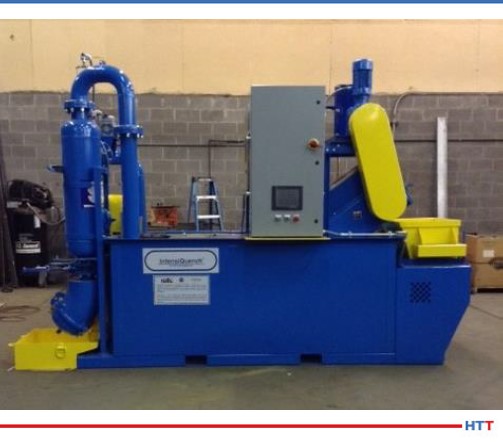
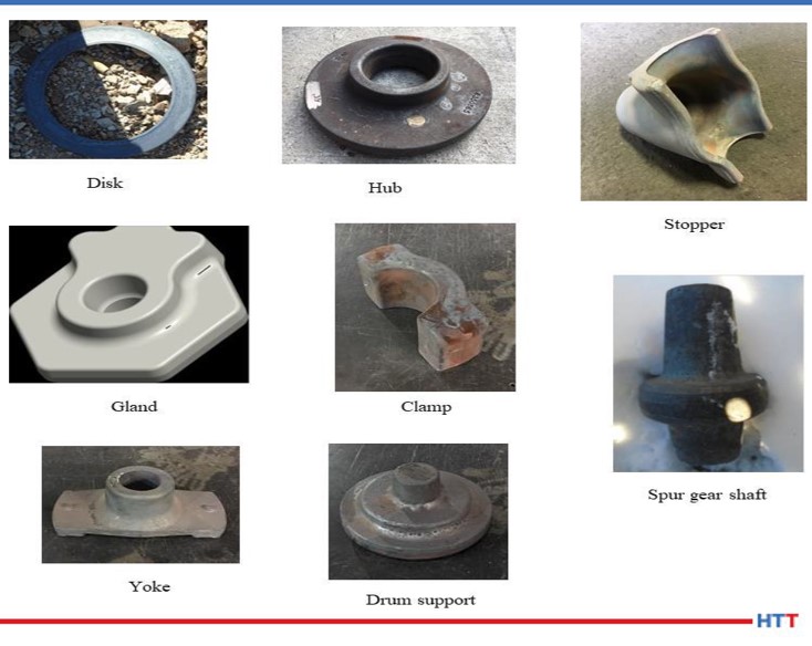
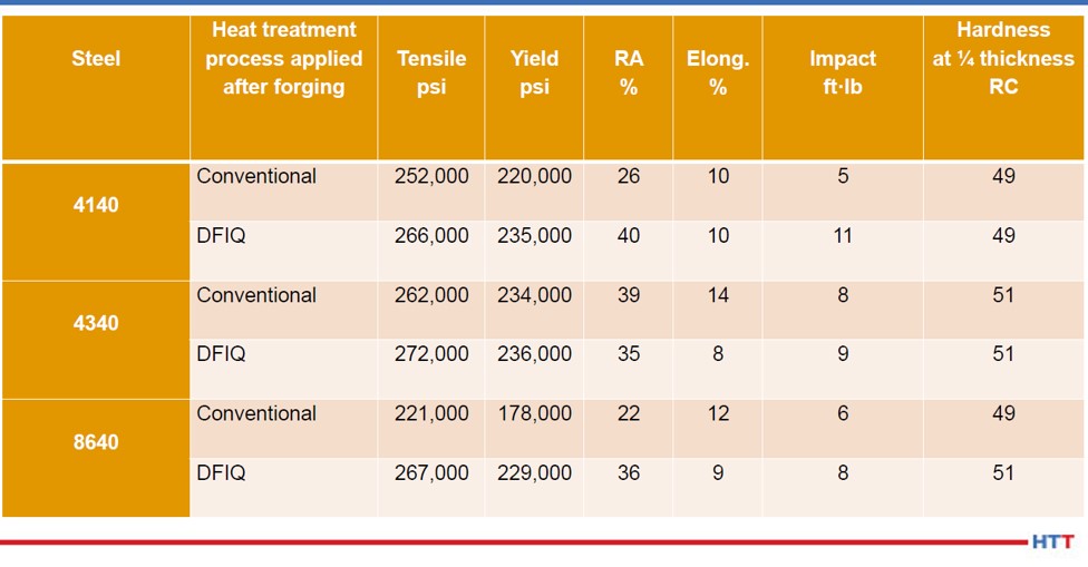
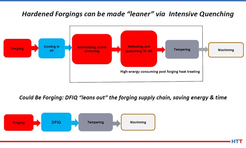


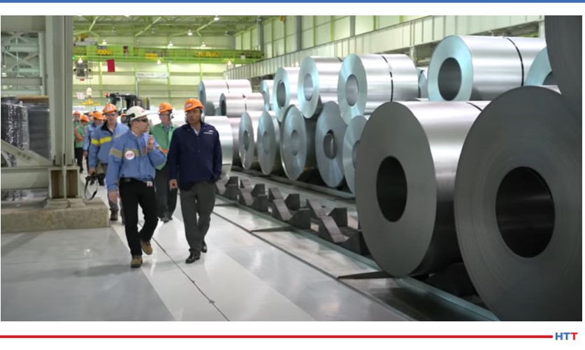
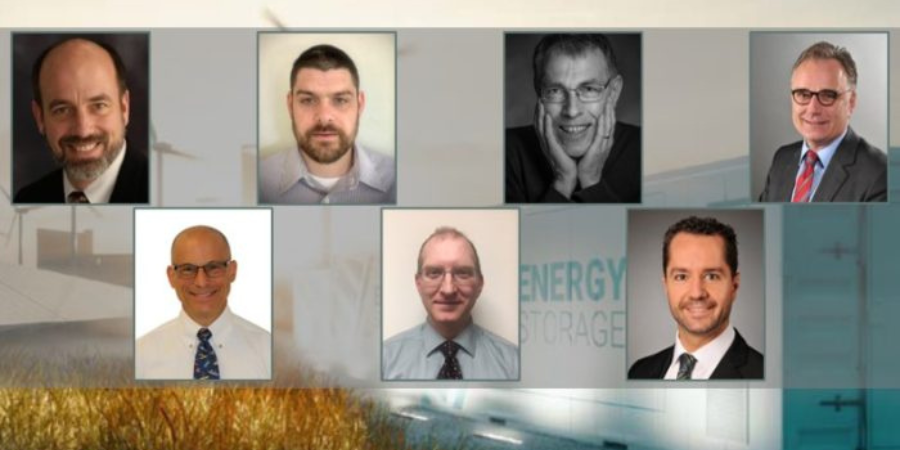


 Keenan Cokain, global sales and applications coordinator and Michael Cochran, an applications engineer, both from Pittsburgh’s Bloom Engineering, an industrial combustion and controls company, add another consideration: “Natural gas is a vital primary energy source globally and will likely remain so over the next 10 years. Although energy demands will likely show an overall decline in 2020, over the next 10 years, global natural gas consumption will likely rise as it continues to grow in comparison to other fossil fuels (such as oil and coal) as a percentage of the global primary energy consumed.