
Heat Treat Radio #83: Lunch & Learn with Heat Treat Today — Austempering
 Today's episode delves into the term "austempering". What is it? Why do heat treaters need to use it? For what applications is it necessary? Join Doug Glenn, publisher of Heat Treat Today and host of this podcast, as he talks with "The Heat Treat Doctor", Dan Herring, about all things austempering.
Below, you can watch the video, listen to the podcast by clicking on the audio play button, or read an edited transcript.
![]()
![]()
![]()
![]()
![]()
![]()
The following transcript has been edited for your reading enjoyment.

Doug Glenn (DG): Alright, welcome everyone. We’re here with another Lunch & Learn with Dan Herring. Today, we’re going to be talking about the principles of austempering. We do these Lunch & Learns really for the benefit of our Heat Treat Today team and we knew that learning from Dan would also be educational for the entire industry. We are just really happy to be able to have Dan Herring with us once again to educate us a bit. We’re going to try to spend about 30 minutes or so learning about some of the very basic principles of austempering. So, the ball is over the fence to you, Dan.
Dan Herring (DH): Well, welcome everyone. It’s my pleasure to discuss the heat treat topic that we call austempering. One of the things we’re going to do today is we’re going to recall from a previous Lunch & Learn the definition of heat treating. We called it the controlled application of time, temperature, and atmosphere to produce a predictable change in the internal structure of what metallurgists call the microstructure of a material. So, we’re going to introduce various words that are related to different types of microstructures today or these internal structures.
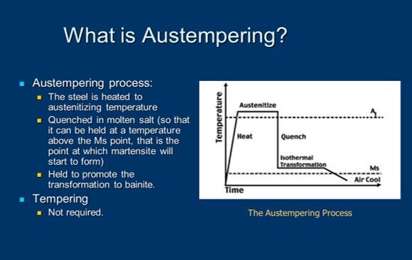 But before we do, I’ve put on the screen a brief definition of austempering. It’s certainly a heat treat process. It’s used in medium to high carbon, both plain and alloy steels, as well as cast irons (an example being ductile iron) and we’re trying to produce a microstructure called bainite which is probably a foreign word to most of you and I’ll endeavor to explain it in a moment.
But to give you just a view from about 30,000-feet, you might be asking yourself, “Well, what types of products are austempered and why?” So, I put a couple of examples here. I’ve put an example of a lawnmower blade, seat belt components like the tongue and receptacle, and some tractor parts, as well.
A good example of this might be the seatbelt components. We’ve learned to put on seatbelts (in my day, we didn’t have them, but now we do) and we all learned to buckle up. And, if you get into an accident, you discover why your seatbelt is really your friend. We want something that’s strong, that if we get into an accident, it will not shatter and break. But, at the same time, we want something that’s tough and slightly ductile so it will bend and not break.
Austempering is a process that’s used to produce all seatbelt components, that I’m aware of. Similarly, with lawnmower blades- we don’t want a blade, if it hits a rock as we’re mowing the lawn, (I don’t expect most of the people on the call to have mowed the lawn), but if we hit a rock or a hard object as we’re mowing the lawn, we might want that lawnmower blade to get a ding in it, but we don’t want it to shatter. So, those are some typical examples.
You might ask yourself, why do you austemper? What we’re seeing here is that if you need increased ductility, toughness, and strength at a given hardness level, austempering is right for you. We’re typically talking about parts that are in the range of, maybe, 35-55 Rockwell C. We are developing, as I said, a bainitic structure as opposed to a martensitic structure, which is what’s produced when we harden a steel and quench into something like oil or water.
So, we get improved toughness. And we get some superior properties related to that, as well. And some of the properties don’t change very much but they’re equal to what we get when we harden the steel, when we get this martensitic structure.
The bottom line is we typically get less distortion, we get better wear resistance, we don’t suffer from cracking as some of the high carbon steels are prone to do, and, interestingly enough, with cast irons, we get some, what are called "improved dampening characteristics" -- noise and vibration. So, wire is an important like, for example, in an automotive engine to have dampening characteristics because we want the engine to run quietly.
What types of materials can be austempered? This is just a partial list, but mostly it’s medium carbon steels. That’s carbon steels with anywhere from .5 carbon to .95 carbon or, in other words, an AISI 1050 to 1095 grade. We can also do medium alloy steels -- the 4130’s, the 4140’s, the 5140’s, the 5160’s, etc. Certain stainless steels can be austempered although not many of them. And, as I said, cast irons, the example being ductile iron, can also be austempered.
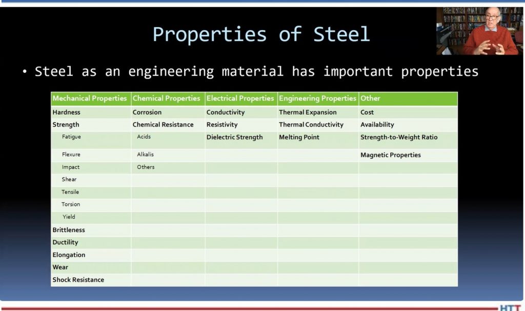
And I wanted to give you some idea of the mechanical and different properties of steel. We talked in an earlier Lunch & Learn about the fact that steel is an alloy of iron and carbon and manganese. And we add other elements to the mix in order to get various either mechanical properties, chemical properties, electrical or magnetic properties, and certain other advantages.
So, an example of mechanical properties that we’re typically interested in is hardness and strength, brittleness, ductility, elongation, wear, and shock resistance. Now, strength is measured a number of ways. There are things called "fatigue strength" and "flexure" and "impact strength" and "sheer strength" and "tensile strength" and "torsion strength" and "yield strength."
This is a metallurgist’s rendition of a teeter totter in a schoolyard. Now, don’t laugh. This is what defines the difference between a metallurgist and a mechanical engineer. For all the mechanical engineers out there, metallurgists draw cartoons -- that’s the easiest way to say it. Howsoever, at one point in all of our lives, we’ve probably been on a teeter totter. We know that, in this particular teeter totter, we have strength properties on one side of the teeter totter and ductility properties on the other. We know that as the strength goes up, the ductility will go down and as the ductility will go up, the strength will go down. As a result of this, we decide what we want for properties and we realize that there’s a compromise going on. If we make them extremely strong, they’ll be brittle because they’ll have very, very low ductility. If we make them extremely ductile, they’ll have very low strength. So, this balancing act is what we’re trying to do when we look at the properties we’re trying to achieve. And, if you remember, the microstructure is what gives us these properties.
Now, this is something that is not intended to confuse, but I thought I’d add a little metallurgy into the mix because we are going to talk about several microstructures. This is what metallurgists call a "time temperature transformation" or "TTT diagram." This is really an artist’s rendition of one. There is a lot more information typically contained in one of these diagrams. But for our purposes, it isn’t too important. We can use this artist’s rendition to get the essence of what we’re trying to do.
We start off by heating steel to austenitizing temperature. And that’s above the dotted line shown in this particular diagram, so, at the very top of those turquoise lines and temperature. And then what we do is we make sure that the component part is uniformly up to temperature and now we get ready to harden it. We get ready to quench it. What we’re dealing with is we’re rapidly cooling, and under normal hardening, you’ll notice that there are two lines there- one called MS and one called MF. MS is the martensite start line and MF is the martensite finish line.
Typically, in hardening, our goal is to produce martensite. In order to do so, we want to cool rapidly enough to miss what we call "the nose of the curve" because if you look at this type of diagram, you’ll see that it, on profile, looks like somebody’s nose and the turquoise lines are missing the "nose" of the curve. As a result of that, we’re cooling rapidly. But the difference between hardening and austempering is that we don’t cross the MS point, we don’t cross into the martensite range. We don’t transform to martensite, instead what we do is we put the brakes on, we stop, and then we introduce a long soak or hold period and we cross into the banitic range of the curve.
And, so, austempering is typically performed about 25-50 degrees Fahrenheit above the martensite start temperature of steel. Now, there are some exceptions, but that’s a very typical range. If we’re not controlling the process properly, we might get a microstructure that’s both bainite and martensite. But if we do our job right, we’ll get a fully bainitic structure, which is often what we desire.
Now (and I realize this has words that some people may be unfamiliar with) but we’ve heated the part up until we’re austenitic- we’re in the austenite range, and there are three various methods of cooling that can be employed. On the far righthand side, if we rapidly quench a part into oil or into water, we might produce a microstructure that’s called martensite. It’s a body-centered tetragonal microstructure. We get something that’s very hard, but brittle. That’s why we have to reheat it and perform a process called ‘tempering’ in order to take some of the brittleness away and add some ductility back in.
Now, on the far lefthand side, we may slow cool the part rather than rapidly quench it and we produce a microstructure that is both ferrite and pearlite, the result of slow cooling. So, instead of getting something that’s very hard, we get something that is very soft. You might say, “My gosh, why do we want to do that?” Well, we like to do that sometimes because we like to take a steel and, for example, machine it into a final form before we go back in and reharden it. So, as a result of that, we form a ferrite/pearlite microstructure, we’re able to machine the part, then we can go back in and reharden it.
So, slow cooling gives us a ferrite/pearlite microstructure, rapid quenching gives us a martensitic microstructure, and a moderate cooling rate (the one shown in the center) gives us a bainitic microstructure. Bainite is a mixture of ferrite and cementite. Again, words that you’re perhaps not familiar with. But the way I like to say it is martensite gives us a microstructure that is not as hard as martensite but tougher, in general, than martensite, and we’ll explain that as we move forward.
But I thought before we do, you might want to see some typical type of heat-treating equipment that is used to austemper parts. A lot of parts are done in a mesh belt conveyer line. The one that is shown on the left, where parts are loaded onto a table, sent through the furnace, and dropped at the end of the furnace into a salt quench which is located in the floor, in this particular drawing. Salt is the primary medium that we quench parts that will be austempered in because salt gives us the temperature-range we need to be above the martensite start point.
Now, a number of people have asked me in the past: Can I use oil rather than molten salt to perform this operation? There are certain oils that can be used at extremely high temperature, but there are fire hazards and other hazards associated with them so the typical answer is ‘no’; molten salt is typically used to perform the quenching.
So, you have a mesh belt conveyer system for high volume, shown on the left. On the right, you’re showing a typical Shaker Hearth furnace where what happens is you load parts onto a pan that vibrates and the parts are moved down the length of the furnace and then drop into a salt quench at the back end.
I thought you might want to see some pictures of some stampings and things that are going into one of these mesh belt conveyer furnaces. You see the endothermic gas in this particular picture burning out the front of the furnace and the stampings moving on a conveyor belt, a mesh belt, in through the furnace. All sorts of different types, shapes, and sizes of stampings. One thing you’ll notice is that these parts are, typically, not single layer loaded; they’re loaded, perhaps, one to three to five parts thick, somewhere between anywhere from a half inch to about two or three inches thick as they’re moving through this conveyor belt.
And to complete the metallurgy aspect of it, you might say, “Hey, what type of microstructure am I actually seeing?” The picture on the left is a primarily bainitic microstructure with some martensite and its hardness is 44 Rockwell C. The microstructure on the righthand side is a combination of bainite and ferrite. The ferrite in this microstructure shows up as white or very light in color, exactly. This hardness, because you have ferrite present, is about 36 HRC. So, depending on the hardness you’re trying to achieve, you will get different types of microstructures- that’s the purpose of this slide.
Now, as far as molten salt goes, a typical austempering bath consists of either a sodium nitrate or a potassium nitrate salt, typically in a 50/50 mixture, and this salt is operating somewhere between 300 degrees Fahrenheit and 650 degrees Fahrenheit, depending on, again, the desired, not only the composition in the salt, but the desired temperature that we would want to hold to.
Let me back up for a second, Doug. So, to kind of summarize this: What we’re trying to put the brakes on as we’re rapidly cooling down, missing the nose of the transformation curve, we want to fall into this bainitic region and, in order to do so, we need to stay above that martensite start temperature which for many steels is in the 400–450-degree Fahrenheit range. So, our molten salts will typically run at 475, 500, even 550 degrees, all the way up to 650 degrees. So, we pick our salt temperature, not only depending on the salt, but also depending on the temperature that we want to hold the bath in.
Some of the reasons for selecting a salt quench are that the temperature of the salt bath dictates the ultimate hardness that we’re going to achieve. You might find this interesting: If I didn’t mention it in a previous Lunch & Learn, but I did, it’s that when we quench into the martensite range or field, martensite is the instantaneous sheer transformation. It really progresses at the speed of sound. So, martensite forms almost instantaneously, but bainite requires time for the transformation to take place.
So, a typical time in the salt is somewhere in the range of 18-20 minutes. I’ve seen parts held in salt for as short as 10 or 12 minutes and for as long as 30 minutes, but it depends on the thickness of the part, the material and, ultimately, the desired hardness we are going to reach. Now, interestingly enough, as opposed to a part that we harden to martensite and have to retemper or temper to balance the teeter totter, so to speak, with an austempering process, we do not need to temper afterwork because the parts are effectively tempered, so to speak, in the salt. So, we have a hardening operation that results in a banitic structure but we don’t need to temper. So, that’s one of the differences between hardening and austempering.
Again, the time in the salt will decrease as the transformation temperature increases and the time in the salt is similarly associated with the carbon content in the steel.
Let me give you a couple of examples: I mentioned in an earlier slide that SAE 1050, 1055, 1075 steel are typical steels that are austempered. Again, your austempering goes to put the hardness typically in the range of 40-45 Rockwell C, not nearly as hard as if we harden and quench them into oil or water, but certainly hard enough to give you a properly austempered part, giving you this part that is a combination of good hardness and yet a lot of ductility.
This, in a nutshell, is a brief summary of austempering. We’ve kind of said what it is -- it’s a process that’s going to get us a bainitic microstructure. We’ve looked at a little of the metallurgy of what we’re dealing with here and we’ve seen that it’s a different type of microstructure than is something like annealing or normalizing which gives you a primarily ferritic and pearlitic microstructure. And it’s different than hardening that gives you primarily a martensitic or tempered martensitic structure.
So, for those parts that require not only hardness but toughness, austempering is a process that should be considered by heat treaters.
Doug, that’s really the end of the presentation that I’ve prepared. We can certainly discuss it a little bit more if anyone has any questions.
DG: At the beginning, you were talking about pearlite and all that stuff, did we talk about austenite?
DH: Well, we talked about austenite because, again, that’s the temperature to which we heat the parts up to at the very beginning. In other words, to start the process, we heat the parts up to the austenite field, if you will. In other words, the parts are essentially red hot. They are above the proper transformation point that they turn into austenite.
DG: So, I assume that’s here, if you guys can still see the images: That’s austenite. The austenitic temperature is up above this dash line, right?
DH: That’s correct.
DG: And as you bring it down, you come through, perhaps, other, there’s a lot of different "ites" in heat treating, right? There’s austenite, pearlite, ferrite, bainite, martensite, you know, it sounds like a stalagmite and whatever those other things are in the caves, but all of those things basically are telling us about the orientation of the molecules inside the metal.
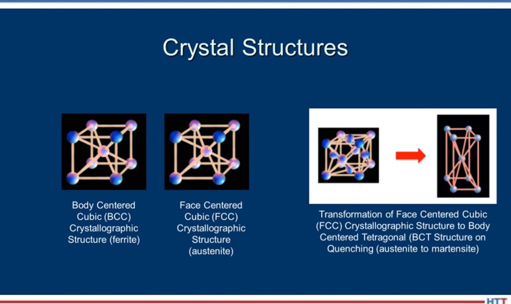 DH: Well, think of it this way, Doug: When we have a steel, its microstructure, if it isn’t hardened, its microstructure is typically body-centered cubic, which means the atoms are all lined up in a certain structure. Now, what we do when we heat it up is -- when it gets above the transformation temperature (that dotted line, for simplicity, in this example) the atoms will realign themselves from body-centered cubic to face-centered cubic and a face-centered cubic structure is called austenite. Then, when we quench it, until we move into the nose of the curve or past those red lines, we still maintain an austenitic crystal structure as we’re cooling. The ferrite, the pearlite and things occur when we cross over into those reddish lines in that area there.
I think you can do this- if we start off as austenite, and we slow, slow cool.
Slow, slow cool. We go all the way down like that. Keep going down, down, down, down, down. Okay, if we do something like that, (and I’ve got some pictures to show it better), but the idea being the fact that because we’ve fallen into the nose of the curve, we form a microstructure that is typically ferrite and pearlite. The first line you’ve drawn is indicative of an annealing process where we’re slow cooling inside the furnace. The second line you’ve drawn is more indicative of a normalizing process where we’ve cooled at a faster rate but still, in this case, we’ve fallen into the nose of the curve because it’s not that quick.
And to give everyone a perspective of the time element involved here, and I haven’t shown numbers, but the time element is for plain carbon steels, you may only have a few seconds to reach the nose of the curve. So, as a result of that, you have to move very rapidly where those turquoise lines are shown; you’re cooling at a very, very, very rapid rate to try to miss the nose of that transformation curve.
The secret with austempering is that you have to put the brakes on before you form martensite, and that’s not as easy as you might think it is. But that’s one of the reasons why molten salt is an excellent medium to quench into.
Don’t mix up crystal structures with microstructures. The ferrite, the pearlite, the bainite, the martensite are microstructures whereas the crystallographic structures -- body-centered cubic, face-centered cubic, body-centered tetragonal- represent how the atoms realign themselves.
DG: Does anybody have questions for Dan?
Bethany Leone (BL): I was thinking about asking you, Dan, but you have already essentially answered it: How difficult is it to have that rapid cooling and then control it to remain quite stable for a long period of time? You hit on the first part of the question which is the salt quench does a good job in this instance. But how does a heat treater maintain that stability of temperature for such a long time?
DH: That’s a great question because one of the interesting properties of salt, molten salt, is the fact that it is a bath that’s extremely uniform in temperature. So, when, for example, the parts, the stampings, and other parts are conveyed through a furnace, they then drop off into a quench and there is a conveyer belt in the quench, under the salt, that the parts drop on to this conveyor belt and then move through the salt. So, if I want 20 minutes in the salt bath, I have to run the speed of the conveyor slow enough to allow that time to take place.
Now, not to confuse everyone, but there are other ways you can austemper: You can heat in molten salt and then quench in the molten salt. So, there is a molten salt you can actually preheat in molten salt, have a high heat in molten salt and then a quench in molten salt. A lot of people don’t use that for high volume production work, but they still use that.
But, yes, you need time in the salt for that transformation to fully take place.
DG: Any other questions?
Let me do a couple other things and, again, we can probably put this up on the screen, but we just recently, I believe, already released this -- the Heat Treat Radio interview we did with Bill Disler regarding salt quenching. That may be of interest to people who have an interest in what about salt quenching? You might want to reference that sometime so, feel free to look into that. You also can just search our website for "bainite" or "austempering" and you may come up with some additional articles.
So, that’s it. Dan, thank you very much. I appreciate it. Unless anybody else another question, I think we’ll sign off at this point.
DH: Good! We will see you next time.
DG: Alright, sounds good. Thank you, guys.
BL: Thanks, Dan.
DH: Thank you.

Doug Glenn
Publisher
Heat Treat Today
To find other Heat Treat Radio episodes, go to www.heattreattoday.com/radio .
Search heat treat equipment and service providers on Heat Treat Buyers Guide.com
Heat Treat Radio #83: Lunch & Learn with Heat Treat Today — Austempering Read More »
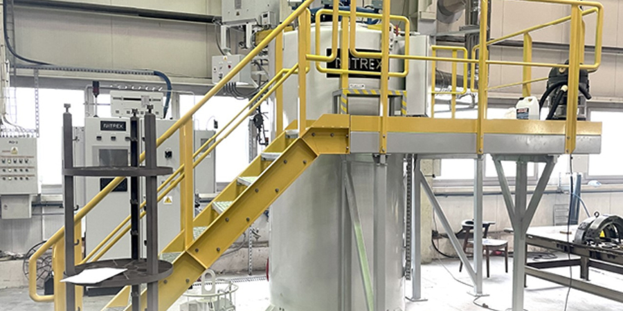
 A manufacturer in Poland turns to in-house heat treating capabilities rather than outsourcing its nitriding for stainless steel power generation parts. Steam turbine components will now be processed at the facility in Elbląg as a result of funding help from a government program part of the European Union.
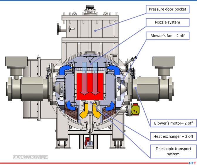
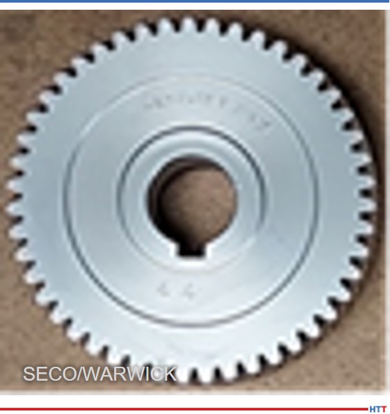
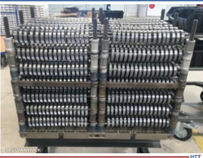
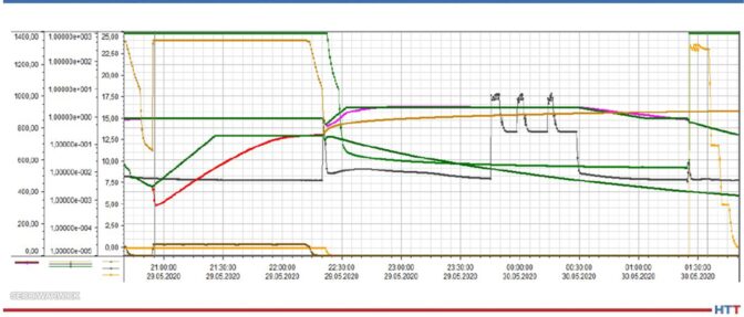
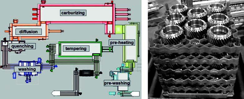 This paper reveals the investigation and conclusions of distortion potentials for case hardening processes. Mainly, the focus was on how the SyncroTherm® concept method compared to conventional case-hardening processes for gears and sliding sleeves.
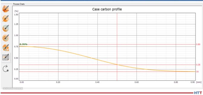
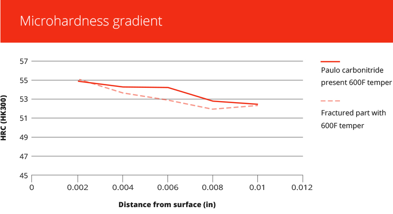 Problems in heat treating result in the loss of valuable time and money. Getting to the bottom of those problems also usually takes time and money to investigate what's happening and how to fix it. What is a heat treater to do?
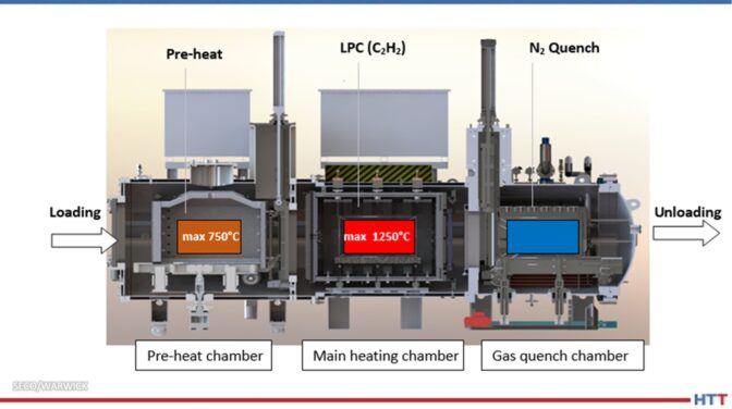
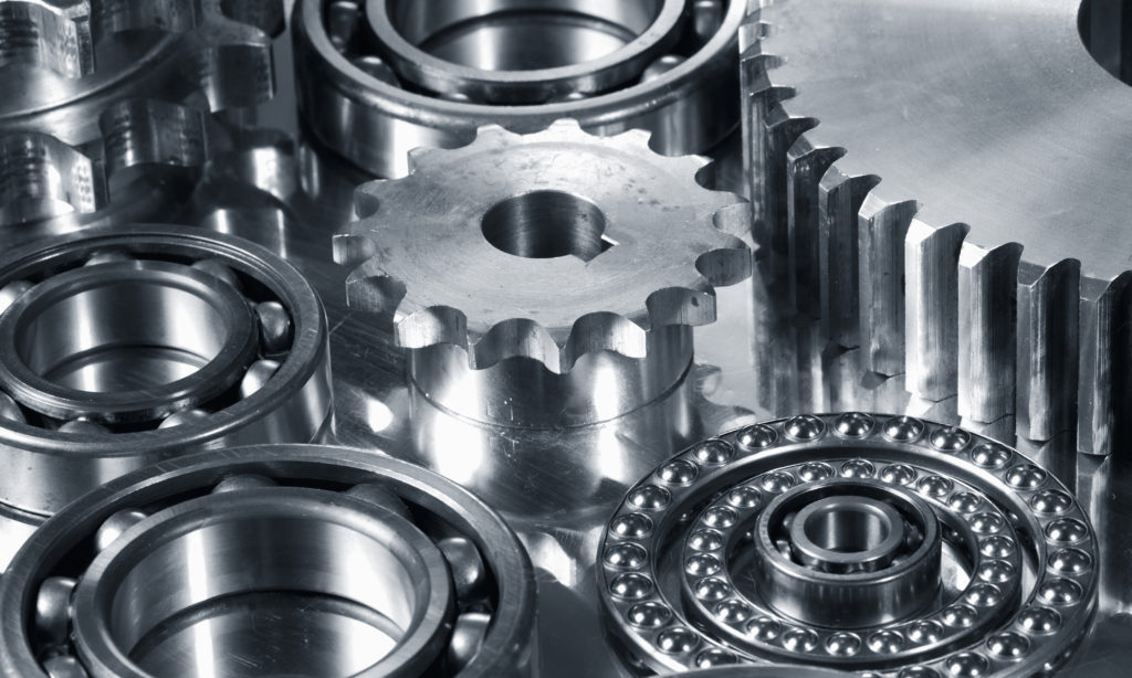 Low pressure carburizing (LPC) furnaces play an important role in the automotive heat treating industry. During LPC, it is essential that processing temperature stays consistent and critical that the processing time frame is monitored.
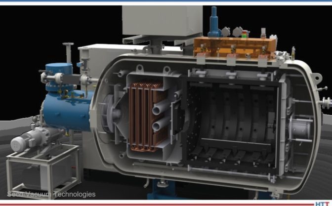
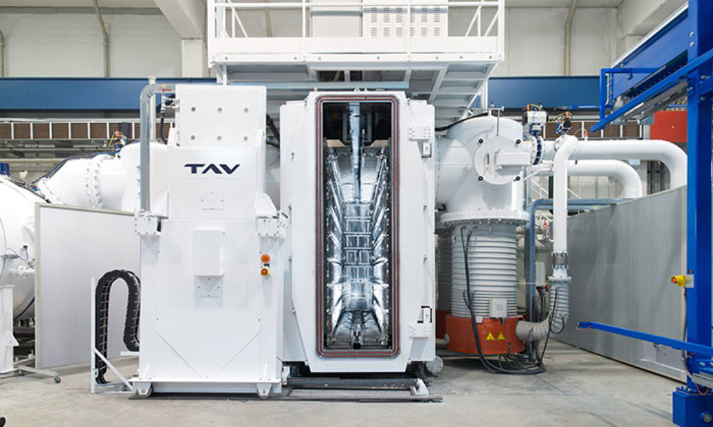 Time to brush up on a vacuum brazing furnace, but automotive industry style. Review the terms, parts, function, and more that are involved in a successful vacuum braze for automotive parts.
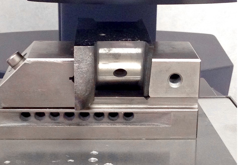 If you've ever heat treated automotive crank pins, you're probably familiar with at least one type of hardness test that case hardened crank pins are tested against. The big question is, which hardness testing method is better: automated or manual? This article compares these two methods to make and measure Vickers indentations.
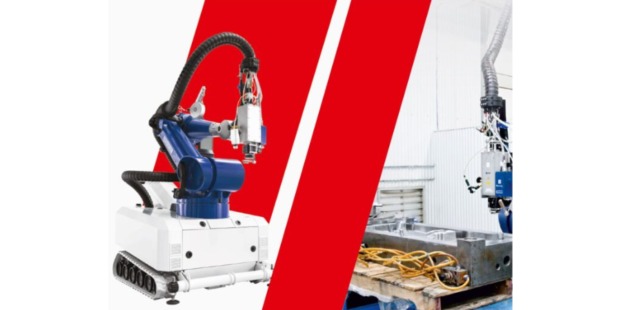


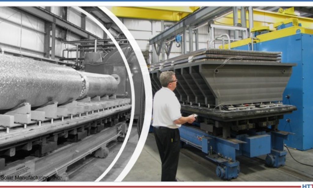
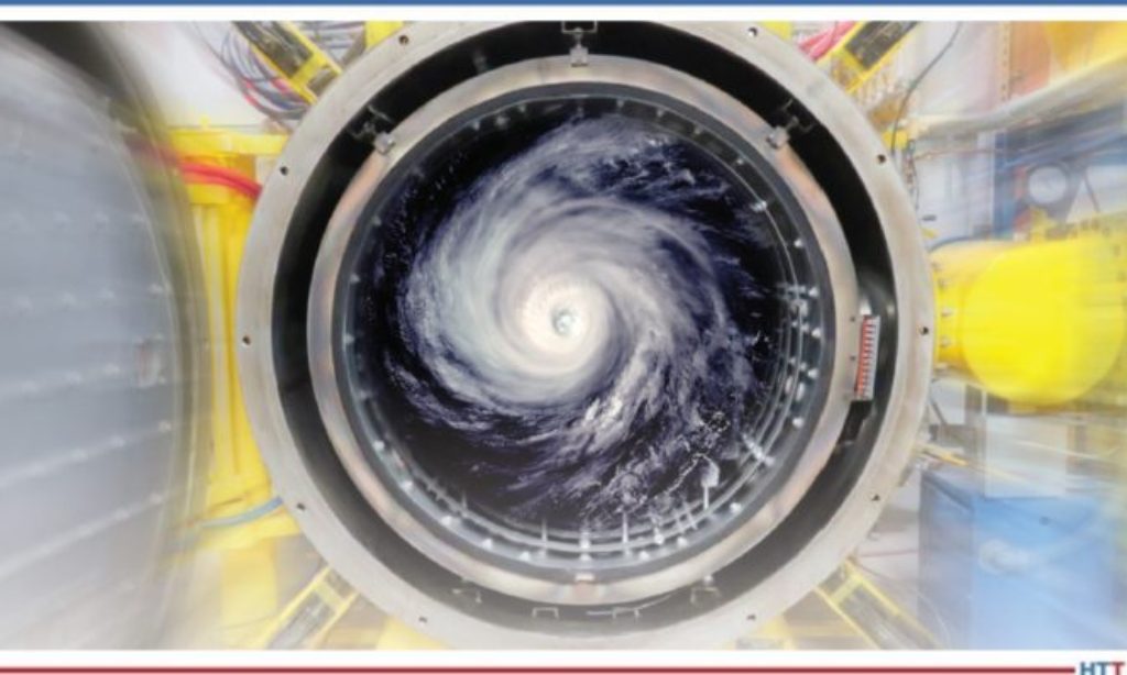
 If you like to read about how heat treaters can be game changers in multinational science projects, this is the article for you. A specially designed vacuum heat treat furnace was commissioned to heat treat critical components in a large energy generator. The heat treating of these components takes 5 weeks to complete; talk about a long, uniform heat treat period.