Schüler, J. Kleff, V. Heuer, G. Schmitt, T. Leist
A systematical approach regarding different distortion potentials in the process chain describes the influence on dimensional and shape changes of gears and sliding sleeves after case-hardening, like part geometry, cold and hot forming of blanks, carburizing concept and temperature profile, oil and gas quenching, as well as individual press and batch hardening. The results show an excellent potential of the new SyncroTherm® concept compared to the conventional case-hardening process for gears and sliding sleeves. Stable distortion characteristics even at elevated temperatures and without decreasing to hardening temperature as well as a good performance after two-dimensional batch quenching instead of the much more expensive individual press quenching were found in this study. Very sensitive part geometries are still a challenge. A clear limitation was found when processing cold formed blanks without annealing before soft machining.
Authors: Andreas Schüler, Dr.-Ing. Jörg Kleff, ZF Friedrichshafen AG, Alfred-Colsman-Platz 1, 88046 Friedrichshafen, Andreas.Schueler@zf.com (Corresponding author)
Dr. Volker Heuer, Gunther Schmitt, Dr. Thorsten Leist, ALD Vacuum Technologies GmbH, Hanau
1. Introduction
Case hardening is the most common heat treatment for gears, shafts and synchronizer parts used in gear boxes for automotive and commercial vehicle applications. A combination of high fatigue resistance as well as good machinability and reliable process stability in heat treatment ensures transmission components with maximum strength, excellent performance and cost efficient production. In order to decrease the costs for hard machining and reduce the risk of grinding burns the knowledge of distortion characteristics for the individual part as well as distortion carrier potentials of the entire process chain is essential for an improved series production with minimum stock removal [1]. Even today with much higher requirements relating to lightweight design of automotive part geometries this aspect becomes more and more important [2]. Predictable and stable distortion characteristics are still a challenge especially for sensitive parts with thin cross-sections, non-symmetric design and a global production with many different suppliers in the process chain. In a constant pursuit for optimizing, ZF in Friedrichshafen investigated the potential of new heat treatment concepts with the advantages of reduced costs, quicker processes and less distortion. A comparison of the new heat treatment concept SyncroTherm® from ALD Vacuum Technologies was performed with the conventional benchmark concepts of a) case-hardening of gears in a pusher-type furnace with atmospheric gas carburizing and oil quenching and b) press quenching of sliding sleeves directly after gas carburizing in a rotary furnace. The “SyncroTherm®” heat treatment concept combines the benefits of smaller furnaces and two-dimensional batches, fast low-pressure carburizing (LPC) at elevated temperatures and reduced distortion by applying high-pressure gas quenching and the possibility of part-related individual quenching parameters [3].
2. Standard processes for transmission components at ZF Friedrichshafen
2.1 Material, forging and machining
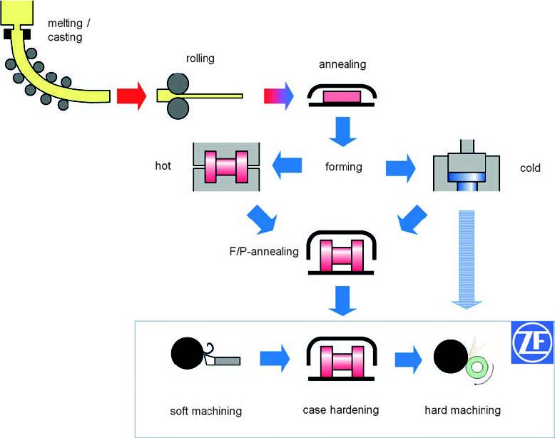
The material for transmission components like gears and synchronizer parts is the case-hardening steel ZF7B which is a modified 20MnCr5. The process chain is shown in Figure 1. The material for automotive and commercial vehicle applications is usually continuously casted and formed to different bar geometries in the steel mill. The forging supplier performs either hot or cold forming of blanks. The gears investigated in this study were all hot formed and later F/P-annealed with an isothermal transformation in order to ensure a good machinability of the ferritic/ pearlitic microstructure. The forged blanks are soft machined by turning and teeth milling. Measurements of characteristic dimensions, shapes and teeth geometries were performed before and after heat treatment in order to describe the distortion behavior. Grinding the bore and teeth flanks is usually performed as the last process before assembling into the gear box. Two different process chains were investigated for the siding sleeve. The first one was similar to the gears with hot forming, F/P-annealing and soft machining. The other process chain for similar part geometry of the sliding sleeve was cold rolling and broaching of the internal spline without F/P-annealing. Different dimensions and shapes which are sensitive to distortion were measured before and after case hardening.
2.2 Case-hardening in pusher-type furnaces
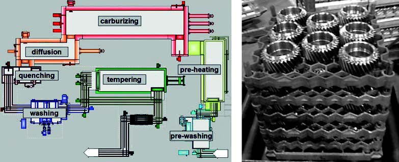
The typical final heat treatment of gears is case-hardening in a pusher-type furnace. The gears are charged in three-dimensional batches of around 220 kg per batch including fixtures. The batches of helical and planet gears which were investigated in this study were loaded by different layers of gears on grids (Figure 2). Depending on the case-hardening depth with an individual cycle time the batch is pushed through the furnace with the different linked processes pre-washing, pre-heating at 480 °C, carburizing at 940 °C, decreasing to hardening temperature 850 °C, oil quenching, washing, tempering at 170 °C and cooling down to approximately 50 °C.
2.2 Case-hardening in rotary furnaces and press quenching
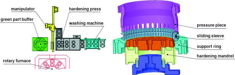
More distortion critical synchronizer parts, like the sliding sleeve, are carburized in a rotary furnace at 930 °C with different levels in the furnace.For a three-track press quench three parts are laying on a tablet and the tablet moves in a cycle time of approximately 70 s through the rotary furnace in order to achieve the required case-hardening depth of around 0.5 mm. The parts are quenched directly from carburizing temperature 930 °C and different tools are fixed to the part before quenching which is shown in Figure 3. During the quenching process the inner diameter of the sliding sleeve shrinks onto the mandrel with similar tooth geometry as the internal spline of the part. This behavior enables a constant inner diameter and position of teeth with less run-out and scattering. In order to adjust the flatness the sliding sleeve is pushed by a pressure piece onto the support ring during quenching. All tools are designed with oil drillings in order to achieve an efficient and uniform quenching of the cross-section. The distortion characteristics of press quenched parts are extremely depending on the design of individual tools and the quenching parameters like temperature and flow of the quenching oil or retention force of the pressure piece. Most synchronizer parts are ready for assembling after press hardening and shot blasting, no additional hard machining is performed anymore.
3. Investigation
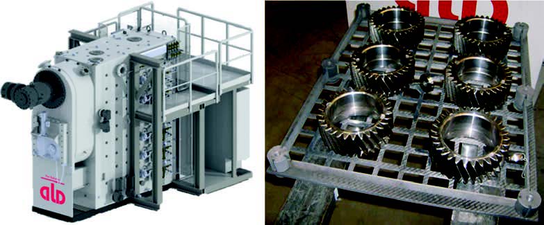
The main idea of ALD-SyncroTherm® concept is a small and flexible furnace that can realize a quick low-pressure carburizing process (LPC) at elevated temperatures and reduced distortion behavior of the carburized parts by using an adjustable high-pressure gas quenching. Differently from the standard processes at ZF, parts are loaded in one single 2D-layer on light carbon-fibre tablets, as shown in Figure 4, and then directly heated up to carburizing temperature real quick, which can be up to 1050 °C. The LPC furnace with its small floor space of e. g. a turning machine has up to six single carburizing slots, where each tablet can be heat treated individually. After the carburizing process has been finished, the parts are transported to the internal gas quenching chamber where the parts are quenched directly from carburizing temperature (see Figure 4 left) [4].
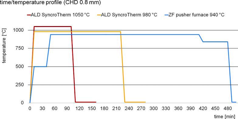
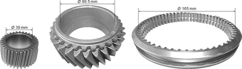
This is also a deviation to the direct batch quenching process at ZF where the part temperature is lowered to hardening temperature 840 °C before quenching with respect to distortion. Figure 5 shows a comparison of three different time/ temperature profiles which were tested within this analysis in order to achieve a CHD of 0.8 mm. The standard batch hardening process in a pusher-type furnace is compared to two different LPC processes with variation in carburizing temperature. In order to reduce distortion already during heating, the parts in the standard process at ZF are not being heated up to carburizing temperature directly but have a pre-heating step at 490 °C in order to equalize the core and surface temperature. For the LPC process with carburizing at 980 °C the overall process time is much shorter due to the higher temperature and the missing pre-heating step and the direct quenching from carburizing temperature. The reduced process time is even more pronounced when carburizing is performed at 1050 °C. All three profiles have been tested with different common parts for truck and bus transmissions. Figure 6 shows the three types of parts that have been chosen. The tests have been performed with a small planetary gear for bus transmissions and a heavier and bigger helical gear for heavy truck transmissions. Both gears are direct hardened at ZF by using the batch hardening process in a pusher-type furnace. Other experiments have been performed with two different types of sliding sleeves but similar geometry, as shown in Figure 6. Both types of sliding sleeves were processed differently: one type is machined from cold formed blanks whereas the other type is machined from hot formed and F/P-annealed blanks. Due to their high distortion potential, the standard process for sliding sleeves at ZF is carburizing in rotary furnaces with a consecutive press quenching. For each part many different dimensions, shapes and tooth geometries were measured before and after heat treatment in order to describe the individual distortion characteristics. Here, just critical features are shown which are representative for the distortion characteristics. For gears those are the internal diameter of the bore and the angular flank deviation fHb of the teeth. For the sliding sleeves the diameter of the internal spline and the flatness of the end face are the critical characteristics.
4. Results
4.1 Metallographic results
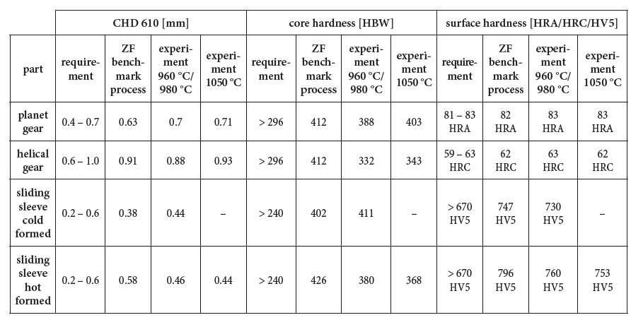
Metallographic results of the different tests were analyzed by investigation of one part from each batch since a correct metallographic result is the premise for the later analysis of the distortion and evaluation of the LPC process. Table 1 shows the different metallographic results of the analyzed parts from experiments at different carburizing temperatures and the results of the ZF benchmark processes, as a comparison. It shows that the LPC furnace is able to produce correct and repeatable metallographic results within specification regarding CHD, surface hardness and core strength.
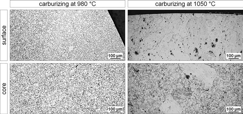
For bigger cross sections, like for the helical gear, the lower core strength is explainable due to the lower quenching speed of gas quenching compared to oil quenching in general and even further reduced gas quenching speed with respect to distortion of this gear. Additionally the amount of retained austenite could be maintained well within the required specification (max. 30 %) with the ALD furnace, even after quenching directly from carburizing temperature. Figure 7 shows micrographs of the grain sizes from core and surface samples taken from the heat treated parts with carburizing at 980 °C and 1050 °C and etched according to Bechet-Beaujard. Whereas the samples which were carburized at 980 °C show a homogeneous distribution of fine grains with grain size classes 5 and finer, the samples carburized at 1050 °C show an inhomogeneous distribution and very coarse grains with grain size classes up to 1 and coarser. These findings where confirmed through all performed experiments. This shows that conventional ZF case-hardening steel grades can already provide grain size stability up to 980 °C but not higher. For carburizing the parts at 1050 °C significant grain growth will occur in conventional grades. In order to prevent coarse grains microalloyed case-hardening steels are definitely necessary in order to meet the grain size specification [5]. Even knowing this fact already at the beginning, distortion experiments were performed at the higher temperatures, nevertheless, in order to analyze also the effect of grain growth on the part geometry and on distortion characteristics after heat treatment.
4.2 Comparison of distortion results – internal diameter of planet gears
In order to analyze the distortion of the internal bore, it was measured in three different levels of the bore. Figure 8 shows the location of the measuring levels M1-M3 within the internal bore of planet gears and the respective results from the green parts (12 sample parts), the benchmark process (24 sample parts) and the LPC experiment at 980 °C (12 sample parts).
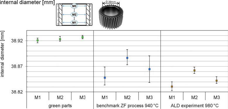
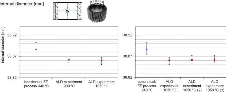
Whereas the three average values of the green parts show a perfect cylindrical form of the bore with almost no scattering, the measurement of the ZF benchmark process carburized at 940 °C shows a clear barrel shape of the internal bore with higher scattering. The same shape change can be observed in the results from the LPC experiment, although the value of the shape change and the scattering is less pronounced. The significantly lesser scattering of the heat treatment distortion compared to the benchmark process was even realized during experiments with a high carburizing temperature of 1050 °C (see Figure 9 left). Moreover the average value stays on the same level as after the experiment at 980 °C even if a significant grain growth was determined with no negative influence on distortion characteristics. The smaller diameter of the bore compared to the ZF process is explainable with the direct quenching from carburizing temperature without lowering the temperature, as it is done during the ZF process. These results are very stable even after carburizing at 1050 °C and were confirmed by two additional batches with same heat treatment parameters (Figure 9 right).
4.3 Comparison of distortion results – angular deviation of flank line fHβ
The value fHβ describes the angular deviation of a measured line along the tooth flank (see Figure 10) from the theoretically defined line of the tooth flank. It was measured on the left and on the right flank of three teeth per gear with a distance of 120° on the circumference. The same teeth and flanks have been measured before and after heat treatment. The results show that the fHβ of both flanks is highly influenced by the case hardening process. If compared to the measurements of the green parts, where the average value of the deviation is almost 0 mm with a maximum range of 0.02 mm, the average deviation after the benchmark heat treatment is −0.03 mm with a wide range for both flanks up to 0.08 mm.
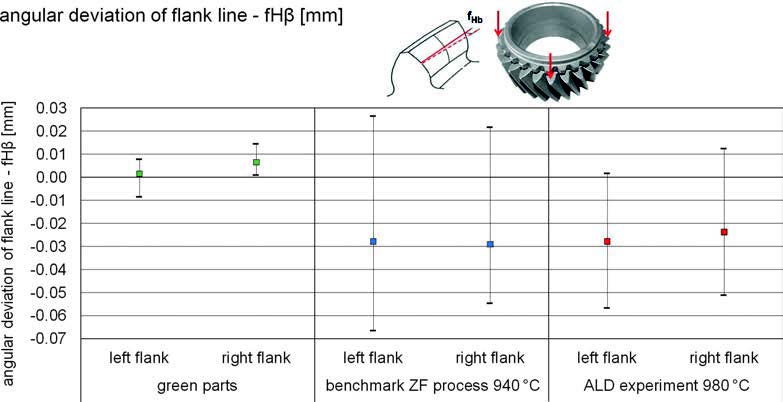
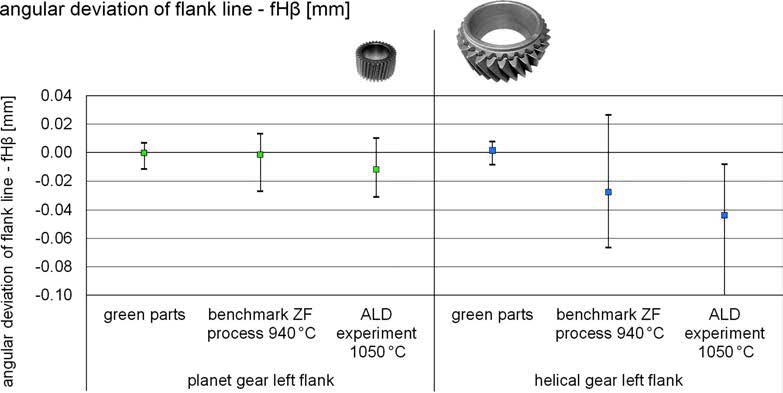
The results of the LPC experiments are comparable to the benchmark process and even slightly better. While average deviation of both tooth flanks is on the same level as the value after the ZF process, the range is slightly smaller. The maximum range for the LPC tests at 980 °C is 0.06 mm even if the parts were directly quenched from carburizing temperature. Figure 11 shows that the average angular deviation and the range are less influenced by the heat treatment concept and the carburizing temperature of the process. Especially for the LPC process, negative influences on distortion may be compensated by adapted and optimized gas quenching parameters. Comparing the much smaller planet gear (tooth width 34 mm, helical angle 7°) with the bigger helical gear (tooth width 50 mm, helical angle 23°) different characteristics regarding the average and range of angular deviation can be determined. The planet gear shows a similar average of fHβ before and after heat treatment for both heat treatment concepts and different carburizing temperatures. The range of fHβ is slightly increased after heat treatment and is similar for the benchmark and the LPC process. For the bigger helical gear it is different. The average of fHβ changes after heat treatment significantly and the range is much higher. There is also a significant difference between the benchmark and the LPC process for the average of fHβ but not for the range of fHβ. This is a clear indication for more sensitive distortion characteristics of the helical gear. The significant difference in distortion behavior is mainly influenced by the bigger helical angle of the wider helical gear compared to the narrower planet gear with the smaller helical angle [6].
4.4 Comparison of distortion results – sliding sleeves
Sliding sleeves are distortion critical parts and therefore are case hardened and press quenched as a standard process in the ZF Company. In order to define the distortion of sliding sleeves, the internal diameter and the flatness where investigated. Different from the batch quenching in the LPC furnace, both characteristics are being controlled during press quenching of the ZF benchmark process by using individual press hardening tools. The investigation has been performed with 10 pieces of green parts, 25 pieces for the benchmark process and 10 pieces for each of the LPC experiments. For a better comparability of the results, the values of the measurements have been standardized and fitted into the tolerance band so that a value of 0 mm indicates the exact center of the allowed tolerance.
4.4.1 Cold formed
The investigation of the sliding sleeves machined from cold formed blanks shows how the press hardening tools of the ZF benchmark process influences the internal diameter by forcing it to shrink onto a defined tool diameter of the hardening mandrel. The intended negative deviation of the green parts of 0.05 mm from the ideal diameter, based on long-term experiences, is corrected after the ZF heat treatment (Figure 12). Additionally the press hardening tools reduce the scattering of dimensional and shape changes to a minimum. The results after carburizing at 960 °C and gas quenching in a batch of the LPC furnace display a tremendous heat treatment distortion and scattering of results in a large range. Even with optimized quenching parameters the range is nearly 1.0 mm. The reason for this worse distortion behavior can be explained by the high amount of residual stresses after cold forming of the blanks which are not removed by later annealing and soft machining.
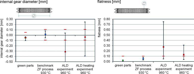
A heating experiment where the parts were heated up to 960 °C without carburizing and afterwards slowly cooled down to room temperature was performed. This test was done in order to define the amount of distortion that is induced by residual stresses from former process steps already during heating. It clearly shows a high distortion potential of the sliding sleeves machined from cold formed blanks. Whereas the average diameter does not change the scattering is very large and, with a range of 0.65 mm, almost as wide as after the complete process with carburizing and quenching (Figure 12 left). This assumption was also confirmed by the distortion analysis of the parts flatness (Figure 12 right) where similar distortion behavior can be observed. This means that, without controlling dimensions by hardening tools, sliding sleeves that are machined from cold formed blanks cannot be heat treated within the required specification.
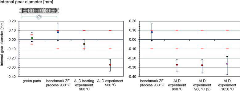
4.4.2 Hot formed
The distortion of sliding sleeves machined from hot formed blanks with a later F/P-annealing before soft machining, which reduces the residual stresses from prior process steps to a minimum, is significantly different compared to the cold formed sliding sleeve without F/P-annealing like previously described. The average diameter of the sliding sleeve after the ZF benchmark process is located near the upper tolerance with a slightly wider scattering (Figure 13 left) than after the heat treatment of cold formed sliding sleeves. Even by using optimized hardening tools for each part geometry the individual distortion behavior depends also on the forging lot and hardenability of the individual steel heat. Although some parts were outside of tolerance the final gage test applied on these parts showed that they are still usable for assembly. The heating experiment in the LPC furnace without carburizing reveals a smaller distortion potential due to minimized residual stresses of the hot formed and F/P-annealed blanks. Looking at the range of the diameter, it is just slightly wider when compared with the range of the green parts. This minimal distortion regarding the range can be preserved even after a completed experiment with carburizing and optimized gas quenching. Still, without the limiting function of a hardening mandrel, the average diameter shrinks as much as −0.38 mm after the heat treatment (Figure 13 left). The reproducibility of the described behavior of the LPC experiment with hot formed sliding sleeves was confirmed by two additional experiments with carburizing temperatures of 960 °C and of 1050 °C (Figure 13 right). Even the sliding sleeves from the final test that were carburized at 1050 °C show an average diameter that remains stable at the same level as those carburized at 960 °C. The additional scattering, that results of a higher quenching intensity, is minimal and in total still less than the tolerance band width of 0.2 mm. Therefore, producing sliding sleeves with the LPC process that fit the requirement might be possible if the dimensions of soft machining are adjusted with respect to the distortion behavior after heat treatment. This conclusion bears the potential of reducing heat treatment costs for distortion critical parts made from hot formed and F/P-annealed blanks by replacing the cost intensive press quenching followed by washing and shot blasting with a batch quenching process in the LPC furnace. However, this potential has to be investigated more in-depth before changing the process chain.
5. Summary
This paper describes a systematical analysis of different distortion potentials for case hardening processes. Different influences on distortion characteristics were investigated and defined such as different part geometries, process chains, carburizing concepts, temperature profiles and quenching methods. The main focus was on the comparison of the new SyncroTherm® concept by ALD Vacuum Technologies GmbH with established case hardening processes at ZF Friedrichshafen AG. The results show an excellent potential of the new LPC concept for gears and sliding sleeves. Stable distortion characteristics even at elevated temperatures and without decreasing to hardening temperature as well as a good performance after two-dimensional batch quenching instead of the much more expensive individual press quenching were found. However, very sensitive part geometries, such as sliding sleeves, are still a challenge. A clear limitation regarding the SyncroTherm® concept was found for sliding sleeves machined from cold formed blanks without F/P-annealing before soft broaching the internal spline.
References
- Raedt, H.-W.: Initiative Massiver Leichtbau. Presentation HeatTreatmentCongress, 22-24.10.14, Cologne, AWT e. V., Bremen , 2014
- Zoch, H.-W.: Distortion Engineering – Interim results after one decade within the Collaborative Research Center. Proc. 3rd Int. Conf. on Distortion Engineering, 1416.09.11, Bremen, H.-W. Zoch, Th. Luebben (Eds.), 2011, p. 569‒579; Mat.-wiss. Werkstofftechn. 43 (2012) 1‒2, p. 9‒15, DOI: 10.1002/mawe.201100881
- Heuer, V.; Löser, K.; Schmitt, G.; Ritter, K.: Einsatzhärten im Fertigungstakt. HTM J. Heat Treatm. Mat. 68 (2013) 3, p. 113‒123, DOI: 10.3139/105.110184
- Heuer, V.; Leist, Th.; Schmitt, G.: Distortion control through synchronized vacuum heat treatment. Proc. 5th Int. Conf. on Distortion Engineering, 23-25.09.15, Bremen, H.-W. Zoch, Th. Luebben (Eds.), 2015, p. 183‒192
- Hippenstiel, F.; Kohlmann, R.; Bleck, W.; Clausen, B.; Hoffmann, F.; Pouteau, P.: Innovative Einsatzstähle als maßgeschneiderte Werkstofflösung zur Hochtemperaturaufkohlung von Getriebekomponenten. HTM J. Heat Treatm. Mat. 57 (2002) 4, p. 290‒298
- Heeß, K.: Maßund Formänderungen infolge Wärmebehandlung von Stählen.
- ed., Expert Verlag, Renningen, 2007. – ISBN 978-3-8169-3067-9
Bibliography
DOI:10.3139/105.110285
HTM J. Heat Treatm. Mat. 71 (2016) 2; page 90-98
© Carl Hanser Verlag GmbH & Co. KG ISSN 1867-2493