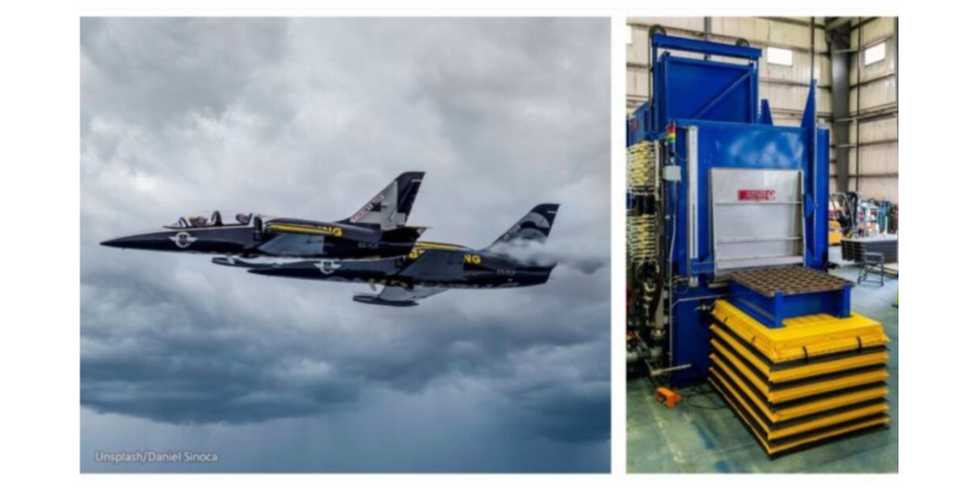
A horizontal spray quench furnace has been completed for C/A Design’s heat treat facility in Exeter, NH. The system will help treat components for the aerospace and defense industry.
The furnace, from Wisconsin Oven, will be used for the solution treatment of aluminum. The system is designed to soak the product load at temperature in the furnace and then a pusher mechanism rapidly moves the load into the spray quench. The spray quench offers reduced distortion in comparison to submersion quenching.
The maximum temperature for this system is 1150°F and it has the capacity to heat a 200 pound aluminum load plus the work grid and product fixture. C/A Design’s new furnace has the capability to meet AMS 2750G, Class 2 furnace and Instrumentation Type D requirements.
Find heat treating products and services when you search on Heat Treat Buyers Guide.com
Earl Good Managing Director at Retech Systems, LLC Source: Retech
Spark plasma sintering technology innovator, GeniCore, will be expanding their North American influence in the powder metal processes market through a partnership with a New York-based metallurgical equipment manufacturer.
GeniCore has established cooperation with Retech Systems, LLC, a SECO/WARWICK Group division, to expand offerings in powder metal processes with spark plasma sintering. “Cooperation with Retech gives us the honor to serve discerning and distinguished customers in the North American market,” commented Marcin Rosiński, CEO at GeniCore.
The spark plasma sintering (SPS) process bonds materials using a combination of pressure and thermal energy applied to materials in a mold. It resembles hot pressing, but the SPS process consumes far less energy and can bond a broader range of materials into novel composites unachievable by other processes.
“[Bringing] SPS into our repertoire and representing its capabilities is a win for Retech, GeniCore, and our customers,” said Earl Good, managing director and president at Retech.
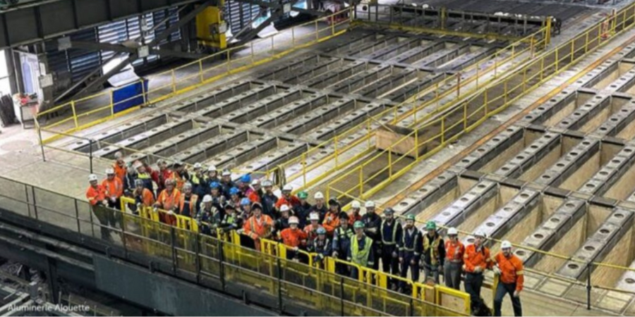
Aluminerie Alouette, based in Sept-Îles, Quebec, Canada, announced several investments in its aluminum smelting operations. These include upgrades to anode baking furnaces as well as a planned installation of new potline technologies that will address waste streams at the site. The Canadian aluminum producer’s new technologies will increase operations and address environmental issues.
Alouette restarted the first firing ramps of its No. 1 (ABF-1) anode baking furnace after a refractory relining project, which was completed with EPCM support from Hatch. With furnace No. 1 restarted, the companies are now beginning work on the restart of a second furnace reline (ABF-2), which is expected to be completed in 2024.
Additionally, Alouette signed two contracts totaling $2.7 million with PyroGenesis Canada Inc. The first contract will address the treatment of spent pot lining (SPL) waste. The technology proposed will use plasma arc thermal treatment to transform the carbonaceous and refractory materials contained in SPL into synthesis gas and aluminum fluoride. The objective of the second contract is to process excess electrolytic bath in a plasma arc thermal treatment plant with the goal of producing aluminum fluoride.
Find heat treating products and services when you search on Heat Treat Buyers Guide.com
In addressing the challenges of modern automated production flow, thru-process temperature monitoring and process validation strategies provide viable options in the automotive heat treat industry. Could they help your operations?
This Technical Tuesday article was composed by Steve Offley, “Dr. O,” product marketing manager, PhoenixTM.It appears in Heat Treat Today’s August 2023 Automotive Heat Treatingprint edition.
The Heat Treat Monitoring Goal
Dr. Steve Offley, “Dr. O”
Product Marketing Manager
PhoenixTM
Source: LinkedIn
In any automotive heat treatment process, it is essential that the heat treat application is performed in a controlled and repeatable fashion to achieve the physical material properties of the product. This means the product material experiences the required temperature, time, and processing atmosphere to achieve the desired metallurgical transitions (internal microstructure) to give the product the material properties to perform it’s intended function.
When tackling the need to understand how the heat treat process is performing, it is useful to split the task up into two parts: focusing on the furnace technology first, and then introducing the product into the mix.
If we consider the furnace performance, we need to validate that the heat treat technology is capable of providing the desired accurate uniformity of heating over the working volume of the furnace for the desired soak time where the products are placed. This is best achieved by performing a temperature uniformity survey (TUS). The TUS is a key pyrometry requirement of the CQI-9 Heat Treat System Assessment (AIAG) standard applied by many automotive OEMs and suppliers.
Traditionally temperature uniformity surveys are performed using a field test instrument (chart recorder or static data logger) external to the furnace with thermocouples trailing into the furnace heating chamber. Although possible, this technique has many limitations, especially when applying to the increasingly automated semi or continuous operations discussed later in this article.
Thru-process Temperature Profiling — Discover the Heat Treat DNA
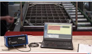
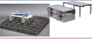
When it comes to heat treatment, the TUS operation gives a level of confidence that the furnace technology is in specification. However, it is important to understand the need to focus on what is happening at the real core of the product from a temperature and time perspective. Product temperature profiling, as its name suggests, is the perfect technique. Thermocouples attached to the part, or even embedded within the part, give an accurate record of the product temperature at all points in the process, referred to as a product temperature profile. Such information is helpful to determine process variations from critical factors such as part size, thermal mass, location within the product basket, furnace loading, transfer rate, and changes to heat treat recipe. Product temperature profiling by trailing thermocouples with an external data logger (Figure 1) is possible for a simple batch furnace, but it is not a realistic option for some modern heat treat operations.
Figure 1. Typical TUS survey set-up for a static batch furnace. PhoenixTM PTM4220 External data logger connected directly to a 9 point TUS frame used to measure the temperature uniformity over the volumetric working volume of the furnace.
Source: PhoenixTM
With the industry driving toward fully automated manufacturing, furnace manufacturers are now offering the complete package with full robotic product loading — shuttle transfer systems and modular heat treat phases to either process complete product baskets or one-piece operations.
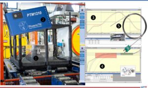
The thru-process monitoring principle overcomes the problems of trailing thermocouples as the multi-channel data logger (field test instrument) travels into and through the heat treat process protected by a thermal barrier (Figure 2).
Figure 2. PhoenixTM thru-process monitoring system. (1) The thermal barrier protects internal multi-channel data logger, (2) the field test instrument, (3) the product thermal profile view, (4) the temperature uniformity survey (TUS), and (5) short nonexpendable mineral insulated thermocouples.
Source: PhoenixTM
The short thermocouples are fixed to either the product or TUS frame. Temperature data is then transmitted either live to a monitoring PC running profile or the TUS analysis software via a two-way RF (radio frequency) telemetry link or downloaded post run.
Although thru-process temperature monitoring in principle can be applied to most heat treat furnace operations, obviously no one solution will suit all processes, as we know from the phrase, “One size doesn’t fit all.”
For this very reason, unique thermal barrier designs are required to be tailored to the specific demands of the application whether temperature, pressure, atmosphere, or geometry as described in the following section.
Product Profiling and TUS in Continuous Heat Treat Furnaces
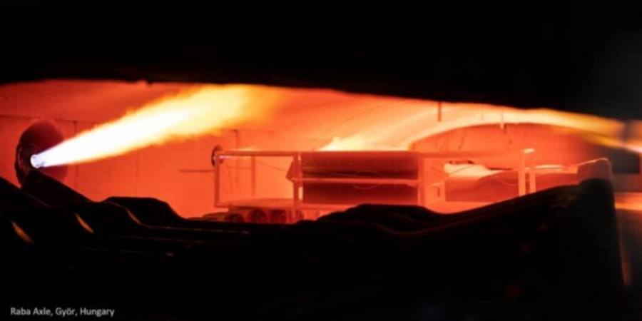
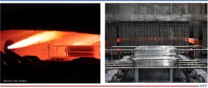
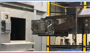
Thru-process product temperature profiling and/or surveying of continuous furnace operations, unlike trailing thermocouples, can be performed accurately and safely as part of the conventional production flow allowing true heat treat conditions to be assessed. As shown in Figure 3, surveying of the furnace working zone can be achieved using the plane method. A frame attached to the thermal barrier positions the TUS thermocouples at designated positions relative to the two dimensional working zone (furnace height and width) as defined in the pyrometry standard (CQI-9) during safe passage through the furnace (soak time).
Figures 3. Temperature uniformity survey of a continuous furnace using the plane method applying the PhoenixTM thru-process monitoring system. The data logger travels protected in a thermal barrier mounted on the TUS frame performing a safe TUS at four points across the width, which is impossible with trailing thermocouples.
Source: : Raba Axle, Györ, Hungary
Sealed Gas Carburizing and Oil Quench Monitoring
For traditional sealed gas carburizing where product cooling is performed in an integral oil quench, the historic limitation of thru-process temperature profiling has been the need to bypass the oil quench and wash stations.
In such carburizing processes, the oil quench rate is critical to both the metallurgical composition of the metal and to the elimination of product distortion and quench cracks, and so the need for a monitoring solution has been significant. Regular monitoring of the quench is important as aging of the oil results in decomposition, oxidation, and contamination of the oil, all of which degrade the heat transfer characteristics and quench efficiency.
To address the process challenges, a unique barrier design has been developed that both protects the data logger in the furnace (typically 3 hours at 1700°F/925°C) and during transfer through the oil quench (typically 15 minutes) and final wash station.
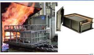
Figures 4. PhoenixTM thru-process temperature profiling system monitoring the core temperature of automotive parts in a traditional sealed gas carburizing furnace with integral oil quench. (left) System entering carburizing furnace in product basket. (right) Thermal barrier showing outer structural frame and sacrificial insulation blocks protecting inner sealed thermal barrier housing the data logger.
Source: PhoenixTM
The key to the barrier design is the encasement of a sealed inner barrier (Figure 4) with its own thermal protection with blocks of high-grade sacrificial insulation contained in a robust outer structural frame. The innovative barrier offers complete protection to the data logger allowing product core temperature monitoring for the complete heat treat process under production conditions.
Low Pressure Carburizing with High Pressure Gas Quench
In the current business environment, an attractive alternative to the traditional sealed gas carburizing application for both energy and environmental reasons is low pressure carburizing (LPC). Following the vacuum carburizing process, the product is transferred to a sealed high-pressure gas quench chamber where the product is rapidly gas cooled using typically N2 or Helium at up to 20 bars.
Such technology lends itself to automation with product baskets being transferred by shuttle drives and robot loading mechanisms from chamber to chamber in a semi-continuous fashion. The sequential processing (with stages often being performed in self-contained sealed chambers) can only be monitored by the thru-process approach where the system (thermal barrier protected data logger) is self-contained within the product basket or TUS frame.
In such processes the technical challenge is twofold. The thermal barrier must be capable of protecting against not only heat during the carburizing phase, but also very rapid pressure and temperature changes inflicted by the gas quench. To protect the thermal barrier in the LPC process with gas quench, the barrier construction needs to be able to withstand constant temperature cycling and high gas pressures. The design and construction features include:
Metal work: 310 stainless steel to reduce distortion at high temperature combined with internal structural reinforcement
Insulation: ultra-high temperature microporous insulation to minimize shrinkage problems
Rivets: close pitched copper rivets reduce carbon pick up and maintain strength
Lid expansion plate: reduces distortion during rapid temperature changes
Catches: heavy duty catches eliminating thread seizure issues
Heat sink: internal heat sink to provide additional thermal protection to data logger
During the gas quench, the barrier needs to be protected from Nitrogen N2 (g) or Helium He(g) gas pressures up to 20 bar. Such pressures on the flat top of the barrier would create excessive stress to the metal work and internal insulation or the data logger. Therefore, a separate gas quench deflector is used to protect the barrier. The tapered top plate deflects the gas away from the barrier. The unique design means the plate is supported on either four or six support legs. As it is not in contact with the barrier, no force is applied directly to the barrier and the force is shared between the support legs.
In LPC technology further monitoring challenges are faced by the development of one piece flow furnace designs.
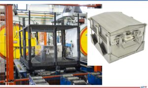
Figures 5. (left) Thermal barrier being loaded into LPC batch furnace with TUS frame as part of temperature uniformity survey. (right) Thermal barrier shown with independent quench deflector providing protection during the high pressure gas quench.
Source: PhoenixTM
New designs incorporate single piece or single product layer tray loading into multiple vertical heat treat chambers followed by auto loading into mobile high pressure quench chamber. Miniturization of each separate heat treat chamber limits the space available to the monitoring system. The TS02-128-1 thermal barrier has been designed specifically for such processes utilizing the compact 6 channel “Sigma” data logger allowing reduction of the footprint of the system to fit the product tray and reduce thermal mass. With a height of only 128 mm/5 inch and customized independent low height quench deflector, the system is suitable for challenging low height furnace chambers and offers 1 hour protection at 1472°F/800°C in a vacuum.
Figure 6. (left) Low profile TUS system (TS02-128-1 thermal barrier six channel Sigma data logger) designed with TUS surveying individual one-piece flow heat treatment LPC furnace chambers (right) Thermal barrier shown with optional low profile gas quench deflector.
Source: PhoenixTM
In modern rotary hearth furnaces (Figure 7), temperature profiling using trailing thermocouples is impossible as the cables would wind up in the furnace transfer mechanism. Due to the central robot loading and unloading and elimination of charging racks/baskets, the use of a conventional thru-process system would also be a challenge.
Figure 7. A modern rotary hearth furnace.
Source: PhoenixTM
To eliminate the loading restrictions, a unique thermal barrier small enough to fit inside the cavity of the engine block and allow automated loading of the complete combined monitoring system and product has been developed. To optimize the thermal performance of the thermal barrier with such tight size constraints, a phased evaporation technology is employed. Thermal protection of the high temperature data logger is provided by an insulated water tank barrier design keeping the operating temperature of the data logger at a safe 212°F/100°C or less. The system allowed BSN Thermoprozesstechnik GmbH in Germany to commission the furnace accurately and efficiently and thereby optimize settings to not only achieve product quality but also ensure energy efficient, cost effective production.
Summary
Thru-process product temperature profiling and surveying provide a versatile, accurate, and safe solution for monitoring increasingly automated, intelligent furnace lines and the means to understand, control, optimize, and certify your heat treat process.
About the author:
Dr. Steve Offley, “Dr. O,” has been the product marketing manager at PhoenixTM for the last five years after a career of over 25 years in temperature monitoring focusing on the heat treatment, paint, and general manufacturing industries. A key aspect of his role is the product management of the innovative PhoenixTM range of thru-process temperature and optical profiling and TUS monitoring system solutions.
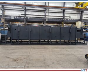
The first of five new mesh belt temper furnaces was shipped from Michigan manufacturer to the southern U.S. The second and third furnaces are ready for the next phases of production, and they all will be used for preheating and tempering of steel bar stock.
Premier Furnace Specialists, Inc./BeaverMatic has scheduled the first installation for the last week of August. The remaining four will be completed and installed through January 2024. These furnaces are natural gas fired with an operating temperature of 1600°F. They have thirty-six inch wide mesh belts capable of 2000 lbs per hour. The furnaces are all operated through a 23.8” HMI color touch screen interface.
Mesh belt furnace from Premier Furnace Specialists, Inc./BeaverMatic Source: Premier Furnace/BeaverMatic
“We built them a similar furnace in 2022,” commented Steve Ignash, sales engineer at Premier. “The [latest] system was designed, built, and tested at our new 40,000 square foot facility in Farmington Hills, MI.”
Find heat treating products and services when you search on Heat Treat Buyers Guide.com
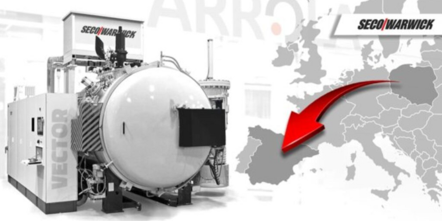
A service hardening plant in Spain will receive a vacuum furnace that is adapted to the aviation standard to perform production for this industry. The furnace will increase the company’s efficiency when hardening larger-dimension elements.
"The Vector [furnace] will enhance and increase the hardening processing capacity and will improve process efficiency," comments Maciej Korecki, vice president of the Vacuum Segment at SECO/WARWICK Group, a heat treat furnace supplier with North American locations. "The advantage of this product is a large working space with the capacity to adjust to an oversized load, utilizing the advantages of a circular heating chamber."
Find heat treating products and services when you search on Heat Treat Buyers Guide.com
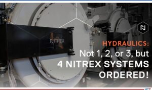
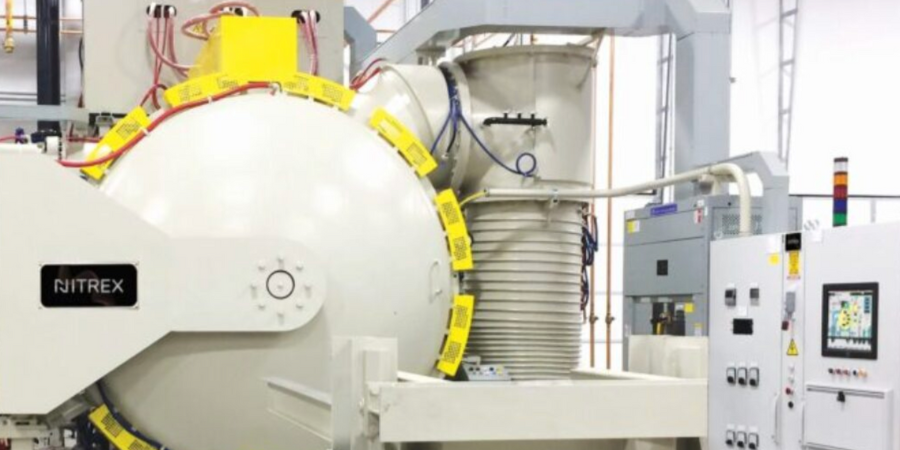
A set of nitriding/nitrocarburizing systems has been installed for a European hydraulics manufacturer. The furnaces help produce components for hydraulic pumps and motors and strengthen the company’s in-house heat treatment capabilities.
The furnaces are from Nitrex – a company based in North America with international locations. This is the second set of systems from the same manufacturer. These systems primarily serve to nitride/nitrocarburize pieces made from various steels and alloys and will help meet the growing demand for hydraulic components.
Hydraulics systems expand heat treat capabilities Source: Nitrex
“The nitriding/nitrocarburizing furnaces have [. . . integrated] seamlessly into our customer’s operations,” commented Mark Hemsath, vice president of sales, furnaces & heat treating services at Nitrex.
Find heat treating products and services when you search on Heat Treat Buyers Guide.com
Discover expert tips, tricks, and resources for sustainable heat treating methods Heat TreatToday’srecent series. Part 4, today’s tips, covers induction heating, quench, and insulation tips. We’ve added resources towards the end of today’s post for further enrichment.
This Technical Tuesday article is compiled from tips in Heat TreatToday’sMay Focus on Sustainable Heat Treat Technologiesprint edition. If you have any tips of your own about induction and sustainability, our editors would be interested in sharing them online at www.heattreattoday.com. Email Bethany Leone at bethany@heattreattoday.com with your own ideas!
1. Tips for Induction Hardening
Contact us with your Reader Feedback!
What are the benefits of induction hardening? Here are a few:
Saves space: Induction hardening requires minimum space required in comparison with furnaces
Saves energy: Induction heating equipment does not need to be kept running when not in use
Clean: Induction heating equipment requires no combustion gases
Energy-efficient: Only a small proportion of the material needs to be heated
Minimize deformation: Induction hardening requires no applied force
Save maintenance costs: Inductor coils have a long life, reducing the need for maintenance
Source: Humberto Torres Sánchez, Chief Metallurgist, ZF Group
2. Insulation = Key for Energy Savings in Vacuum Furnaces
Look for insulation quality in your next vacuum furnace.
Source: NITREX
Improvements in insulation materials are also contributing to greater energy efficiency of vacuum furnaces. Most furnaces on the market today have a 1” (25.4 mm) graphite board with bonded Grafoil and two layers of graphite felt. However, the insulation performance of a 1” (25.4 mm) graphite board is about 25% less efficient than a 1” (25.4 mm) graphite felt. For processes that require high operating temperatures, typically over 2,200°F (1,204°C), an all graphite felt that is 2” or 2.5” thick (50.8 mm or 63.5 mm) minimizes heat loss inside the hot zone. Efficiency gains of up to 25% are possible over the standard 1” (25.4 mm) board and 1” (25.4 mm) graphite felt insulation and an even greater gains at higher operating temperatures. To safeguard the graphite felt from mechanical harm and localized compression, these thicker all-graphite felt insulation configurations are usually covered with a carbon fiber composite (CFC) sheet about 0.050” (1.27 mm) thick.
Fuel efficiency (and the stringent requirement for passenger safety) has raised the bar for the automotive industry to procure steel with high strength, hardness, and ability to fabricate. Reduction of weight requires lighter cars with thinner body material which can absorb impact. These dual contradictory properties of high hardness material which can be easily shaped can normally be achieved either by heat treat or through addition of alloys. These two processes are described below.
Normal heat treatment to produce small grains in the material will increase the hardness in steel but also create a propensity to fracture. Thus, a process known as quench and partition — where carbon diffusion from martensite to retained austenite to stabilize the latter — has been introduced. Further verification and prediction of the phases has been conducted using thermodynamics modeling for phase characteristics by Behera & Olsen at Northwestern University, Materials Science and Engineering.
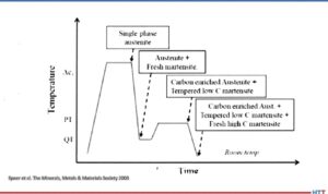
The process starts with full automatization (or in some cases intercritical annealing) followed by fast quench to a defined quench temperature (QT) between the martensite start, Ms, and martensite finish, Mf, temperature. The steel is then reheated to the partition temperature (PT) and held there for a certain partition time followed by a quenching step again to room temperature, as shown in the image.
Quench and partition process
Source: Speer et al. The Minerals, Metals, & Materials Society 2003
The quenching step establishes the largely martensite matrix while the partition step helps stabilize the retained austenite by carbon partitioning. During the holding step, carbon diffuses from martensite to retained austenite and thus improves its stability against subsequent cooling or mechanical deformation. The final microstructure consists predominantly of tempered martensite and stabilized retained austenite with possibly a small amount of bainite formation and carbide precipitation during the partition step and fresh martensite formation during final quenching.
The other process to achieve high hardness and high ductility is by alloy addition in carbon steel. Over, 2,000 different types of steel exist. A new type of steel that is extremely strong, but simultaneously ductile is used in the automotive industry. Small quantities of elements like vanadium or chrome in steel promotes ductility. They are not brittle; however, up until now they have not been strong enough to enable the construction of car bodies with thinner sheets.
In the crystals of steels, the atoms are more or less regularly arranged. Steels become particularly ductile though if they can switch from one structure to another. This is because this process allows energy absorption, which can then no longer initiate any damage in the material. In a car body or other steel components, tiny areas then alternate with the two different atom arrangements.
Ductile steels have two coexisting crystal structures. The search produced an alloy made from 50% iron, 30% manganese and 10% respectively of cobalt and chrome (Max Planck Institutes).
The trend of automotive companies in recent years has been to bet on greener ways of transportation to reduce the carbon footprint that we have left over the last decades.
In today’s article, Humberto Torres Sánchez, quality coordinator at ZF Group makes the point that as heat treatment professionals, it is our duty to look for viable alternatives that do not affect the quality of heat treated products, remain safe, and above all reduce our carbon footprint. Read this original content release in Heat TreatToday’sAugust 2023 Automotive print edition.
Humberto Torres Sánchez
Quality Coordinator
ZF Group
Source: ZF Group
At ZF Group, we are committed to this challenge with many heat treat efforts employing induction. In fact, the decision to incorporate induction heat treatment initially was made to reduce operating costs, improve part and plant cleanliness, and improve layout, as opposed to conventional hardening. With induction heat treat, we are able to use less quench media — avoiding waste — and work to improve the efficiency of induction heat treatment in our facilities.
As a result, we’ve seen major improvements. These include streamlined processes by reducing electricity consumption, reduction of air emissions, and the most important, in my opinion, the total elimination of the use of oil for tempering when using environmentally friendly tempering media.
But improvements didn’t happen overnight. It took at least two years to fully incorporate induction for our automotive parts production, and streamlining the processes came about in stages. Three key steps to incorporate induction for our in-house heat treat operations were:
Achieve the metallurgical characteristics required by drawings and making use of the parameters of the inductor machine (e.g., power, heating speed, quench flow).
Validate the product with functional tests (dynamic and static).
To accommodate all of these new changes, we must add continuous training with personnel. This is essential to avoid reprocessing parts, as well as to reinforce the importance of analytical and critical thinking in favor of ecological improvement.
Another important element to move towards sustainable automotive processing solutions is employing the use of low pressure carburizing (LPC) instead of conventional carburizing. Greater homogeneity of metallurgical characteristics such as hardness and effective case depth can be achieved. Using LPC, we can reduce air emissions and eliminate quenching oil.
Making automotive heat treat operations environmentally friendly is an all encompassing endeavor.
Humberto Torres Sánchez
Making automotive heat treat operations environmentally friendly is an all encompassing endeavor. In transitioning away from oil quenchants in heat treat operations, we have been able to use cleaning detergents that are less corrosive, and which have a longer half-life within the process. In the future, the processes the industry uses will move to more environmentally friendly chemicals, and the correct preventive maintenance to avoid liquid leaks to eliminate soil contamination will be made.
Through all these efforts, ZF Group is committed to a greener mobile future.
About the Author: Humberto Torres Sánchez is the quality coordinator at ZF Group and is responsible for the quality department, laboratories, and special processes (heat treatment and welding). Involved in a variety of plant operations, he acts as the lead auditor for both CQI-9 and CQI-15. Learn more about Humberto from his 40 Under 40 Class of 2022profile.
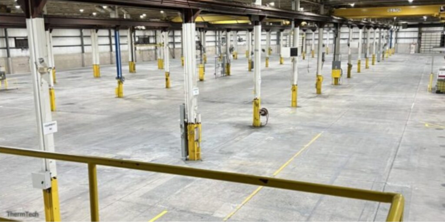
A heat treat company based in Waukesha, WI, has expanded with a 95,000 square foot building in New Berlin, WI. The New Berlin facility is seven miles from their Travis Road campus.
Steve Wiberg and Mary Wiberg Springer, owners of ThermTech, share that the plant’s square footage will be 270,000. The new space will be used for the company’s expansion. The new facility will allow the heat treater to continue to meet their clients’ needs as they expand their core offerings: hardening, tempering, surface heat treatment, carburizing, vacuum treatments, annealing, press quenching, austempering, and aluminum heat treatment.
Find heat treating products and services when you search on Heat Treat Buyers Guide.com