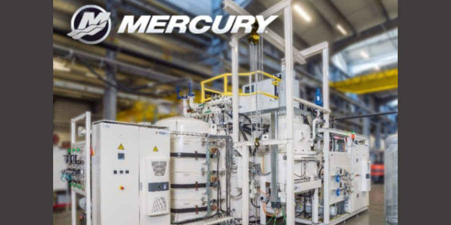
Mercury Marine of Fond du Lac, Wisconsin, recently launched a plan to upgrade its heat-treating capabilities with a move to the low-pressure carburization and high-pressure gas quench system. The new plan incorporates completely automated vacuum heat treating systems.
In the partnership with ECM Technologies, the Nano vacuum heat treating system (pictured above) incorporates 20 bar nitrogen gas quenching along with low pressure carburizing (aka vacuum carburizing). The Nano will operate several different carburizing, hardening, and spheroidizing processes simultaneously.
This change marks a departure from Mercury’s traditional atmospheric carburization and oil quench system while benefiting from advantages that come with vacuum processing:
Applies vacuum heat treating in lieu of traditional atmosphere (elimination of intergranular oxidation & highly repeatable process with consistent results)
Employs preventive maintenance planning, remote system status access, and facility information systems integration
Relocates heat treat from a secondary location to the clean, controlled environment of the machining centers
Converts to small batch processing principles to maximize process efficiency
State-of-the-art growth with ECM’s advanced system automation and robot capability with load building and breakdown
Controls downstream operations by matching incoming dunnage with exiting workpieces
Takes advantage of vapor and vacuum-based pre-cleaning technology to remove multiple machining lubricants
Incorporates cryogenic and tempering processes within the automated system
The system uses all CFC workload fixtures and ECM’s advanced automation fixture tracking to maintain a precise cycle count to know fixture life. For Mercury, this significantly reduces energy consumption and process cost per piece. Additionally, the vacuum process takes their heat treatment to a near-zero emissions for drivetrain components processed within the system.
In June, we spent a good deal of time discussing a simple pressure switch to emphasize the many considerations that are necessary for proper installation. Now we will expand the discussion to how the switch works and what steps we can take to detect a failure that is likely to occur sometime in the future.
This column appeared in Heat TreatToday’s2021 Automotive August print edition. John Clarke is the technical director at Helios Electric Corporation and is writing about combustion related topics throughout 2021 for Heat TreatToday.
John B. Clarke Technical Director Helios Electric Corporation Source: Helios Electric Corporation
A pressure switch is a Boolean device — it is either on or off — so how can we evaluate its performance in a manner where a potential failure can be detected before it occurs? The simple answer is time — how long does it take for the switch to respond to the condition it is intended to sense? What is the period between starting an air blower and the pressure switch closing? Has this time changed? Is a change in this time period to be expected, or does it portend a future failure?
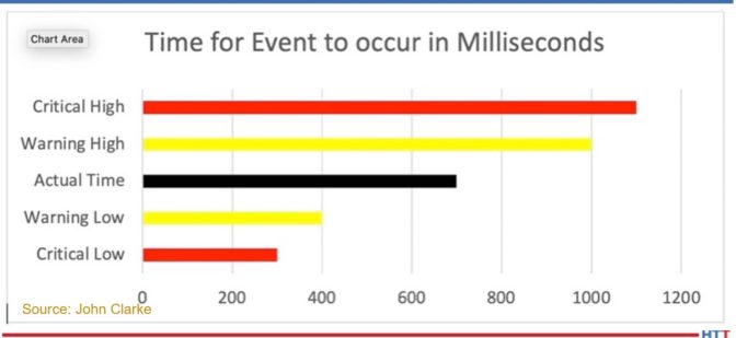
A simple approach to evaluating this pressure switch’s time is to create predetermined limits — if the switch responds either too rapidly or too slowly — an alarm is set and the operator is alerted. Graph 1 illustrates this approach.
In Graph 1, the black band represents the time between the action (the start of the air blower) and the pressure switch closing. There is a warning band (yellow) — both high and low — that provides the early warning of a system performance problem. There is also a critical band (red) — both high and low — that provides the point at which the feedback for the pressure switch is determined to be unreliable. If the switch is part of a safety critical interlock, the system should be forced to a safe condition (in the case of a combustion system, with the burner off and a post purge being executed) if required.
Graph 1
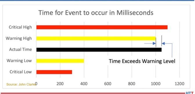
Graph 2 depicts when a switch closing time exceeds the warning level. It could be the result of a problem with the blower and/or the pressure switch, but the deviation is not sufficiently large as to undermine confidence in the switch’s ultimate function.
Programmatically, if the time exceeds the warning band, and an alarm is registered, the responsible maintenance person is notified. If that is in the warning band, it can be addressed as time allows.
Graph 2
The warning bands give us the crystal ball to potentially see a problem before it causes a shutdown. As it is continuously monitored by the programmable logic controller (PLC), it may provide an increased level of safety, but that is dependent on a number of factors that are beyond the scope of this article.
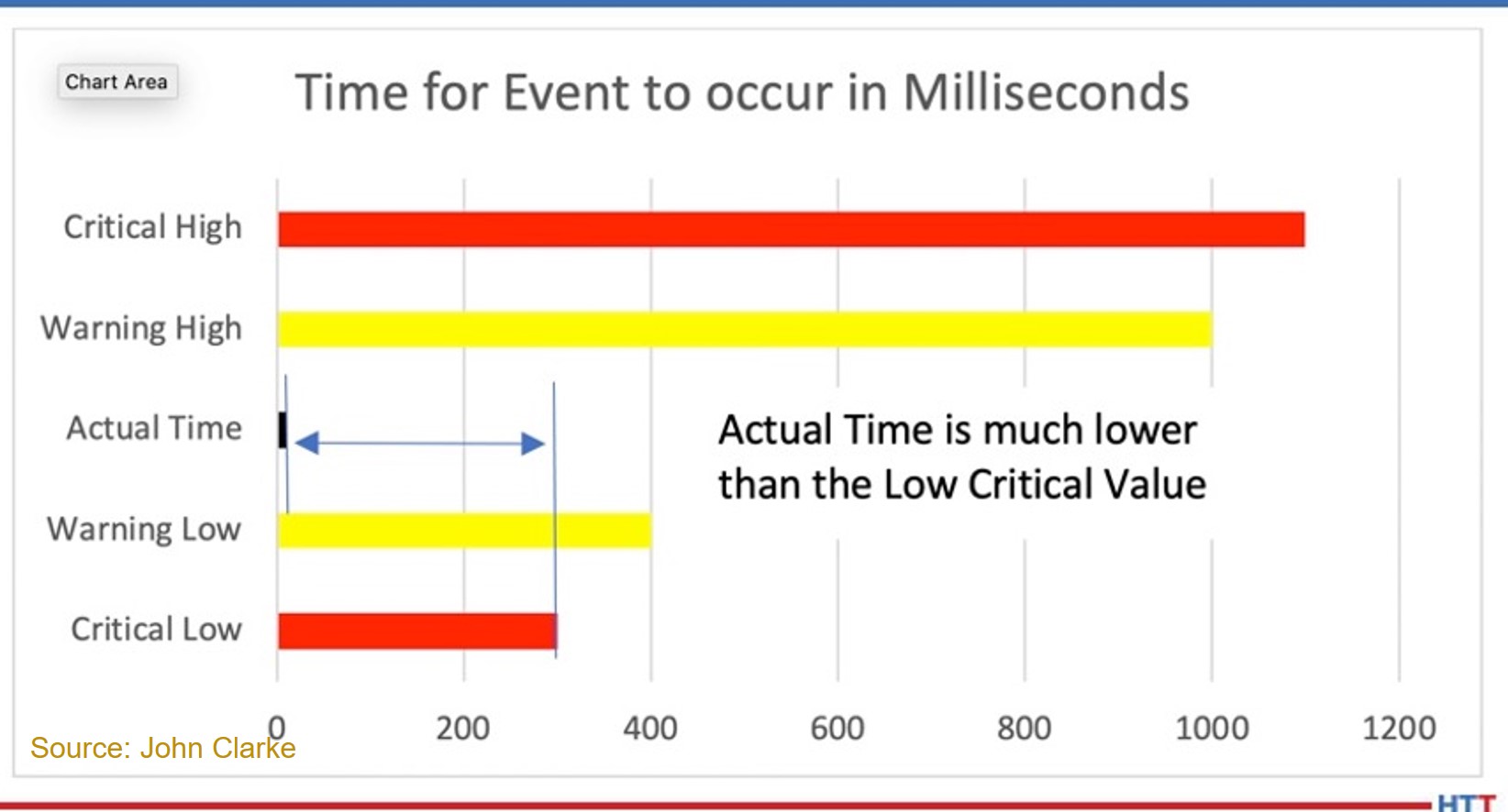
The switch can be not only too slow to respond: an unusually fast response is a reason to be concerned as well. It could be that the pressure switch setpoint has been set too low — so low that it no longer provides useful feedback. Graph 3 is an example with an unusually fast response.
If the time is less than the “Critical Low” preset value, the switch’s feedback is determined to be unreliable. In this case, the setpoint may have been changed during a maintenance interval or even worse — the switch may be jumpered (this assumes we have an interlock string wired in series). The critical values are NOT intended to provide forward looking estimates of required maintenance — they are simply an enhanced safety measure.
This scenario assumes that the response of a component is consistent. In our example of a pressure switch monitoring an air blower, we can assume the time the blower required to reach full speed, the time for a pressure rise time in the air piping, and the responsiveness of the switch is consistent. These time intervals may not be consistent. The air supplied to the blower could be sourced from outside the building (temperate climate), which could cause air density changes between a cool, dry day and a hot, moist day. In this instance, what can be done to detect a failure?
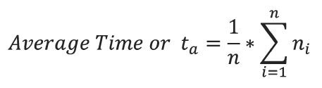
An approach where we see fluctuations in the timing even in instances where all the components are operating properly would be to run a moving average of the time based on the last n operations. Then we compare the moving average to the last time and confirm that any change falls within a specific range.
Step 1 would be to average the last n values for the time required for the switch to trip. Then compare this value (ta) to the last time and see if the deviation exceeds the preset values. Let us assume if the time varies by more than 20% a warning should be issued to the maintenance staff.
Now this method will accommodate rapid fluctuations – but if the performance of the component degrades in a near linear fashion, this formula will not detect a premature failure.
An alternate approach would be to execute this routine on the first n cycles, as opposed to continuously updating the average. Using this method, the performance of the specific component is captured. Or this averaging can be executed on demand or based on the calendar or Hobbs timer.
These concepts are far from new, and it has only been because of the recent expansion in PLC memory storage capacity and processing power that it has been reasonable to perform this analysis on dozens of components on a furnace or oven. Remember, it is a shame to waste PLC processing time and memory!
One or more of these approaches, or similar approaches analyzing time, can indeed be a crystal ball that gives us warning of any of a number of potential failures — warning before a system shutdown is required.
About the Author:
John Clarke, with over 30 years in the heat processing area, is currently the technical director of Helios Electric Corporation. John’s work includes system efficiency analysis, burner design as well as burner management systems. John was a former president of the Industrial Heating Equipment Association and vice president at Maxon Corporation.
Want a free tip? Check out this read of some of the top 101 Heat TreatTips that heat treating professionals submitted over the last three years. These handy technical words of wisdom will keep your furnaces in optimum operation and keep you in compliance. If you want more, search for “101 heat treat tips” on the website! This selection features 8 tips to make sure your operations are clean and pure.
Also, in this year’s show issue, Heat TreatToday will be sharing Heat TreatResources you can use when you’re at the plant or on the road. Look for the digital edition of the magazine on September 13, 2021 to check it out yourself!
Oil and Water Don’t Mix
Keep water out of your oil quench. A few pounds of water at the bottom of an IQ quench tank can cause a major fire. Be hyper-vigilant that no one attempts to recycle fluids that collect on the charge car.
(Combustion Innovations)
Dirt In, Dirt Out!
Parts going into the furnace should be as clean as possible. Avoid placing parts in the furnace that contain foreign object debris (FOD). FOD on work surfaces going into the furnace will contaminate the furnace and the parts themselves. Dirty work in, dirty work out. FOD comes in many forms. Most common: oil, grease, sand in castings or grit blasting operations, and metal chips that generally originate from the manufacturing process before the parts are heat treated. It could also be FOD from the shipping process such as wood or plastic containers used to ship the parts.
(Solar Manufacturing)
Remove Particulates
Adding a strong magnetic filter in line after the main filtration system is an effective way to remove fine, metallic particulates in an aqueous quench system.
(Contour Hardening, Inc.)
Seal Away Dirt or Dusty Environments
Use a sealed enclosure or alternative cooled power controllers for dirty and dusty environments. For heavy dirt or dusty environments, a sealed cabinet with air conditioning or filters is recommended. Alternatively, select a SCR manufacturer that offers external mount or liquid cooled heatsinks to allow you to maintain a sealed environment in order to obtain maximum product life.
(Control Concepts)
Copper as a Leak Check
If maintaining dew point is a problem, and it’s suspected that either an air or water leak is causing the problem, run a piece of copper through the furnace. Air will discolor the copper; water will not.
(Super Systems, Inc.)
Oxygen Contamination Sources
A common source of oxygen contamination to vacuum furnace systems is in the inert gas delivery system. After installation of the delivery lines, as a minimum, the lines should be pressurized and then soap-bubble tested for leaks. But even better for critical applications is to attach a vacuum pump and helium leak detector to these lines with all valves securely closed, pull a good vacuum, and helium leak check the delivery line system. Helium is a much smaller molecule than oxygen and a helium-tight line is an air-tight line. Also, NEVER use quick disconnect fittings on your inert gas delivery system to pull off inert gas for other applications unless you first install tight shut-off valves before the quick disconnect. When the quick disconnect is not in use, these valves should be kept closed at all times. (Though the line is under pressure, when you open a back-fill valve to a large chamber, the line can briefly go negative pressure and pull in air through a one-way sealing quick disconnect valve.)
(Grammer Vacuum Technologies)
Container Clarity Counts!
Assure that container label wording (specifically for identifying chemical contents) matches the corresponding safety data sheets (SDS). Obvious? I have seen situations where the label wording was legible and accurate and there was a matching safety data sheet for the contents, but there was still a problem. The SDS could not be readily located, as it was filed under a chemical synonym, or it was filed under a chemical name, whereas the container displayed a brand name. A few companies label each container with (for instance) a bold number that is set within a large, colored dot. The number refers to the exact corresponding SDS.
(Rick Kaletsky, Safety Consultant)
Discolored Part—Who’s to Blame?
If your parts are coming out of the quench oil with discoloration and you are unsure if it is from the prewash, furnace, or oil quench, you can rule out the quench if the discoloration cannot be rubbed off. Check this before the part is post-washed and tempered.
Other possible causes:
Can be burnt oils as parts go through the quench door flame screen
Poor prewash
Furnace atmosphere inlet (particularly if it is drip methanol)
(AFC-Holcroft)
Check out these magazines to see where these tips were first featured:
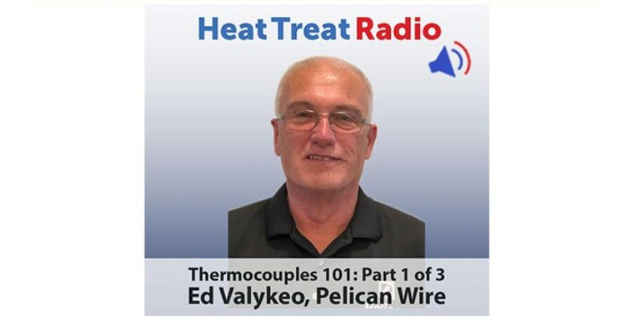
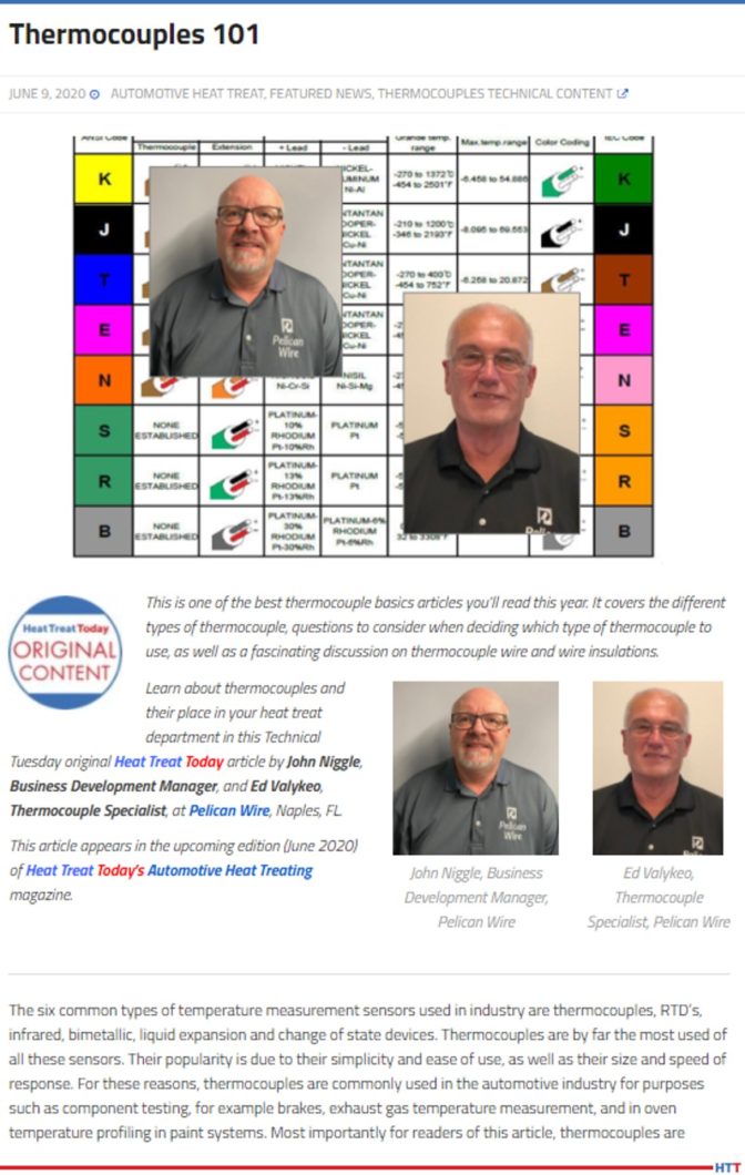
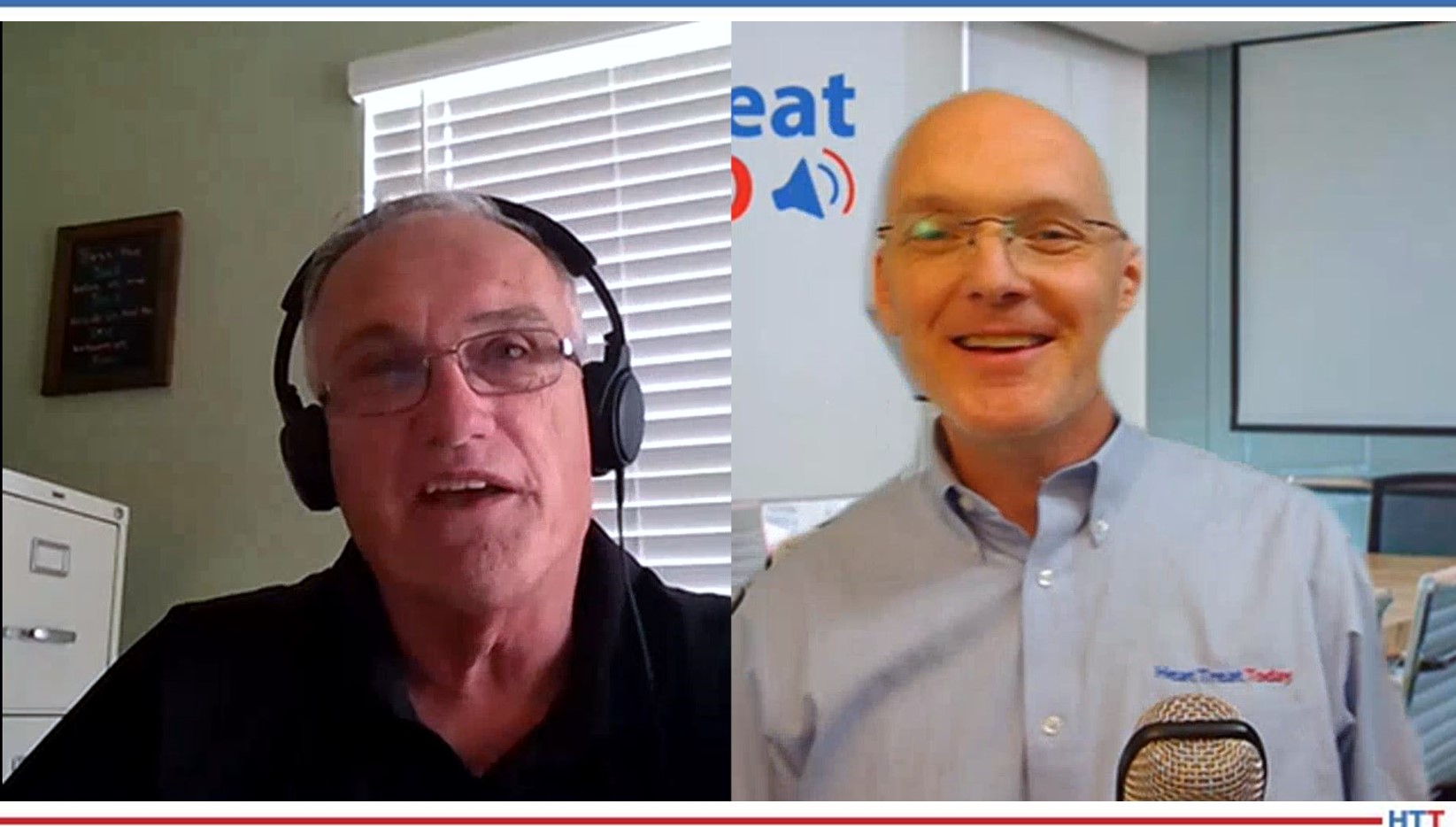
Heat TreatToday publisher Doug Glenn sits down with Ed Valykeo from Pelican Wire in the first of a three-part series on all-things thermocouples. This first episode covers the history, types, vocabulary, and other basics of understanding how thermocouples work.
Below, you can either listen to the podcast by clicking on the audio play button, or you can read an edited transcript.
The following transcript has been edited for your reading enjoyment.
Doug Glenn (DG): Ed, why don't you take a minute, as we typically do on these interviews, to talk briefly about you and your background especially your qualifications for talking about thermocouples.
CLICK the image to access the article!
Ed Valykeo (EV): I've actually been in the wire and cable industry for a little over 40 years now. I actually first started in the industry as, well maybe not a grunt, but certainly I was called a “melter's helper.” I worked at a company called Hoskins Manufacturing in Ann Arbor, Michigan where we actually melted the raw materials to make thermocouple wire, resistance wire, and a whole host of other things. I was actually the guy that, after we got done pouring that molten metal into the molds to make the ingots, was cleaning up all the mess that happens after you pour and you're pulling those ingots.
That's really where my career started, with Hoskins. As a matter of fact, it kind of ran in the family. My dad retired at Hoskins with 42 years of service with Hoskins, so it was kind of a natural progression that, eventually after I got out of the service, I ended up joining Hoskins. I was there about 18 years at Hoskins Manufacturing, again, starting out right at the bottom. I worked my way up to becoming an associate engineer working in the R&D department. That's where my career really started focusing a little more on thermocouples. I enjoyed working with thermocouples. We were developing some new products using thermocouple wire and things like that.
Ever since then, I've kind of stayed in thermocouple arena at some of the other places I've worked. After I left Hoskins, I started working for companies that insulated wire. So, we were taking the wire, like we made at Hoskins, and we were putting a whole host of insulations on it from ceramic braid to extruded products and things like that. And, again, both the companies, and even the one I'm currently employed with at Pelican, but before that I was working for a company out in New Hampshire called PMC, are real similar, it's just we insulated wire. So, we purchased the raw materials (raw wire from Hoskins or whoever) and then insulated it.
DG: For the unbaptized in this topic, what are thermocouples, how do they work, how do they come about, and then are the modern-day thermocouples any different than the thermocouples of old?
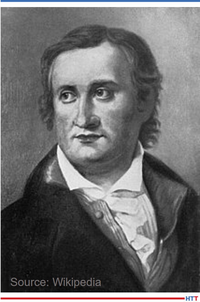
EV: I always start out with a little bit of history about thermocouples, whenever I'm talking about them, just to give people background. Thermocouples were introduced in the early 1800's with the most significant developments taking place in Europe.
One of the very first gentleman that worked on it was Alessandro Volta. You can probably recognize the name because Volta actually is the volt, today, which everybody recognizes, not just with thermocouples but, obviously, in the electrical industry too. He basically built a couple thermopiles using metals, silver and zinc and some cloth in between them, soaking them in salt water, and discovered that it would produce a voltage. That's kind of how it got started. The significance of that discovery was that there is a source of steady and reliable current flow from using dissimilar metals and saltwater and things like that.
Thomas Johann Seebeck, Baltic German physicist, who, in 1822, found the relationship between heat and magnetism.
Over the years, many others have experimented with the phenomenon. Probably the most famous, anybody that's in the thermocouple industry will hear it a lot, in 1821, Thomas [Johann] Seebeck announced that he had discovered that when two dissimilar metals were placed in a closed loop and one of those junctions was exposed to a change in temperature, electrical current was produced. This production of the electromotive force and electromatic force is the electric current is known as "the Seebeck effect" or "Seebeck coefficient." It was, obviously, much later, before everything was understood and correct mathematics, but Seebeck's name will always and forever be associated with the discovery of thermoelectricity and thermocouples. Again, even to this day, even ASTM books reference Seebeck coefficient.
Some other gentlemen that we involved, again you'll recognize some of these, were Michael Faraday, Georg Ohm, Claude Pouillet, and Antoine [César] Becquerel. It was Becquerel, actually, that suggested using Seebeck's discovery for measuring high temperatures. He proposed the strength of the current generated was proportional to the change in temperature in exactly the principle behind the thermocouple. We're measuring temperature, whether it's 200 degrees or 2300 degrees. That's how the modern day thermocouple got started way back in the early 1800's.
DG: And the modern-day thermocouples are, essentially, the same as that? Have there been any major changes?
EV: In reality, Type J was the first thermocouple to really be experimented with. After Type J, then some additional thermocouple types came on board. People experimented with other metallurgical compositions to develop different millable outputs.
DG: Let me understand: Type J, what that basically the first type of thermocouple that was developed?
EV: Let me back up a little bit. Actually, the early metal thermocouples were based on what we can call noble metals. Noble metals are rare earth elements such as platinum, rhodium, tungsten and uranium. The problem with the noble metals is that noble metals are much more expensive than our base metal thermocouples, or what we call base metal thermocouples, today. Base metal thermocouples, today, typically the compositions are just a handful of elements. You have iron, nickel, chromium, copper and things like that, which is considerably cheaper than the noble metals, the platinum and rhodium and things like that.
DG: I want to learn this history a little bit, because it's just kind of fascinating to me. So, the very first ones were made of noble metals, primarily. So, they would put those together and then, basically, we said, "This is great but it's way too expensive. Can we get the same effect, if you will, (the difference in voltage, or whatever, between dissimilar metals), if we use a little less expensive metals?"
EV: Right.
DG: You’ve said there is a difference voltage when there's a difference in temperature.
EV: The EMF (electromotive force) generated by the thermocouple is linear. So, at 200 degrees, it produces this amount of voltage, at 300 degrees, it produces this much. All the thermocouples are, basically, the same principle. It's very linear. That's one thing that is good about a thermocouple- the EMF output is linear. You aren't producing a millivoltage at 200 degrees and then at 300 it goes down and then at 500 it goes back up; it's linear proportional to the temperature.
CLICK the image to access the article!
DG: I have heard in the past, and you mentioned it here, maybe we can discuss it a little bit: noble metal versus base metal. Obviously, we know noble metals, you mentioned what those are. Those are expensive; they work to do the same thing. Base metals, though, tend to be what? Which metals?
EV: As I already mentioned, the nickel, chromium, copper, and others.
DG: And those are, in fact, just less expensive, right? Essentially, they do the same thing but they're less expensive.
EV: Exactly. But, there are some other differences, too, between the noble metals and the base metal thermocouples. When you're talking noble metals, the platinum and the rhodium, and things like that, they can handle much higher temperatures than even the base metal thermocouples.
DG: I'm going to make an assumption, but probably the vast majority of the thermocouples used in the heat treat industry are probably base metal, although, I'm sure they've got some specialized ones for high temperature, which probably jump into noble metals.
EV: Absolutely. A lot of the base metal thermocouples are used in the load sensors where they're putting multiple sensors in and then the oven may be controlled by a noble metal.
DG: The different types of thermocouples. You mentioned, and I've forgotten the letter already, that there are different types. Was it Type J you mentioned?
EV: Yes, Type J.
DG: OK. We've done a study recently asking about what's the most popular one in the heat treat industry, but I know we listed down there J, E, K, N, and T. Can you run us through those and tell us what are the differences, and whatnot?
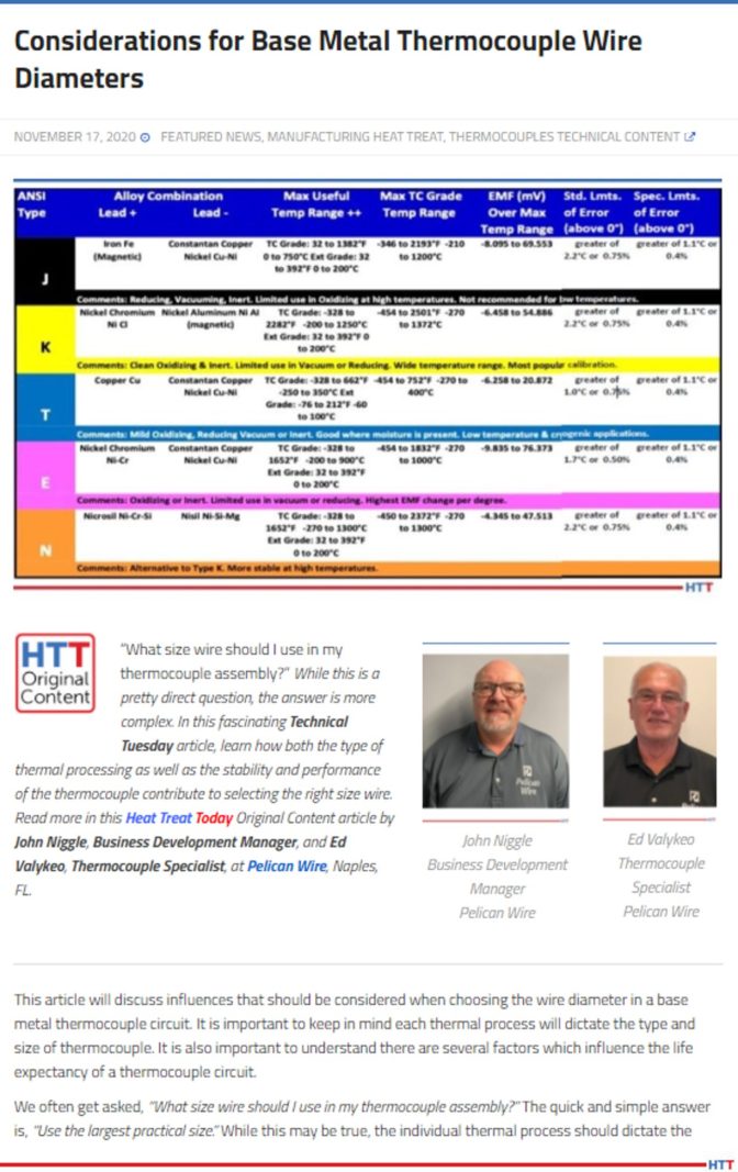
EV: J, E, K, N and T are the most common noble metal thermocouples. Obviously, you've got two dissimilar metals or, what we refer to in thermocouples, two legs of the thermocouple – the positive leg and the negative leg. So, for instance, on a Type J thermocouple, you're using iron as a positive leg, which is basically pure iron, (there are some coatings on the iron to help against oxidation and things like that), and the other leg is a copper nickel alloy. That makes up the two legs of the Type J thermocouple.
If we look at Type K thermocouple, the negative leg is the KN which is, basically, just high nickel with a little bit of chromium; the KP leg, or the positive, of Type K is higher content nickel chromium. There are also some other minor elements.
With Type T, the positive leg is pure copper. The TN leg is, again, a copper nickel alloy. So, when we talk about Type E, what is interesting is that with the Type E thermocouple, you're actually taking the Type KP leg and matching it with the TN leg. So, again, it's just a mismatch or some hodgepodge of some legs.
DG: So, you're using some lingo that I'm just picking up on and I want to make sure our listener's are, as well. You talk about a P and an N leg. Obviously, you didn't say it, but you're talking about a positive leg and a negative leg.
EV: Yes, I'm sorry. KP and KN. So it's K positive and K negative leg.
DG: Great. So, with the Type E, you're taking a few and switching them around and matching them up and seeing what you can come up with.
EV: Yes, that's the E, and I already mentioned the T. N is a relatively newcomer to the thermocouple industry. I say new, but it's still probably 40 or 50 years, I'm not sure when it was developed. But, again, the Type N is similar to the Type K where the KP leg is a nickel and the KN leg is nickel and some silicon. So, it's just a little bit different composition from the Type K thermocouple. But, there are some differences.
Some of the differences, when you're looking at the different types of thermocouples, for example, Type E has the highest EMF output of any of the thermocouples. Your question might be, "Well, why wouldn't we just use Type E because it has the highest output?" What the higher EMF output means is that the sensitivity is a little bit greater in the Type E thermocouple. Then why wouldn't we use that throughout all the industries? Well, the short answer is, a couple things: Type E has a limited temperature range, because, again, you're using that TN leg which is copper nickel alloy and the melting point of a copper nickel alloy is much lower than a nickel chromium alloy. So, that's some of the differences, and with all the thermocouple types, also.
Each one has their own EMF output at certain temperatures but one of the biggest considerations is, really, the environment that you're using the thermocouples in. Type K has good oxidation resistance; Type J, not so much, because you've got a pure iron leg which is going to oxidize much faster. That's some of the differences between the individual thermocouple types.
DG: I assume that if there's oxidation, or any type of corrosion or anything of that sort, it's going to change the EMF, it's going to change the reading and therefore that thermocouple, out the door she goes.
EV: Absolutely. And there have been even some recent changes in some of the specifications that some of the heat treaters are using nowadays where they finally realize that these thermocouples do deteriorate over time and so they start limiting the amount of uses that each thermocouple can be used in, in a bunch of different applications, but heat treating mainly.
DG: Let's pause for just a second and do a little vocabulary. You've mentioned EMF a couple of different times. Could we have just a brief review of that just to make sure? Also, I've heard about millivolts. Are those two things related? If so, how?
EV: EMF stands for electromotive force. It is, basically, when two dissimilar metals are put in contact with each other, a small voltage is generated. When we're talking about millivolts, that's exactly what we're looking at: a millivolt is 1/1000 of a volt. It's a very small amount. If you look at some of the millivolt outputs for some of these thermocouples, at 200 degrees, for example, you're putting out .560 of a millivolt. So, these are small.
DG: And you're saying that it was the Type E that has the highest millivolt of all, so the current that is produced between those dissimilar metals is the highest, but you can't always use that one because in certain temperature ranges you're going to melt one of the legs.
EV: Exactly.
DG: The millivolts are measured by what? I mean, it goes into an instrument that is able to read that? What is that instrument?
EV: Actually, some DVMs (digital volt meters) have the capacity to measure in the millivolt range. So, it could be as simple as a digital voltmeter. But, in the industry, we have temperature controllers, things like that, that you hook a thermocouple up to and it measures the EMF and then it converts it into a temperature.
DG: It will measure that millivolt and then tell us what the temperature is?
EV: Right. With the instrumentation nowadays, it has the formulas in its memory, or whatever, and can convert that millivolt into an actual temperature that you actually read on a meter.
DG: We've got an EMF which is measured in a millivolt. It's going to travel across a long wire, I assume, to some place where it's going to be read. Let's talk about that wire a little bit. The impact of this, whatever EMF is being created, millivolt, what about that wire? Tell me about it and what do we need to be careful of, etc?
EV: We're actually saving that for another podcast, but I will touch on it a little bit. So, there are limitations on the length of the thermocouple. There are a lot of different mindsets, but probably the one I've heard the most is no longer than 100 feet. So, you have your thermocouple sensor and that arrangement, the configuration, can be a number of ways. At PMC Corp. we insulate the wire. You could just take that insulation off at the end, weld the junction there, stick it and [. . .] then run it to a meter.
But in other industries, you may have it in a ceramic tube because of the temperature it's being used at. You have a ceramic tube with a connector at the end, you may run what we consider an extension wire from that point all the way back to your instrumentation. Again, the general rule of thumb, is 100 feet.
DG: Let's talk about that wire with the different types of thermocouples. What do we need to be sensitive to? What do we need to be careful about?
EV: Again, temperature range is probably the first consideration, but then also the environment that it's in. Again, each thermocouple has its limitations on the environment. Some are good in a vacuum, other thermocouples are not good in a vacuum. Some thermocouples are good just in air, (like Type K), but Type J is not so good. It still can be used in air but it will oxidize faster.
Like I said, in an environment of a vacuum, some thermocouple elements will actually leech out or evaporate out and that definitely would cause a problem with the EMF output and would have an erroneous reading. Certain acids you can use some thermocouples in, others you can't.
DG: With all of this pyrometry stuff going around, especially the AMS2750 revision, there are a lot of places where the tightness of the tolerance on the temperature really needs to be paid attention to. Are some thermocouples inherently tighter tolerance, where they can go down to + or –2, or less than that?
[blockquote author="Ed Valykeo, Pelican Wire" style="2"]Special limits of error is the tightest tolerance, and that's according to ASTM. But, there are some customers and some companies that want tighter tolerance material. So, when we talk about that, that's really a special order. Now you have to back all the way back up to the melters that melt these elements and make the thermocouple wire. It's on them to produce something that is a tighter tolerance. [/blockquote]
EV: Again, that was something we were going to touch on a little bit later, maybe on another podcast, because it can be a whole category on its own.
But, yes. If you think about in general, overall, when we're thinking about the different thermocouple types, they basically all have the same tolerances according to ASTM. The rule of thumb, that we kind of use, is from say 200 degrees to 500 degrees, the tolerance on all thermocouples are + or - 2 degrees if you want special limits of air material.
Now, there are other tolerances. In the thermocouple industry, you’ll here – at least calibration-wise – you'll hear special limits of error, standard limits of error and extension grade. Special limits of error is the tightest tolerance, and that's according to ASTM. But, there are some customers and some companies that want tighter tolerance material. So, when we talk about that, that's really a special order. Now you have to back all the way back up to the melters that melt these elements and make the thermocouple wire. It's on them to produce something that is a tighter tolerance. Once that metal is poured in that mold and it's processed down the wire, it is what it is. When they calibrate that wire, you can't really do a lot with it to change the EMF output, per se, other than there are some heat treat operations that can, what they call, stabilize, and there are processes to oxidize thermocouple wire, and things like that, but you're pretty much stuck with EMF right from the melt.
DG: And it's dependent on the material composition or quality of the material.
EV: Absolutely. In some cases, they may melt 10 melts to get 2 special limit of air thermocouple types. I don't think it's quite that bad, bur from my early melting days, we've had to downgrade many a melt because it didn't quite meet the tolerances.
DG: Just reviewing, we talked about the basic history, how they got started. We talked about the difference between noble versus base metal thermocouples. We talked about the different types. We defined EMF, electromotive force. We talked about millivolt a little bit. We talked about the wire, the differences in what we need to pay attention to as far as wire, and some other considerations like temperature range, calibration tolerance and environment.
EV: Just so you know, the only base metal thermocouples there are, at least what ASTM recognizes, are the Type J, E, K, T and N. We covered all the base metal thermocouples.
DG: Just out of curiosity, a noble metal thermocouple, what are those?
EV: There is a fairly large list of those. You've probably heard of thermocouple Type R or Type S thermocouple. Those are all made with noble metal thermocouples. It's not really considered a base metal, but tungsten uranium thermocouples. Those are in more the noble metal category Type C. There is even development of some other additional noble metals: gold is used. Thermocouples are made out of gold.
DG: Those could be expensive. Of course, some of those other metals are more expensive than gold, so, who knows?
Well, that's very interesting. So, J, E, K, N and T are all base metal thermocouples.
I want to make sure that we give appropriate credit to your company. We talked about the fact that you're from Pelican Wire, part of the wire expert group. I want to make sure that our listeners know that they can go check out your website which is pelicanwire.com. You're not obligated to do so, but would you like to give out any other information where they can get a hold of you?
EV: Yes. Through the Pelican website, you can certainly get a hold of me. Our number is on the website. It's 239-597-8555 and it goes through a central board. If anyone wants me, they can just ask for me through the operator.
Doug Glenn
Publisher Heat TreatToday
To find other Heat Treat Radio episodes, go to www.heattreattoday.com/radio and look in the list of Heat Treat Radio episodes listed.
HTA Group (HTA) purchased two vacuum furnaces to augment its support for Australian defense capabilities. The equipment will provide heat treatment processes for HTA’s manufacturing customers in the region to meet defense customer and quality specifications. The project was developed in response to customer demand and market analysis identifying gaps in Australia’s advanced manufacturing industrial framework.
The two new Vector® single chamber high-pressure quench vacuum furnaces from SECO/VACUUM will go to HTA's Melbourne and Sydney commercial heat treatment facilities to provide expanded processing capabilities to support the Australian defense industry.
"HTA is the only Australian Nadcap-approved thermal processor and has had ongoing success with commercial and aerospace operations to date," commented Dr. Karen Stanton, director of Corporate and Strategy at HTA (pictured in the headline image above). "Increasing the footprint of heat treatment assets through the establishment of this capability in Melbourne and Sydney will increase the ability of defense component manufacturers to deliver projects faster and allow them direct access to a qualified local supply chain."
Norm Tucker Director of Operations HTA Group
"SECO/WARWICK Group has the most advanced and user-friendly vacuum furnaces on the market," added Norm Tucker, director of Operations at HTA. "But equally important to me is the way we can collaborate with their team to determine the best furnace features and capabilities to do the job. These two new Vector furnaces will be the first of their capability in Sydney and Melbourne and will be used to heat treat high strength components such as landing gear or brazing engine parts and opening up advanced processing capabilities to our new and current customers."
Piotr Zawistowski Managing Director SECO/VACUUM TECHNOLOGIES, USA Source: secowarwick.com
"HTA has been very smart about how they approach their growth, measuring business opportunities through research and thoughtfulness and looking carefully at the potential upside of their investments," noted Piotr Zawistowski, managing director at SECO/VACUUM. "We are proud to be an integral partner in their planning and execution."
The addition of Vector® vacuum furnaces to HTA’s processing capabilities follows 7 other installations of SECO/WARWICK products in Brisbane and Los Angeles CA, including high-pressure gas quench vacuum furnaces, vacuum aluminum brazing furnaces, and tempering/stress relieving furnaces.
An induction heat treat equipment supplier is offering customized, process-specific training seminars to a leading automotive part manufacturer. With the growing need for training and education among new and less experienced employees, these highly effective training strategies are growing in popularity.
This article shows how one induction heat treat equipment supplier, Inductoheat, has helped Stellantis, a leading automotive manufacturer, improve its in-house heat treat operations and further excel its technology.
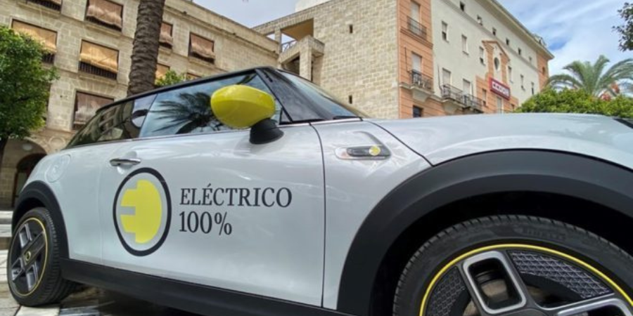
Stringent demands to dramatically minimize transmission noise in hybrid and electric vehicles (EV) as well as in modern internal combustion powered vehicles (ICE) call for innovative technologies allowing to suppress distortion of heat-treated parts, while further enhancing their metallurgical quality and performance characteristics.
Light-weighing initiatives have become essential in vehicle designs. To minimize weight and cost of automotive components, designers might choose to drill holes, reduce cross sections, make intricate transitions, cutouts, re-entrant corners, and custom shapes. In some cases, such attempts result in a component’s geometries that might be prone to cracking during heat treating or might be associated with excessive distortion. Many times, complex geometries of components are linked to intricate hardness patterns and specific requirements for magnitude and distribution of residual stresses.
To be competitive and successfully develop high performance/low distortion components, induction heat treatment users must have a clear understanding of not only principles of electromagnetic induction and associated metallurgical subtleties, but also have awareness of recent theoretical discoveries and technological breakthroughs to further advance part designs.
On multiple recent occasions, Inductoheat has been approached by automotive industry and heat treat suppliers to develop process-specific training seminars as a knowledge-sharing eff ort to give insights on various aspects associated with induction thermal technology. As a response, Inductoheat has developed several practical-oriented training seminars for the automotive industry. These seminars allow present and potential users of induction technologies to understand basic and advanced knowledge associated with electromagnetic induction and to learn novel theoretical achievements, process developments, technological breakthroughs, and practical recommendations.
Another goal in developing these technical seminars is to minimize the negative impact of a generation gap by helping young professionals involved in induction heating to better understand its subtleties and metallurgical intricacies and clarify common misconceptions and confusions existing in different publications.
Best practices and simple solutions for typical induction heating challenges, as well as do and don’t items in designing and fabricating coils are explained. The subject of induction hardening of complex geometry parts (including but not limited to gears, gear-like and shaft-like parts, raceways, camshafts, and other critical components) is also thoroughly discussed, describing inventions and innovations that have occurred in the last three to five years.
Understanding a broad spectrum of interrelated factors associated with various failure modes of heat treat components is an important step in designing new products and developing robust and sustainable processes. Aspects related to failure analysis, part longevity, process monitoring, quality assurance, and robustness of induction systems, novel semiconductor inverter technologies, as well as specifics of implementing Industry 4.0 operating strategy in induction heat treating are also addressed in these seminars. Various design concepts and advanced process recipes/protocols are analyzed to help reduce the energy consumption of induction equipment and enhance cost effectiveness.
Some people traditionally view induction heating as a standalone process or system. Presented materials clearly reveal a necessity to consider induction equipment as part of an integrated system that includes all elements (such as previous process stages and their metallurgical implications, stress analysis, load matching capabilities, and many others) that must be considered to accomplish the process goal.
Finally, Inductoheat conducts these technical video seminars free of charge, addressing specific subjects defined by a particular automotive manufacturer or heat treat supplier.
Technical Seminars for Stellantis
Inductoheat recently conducted two free technical video seminars addressing subjects selected by Stellantis that included aspects related to modern induction thermal processing for traditional ICE vehicle and EV markets.
The first seminar in April was devoted to “Troubleshooting Failures and Prevention in Induction Hardening: General Useful Remedies, Impact of Geometrical Irregularities and Improper Designs.”
In May, the second seminar focused on “Novel Developments and Prospects of Using Induction Heat Treating for Electrical Vehicles (EV).”
Both seminars had the same format: 90 minutes of oral presentations by Inductoheat’s team followed by 20 minutes of Q&A sessions. Attendees included heat treat practitioners, engineers, metallurgists, managers, and scientists involved in induction heating technologies in application to the automotive industry. There were 220 professionals from Stellantis North America registered for the first seminar alone.
Figure 1
Step-by-Step Remedies to Minimize the Probability of Abnormal Outputs
A virtually endless variety of components are routinely induction hardened for different sectors of the industry (Figure 1). Many of these components have their own “personalities” that affect the outcome of heat treatment. Troubleshooting tips and practical remedies to prevent unspecified outputs associated with induction hardening have been developed by industry experts and shared with professionals involved in induction thermal processing. This enhances the knowledge of designers of automotive components and minimizes the probability of cracking and excessive distortion in industrial practice.
Possible abnormal outputs associated with induction hardening include:
Inappropriate microstructures (undesirable phases or their mixtures)
Unacceptable hardness levels (too high or too low)
Inadequate hardness case depths (too deep or too shallow)
Hardness inconsistency/inappropriate hardness pattern (e.g., a deviation of a run-off region)
Excessive grain coarsening, decarburization, oxidation, and scaling
Unfavorable transient stresses/undesirable magnitude and distribution of residual stresses
Crack development and propagation
There is a variety of factors that need to be considered to ensure that abnormal heat treat outputs do not occur. Those factors can be divided into four large groups: 1, 2
Prior microstructure and composition of incoming material
Parts geometry related
Inductor design related
Process protocol related
Inadequate equipment selection or unsuitable heat treat process protocols may be unfit for certain geometrical features of parts or required hardness patterns. It is difficult to overestimate the importance in having a sufficient degree of familiarity with the hardening equipment and process specifics of a particular machine under investigation. Underestimating geometrical irregularities of components (including a presence of holes, keyways, grooves, shoulders, flanges, undercuts, sharp corners, and other geometrical irregularities) by novices as well as a danger of misjudging an impact of different process factors on the outcome of heat treatment have been reviewed in these seminars. Numerous practical case studies and solutions to prevent abnormal outputs have been shared.
Figure 2. Transmission and engine components may contain multiple longitudinal (axial) and/or transverse (radial) holes, as well as angled or cross holes.
Presence of Holes on Selecting Appropriate Inductor Style and Process Protocol
It is not unusual for transmission and engine components to contain multiple longitudinal (axial) and/or transverse (radial) holes, as well as angled or cross holes (Figure 2). Induction practitioners can face certain challenges when dealing with parts containing holes. Distortion of the eddy current flow in the hole area can result in the undesirable combination of “hot” and “cold” spots, excessive shape distortion, and unwanted metallurgical microstructures, which weakens grain structure and substantially increases brittleness and sensitivity to intergranular cracking.
It is important to carefully evaluate the imaginary eddy current flow lines in the vicinity of oil holes. Surprisingly, in many cases, a proper selection of induction hardening technique (for example, single-shot vs. scanning vs. static hardening) in combination with other factors can be essential in helping to dramatically improve heat uniformity and eliminate regions with localized grain boundary liquation that could act as crack-initiation sites.
There are several helpful practical solutions and knowhow shared with heat treaters during these seminars helping to develop robust and failure-free induction hardening processes. For example, appropriate coil copper profiling often allows dramatically reducing or eliminating hot spots in the vicinity of holes. Some of those solutions allow selectively controlling heat source distribution along the oil hole perimeter by providing preferable channels for eddy current flow. Several patented design concepts have been revealed.
It should be recognized that temperature surplus alone might not result in cracking. There are other factors that can contribute to overheating, thereby increasing crack sensitivity. Steel chemical composition is one of those factors. Steels having higher carbon contents are more prone to cracking. Besides carbon content, an unfavorable combination of alloying elements and residual impurities could promote a tendency to crack initiation; the extent depends on the amount and combination of elements present.
For example, sulfur and phosphorus amounts should be minimized to reduce steel brittleness and crack sensitivity. Sulfur reacts with iron, producing hard, brittle iron sulfides (FeS) that concentrate at grain boundaries. FeS also has a relatively low melting temperature, potentially leading to grain boundary liquation and increased sensitivity to heat surplus. FeS in carbon steels is minimized by the addition of manganese to form MnS creating a less brittle microstructure. A high level of phosphorus, copper, and tin can also weaken steel’s grain boundaries causing excessive brittleness and a tendency to crack initiation.
Impact of metallic residual elements can be differentiated based on their presence (e.g., in solid solution), precipitation specifics (for example, a capability to form inclusions such as carbides, sulfides or nitrides), as well as characteristics of formed inclusions (including amount, size, distribution, etc.), and their tendency for segregation.
It is important to keep in mind that transient stresses are primarily responsible for great majority of cracking in induction hardening. Thus, it is essential to have a clear understanding regarding the specifics of their formation. A complex stress state in the vicinity of the oil holes takes place during the heating and quenching cycles. Dynamics of a formation of transient stresses during spray quenching in the locality of the oil hole may have a unique double hump appearance, where the second peak of tensile residual stress might have appreciable greater magnitude compared to the first one resulting in a potential to exceed the strength of the material. This phenomenon must be taken into consideration when developing process protocols.
Additional challenges can appear when the part consists of several closely spaced holes positioned in-line or across from eddy current flow. Case studies have been reviewed and practical suggestions on enhancing microstructures in the vicinity of multiple oil holes were given addressing a double hump of transient stresses. Practical remedies were given to diminish probability of crack initiation when a part consists of multiple, closely positioned oil holes.
Experience shows that in many cases, the proper choice of design parameters (applied frequency, power density, inductor profiling, quench considerations, etc.) allows one to obtain the required hardened pattern around holes free of cracks, even in those cases that may seem first unsuitable for heat treating by induction.
Novel Developments
Newly developed induction thermal technologies occur quite regularly, offering impressive benefits. In its continuing tradition to further excel existing processes, Inductoheat is developing advanced technologies that enhance traditional processes. For example, thanks to newly developed inductor design, one of the world’s largest suppliers of automotive parts has achieved more than a ten-fold increase in a coil life of a single-shot hardening inductor compared to industry average life of conventional single-shot inductors. Enhancement has been verified by the manufacturer’s tool-room tag. Reasoning for such a dramatic coil life enhancement has been explained during seminars. Other benefits of this remarkable technology include a measurable improvement in process robustness and dramatically reduced process sensitivity.
Additional innovations are related to the unique ability of some of Inductoheat’s inverters to independently control power and frequency (like a CNC machine) during the scan hardening or a single-shot hardening, which helps further optimize thermal conditions.
Seminars provided an objective assessment of rapid tempering and stress relieving compared to longer-time oven tempering. An evaluation of mechanical properties and performance characteristics of components produced by different tempering techniques (e.g., longer-time oven tempering vs. induction rapid tempering), impact of steel’s chemical composition (including a carbon content and alloy composition), as well as an impact of hardness case depth and other practical factors when assessing applicability of induction tempering have been reviewed.
It is imperative to be aware that numerous studies recently conducted by various researchers worldwide clearly suggest that under specific conditions, a rapid tempering can be superior to oven tempering in helping to eliminate or dramatically minimize such undesirable phenomena as temper embrittlement (TE) and temper martensite embrittlement (TME) and measurably enhance toughness and ductility of rapid tempered steels.
Conclusion
It is our hope that the materials presented at these technical video seminars will help you to better understand the intricacies of thermal processing using electromagnetic induction and to deliver your company a competitive advantage to become a “world-class” user of this remarkable technology.
References
[1] G. Doyon, V. Rudnev, R. Minnick, T. Boussie, Troubleshooting and Prevention of Cracking in Induction Hardening of Steels, Lessons Learned – Part 1, Thermal Processing, September 2019, p.26-33.
[2] G. Doyon, V. Rudnev, R. Minnick, T. Boussie, Troubleshooting and Prevention of Cracking in Induction Hardening of Steels – Part 2, Thermal Processing, October 2019, p.30-37.
For more information, please contact: Inductoheat, Inc. in Madison Heights, Michigan or visit www.inductoheat.com or www.inductothermgroup.com.
Watervliet Arsenal will receive a new ion nitriding thermal processing furnace system with full controls. It will be fully installed and commissioned in a horizontal configuration.
Ben Bernard Vice President of Marketing Surface Combustion
This is the second ion nitriding furnace supplied from Surface® Combustion, to Watervliet Arsenal; the first was originally over 40 years ago. They awarded a contract to Surface so they could again bring their processing capability in-house. Adding control to the supply chain for product was one of the many reasons they acquired an ion nitriding thermal processing furnace system for their plant. This configuration best suits the facility and Watervliet Arsenal's processing needs, and will also include process development.
Surface has always placed a high value on customer relationships and believes that an equipment purchase is the beginning of something much more than a finite transaction. In fact, they have been working with the Watervliet Arsenal location for over 40 years.
"It is always great to see customers coming back to Surface," said Ben Bernard, vice president of Marketing at Surface, "because they appreciate our incredible product lines as well as our engineering capabilities and long standing relationships."
Sometimes our editors find items that are not exactly “heat treat” but do deal with interesting developments in one of our key markets: aerospace, automotive, medical, energy, or general manufacturing. To celebrate getting to the “fringe” of the weekend, Heat TreatToday presents today’s Heat Treat Fringe FridayBest of the Web article covering Volvo’s fossil-free steel use.
The world’s first “fossil-free” steel delivery, created with green hydrogen instead of coal and coke, will be delivered to the Volvo Group, where it will be used in electric trucks. Sweden’s SSAB Oxelösund made the trial delivery to Volvo in the hopes of building towards a 100% emissions-free manufacturing future.
[blockquote author=”” style=”1″]SSAB’s HYBRIT process uses hydrogen as the reductant as iron ore and limestone are combined to create steel, replacing “coke,” or baked coal. The traditional coal-fired blast furnace is also replaced with an electric arc furnace. The company makes sure the hydrogen electrolyzers, as well as its own arc furnaces, are run on “fossil free” renewable energy as well. What’s more, all of the iron ore used in the process will come from “fossil free” mining operations.[/blockquote]
When you are a new heat treater, there are really only three things you want to know to get your bearings: What is it? How does it work? Why does it matter? That's it. What does that mean when we discuss "VAB"?
This best of the web article walks you through the three questions mentioned above, several advantages of vacuum aluminum brazing, and heating control.
An excerpt:
"The dwell time (soak) at braze temperature must be minimized as melted filler metal is vaporizing in the low pressure (high vacuum) environment. Too much filler metal vaporization can result in poor joint wetting and subsequent loss of joint strength and sealing ability. After the final brazing soak is complete, a vacuum cooling cycle follows, which stops material vaporization and solidifies the filler metal."
An international electric vehicle (EV) automaker has ordered high-pressure gas quenching (HPGQ), tempering, and nitriding furnaces for heat treatment of large high-pressure casting dies, which will be used in the production of aluminum underbody components for electric vehicles.
The tool & die market serving traditional and EV automotive markets use vacuum heat treating technology extensively to produce bright, high-quality parts. SECO/VACUUM Technologies, a SECO/WARWICK Group company, will provide two furnaces and auxiliaries with working zones that can accommodate loads with dimensions up to 1000mm x 1000mm x 2400mm (40″ x 40″ x 96″) and up to 7.5 metric tons of weight.
“[We] have built a reputation with [this client’s] engineering team,” explained Piotr Zawistowski, managing director of SECO/VACUUM, “[and so] we are capable of achieving the required quenching rates within such a large envelope, which will be accomplished with a powerful 500kW quenching system. The [client] also appreciated the custom engineering that we put into handling such a heavy workload.”
The Vector® vacuum hardening furnace is equipped with a convection heating system to improve heat transfer at lower temperatures, thus reducing internal stresses; the cooling system can quench with nitrogen at pressures up to 25 bar. The furnace will exceed NADCA 207 requirements for the quenching process and Class 2 temperature uniformity requirements per AMS2750F.
The nitriding furnace is a pit-type configuration, with working dimensions to match the hardening furnace. The patented ZeroFlow® nitriding process uses uniform high convection heating, precision nitriding potential, and ammonia control, along with vacuum purging to reduce operating costs.


 Mercury Marine of Fond du Lac, Wisconsin, recently launched a plan to upgrade its heat-treating capabilities with a move to the low-pressure carburization and high-pressure gas quench system. The new plan incorporates completely automated vacuum heat treating systems.