Leone

Consider Carbon Footprint in Material Selection Strategy

When carbon-footprint assessment happens during material selection for CAE simulations and product design, the result is more informed and sustainable decisions. Ultimately, Mariagrazia Vottari, chief technical officer at Total Materia AG, shows how informed material choices can identify lower-impact alternatives without compromising structural, mechanical, or physical requirements.

This informative piece was first released in Heat Treat Today’s May 2026 Sustainable Heat Treat Technologies print edition.


Introduction

Governments and industries worldwide are setting increasingly ambitious targets to reduce greenhouse gas (GHG) emissions and strengthen environmental responsibility across supply chains. New sustainability frameworks, mandatory reporting requirements, and carbon-pricing mechanisms are accelerating the shift toward low-carbon production, including stricter expectations for transparent environmental data and lifecycle assessments.

Consequently, global supply chains must adapt quickly, integrating sustainability considerations from the earliest stages of product design through manufacturing, distribution, and end-of-life management. Environmental performance, traceability, and responsible material selection are becoming essential elements of modern engineering and product-development strategies.

Materials themselves represent a major share of global GHG emissions, increasing from 5 to 11 global net anthropogenic GHG emissions (GtCO₂-eq) between 1995 and 2015, and rising from 15% to 23% of global totals. For most products, materials dominate the carbon footprint until manufacturing is complete.

Accurate material selection in early product design and CAE (computer aided engineering) simulations is critical. Beyond traditional factors, such as mechanical performance and cost, engineers must now consider carbon footprint, environmental impact, lightweighting, regulatory compliance, and supply chain optimization to reduce overall emissions.

Therefore, sustainable product design will incorporate Life Cycle Assessment (LCA) of materials using selected indicator(s) providing environmental impact to materials selection. For example, in the automotive industry, ranking (c) is often calculated as c = 0.4 × mass + 0.2 × cost + 0.4 × CF.

Other more complex decision-making models for materials selection have been proposed. This exemplifies the need for reliable and simplified calculation of carbon footprint (CF) value for thousands of diversified structural materials, from carbon and stainless steel to special alloys, nonferrous metals, and polymers, considering their manufacturing routes, processing, finish, and transport. A full LCA study is demanding in terms of both data collection efforts and user expertise requirements, while streamlined LCA often uses generic data related to the materials production, energy used for their processing, and transportation. Typically, streamlined LCA uses only a fraction of the inputs to estimate carbon footprint compared to the full LCA inventory. This article presents recent developments designed to help engineers in the CAE simulation field to cope with these challenges.

Streamlined LCA Methodology

Figure 1. LCIA assessment approach | Image Credit: Total Materia

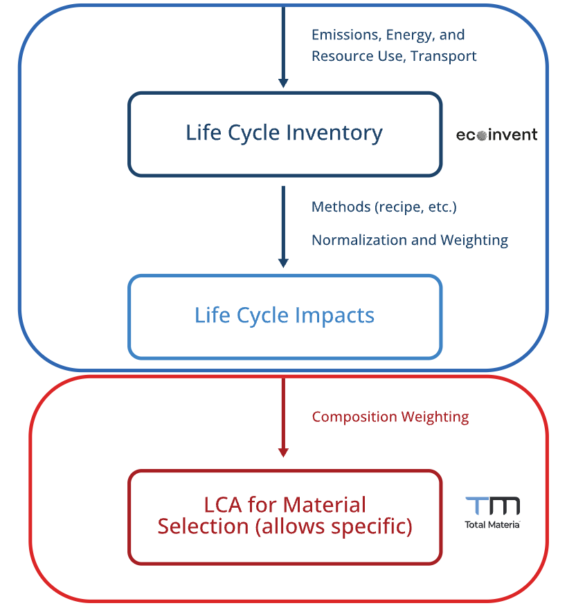
There are numerous simplification approaches in LCA; the following describes the approach that combines the composition of alloys with carbon footprint values of base metal and alloying elements production. The LCA tool described in the current study (Figure 1) can cover a variety of ferrous and non-ferrous alloys due to the use of:

  • Chemical compositions from a large database containing structural material properties, which comprises more than 500,000 materials; and
  • Country, manufacturing route, processing, and transport-specific life cycle inventory (LCI) collected from Ecoinvent v3.10, along with relevant data from scientific articles.

Goal, Scope, Functional Unit and System Boundaries

The aim of this LCA is to quantify the impact of steel and various non-ferrous alloys (Al, Cu, Mg, Ni, and Ti based) according to ISO 14040 standards, analyzing the influence of the composition on the carbon footprint.

The functional unit has been defined as 1 kg of produced material, considering the country of manufacturing and processing as well as transport to the buyer’s gate.

The scope of this study is to estimate the environmental impact of the production and the transport of materials (cradle to gate), accounting for raw materials extraction, manufacturing, and processing.

Inventory Data and Impact Category

Ecoinvent’s Life Cycle Inventory Assessment (LCIA) datasets were used where possible, including:

  • Base metals
  • Alloying elements, utilized in the manufacturing calculation through chemical composition weighting
  • Processing, quantified in kg CO₂-eq per kg of material, per kg of removed material, or per m², varying with the type of processing
  • The energy mix, allowing country-specific calculation
  • Transport, covering a wide range of routes

Calculations are based on the cut-off system model, the IPCC 2021 no LT LCIA method, and the climate change Global Warming Potential (GWP100) indicator.

Additional sources were used from scientific literature for data not available in Ecoinvent. The calculation scope expanded with:

  • Scrap content adjustment manufacturing contributions from various countries/regions
  • Contributions from different manufacturing routes
  • Various processes in different countries/regions

For intensive electricity-consuming processes, such as hot rolling, cold rolling, and stamping, electricity consumption data (measured in MJ/kg or kWh/kg) has been collected. This data, combined with the energy mix information from Ecoinvent, contributes to the final calculation.

Figure 2. System boundaries | Image Credit: Total Materia

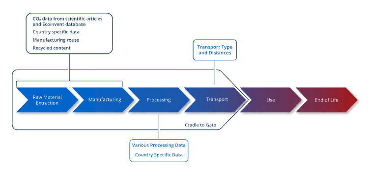
The final CO₂-eq score is the cumulative sum of contributions from material production (manufacturing), processing, and transport as shown in Figure 2, illustrating the system boundaries considered in the study.

Analysis CF Results

In this work, six different alloys that are commonly used have been selected for the carbon footprint analysis. The chemical composition of alloys is defined by specific standard, while details on studied alloys production are presented in Figure 3.

Figure 3. Result of CF calculation for selected alloys | Image Credit: Total Materia

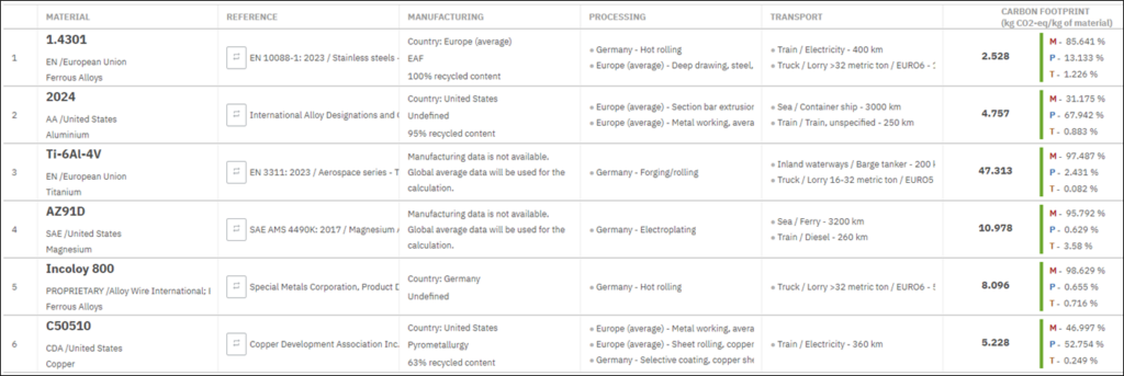
After specifying details on manufacturing (country, method, and recycled content), processing (country and processing applied), and transport (type and distance), the values of carbon footprint are determined for each alloy (Figure 3), providing the contribution of each stage of analysis.

The lowest environmental impact of all studied alloys was steel 1.4301 with a value of 2.5 kg CO₂-eq/kg. This is because a manufacturing route for the 1.4301 alloy was EAF (electric arc furnace) with 100% recycled content, where electricity is used to melt scrap steel and produce new steel, in contrast to BF-BOF (blast furnace-basic oxygen furnace) where extraction of iron ore is needed and relies heavily on coal or coke as a fuel source for the blast furnace, which emits significant amounts of CO₂ during combustion. Although numerous factors or variables play a role in determining the environmental impacts of metal production, one of the most significant parameters is recycled content.

Titanium alloy has the highest environmental impact of all studied alloys, emitting up to 47.3 kg CO₂-eq/kg of material. Ti-6Al-4V alloy was selected for this study even though it is very expensive and has a high energy consumption of production in the long and demanding Kroll process, because it is one of the most popular joint implant materials due to its biocompatibility, low density, and strength.

Although Al, Cu, and Fe-Ni-based alloys have similar CF values (4.7 to 8 kg CO₂-eq/kg), in the case of aluminum and copper alloys, the most significant contribution comes from the processing of those alloys (52 to 68%), unlike Incoloy in which processing contributes a modest 0.72%. The CF value for Incoloy 800 is three times greater than 1.4301 alloy. The high environmental impact of Incoloy 800 is mainly caused by nickel content (max. 10% in 1.4301 alloy, while max. 35% in Incoloy 800) and very high carbon footprint values for nickel itself. This is proof of why chemical composition cannot be neglected.

The effect of transportation is very small, only contributing up to 3.6% for selected transport parameters. However, it can have much higher relative contribution for low-impact alloys, especially over long distances. In Figure 4, the effect of different transport types shows that the selection of air transport can double the carbon footprint value of the material compared to sea transport (for the same manufacturing and processing parameters).

Figure 4. Effect of different transport types | Image Credit: Total Materia
Figure 5. Detailed contribution analysis for 1.4301 steel | Image Credit: Total Materia

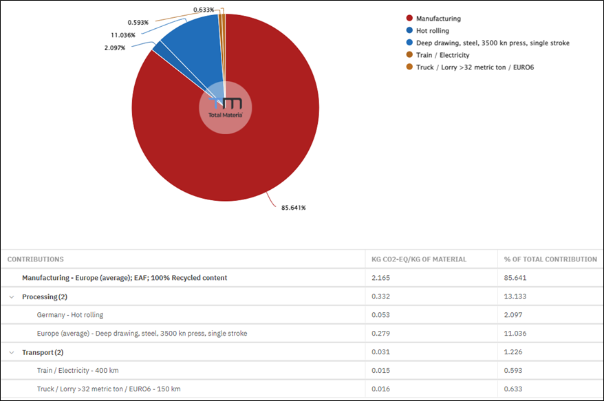
Further contribution analysis can be made for each alloy given the detailed contribution for manufacturing and each processing step, as well as transportation type, as shown in Figure 5 for the 1.4301 steel. Results show that deep drawing increases carbon footprint with a factor of 5 in comparison with hot rolling. This suggests that such processes should be performed on locations having energy supplied from renewable sources.

Material Selection, Looking for a Greener Alternative

Besides identifying more environmentally sustainable manufacturing processes such as alternative production routes, higher scrap content, different locations, processing with lower energy demand, and greener transportation options, another approach to reducing the carbon footprint is to identify alternative materials with different chemical compositions but similar mechanical and physical properties.

Although the selection of alternative materials must consider various factors related to the availability, supply chain, etc., from the environmental point of view, the decision can be facilitated by using a proper cross-reference system that simultaneously suggests alternatives based on various criteria. There are two scenarios for material selection:

  1. In the early design phase when the material is still not selected and when certain mechanical, physical, compliance and sustainability requirements should be fulfilled.
  2. When a certain material already in use should be replaced with a greener alternative but maintain the same characteristics.

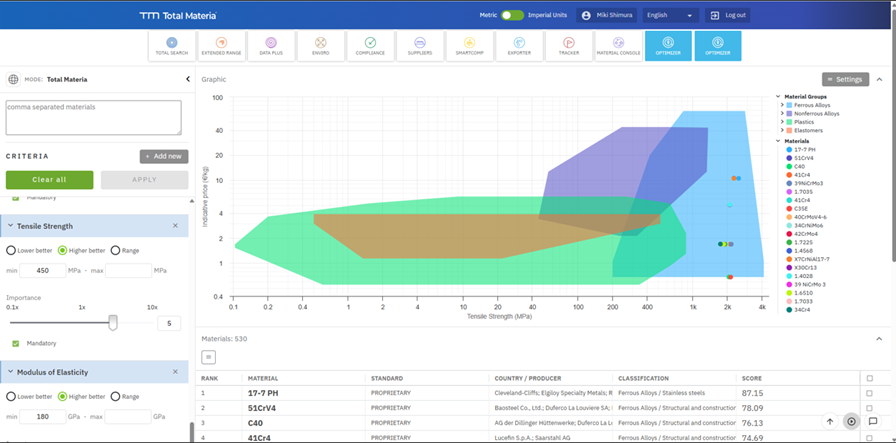
In the first case, material-selection tools like the Total Materia Optimizer can be used to support engineers in comparing and ranking materials based on multiple technical and regulatory criteria. This tool can evaluate thousands of potential candidates simultaneously and filter them according to user-defined parameters, such as mechanical performance, chemical composition, cost, regulatory status, or regional availability as shown in Figure 6.

Figure 6. Results of multicriteria search | Image Credit: Total Materia
Figure 7. Alternatives to 1.4301 steel based on cross references | Image Credit: Total Materia

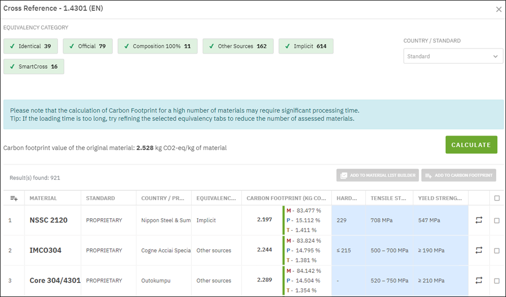
In the second case, when the material is already in use, finding an alternative material with a lower CF value is possible in a material-selection tool’s carbon footprint module through the cross-reference option. The system offers alternatives based on various criteria. As an example for this case, 1.4301 alloy is used with all set-up parameters from Figures 4 and 6 (with CF value of 2.528 kg CO₂-eq/kg). The analysis shown in Figure 7 suggests 921 alternative materials ordered by CF value in ascending order. In this view, a user can add additional columns with mechanical and physical properties to ensure that the material also fulfills the required characteristics. In this example, material NSSC 2120 meets the required mechanical and physical criteria, and the CF value is reduced from 2.5 to 2.2 kg CO₂-eq/kg (which is a reduction of 12%) compared to the initially selected material 1.4301.

Conclusions

This approach for assessing the environmental impact of ferrous and non-ferrous alloys based on material composition and processing routes has been illustrated through a carbon footprint evaluation. It enables engineers to compare materials not only by cost and performance but also by their carbon intensity, supporting more informed and sustainable selection decisions. The method also helps identify greener manufacturing options, such as alternative routes, higher recycled content, lower-energy processing, or reduced-impact transport, early in product design while maintaining quality and performance.

Future improvements include expanding datasets to cover additional processing steps, incorporating more specific manufacturing routes — especially for non-ferrous alloys — and increasing regional coverage to reflect local energy mixes. These enhancements will further refine emission factors and improve the accuracy of carbon-footprint assessments.

References

European Green Deal. 2019. https://eur-lex.europa.eu/legal-content/EN/TXT/?uri=COM:2019:640:FIN (accessed November 2025).

Federal Climate Protection Act. n.d. https://www.bmuv.de/gesetz/bundes-klimaschutzgesetz (accessed November 2025).

Corporate Sustainability Reporting Directive (CSRD). 2022. https://eur-lex.europa.eu/legal-content/EN/TXT/?uri=CELEX:32022L2464 (accessed November 2025).

Carbon Border Adjustment Mechanism (CBAM). 2023. https://eur-lex.europa.eu/legal-content/EN/TXT/?uri=CELEX:32023R0956 (accessed November 2025).

Hertwich, E. G. 2021. “Increased Carbon Footprint of Materials Production Driven by Rise in Investments.” Nature Geoscience 14: 151–155.

Ermolaeva, N. S., M. B. G. Castro, and P. V. Kandachar. 2004. “Materials Selection for an Automotive Structure by Integrating Structural Optimization with Environmental Impact Assessment.” Materials and Design 25: 689–698.

Ic, Y. T., B. M. Hamzaoğlu, and M. Yurdakul. 2024. “A Robust Aluminum Material Selection Process in the Aviation Industry: A Linear Discrete System Stability Test Perspective for Fuzzy Multicriteria Decision-Making.” Arabian Journal for Science and Engineering.

Tasala Gradin, K. 2020. Simplified Life Cycle Assessment Approaches and Potential Impact Shifts. Doctoral thesis, KTH Royal Institute of Technology.

Treloar, G., P. Love, and J. Smith. 1999. “Streamlined Life Cycle Assessment: A Method for Considering Environmental Impact of Road Construction.” In Proceedings of the 15th Annual ARCOM Conference, edited by W. Hughes, 753–762. Liverpool John Moores University. Association of Researchers in Construction Management.

Gómez, P., D. Elduque, J. Sarasa, C. Pina, and C. Javierre. 2016. “Influence of Composition on the Environmental Impact of a Cast Aluminum Alloy.” Materials 9: 412.

Gutiérrez, I. G., D. Elduque, C. Pina, R. Tobajas, and C. Javierre. 2020. “Influence of the Composition on the Environmental Impact of a Casting Magnesium Alloy.” Sustainability 12: 10494.

Gutiérrez, I. G., D. Elduque, C. Pina, R. Tobajas, and C. Javierre. 2021. “Excel Tool to Assess the Environmental Impact of Steels Based on the Composition.” In 9th International Workshop on Simulation for Energy, Sustainable Development & Environment. ISSN 2724-0061.

Total Materia AG. n.d. https://www.totalmateria.com (accessed November 2025).

Wernet, G., C. Bauer, B. Steubing, J. Reinhard, E. Moreno-Ruiz, and B. Weidema. 2016. “The Ecoinvent Database Version 3 (Part I): Overview and Methodology.” The International Journal of Life Cycle Assessment 21 (9): 1218–1230. (Version 3.10, 2023).

International Organization for Standardization (ISO). 2006. Environmental Management—Life Cycle Assessment—Principles and Framework (ISO 14040).

Broadbent, C. 2016. “Steel’s Recyclability: Demonstrating the Benefits of Recycling Steel to Achieve a Circular Economy.” The International Journal of Life Cycle Assessment 21: 1658–1665.

Norgate, T. E., S. Jahanshahi, and W. J. Rankin. 2007. “Assessing the Environmental Impact of Metal Production Processes.” Journal of Cleaner Production 15: 838–848.

Nilsson, A. E., M. M. Aragonés, F. A. Torralvo, V. Dunon, H. Angel, K. Komnitsas, and K. Willquist. 2017. “A Review of the Carbon Footprint of Cu and Zn Production from Primary and Secondary Sources.” Minerals 7: 168.

About The Author:

Mariagrazia Vottari
Chief Technical Officer
Total Materia AG

Mariagrazia Vottari is the chief technical officer at Total Materia AG, leading the Engineering Department and overseeing data content development and material intelligence initiatives. She has a background in mechanical engineering and nearly 20 years of experience in the industry, with a strong focus on materials engineering, data processing, and digital solutions for the manufacturing industry.

For more information: Contact Mariagrazia Vottari at m.vottari@totalmateria.com.

Consider Carbon Footprint in Material Selection Strategy Read More »

Fringe Friday: Global System Chooses Furnace for Fire Tests

We’re celebrating getting to the “fringe” of the weekend with a Heat Treat Fringe Friday installment: Global System, a manufacturer specializing in the production of fire-resistant doors, shutters, and smoke curtains, is adding a furnace from a well-known heat treat solutions manufacturer. The device will be used to carry out fire resistance tests for building products in accordance with the standard temperature curve. Critically, it has the ability to test solutions intended for both industrial and private use, enabling them to significantly increase competitiveness and productivity.

While not exactly heat treat, “Fringe Friday” deals with interesting developments in one of our key markets: aerospace, automotive, medical, energy, or general manufacturing.


The contract covers the delivery of a vertical fire test furnace. This includes a flue gas purification system, a complete set of equipment, installation, commissioning, and staff training.

The furnace, supplied by SECO/WARWICK, enables advanced testing at temperatures reaching up to 1200°C (2192°F), in accordance with current fire resistance standards, which are applicable in both commercial building and maritime construction.

“The device may, in the future, support certification processes which the Partner is considering as their next development step,” says Mariusz Raszewski, Deputy Director of the Aluminum and Atmospheric Solutions Sales Division at SECO/WARWICK. He continues, “Laboratory furnaces for fire resistance testing in various configurations are intended for testing the fire resistance of suspended ceilings, vision panels, walls, columns and other structural elements. These tests are crucial for delivering safe construction solutions to the market.”

“Safety and property protection are priorities in every facility. Global System provides fire protection solutions for various types of buildings — from residential and public utility structures to production halls and warehouses…. The device will allow us to conduct advanced product development research, including analysis of resistance to high temperatures and the impact of various fire conditions. Thanks to this, Global System will be able to further improve its products, increasing their safety and durability,” emphasized Łukasz Jeleński, Technical Director of Global System sp. z o.o.

He continued, “The furnace from SECO/WARWICK will allow us to test the properties of our products, and in the future, to apply for their certification. This is a big step in the company’s development. Additionally, having our own research facilities will enable us to carry out fire tests much faster and shorten the time to market for new solutions.”

The technology of fire testing furnaces is gaining popularity among building material manufacturers, as evidenced by SECO/WARWICK’s supply of a similar device to the French building materials giant KNAUF SAS. Several years ago, the company also supplied ALUPROF with a fire resistance test furnace. The SECO/WARWICK system allows the Partner to test new products, such as windows, doors, and façade systems before they are introduced to the market.

According to the State Fire Service, the highest number of fires in recent years was recorded in 2022 (93,453 incidents), which was an increase of more than 44% compared to 2021 (64,730). In the public utility buildings segment, the number of fires remained around 1,200–1,300 cases per year. Encouragingly, there has been a clear downward trend in fires in residential buildings from 2021 (20,633) to 2024 (16,656). The level for production and warehouse buildings has been relatively stable. In both cases, the number of fires did not exceed 1,500 per year. This shows just how important it is to raise public awareness of the crucial role fire protection systems play in buildings; implementation can contribute to improving safety.

Press release is available in its original form here.

Fringe Friday: Global System Chooses Furnace for Fire Tests Read More »

A Thanksgiving Note

Over the past year, Heat Treat Today has experienced many transitions: sending off several amazing editors into the next, family-focused stage of life and integrating the gifts of several outstanding editors and operations individuals. As we’ve dedicated time to focus on making what we do more compelling and helpful to you, we come to the last month of the year grateful for the opportunities we’ve had to take a call from an industry colleague, receive an editorial email from a reader, and bump shoulders at your heat treat operations and various industry events.

This Thanksgiving, we are thankful for how our team and the industry transforms. This is a particularly acute blessing as we see the final leaves descend this fall. God bless you and keep you and yours through all the changes of life.

For housekeeping purposes: our offices will be closed on November 27 and 28. Happy Thanksgiving!

A Thanksgiving Note Read More »

3 Furnace Upgrades for Environmental Impact

Three aluminum melting furnaces at a Novelis site have been updated to achieve a more than 40% reduction in carbon footprint and significantly lower gas consumption. This project marks an important step forward in the decarbonization of industrial processes.

The upgrade includes Fives’ North American® regenerative technology. The North American TwinBed® II burners, manufactured by the supplier, are recognized for their energy efficiency and low emissions. From engineering and design to commissioning, the project was fully managed by Fives’ North American Combustion’s teams based in Bilbao, Spain.

Emilio Braghi, Executive Vice President and President Novelis Europe Source: Novelis

This joint initiative in Voerde, Germany, by Novelis and Fives highlights the shared commitment to sustainability and innovation. The 40% reduction in carbon footprint is based on gas consumption compared to pre-upgrade levels measured in mid-2023 at the Voerde casthouse.

“Sustainability is at the core of Novelis’ business model,” said Emilio Braghi, executive vice president and president of Novelis Europe. “With our company vision, Novelis 3×30, we’ve set ambitious goals to advance circularity and decarbonization by 2030. The upgrade of our three melting furnaces represents a practical advancement in reducing our environmental footprint and improving operational efficiency.”

“This project represents a new milestone in our long-standing collaboration with Novelis, which began nearly two decades ago,” added Pablo Arribalzaga, managing director for Europe at Fives North American Combustion. “We are proud to support Novelis’ sustainability journey with high-performance, low-emission combustion solutions tailored to their operations.”

Press release is available in its original form here.

3 Furnace Upgrades for Environmental Impact Read More »

Flame and Fire: Fuel Sources and Bedposts

In this Technical Tuesday installment, Jim Roberts of U.S. Ignition entertains readers in a Combustion Corner editorial about how fuel sources became more affordable over time and aspects of combustion burner design. Stick around for his side story on the “innovative” use of bedposts.

This editorial was first released in Heat Treat Today’s October 2025 Ferrous/Nonferrous print edition.


A furnace guy walks into a heat treat facility and sees burners everywhere. Furnace guy says to the faces in the room, “Why did you pick those types of burners?” Thinking this is a trick question, the heat treaters respond, cautiously, “To make things hot?” Of course, they are correct, because making fire and heat is the name of the game, right?

But as we have considered burner styles, designs, flame shapes, and air delivery types with our last couple of Combustion Corner columns, I suspect there was a good deal more analysis given to the selection of burners.

To appreciate the history of burner design, “furnace guy” should realize why burners evolved in the first place: fuel source. When the first burners were starting to be used on box furnaces, they used oil, kerosene, and fuel that had to be pumped. Over the years, many different fuels have been used. Yet, we have a tendency to think of gaseous fuels as the only option for burner performance.

Bedpost Burners

I recall the first time I got called into a facility to try and improve the performance of the furnaces (yep, I truly am a furnace/burner guy). It was a big box furnace that could handle 3-ton quench and temper loads. At that point, I was unaware of the multiple types of burners that were out in the market.

The owner of the shop opened the furnace door for me to see the combustion system. I stared. Sticking into the walls of this big box furnace were bedposts. These “burners” were purchased at 50¢ a post from some hotel auction, and they had about 50 spare posts to boot.

Grinder slots had been cut into the top of these posts. Refractory had been mudded into the mounting blocks to protect the fuel feed, which was being forced, or should I say blown, in through the bed posts and atomized by the pressure of being squeezed through these slots in the knob at the top of the posts!

The fuel? Diesel fuel. Regular, old, out-of-the-pump diesel fuel. Or kerosene, for that matter. I was told the system could also use fire pulverized coal, sucked into the bedpost by pitot feeds of compressed air. They lit the burners with burning oily rags tossed into the chamber and quickly opened the valves controlling the fuel.

I was there to sell new modern high-efficiency gas burners.

I declared that this was antiquated, unsafe, archaic, dirty, and said about a thousand other denigrating comments.

The owner of this heat treat said, “Yep, it’s all those things, and more!” He continued, “It’s also reliable, simple, and predictable.” He mused, “I suppose that that thing hasn’t really broken down or shut off in the 25 years since we built it!”

I’m a fairly quick study and surmised that I was not going to make this sale. Duh! This furnace had everything they needed. And the gas system I was going to propose was going to be expensive.

A Burgeoning Gas Industry and Our Next Column

That furnace was still running when I made a move to another city some 10 or so years later.

Eventually, the gas industry that cropped up made fuel cheap…and I mean cheap. I thought, “I bet that guy and his accursed bedpost burners will talk to me now!” So, I went back, and that fella said, “Yeah, we got out of the business that used that old process and moved on. We’d be glad to talk about modernization.” And we did.

That same outfit that operated bedposts for burners for 50 years became a vanguard for modern efficiency and process improvement.

Natural gas as a fuel source is quite modern. Nowadays, that is essentially the truth: natural gas and sometimes other gaseous equivalents tend to be the most widely used fuels in the industrial world.

When looking at the rapid developments of burner configurations and why they developed, it is best first to understand some of the history of these developments. See you in the next installment to talk about the history of the industrial gas industry.

About The Author:

Jim Roberts
President
US Ignition

Jim Roberts president at U.S. Ignition, began his 45-year career in the burner and heat recovery industry focused on heat treating specifically in 1979. He worked for and helped start up WB Combustion in Hales Corners, Wisconsin. In 1985 he joined Eclipse Engineering in Rockford, IL, specializing in heat treating-related combustion equipment/burners. Inducted into the American Gas Association’s Hall of Flame for service in training gas company field managers, Jim is a former president of MTI and has contributed to countless seminars on fuel reduction and combustion-related practices.

For more information: Contact Jim Roberts at jim@usignition.com.

Flame and Fire: Fuel Sources and Bedposts Read More »

Letter to Heat Treat Today Staff Regarding the Death of Charlie Kirk

               Today is September 11, 2025. It will be, perhaps, one of the most memorable days in your young lives. Seeing as most of you are either in your 30s or younger and have really never experienced a tragic situation such as yesterday’s killing of Charlie Kirk, it will most likely be emblazoned in your minds for life. It is, without a doubt, one of the most horrific and unfortunate, events that you will ever live through. I pray to God that is the case.

               Twenty-four years ago today, I was 39 years old. That morning, I was on an early flight from Pittsburgh to Philadelphia. By the time I got off the plane, rented a car, and was almost to my first sales call of the day at Stokes Vacuum, I stopped at a McDonalds very close to Stokes and learned of the tragic events of 9/11 as everyone in the restaurant was watching the TV in disbelief. It is a memory that literally causes water to well up in my eyes even now, 24 years later, as I write this letter to you. The visceral response has not abated over the last 24 years. A mix of anger and sadness (mostly anger) still stir in my stomach when I think about it. I could easily weep about it, but I’m a man … so I try (unsuccessfully) not to cry.

               Charlie Kirk’s murder, I sense, will be the same seminal event in your young lives. It is a tragic and devastating day.

               As Christians, we don’t let emotions or emotionalism rule our lives. But, let’s remember that Jesus wept. And we, being lovers of Him and followers of Him, can certainly weep in this situation. We can also be angry, confused, and even deeply despairing about our world. We do not, however, dwell in our emotions, we do not sin in our anger, and we don’t remain in a state of confusion, or despair forever. Christ has given us hope and we will return to hope. But first we grieve.

               I know that each of you has a kind and Christlike heart. I know that you have been praying for Mr. Kirk’s family and friends … as we ought to do and as we, thanks to the grace of God, desire to do. I also suspect that tears have been shed on their behalf and will continue to be shed. This is a testament to the grace of God working in you.

               I also know that your Christ-filled hearts are not without hope. Mr. Kirk, because of his faith in the perfectness of Christ, is today with Him. His presence with Christ has nothing to do with how good a man he was — it is solely dependent on what he believed about Jesus (Romans 4:5, But to the one who does not work, but believes in Him who justifies the ungodly, his faith is reckoned as righteousness). Fortunately, Mr. Kirk is in a better place. And for that, we are thankful.

               As we process this tragedy, let’s continue to pray for the Kirk family, for each other, and for those who do not currently share our Faith in Christ — specifically that this event might make us love Christ all the more and make us closer to Him and compel others to trust in His perfectness and love for them.

With much love (and tears),

Doug

Letter to Heat Treat Today Staff Regarding the Death of Charlie Kirk Read More »

Will In-House Heat Treaters 3D Print the “Cutting Edge”?

If you are one of many heat treat professionals watching AM take over the industrial world with bated breath, it may be time to stop watching and start doing. This article highlights the rapid rise of AM and how changes in your heat treat operations may be needed.

This informative piece was first released in Heat Treat Today’s August 2025 Automotive Heat Treating print edition.


For manufacturers who produce customized or complex parts and components for the medical, aerospace, automotive, and other industries, additive manufacturing (AM) with metals has the potential to bring innovation and agility to the process.

However, because AM is a somewhat nascent technology, there are still challenges to address before it is widely accepted throughout the manufacturing industry. Fortunately, as research and development continue, the aerospace and automotive industries are beginning to acknowledge that parts made via AM are robust enough for use in safety-critical applications. Manufacturers who want to use AM to gain a competitive edge are advised to zero-in on the most suitable method for metals and determine in which applications AM presents an economically viable solution.

The Additive Manufacturing Market

AM, also known as 3D printing, is the process of creating an object based on a digital file, such as a computer-aided design (CAD) or one created with a laser scanner. Unlike traditional manufacturing methods that often involve cutting or subtracting material from a solid block (like machining), AM involves building up thin layers of material — usually metal, ceramic, or plastic — one by one using a 3D printer.

AI-generated image of 3D-printed turbine engine components

AM is increasingly transforming the manufacturing industry, enabling faster prototyping, customized production, lightweight parts, and complex shapes and geometries that would be impossible to manufacture using conventional casting, machining, or subtractive techniques, such as milling, grinding, carving or shaping.

For product design, prototyping, and reverse engineering applications, AM allows designers to rapidly print parts as a single piece, reducing material waste, saving time, and reducing costs, all while getting new products to market faster. Although the same advantages apply to traditional manufacturing applications, manufacturers have not been as quick to adopt the technology.

Still, the AM industry is seeing growth. A recent report from Grand View Research states that the global AM market size was valued at over $20 billion in 2023 and is expected to grow at a CAGR of 23.3% from 2023 to 2030, with unit shipments of 3D printers expected to reach 21.5 million units by 2030 thanks to a growing demand for prototyping applications in the healthcare, automotive, aerospace, and defense industries. The report also acknowledges that rigorous R&D in 3D printing will further contribute to growth.

Additive Manufacturing Techniques for Metals

Currently, three primary techniques are used for AM with metals: laser powder bed fusion (LPBF), directed energy deposition (DED), and binder jetting.

LPBF

LPBF technologies, including direct metal laser sintering, selective laser sintering, and direct metal printing, use a laser to sinter or fuse powdered metal particles until a complete part if formed. LPBF processes typically include heating the bed of powdered metal to a consistent temperature. The printer begins applying the first layer over a build plate, fuses the powder particles together with a high-powered laser, and then continues the process layer-by-layer until the part is finished.

After the part is printed using LPBF, it is removed from the powder bed, cut away from the build plate, heat treated to prevent internal stresses, and finally machined or polished to achieve the desired surface finish.

LPBF is limited by the size of the print bed, so it is not suitable for manufacturing large components or parts.

DED

DED using powdered metals also relies on a laser to produce metal parts. However, rather than spreading powder on a bed, the DED machine blows powdered metal out of the print head and uses a laser to fuse the part during construction.

DED-manufactured parts require post-processing heat treatment and machining steps. And while DED is a faster process than LPBF, there are a limited number of materials that can be used in the DED process, and the technique still needs more research and development before it sees widespread commercial use.

Binder Jetting

Binder jetting deposits a layer of loose metal followed by a layer of binder material layer by layer to create the product. During the process, a binder jetting machine distributes metal powder over the print bed to form an unbound layer. A jetting head then spreads a binder to adhere the powder. The machine continues to spread alternate layers of building material and binder to form a complete product. Sintering is generally required after printing to remove the binder, resulting in a part that is composed entirely of metal.

While binder jetting is a fast process and offers the opportunity to create and sinter parts in batches, it is currently a more expensive option. However, research and development into this technology, the availability of binder jets from companies (e.g., Markforged and HP), and the potential to use binder jetting for high-volume batch production may eventually make binder jetting the technology of choice for metal AM.

Post-Processing Heat Treatment for AM Parts

No matter the print technique, some AM-printed metal parts will require post-process heat treatment in which the printed part is subjected to specific temperatures and durations and then cooled to enhance or customize the properties of the metal material and optimize performance and reliability of the part.

Applying controlled heating and cooling cycles during post-printing heat treatment eliminates internal stresses created during the AM process to prevent distortion, cracking, and warping that would negatively impact part performance and reliability. Heat treating can also be used to increase hardness, density, strength, and fatigue resistance to optimize performance of the part. Furthermore, heat treating can be applied to customize the mechanical properties of the final part and provide specific characteristics so that it performs reliably in the intended application.

The type of heat treatment used following AM will depend upon the printing technique, metal material, and desired characteristics and properties. Annealing, sintering, normalizing, quenching, and tempering are commonly used. Hot isostatic pressing (HIP) — another post-process option that is used to reduce porosity and improve the density, performance, and reliability of AM-printed parts — will be specifically addressed in a subsequent article release.

Greater Acceptance in Industry Sectors

Metal alloy 3-D printed components

While AM has been widely used for prototyping and reverse engineering, adoption of the technology has been slower for the manufacture of finished parts and components. Stephen Feldbauer, director of Research and Development, with Abbott Furnace Co., suggests that the right approach to AM with metals depends upon the ability of manufacturers to refine their application. “Manufacturers should not take the ‘shotgun’ approach of ‘I can print anything,’” comments Feldbauer. “Instead, they should focus on what makes the most sense for them and specialize in those parts rather than just printing something because it’s possible.

However, because it provides significant benefits, AM does have application in the several manufacturing sectors. Advantages in using AM to produce parts include minimization of waste, time and cost efficiency, and the ability to customize parts for single-use applications or low-volume production runs.

Thanks to these benefits, AM is currently being used in the following industries:

  • Aerospace: functional parts, such as engine turbine blades and fuel systems 
  • Automotive: various components, such as suspension systems, engine parts, and door panels
  • Defense: obsolete parts, as well as vehicle and weapon components
  • Medical: implants, prosthetics, and other apparatuses

And, as AM technology continues to expand, it is becoming more widely accepted and is most notably being employed to create safety-critical aerospace and automobile parts. For example, General Motors (GM) announced that it is using AM-printed seatbelt pillar adjustable guide loops in its all-electric Cadillac Celestiq, making them GM’s first safety-related AM-printed metal part. 

The component is made by Azoth using Markforged metal binder jetting technology with a liquid binding agent. Following the process, the metal parts are then sintered, polished, and plated. Automotive sector acceptance of additive manufactured safety-critical parts is a tremendous boon for the AM industry.

Experts like Feldbauer see the need for manufacturers to make a few key decisions for this technology to become a reality. “For additive manufacturing to be a commercially viable solution,” he argues, “manufacturers must determine which parts they can 3D print with high levels of success and where printing is cost effective and profitable. Commercial viability is really the determining factor as to whether a part should be 3D printed or made using conventional manufacturing techniques.”

Currently, though, AM seems to be benefiting smaller jobs. According to Feldbauer, AM usually makes the most sense for small runs where there is a need for customized tooling; in these cases, manufacturers run into too complex of shapes or simply to time or cost intensive.

The Future of AM

While AM is increasingly accepted as a beneficial process across many industries, it still faces challenges affecting its usage more broadly, such as material restrictions, bed or plate sizes for techniques that rely on bed printing, and the need to purchase high-end printers from a market that is constantly consolidating. Research and development into the process, more diversity in technologies, increased availability of AM outsourcing companies, and the benefits associated with cost, time, and material reductions are expected to be a driving force in widespread commercial adoption.

Stephen Feldbauer, director of Research and Development with Abbott Furnace Co., updated Heat Treat Today on the state of AM in 2025

As the technology continues to mature, AM will continue to expand into industries where the availability of high-volume AM production, such as is possible with binder jetting, would reduce the cost of part manufacturing. Additionally, optimizing post-process heat treatment methods will help further enhance the cost effectiveness of AM with metals and enable more customized characteristics. These advances could make AM an attractive and economical option for manufacturers, so those who want a competitive edge should begin to focus and refine application of AM to the parts for which it will be most worthwhile.

References

Grand View Research. 2022.  Additive Manufacturing Market Size, Share & Trends Analysis Report by Component, by Printer Type, by Technology, by Software, by Application, by Vertical, by Material, by Region, and Segment Forecasts, 2024 – 2030. April 2022. Grandview Research. Report ID: GVR-4-68039-922-9. https://www.grandviewresearch.com/industry-analysis/additive-manufacturing-market#

Check out our AM/3D Trivia to test your knowledge of the AM/3D industry, the processes, and the technology.

This editorial was written by the Heat Treat Today Editorial Team.


Will In-House Heat Treaters 3D Print the “Cutting Edge”? Read More »

10 News Items To Keep You Current

Heat Treat Today offers News Chatter, a feature highlighting representative moves, transactions, and kudos from around the industry. Enjoy these 10 news items, featuring a multi-million dollar expansion, furnace additions, a 1,000,000 load milestone, and more!


Equipment & Company

1. NUTEC Bickley will deliver a four-car shuttle kiln to a global leader in energy technologies. The gas-fired shuttle kiln will typically operate up to 2012°F (1100°C) and employs a twin-deck kiln car setting. 

2. Century Aluminum will invest $50 million into restarting a South Carolina smelter. 50,000mt of idled production is intended to be revitalized through the restart.

3. HT-MX Heat Treatment has added nitriding to one of their comprehensive Nadcap scope, including carbon steels, stainless steels, nickel alloys, aluminum, lab services, HIPing, and more.

Personnel

4. Quaker Houghton welcomed Dr. Arisbeth Rodwick to the Quaker Houghton team as the senior product application manager (PAM) of Heat Treatment and Forging, effective July 14, 2025.

5. Tom Hart has been promoted to director of sales for North America at SECO/WARWICK, USA. Tom’s promotion comes at a pivotal time, as SECO/WARWICK consolidates its U.S. operations.

6. Kevin Stein Joins Hubbard-Hall as the director of Sales & Business Development. Stein succeeds Jeff Davis, who will retire at the end of October after 42 years with Hubbard-Hall.

Kudos

7. AHT President, Mikel Woods, celebrated his 20th work anniversary this month.

8. ECM USA celebrated a 1,000,000 load milestone with one of their automotive parts manufacturing customers. 20 years ago their ECM FLEX vacuum furnace systems started processing loads 24/7 — recently surpassing 1,000,000 loads.

9. SuperSystems celebrated 30 years as a company.

10. Tenova has been awarded the Front-End Engineering Design (FEED) contract for a Direct Reduced Iron (DRI) pilot plant — a key element of the NeoSmelt project, which aims to develop a groundbreaking low-emission ironmaking facility.


10 News Items To Keep You Current Read More »

NITREX (NTS & UPC) Acquired By Global Furnace Manufacturer Group

Breaking News: The NTS & UPC business divisions of NITREX, a manufacturer of industrial furnaces focused on nitriding solutions, will be acquired by the AICHELIN Group, a global provider of industrial heat treatment solutions. For clients, this means access to a broader range of technologies and stronger local support.

Headquartered in Canada, NITREX has around 250 employees in five countries. The business unit Heat Treating Services is not included in the scope of the acquisition.

The transaction represents the largest acquisition in AICHELIN Group’s history. For employees, the acquisition opens up new perspectives within a strategically focused industrial group. The Group notes in their press release that it “will become the largest global furnace manufacturer in its industry of heat treatment solutions,” with a reach of combined sales at more than EUR 230 million and employing over 1,350 people across 23 locations in 11 countries throughout Europe, Asia, and North America. The Group is also represented by a global network of sales partners.

Christian Grosspointner, CEO of AICHELIN Group.
Christian Grosspointner
CEO
AICHELIN Group.
Source: AICHLELIN Group

The acquisition brings together two highly complementary portfolios: NITREX adds renowned expertise in nitriding furnaces to AICHELIN’s broad technology offering. The geographic fit is equally noteworthy, with NITREX’s operations in the U.S., Canada, Poland, Germany, France, and China integrating seamlessly into AICHELIN’s regional structures.

The acquisition marks an important milestone in the implementation of AICHELIN’s Strategy 2030, which focuses on sustainable growth through regional proximity, diversification, and technological progress.

“This acquisition marks a new chapter for AICHELIN. By combining forces with NITREX, we are unlocking innovation potential and global synergies that will benefit our customers, employees and stakeholders alike,” says Christian Grosspointner, CEO of AICHELIN Group. “We are proud to welcome NITREX into our Group.”

AICHELIN is expanding into new markets and client segments, both through internal innovation and targeted acquisitions. With this acquisition, the Group is thus advancing its goal of becoming a lifecycle partner for heat treatment clients worldwide, supported by digital services and localized operations.

Press release is available in its original form here.


NITREX (NTS & UPC) Acquired By Global Furnace Manufacturer Group Read More »

Truck Beam Heat Treat Line For Auto Industry

A truck beam heat treat line with two large walking-beam furnaces is currently being installed for a leading Latin American auto structural component designer and manufacturer. The industry leader will use one furnace for austenitizing and the other for tempering. The truck beams are 13 in (33 cm) wide, 4.5 in (11.5 cm) high, and 49 ft (15 m) long, weighing at about 625 lb (285 kg). A closely controlled environment is necessary in order to induce the required change to the steel beams’ crystal structure.

The furnace line will be provided by NUTEC Bickley, their third such order for this auto industry manufacturer.

New furnace line from Nutec Bickley
Source: Nutec Bickley

The austenitizing furnace is a continuous unit, capable of treating 60 beams (roughly equivalent to 17 tons of steel) per hour. It has an operating temperature of 1670°F (910°C), and a maximum temperature of 2010°F (1100°C). There are 10 automatic control zones, designed to promote temperature uniformity.

There are 29 high-velocity burners, sited above the load. These allow for low NOx emissions, featuring stable high excess air and excess fuel operation, direct spark ignition, integral air and gas meters, sturdy cast construction and flame rod ionization. The burner configuration creates gas recirculation and allows uniform heating of the load and better heat transfer to the product through radiation mechanisms and convection.

The furnace employs NUTEC Bickley’s IMPS™ combustion system for energy savings, enhanced process control, optimal kinetic energy utilization from burners, temperature uniformity without excess air, a high turndown ratio, and other key benefits.

The tempering furnace — capable of heat treating beams at a rate of 60 pieces per hour — has an operating temperature of 915°F (490°C) and a maximum temperature of 1110°F (600°C). There are six automatic control zones and the heating method for tempering is via air circulation with a vertical flow pattern, ceiling to floor with six centrifugal fans.

Both of these furnaces benefit from insulation based on the patented Jointless® ceramic fiber system that allows fast heating and cooling and reduces heat storage. Using MacroModules, this insulation is 8 in (20 cm) thick in the combustion zones. Thermal efficiency has also been guaranteed with a specifically design of the door frame and canopy for both access and exit doors. Both furnaces are fully NFPA 86 compliant.

The press release is available in its original form here.


Truck Beam Heat Treat Line For Auto Industry Read More »

Skip to content