Solar Atmospheres in Souderton, PA, has commissioned two additional 2-bar vacuum furnaces, expanding its capabilities to meet demand in the aerospace and industrial gas turbine sectors. The equipment will allow the company to specialize in hydride/de-hydride processing of titanium, tantalum and niobium.
Mike Moyer Vice President of Sales Solar Atmospheres Souderton
These vacuum furnaces, produced by the heat treater’s sister company, Solar Manufacturing, feature large working hot zones (45” x 45” x 72”) and are rated for operations up to 2400°F with a precise temperature uniformity of ±10°F.
“We’re thrilled to add these advanced furnaces to Solar Souderton’s lineup,” said Mike Moyer, vice president of sales, at Solar Atmospheres. “Equipped with Solar Manufacturing’s latest control systems, they ensure efficient, safe operation — meeting our customers’ needs for competitive pricing and fast delivery. This installation reinforces our commitment to consistently high-quality service.”
More Solar Atmospheres News…
Robert Hill, FASM President Solar Atmospheres of Western PA
Solar Atmospheres of Michigan, Inc., announced the completion of its 20,000 square-foot facility expansion, marked by the official receipt of an occupancy permit from Chesterfield Township.
“Next week, we’ll begin the process of moving our Shipping and Receiving Department, along with other essential ancillary equipment, into the newly completed adjoining building,” said Bob Hill, president of Solar Atmospheres of Michigan. “This expansion is a vital step forward, enabling us to optimize workflow, boost production capacity, and further improve the quality of our vacuum heat treating services for our valued clients.”
The expanded facility will allow Solar Atmospheres of Michigan to streamline operations and meet growing customer demands from various industries.
The press releases are available in their original forms here and here.
A U.S. military firearms manufacturer announced its plan to update its in-house stress relieving operation with a new vacuum retort furnace. The new equipment will be replacing an outdated vacuum stress relieving furnace in order to keep up with production demands.
Piotr Zawistowski Managing Director SECO/VACUUM Source: SECO/VACUUM
The SECO/VACUUM retort furnace will be used to stress relieve firearms components at 1400°F (760°C). At this relatively low temperature, the process is used to prevent subsequent part distortion while enhancing the quality of the firearms.
“Their old furnace was showing its age,” said Piotr Zawistowski, managing director of SECO/VACUUM, USA. “Once we showed them the control system advancements, the cycle time improvements, and the more competitive lead time we could offer, the upgrade really made sense from both a quality control and production pace standpoint.”
Switching from the vertical configuration of the old furnace to the new horizontally configured furnace will shorten loading times. The turbo-cooling option selected by the firearms manufacturer decreases the cooling cycle from 3.5 hours to 1.5 hours. Improved loading paired with shorter cooling will bring total heat treat cycle times down by as much as 2.5 hours.
The press release is available in its original form here.
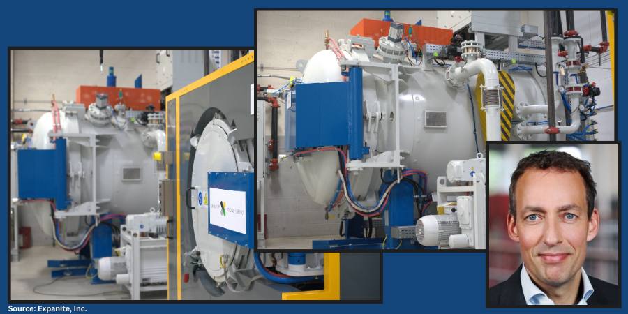
A heat treating company that processes stainless steel, titanium, and other specialty alloys is expanding its operations with a major investment in a larger facility, tripling its heat treatment and surface hardening capacity. The automotive and medical devices industries are among those the company serves at its Twinsburg, Ohio, location.
Thomas Sandholdt CEO Expanite, Inc
With the new equipment, Expanite Inc., a subsidiary of Expanite A/S, based in Denmark, will be able to meet the growing demand for advanced surface hardening and heat treatment solutions. The new furnaces, installed by SECO/WARWICK, have chamber sizes up to 24x24x36 inches and process larger and more complex components. This expansion will allow the company to meet its commitment to sustainability by offering greener alternatives to traditional technologies.
“Our investment is all about meeting the growing demands from our North American customers,” said Thomas Sandholdt, CEO of Expanite. “We’re now able to handle much larger volumes while maintaining the fast lead times and flexibility that our customers expect from Expanite.”
“Our expanded capabilities mean we can now offer our full range of Expanite technologies, including the processes for titanium, right here in the U.S.,” said Claus Løndal, country manager for Expanite North America. “This allows us to serve a wide range of customers while reducing lead times and costs.”
New furnaces installed as part of Expanite’s expansion at its Twinsburg, Ohio, location.
Besides the proprietary Expanite processes, standard vacuum heat treatment processes are offered, including hardening of tool steels (D2, A2, M2, H13, etc.), austenite annealing of stainless (304, 316, etc.), precipitation treatment of PH-steels (17-4PH, 13-8PH, etc.) and specialty treatment of alloys (Inconel 718, MU-metal etc.). The addition of vacuum heat treatment solutions extends the company’s capabilities, offering more solutions, and greater flexibility and ensuring clients receive hardening solutions tailored to their specific needs. In this expansion, Expanite is bringing its patented technology for hardening of titanium to North America.
The Michigan expansion of a furnace manufacturer and heat treating company has advanced with the erection of the entire steel structure in one week. The new 20,000-sq-ft building for Solar Atmospheres of Michigan Inc. will not only house additional vacuum and air furnaces but will also serve as a new shipping and receiving space.
Solar Atmospheres, headquartered in Souderton, PA, relocated equipment to its Michigan facility in April, 2024, where the ten vacuum furnaces are fully operational. The expansion project, which began in July, 2024, will more than double the company’s current footprint in Chesterfield, MI, and is on track for completion by the end of 2024.
The press release is available in its original form here.
Follow the development of this story in the previous Heat TreatToday posts found here, here, and here.
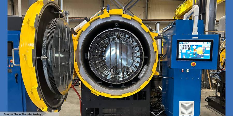
A company developing advanced alternative renewable energy technologies large-scale industrial applications is expanding their heat treat capabilities with two identical vacuum furnaces.
The Research and Development team of Solar Manufacturing, Solar Atmospheres, assisted the client’s engineers to verify the process in the Mentor® Pro vacuum furnace prior to sending this furnace. Solar Manufacturing shipped the identical vacuum furnaces and assisted the company’s engineers to verify the molybdenum shielded hot zone operation of the new equipment at the developer’s facility. The furnace’s internal gas quenching system processes workloads to quench at 2 bar positive pressure in either nitrogen or argon gas, a flexibility that assists the company in achieving results across a wide range of metallurgical applications.
The client also finds benefit from the compact design of the Mentor® Pro features a molybdenum shielded hot zone measuring 18” wide x 18” high x 36” deep, capable of temperatures up to 2500°F, and a workload weight capacity of up to 1,000 lbs.
The press release is available in its original form here.
Ever wish you had a map to follow when navigating your power source? In the following Technical Tuesday article, Brian Turner, sales applications engineer at RoMan Manufacturing, Inc., charts the route that power takes from the source to the load and back again in a vacuum furnace.
This informative piece was first released in Heat Treat Today’s June 2024 Buyers’ Guide print edition.
In a vacuum furnace, the journey from the load (the material being heat treated) to the incoming power involves a complex arrangement of components that deliver, control, and monitor electrical energy. Here’s a breakdown of the path from the source to the load and back to the source of incoming power of a vacuum furnace:
Load
The material — either an item or batch of items — that is undergoing heat treatment; can be metals, ceramics, or composites.
Heating Elements
Common materials for heating elements include graphite, molybdenum, or tungsten, depending on the temperature range and application.
Electrical Feedthrough
These are used to transmit electrical power or signals through the vacuum chamber wall. They often contain insulated conductors and connectors to ensure safe transmission without leaking air into the vacuum environment.
Conductors
The most common methods to connect power from a vacuum power source to the furnace’s feedthrough include air-cooled cables, water-cooled cables, and copper bus bar. Power efficiency can be improved when selecting the length, size, and area between conductors. This can be achieved by close coupling the power system to the electrical feedthroughs, reducing resistance and inductive reactance, and improving the power factor.
Machined Copper Bar Source: RoMan Manufacturing, Inc.
Controlled Power Distribution Systems
The furnace market today generally relies on three primary types of control power distribution systems: VRT, SCR, and IGBT. Each of these technologies employs different methods to regulate the power input to the furnace, which in turn generates the required heat.
VRT (Variable Reactance Transformer)
The VRT controls AC voltage to the load, this is accomplished by a DC power controller that injects DC current into the reactor within the transformer.
The SCR controls the AC output voltage and can be paired with a transformer to step the voltage up or down and close couple to the furnace feedthroughs.
IGBT (Insulated-Gate Bipolar Transistor)
Balanced three-phase voltage is rectified through a bridge circuit to charge a capacitor in the DC bus. The IGBT network switches the DC bus at 1000Hz to control the AC output voltage to a Medium Frequency Direct Current (MFDC) power supply.
MFDC power supply transforms the AC voltage to a practical level and rectifies the secondary voltage (DC) to the heating circuit.
A line reactor on the incoming three-phase line mitigates harmonic content.
Control Systems
These systems manage the furnace’s operation, including driving the setpoint of the power system, temperature control, vacuum levels, and timing. They often consist of programmable logic controllers (PLCs), human-machine interfaces (HMIs), sensors, and other automation components.
Incoming Power
This is the origin of the furnace’s electrical energy, typically from a utility grid. It provides alternating current (AC), which is distributed and transformed within the furnace system to power all necessary components. In industrial settings, power companies usually charge for electricity based on several factors that reflect both the amount of electricity used and how it’s used. Some common charges/penalties are energy consumption (kWh), demand charges (kW), power factor penalties, and time-of-use (TOU) reactive power.
Conclusion
The careful arrangement of heating elements, electrical feedthroughs, conductors, and controlled power distribution systems allows for precise temperature control, ultimately impacting the quality of the processed material. Understanding the role of various control systems, such as VRT, SCR, IGBTs, and transformers is crucial for optimizing furnace performance and managing energy costs
About the Author:
Brian Turner Sales Applications Engineer RoMan Manufacturing, Inc. Source: RoMan Manufacturing, Inc.
Brian K. Turner has been with RoMan Manufacturing, Inc., for more than 12 years. Most of that time has been spent managing the R&D Lab. In recent years, he has taken on the role as applications engineer, working with customers and their applications.
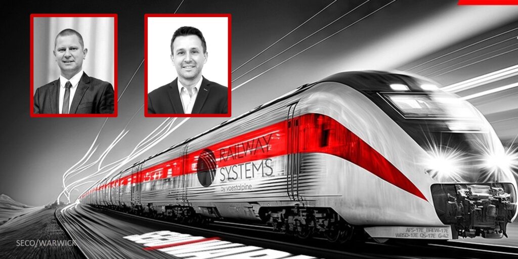
A supplier to the railway industry has ordered a technological line consisting of two vacuum furnaces, three tempering furnaces, and two washers. The line will be utilized for hardening processes of steel parts used in railway rolling stock.
The SECO/WARWICK line for voestalpine Fastening Systems consists of an electric chamber furnace, a washer, a cooling station, and an endothermic atmosphere generator. The hardening process will be carried out in a controlled atmosphere with temperatures up to 1742°F.
Additionally, the technological line includes an electric chamber furnace designed for the heat treatment of steel parts in a protective nitrogen atmosphere at temperatures up to 1292°F, along with a washer, cooling station and endothermic generator. The line will include a loader operating in automatic mode, a set of roller tables and a closed loop water system. The number of the supplied technological line units is selected to ensure the quality of manufactured components.
Mariusz Raszewski, Deputy Director of the Aluminum Process and CAB Furnaces Team, SECO/WARWICK (Source: SECO/WARWICK)
Mariusz Raszewski, deputy director of the Aluminum Process and CAB Furnaces Team at SECO/WARWICK said, “The line is configured in such a way that if the volume of the company products decreases, the customer can also offer commercial processing due to the wide technological spectrum of this main furnace unit.”
The whole solution will be supervised by a master system, which is used for the continuous monitoring of the heat treatment equipment operation and provides advanced data analysis for the production processes.
Mariusz Fogtman, COO, voestalpine Fastening Systems (Source: voestalpine Fastening Systems)
“The universal furnace solution will allow [us] to process details in various configurations,” Mariusz Fogtman, COO of voestalpine Fastening Systems commented. “Apart from technological parameters, it is important for us to limit the processed details’ deformations, which is possible in the ordered solution. SECO/WARWICK presented a partnership and flexible approach to the challenge of this order”
This press release is available in its original form here.
Vacuum furnaces are widely used in the aerospace and automotive industries. These furnaces are used for multiple processes including brazing, aging, and solution heat treating for countless materials. Typically, vacuum furnaces are utilized to ensure a lack of oxidation/contamination during heat treatment. This article will talk about the origins, theory, and main parts of vacuum technology and how it is used in both aerospace and automotive industries.
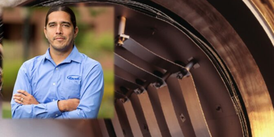
This Technical Tuesday feature was written by Jason Schulze, director of technical services at Conrad Kacsik Instrument Systems, Inc., and was first published in Heat Treat Today's December 2022 print edition.
A Brief History
Vacuum furnaces began to be used in the 1930s for annealing and melting titanium sponge materials. Early vacuum furnaces were hot wall vacuum furnaces, not cold wall vacuum furnaces like we use today. Additionally, most early vacuum furnaces did not utilize diffusion pumps.
Vacuum Heat Treat Theory
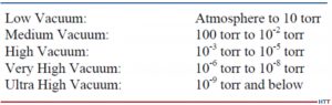
Vacuum technology includes vacuum pumping systems which enable the vessel to be pulled down to different stages through the process. Degrees of vacuum level are expressed opposite of pressure levels: high vacuum means low pressure. In common usage, the levels shown below in Figure 1 correspond to the recommendations of the American Vacuum Society Standards Committee.
Vacuum level will modify vapor pressure in a given material. The vapor pressure of a material is that pressure exerted at a given temperature when a material is in equilibrium with its own vapor. Vapor pressure is a function of both the material and the temperature. Chromium, at 760 torr, has a vapor pressure of ~4,031°F. At 10¯5, the vapor pressure is ~2,201°F. This may cause potential process challenges when processing certain materials in the furnace. As an example, consider a 4-point temperature uniformity survey processed at 1000°F, 1500°F, 1800°F, and 2250°F. This type of TUS will typically take 6-8 hours and, as the furnace heats up through the test temperatures, vacuum readings will most likely increase to a greater vacuum level. If expendable Type K thermocouples are used, there is a fair chance that, at high readings, you may begin to have test thermocouple failure due to vapor pressure.
Figure 1. Vacuum levels corresponding to the recommendations of the American Vacuum Society Standards Committee
Source: Jason Schulze, Conrad Kacsik Instrument Systems, Inc.
Vacuum Furnace Pumping System
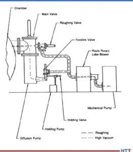
Vacuum heat treating is designed to eliminate contact between the product being heat treated and oxidizing elements. This is achieved through the elimination of an atmosphere as the vacuum pumps engage and pulls a vacuum on the vessel. Vacuum furnaces have several stages to the pumping system that must work in sequence to achieve the desired vacuum level. In this section we will examine those states as well as potential troubleshooting methods to identify when one or more of those stages contributes to failure in the system.
Vacuum furnaces have several stages to the pumping system that must work in sequence to achieve the desired vacuum level. Each pump within the system has the capability to pull different vacuum levels. These pumps work in conjunction with each other (see Figure 2).
Figure 2. Vacuum pumps work in conjunction with one another
Source: Jason Schulze, Conrad Kacsik Instrument Systems, Inc.
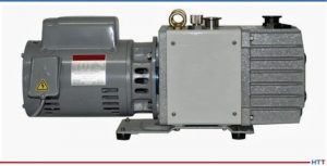
The mechanical pump is the initial stage of vacuum. This pump may pull from 105 to 10. At pressures below 20 torr the efficiency of a mechanical pump begins to decline. This is when the booster pump is initiated.
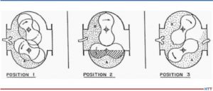
The booster pump has two double-lobe impellers mounted on parallel shafts which rotate in opposite directions (see Figure 3).
Figure 3. Booster pump positions
Source: Jason Schulze, Conrad Kacsik Instrument Systems, Inc.
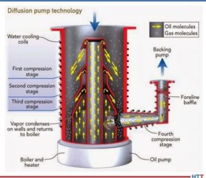
The diffusion pump (Figure 4) is activated into the pumping system between 10 and 1 microns. The diffusion pump allows the system to pump down to high vacuum and lower. The diffusion pump has no moving parts.
Figure 4. Diffusion Pump
Source: Jason Schulze, Conrad Kacsik Instrument Systems, Inc.
The pump works based on the vaporization of the oil, condensation as it falls, and the trapping and extraction of gas molecules through the pumping system.
Image 1. Holding Pump
Source: Jason Schulze, Conrad Kacsik Instrument Systems, Inc.
The holding pump (Image 1) creates greater pressure within the fore-line to ensure that, when the crossover valve between the mechanical and diffusion pump is activated, the oil within the diffusion pump will not escape into the vessel.
Vacuum Furnace Hot Zone Design
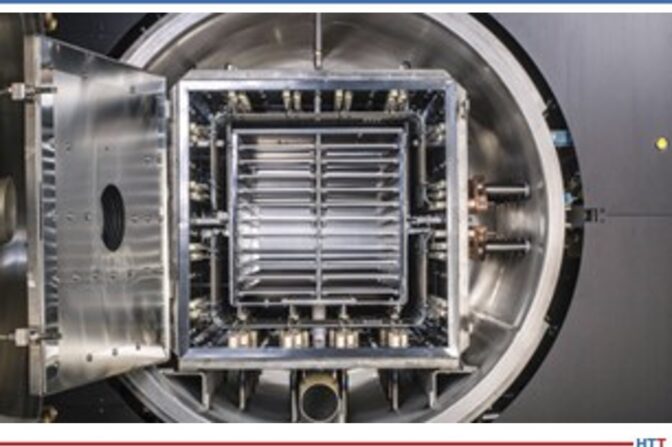
Image 2. Insulated
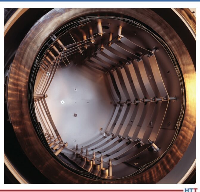
Source: Jason Schulze, Conrad Kacsik Instrument Systems, Inc.Image 3. Radiation
Source: Jason Schulze, Conrad Kacsik Instrument Systems, Inc.
The hot zone within a vacuum furnace is where the heating takes place. The hot zone is simply an insulated chamber that is suspended away from the inner cold wall. Vacuum itself is a good insulator so the space between the cold wall and hot zone ensures the flow of heat from the inside to the outside of the furnace can be reduced. There are two types of vacuum furnace hot zones used: insulated (Image 2) and radiation style (Image 3).
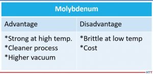
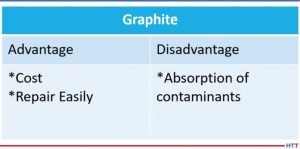
The two most common heat shielding materials are molybdenum and graphite. Both have advantages and disadvantages. Below is a comparison (Tables 1 and 2).
Table 1
Source: Jason Schulze, Conrad Kacsik Instrument Systems, Inc.Table 2
Source: Jason Schulze, Conrad Kacsik Instrument Systems, Inc.
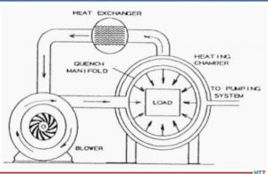
Vacuum Furnace Quenching System
Quenching is defined as the rapid cooling of a metal to obtain desired properties. Different alloys may require different quenching rates to achieve the properties required. Vacuum furnaces use inert gas to quench when quenching is required. As the gas passes over the load, it absorbs the heat which then exits the chamber and travels through quenching piping which cools the gas. The cooled gas is then drawn back into the chamber to repeat the process (see Figure 5).
Figure 5.Diagram of gas quenching
Source: Jason Schulze, Conrad Kacsik Instrument Systems, Inc.
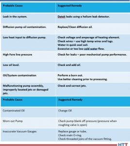
Vacuum Furnace Trouble Shooting
In Table 3 are some helpful suggestions with regard to problems processors may have.
Table 3
Source: Jason Schulze, Conrad Kacsik Instrument Systems, Inc.
Summary
Vacuum furnaces are an essential piece of equipment when materials need to be kept free of contamination. However, there are times when this equipment may not be necessary, and is therefore considered cost prohibitive, although this is something each processor must research. This article is meant to merely touch on vacuum technology and its uses. For additional and more in-depth information regarding vacuum furnaces, I recommend a technical book called Steel Heat Treatment, edited by George E. Totten.
About the Author: Jason Schulze is the director of technical services at Conrad Kacsik Instrument Systems, Inc. As a metallurgical engineer with over 20 years in aerospace, he assists potential and existing Nadcap suppliers in conformance as well as metallurgical consulting. He is contracted by eQuaLearn to teach multiple PRI courses, including pyrometry, RCCA, and Checklists Review for heat treat.
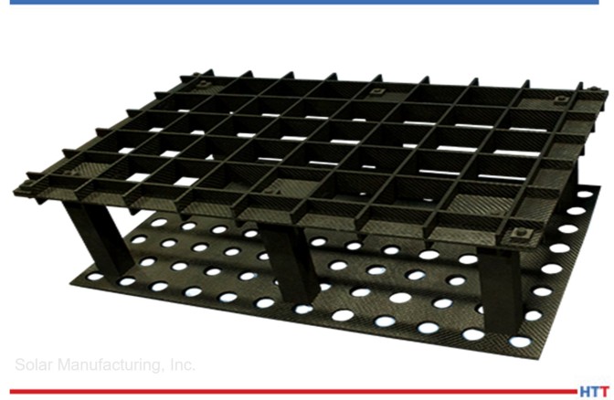
Carbon/carbon composite. What is it? Why is the vacuum furnace industry excited about its use in graphite vacuum furnace fixtures, grids, and leveling components?
In this Technical Tuesday, originally published in Heat Treat Today’s November 2021 Vacuum Furnaceprint edition, explore this new material game changer and learn about its versatility in this informative article by Real J. Fradette, senior technical consultant, Solar Atmospheres, Inc., and Roger A. Jones, FASM, CEO emeritus, Solar Atmospheres, Inc.
Roger Jones, FASM, CEO Emeritus, Solar Atmospheres, Inc. Additionally, Real J. Fradette, Senior Technical Consultant at Solar Atmospheres, Inc.
Introduction
The vacuum furnace industry has searched for many years for the ideal material to be used in fixtures and grids for processing workloads at elevated temperatures. The support structures should be lightweight to achieve desired metallurgical results during the cooling phase of the process cycle. These lighter-weight supporting members will also result in overall lower processing costs due to shorter heating and cooling portions of the overall furnace cycle.
The latest and most successful material used in graphite vacuum furnace fixtures, grids, and leveling components is a carbon/carbon composite (C/C) structure. Graphite is an allotrope and a stable form of carbon.
Carbon/Carbon Composite Material
Carbon fiber reinforced carbon matrix composites (C/C composites) have become one of the most advanced and promising engineering materials in use today. These C/C composites consist of two primary components: carbon fibers and a carbon matrix (or binder). They are among the strongest and lightest high temperature engineered materials in the world compared to other materials such as basic graphite, ceramics, metal, or plastic. C/C composites are lightweight, strong, and can withstand temperatures of over 3632°F (2000°C) without any loss in performance.
Ingots processed with graphite support members
Typical Carbon/Carbon Composite Two-Tier Fixture
Properties of Carbon/Carbon Composites
C/C composites are a two-phase composite material where both the matrix and reinforced fiber are carbon. C/C composites can be tailored to provide a wide variety of products by controlling the choice of fiber type, fiber presentation, and the matrix carbon/carbon composite. They are primarily used for extreme high temperature and friction applications.
C/C composites combine the desirable properties of the two-constituent carbon materials. The carbon matrix (heat resistance, chemical resistance, low-thermal expansion coefficient, high-thermal conductivity, low-electric resistance, low-specific gravity) and the carbon fiber (high-strength, high elastic modulus) are molded together to form a better combined material. The reinforcing fiber is typically either a continuous (long-fiber) or discontinuous (short-fiber) carbon fiber type.
CFC design fixturing for medical implants
Summarizing Properties of Carbon/Carbon Composites
Excellent thermal shock resistance
Low coefficient of thermal expansion
Excellent thermal shock resistance
High modulus of elasticity
High thermal conductivity
Low density (about 114 lb/ft³)
High strength
Low coefficient of friction (in the fiber direction)
Excellent heat resistance in nonoxidizing atmosphere. C/C composites retain their mechanical properties up to 4982°F (2750°C)
High abrasion resistance
High electrical conductivity
Non-brittle failure
Benefits of C/C composites
The carbon fiber matrix can be used to create racks, plates, grids, and fixtures for vacuum heat treating applications.
Various Configurations of C/C Used as Fixtures and Grids
Below are several examples showing different applications of how C/C component graphite materials are used in typical vacuum furnace applications:
347 screens: 347 screens that were annealed at 1875°F in partial pressure nitrogen. The screens were too wide for our normal furnace grid, so we used graphite fixturing to get the screens into the center of the furnace to accommodate the width. The graphite also allows for the screens to settle flat during the heat treating.
Titanium aerospace components: Very intricate and precise graphite fixturing designed to minimize warpage during the solution age heat treatment of these 5-5-5-3 titanium aerospace components. The fixturing was manufactured by 5-axis machining equipment and it allows the part to move during the heat treatment and then settle back into the exact contour of the fixture.
Steel aerospace components: 4340M aerospace components hardened and tempered in partial pressure nitrogen. Graphite fixturing was used to minimize distortion and holes were machined into the graphite plates to help with the cooling phase of the cycle.
Titanium ingots: 10-2-3 titanium ingots homogenized at 2350°F for 24 hours in high vacuum, 10-5 Torr. Each ingot weighs about 10,000 pounds. The fixturing serves two purposes: it keep the ingots from rolling during the heat treatment process, and it also contours to the shape of the ingot so there are no flat spots after the homogenization.
Titanium strips: Titanium strips annealed at 1450°F and aged in high vacuum, 10-5 Torr. Strips were placed on a laser leveled graphite plate to maintain flatness during the run.
Ingot fixtures: These are graphite support members that are used to process the ingots on the first page of the article. They maintain the shape of the ingots while providing support.
The above images are just a small sample of the many supporting graphite designs that have become so critical in vacuum furnace processing. C/C component graphite material can be readily machined for special shapes and applications. We look forward to finding many more ways to successfully use these graphite components.
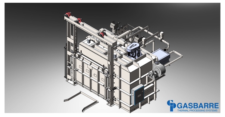
A manufacturer in the aerospace market with captive heat treating capabilities received a custom built atmosphere tempering furnace. With a working load size of 84” wide, 42” deep, and 60” tall, coupled with a max load weight of 6,000 pounds, the furnace is specifically designed for the customers' key manufactured components.
The electrically heated furnace, shipped by Gasbarre Thermal Processing Systems, has an operating temperature range of 350℉ to 1600℉, and passes uniformity at +/- 10℉ per AMS2750E. The system is equipped with custom controls, including Eurotherm brand temperature controlling instrumentation and an Allen-Bradley PLC and HMI.
Automatic atmosphere control is included for running under nitrogen, argon, and/or a hydrogen blend. Custom designed atmosphere cooling systems are installed to reduce overall cycle time. The equipment configuration also enabled the customer to switch from pit furnace style processing, which eliminated infrastructure costs and maintenance concerns.