Vacuum Furnaces

Heat Treat Tips: Vacuum Furnaces: Troubleshooting & Improving Operations

One of the great benefits of a community of heat treaters is the opportunity to challenge old habits and look at new ways of doing things. Heat Treat Today’s 101 Heat Treat Tips is another opportunity to learn the tips, tricks, and hacks shared by some of the industry’s foremost experts.

For Heat Treat Today’s latest round of 101 Heat Treat Tipsclick here for the digital edition of the 2019 Heat Treat Today fall issue (also featuring the popular 40 Under 40).

Today’s tips come to us from Solar Manufacturing Inc., covering Vacuum Furnaces. This includes advice about avoiding disasters, improving vacuum furnace operations, how and when to use water, and troubleshooting.

If you have a heat treat-related tip that would benefit your industry colleagues, you can submit your tip(s) to anastasia@heattreattoday.com  or editor@heattreattoday.com.


Heat Treat Tip #82

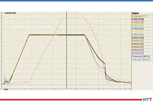
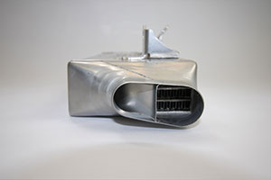
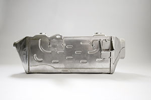
Vacuum Furnace Disaster with High Temperature (2400F) Bake Out

Thoroughly understand the metallurgical definition of “Eutectic Reactions”. Never high temperature bake-out a vacuum furnace with the grids in it, i.e. 2400°F.


Heat Treat Tip #83

4 Tips to Improve Your Vacuum Furnace Operations

Four Suggestions for Improved Vacuum Furnace Operations

Vacuum furnace door o-ring

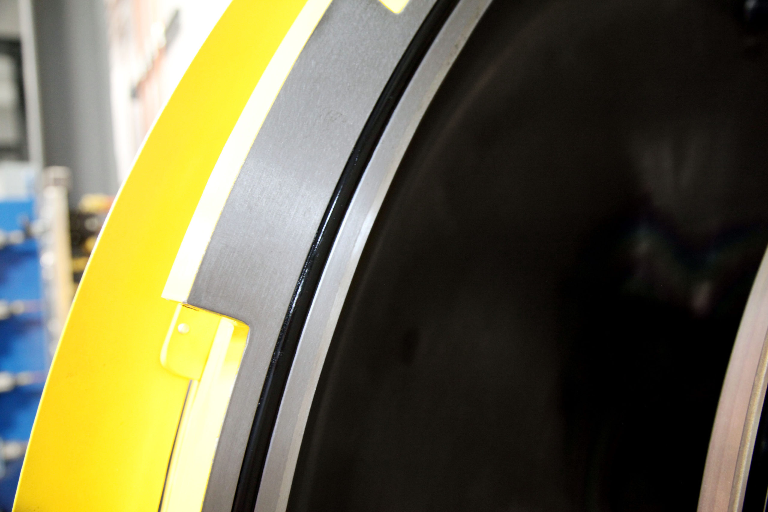
1. When wiping the main door O-ring and flange (which must be done every time BEFORE closing the door, especially after unloading a furnace), wipe with only your bare fingers. You risk a splinter or dirty fingers (so what, you are a heat treater), however, a bare fingertip will detect even minute scratches, nicks, or debris on an O-ring or flange. Wiping with a rag increases the likelihood that you won’t detect those conditions until it is too late. Using your bare fingers is also effective in detecting an O-ring that has become dry and in need of a new application of grease.

Thermocouples inserted into an all-metal hot zone

2. After installing a new control or overtemperature thermocouple, and especially when using a Buna N-type grommeted feedthrough, tighten the feedthrough nut quite snugly, and then retighten it after the initial pump-down, checking it again after several furnace cycles. Much of the time the grommet becomes compressed and pulled deeper into the assembly, leaving the nut loose. If this occurs, the TC could be sucked deep into the furnace during a cycle, possibly breaking when unloading the workload. Further, even a modest movement of the control thermocouple can affect the TUS results and lead to product impact concerns.

Vacuum furnace with front door bolted

3. If using an older vacuum furnace with a bolted main flange, always make sure to bolt the flange after achieving a vacuum of about -25″HG. If the door is bolted prior to sufficient evacuation, the bolts will become loose as the O-ring compresses during the pump-down portion of the process. Loose bolts could lead to a gas leak during a positive pressure quench or a vacuum leak during operation.

Recorded chart, green “pen,” of vacuum pump down record

4. During the initial evacuation of a process in a vacuum furnace, let the furnace pump until it gets to a slowly dropping rate prior to introducing partial pressure or turning on the heat. Water vapor is difficult to liberate and it can take some time, especially in a humid environment. Getting as much out as is practical prior to starting a furnace cycle is good practice in the war against discoloration.


Heat Treat Tip #84

When Water Is Your Nemesis!

Typical Stokes 412 vacuum pump oil sight glass

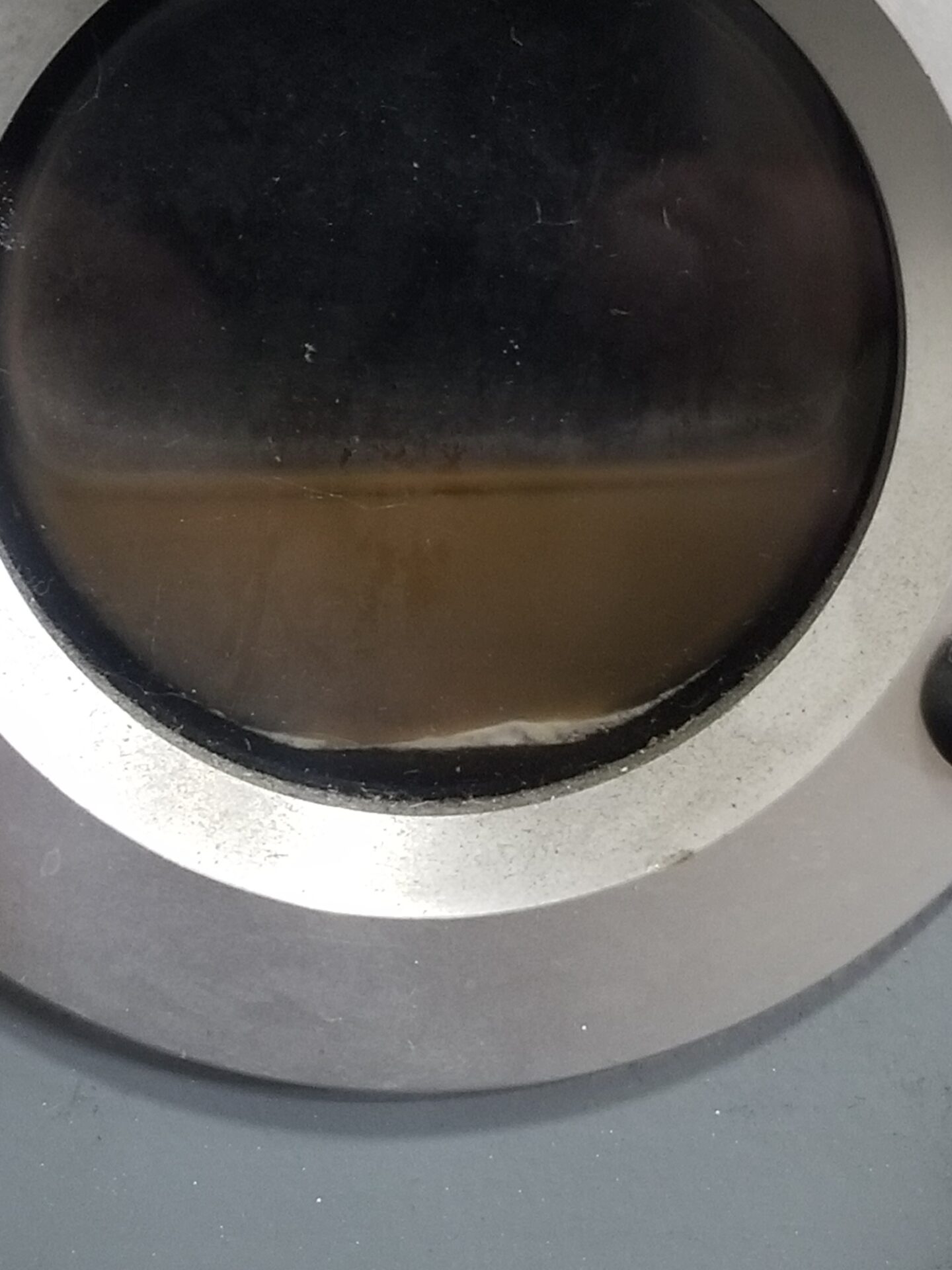
On hot, humid days, moisture collects in the roughing pumps after initial cycle pump down.
• Drain as much water out as possible through the oil drain port of the vacuum pumps, usually about ½ cup of water.
• Crack open slightly, just enough for the water to drain. By cracking the gas ballast valves, this will raise the temperature of the pump and boil the rest of the water vapor off and out through the exhaust piping.
• One thing to remember with the gas ballasts open, the pumping time will be longer. So, don’t forget to close the valves after about 15 minutes.
As soon as the water is removed, only oil will remain.


Heat Treat Tip #85

Typical vacuum chamber water quality sight meters

Cooling Water Type and Chamber Life

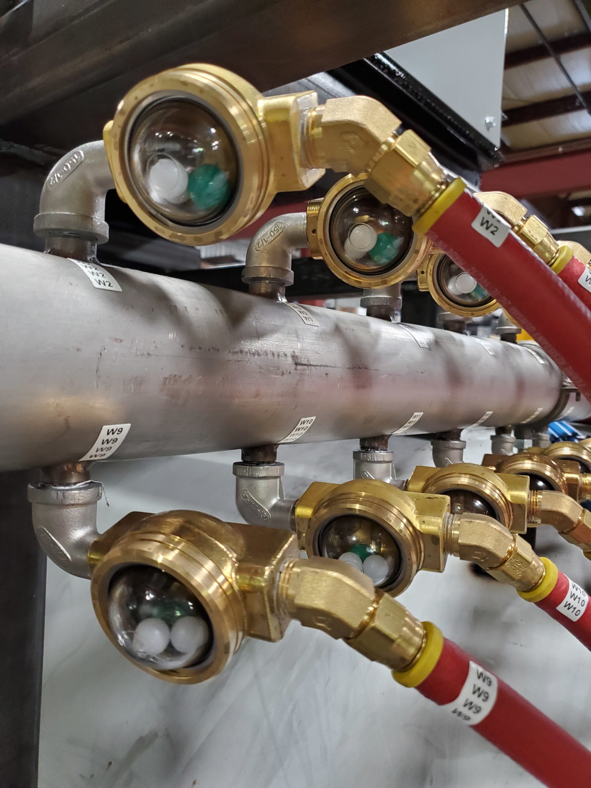
In the vacuum furnace world, the life of the vacuum chamber is very important. Specific care should be taken if the furnace is cooled from a domestic water supply, evaporator cooling tower, or pond water, as these sources are very rich in air and will “rust out” the chamber in less than five years. Therefore cooling water should be provided preferably from a (closed loop) air to water heat exchanger, and the cooling water quality checked monthly to the following chemistry: Water circuit flow indicators should be included to check for water turbidity, low to no particulate, in the cooling water with a site indicator type here noted.


Heat Treat Tip #86

Troubleshooting Furnace Pump Down

Jessi Tatum, furnace operator at Solar Atmospheres, Inc.

If you’re having problems obtaining a vacuum level below the 500 to 50 micron range after furnace pump down, some simple analytics will help pinpoint the potential cause. Ask yourself a few questions: If it is a humid day, how long did the furnace sit open during loading, what is the size of the load in the furnace, and were the parts oily that went in? Any “yes” answers could explain slow pump down. If you rule these out, stop the cycle and watch the coarse vacuum display of the gauge. Does it immediately start going back up by tens or hundreds of microns in a very short time? If it does, you have a large leak. Did the thermocouples get in an area where the door O-ring seals? Has the door O-ring been compromised since the last load? Has some valve been left open slightly? Are any of the gas backfill valves leaking? Was something left in the furnace that shouldn’t be there? If the furnace doesn’t leak back very quickly when you stop the furnace cycle, a contaminated vacuum gauge tube or a poorly performing pumping system could be the cause. Is the booster pump running? Are the diffusion pump heaters on and pulling proper current? By following this simple regimen, you can quickly determine what resources you’ll need to assemble to further troubleshoot the problem and get that load going.


Heat Treat Tips: Vacuum Furnaces: Troubleshooting & Improving Operations Read More »

Diffusion Bonding in Vacuum Furnaces: A Critical Aerospace Application:

Vacuum heat-treating furnaces are used in a wide range of applications, one of the most critical being the heat treatment of components for aerospace applications. These applications typically allow for metals to be heated to extremely high temperatures with little or no gas contamination. One vacuum furnace application is diffusion bonding. This article, which originally appeared in Heat Treat Today’s March 2019 Aerospace print edition, provides a basic explanation of diffusion bonding of an aerospace part carried out in vacuum furnace.


Diffusion bonding is a solid-state joining process. Parts are bonded or welded together without the use of a bonding filler material between the metals. Instead, the bonding process is based on the atomic diffusion of elements between the metals where the materials meet. It is a very effective process for creating a strong bond between dissimilar materials. The process has been used extensively in the aerospace industry for joining materials and shapes to create components or shapes that could otherwise not be made joined to geometric complexity, e.g., multiple-finned channels and honeycomb structures. Today, many diffusion bonding operations are performed in vacuum furnaces.

The diffusion bonding process relies on four process parameters:

  • ultra-low vacuum levels
  • temperature
  • pressure, and
  • time.

All four of these parameters are critical for the successful exchange of atoms between metal surfaces.

Typical Materials Used in Diffusion Bonding

Some metals are more successfully diffusion bonded than others. In the aerospace industry, titanium (Ti) is excellent and widely used. This is due, in large part, to its high specific strength, good erosion resistance, and favorable high-temperature properties. Titanium is 30% stronger than steel yet 40% lighter, and while it is 60% heavier than aluminum (Al), it is twice as strong. Moreover, titanium can be alloyed with other elements such as aluminum, manganese (Mn), iron (Fe), molybdenum (Mo), and other elements to further enhance its considerable strength, particularly at high temperatures. This high-temperature strength is especially useful in the aerospace industry for the containment of combusting rocket engine fuels. Titanium is also valued for its anti-corrosion properties.

In the aerospace industry, titanium is used in manufacturing the structural components of wings as well as skins for hydraulics systems in aircraft, various components of aircraft engines and the cabins of spacecraft, where its qualities are irreplaceable.

Keys to Successful Diffusion Bonding

As mentioned above, diffusion bonding most frequently takes place in a vacuum furnace and is heavily dependent on time, temperature, vacuum levels, and pressure. Let’s take a look at a couple of these parameters as they relate to the vacuum furnace.

Vacuum:

For a successful diffusion bonding process, an ultra-high vacuum level is important. In order for the successful diffusion of atoms to take place between the mating surfaces of the two materials, the surfaces must be microscopically clean. Ultra-high vacuum levels help to prepare the surfaces for a successful bond. The removal of hydrogen is critically important. Any trace of hydrogen could thwart a successful bond. Ultra-high vacuum levels help ensure the elimination of hydrogen from the work area. Also critical is the removal of nitrogen, which, if not eliminated can form nitrides which also can prevent a successful bond. Ultra-high vacuum levels also help remove other trace gases and vapors including oxygen and water, all of which are detrimental to a successful diffusion bond.

Temperature:

Once the desired ultra-high vacuum levels have been achieved – one indication that the surfaces are cleaned and ready for the bonding process to continue – heat is applied to the furnace. The exact temperature of the diffusion bonding process is dependent on the materials being bonded.

Pressure:

Once heat has begun to be applied to the load, argon is typically added to the chamber. Argon, a heavy, inert gas, is typically used in diffusion bonding processes as opposed to nitrogen, because, as stated above, there is a risk of nitride formations if nitrogen is used. Argon avoids this risk. As argon is introduced into the work chamber, and as heat is being applied, the pressure inside the furnace begins to build to the desired level. The exact pressure is dependent on the materials being bonded and other parameters. It is important to note that argon is added during the heat up cycle and not before or after. This is not done before the heat cycle because the expanding of argon might cause an over-pressure situation resulting in the wasting of argon when the pressure is released. Argon is not introduced into a fully heated furnace because the introduction of cold gases into the furnace would cause thermal cycling (temperature drops) as well as thermal shock to internal furnace parts. A controlled introduction of argon into the furnace is a critical part of the diffusion bonding process.

.
Time:

The final parameter is time. Again, depending on the materials being bonded, the diffusion bonding cycle time can vary significantly.

Diffusion Bonding of Turbine Blades

Diffusion bonding is often used to produce turbine blades by bonding the two lateral elements of the blade with another titanium shape in the middle. The uncovered surfaces of the internal shape are covered with a layer of ceramic dust. Once the diffusion bonding treatment has been completed, the parts are subjected to super-plastic forming (SPF) where pressure is used to blow out the sides and raise the edges of the intermediary metal. The part is then given the twist typical of an airfoil blade through hot pressing in a die.

Lighter Parts & Increased Fuel Efficiency

Aerospace companies that use blades produced with this method have found a significant improvement in engine performance. Hollow core fan blades produced with SPF/DB processes are lighter and stronger than traditional fan blades. The result is a 5% reduction in fuel consumption. And reduced fuel consumption is something that makes everybody happy.

About the Author: Guido Locatelli is the TAV VACUUM FURNACES SPA Deputy General Manager and Furnacare, Inc. President, an expert in mechanics, materials, and new technologies in the field of vacuum furnaces. Since 1984, TAV VACUUM FURNACES has been producing customized industrial vacuum furnaces worldwide. In 2015, TAV established its American company group Furnacare, Inc., in Spartanburg, South Carolina. This article originally appeared in Heat Treat Today’s March 2019 Aerospace print edition and is published here with the author’s permission.

Diffusion Bonding in Vacuum Furnaces: A Critical Aerospace Application: Read More »

10 Heat Treat Tips: Vacuum Furnaces

Heat Treat 2019 is coming, and one of the great benefits of gathering with a community of heat treaters is the opportunity to challenge old habits and look at new ways of doing things. Heat Treat Today’s 101 Heat Treat Tips is another opportunity to learn the tips, tricks, and hacks shared by some of the industry’s foremost experts. The inaugural list of 101 Heat Treat Tips was published in the FNA 2018 Special Print EditionThis special edition is available in a digital format here.

Today's Technical Tuesday features 10 Tips -- all from the Vacuum Furnaces category and all supplied by the same equipment manufacturer.

Heat Treat Today is compiling the 2019 101 Heat Treat Tips list for the fall issue to be distributed at Heat Treat 2019, the biennial show from the ASM Heat Treating Society to be held in Detroit, Michigan, October 14-17, 2019. If you have a heat treat-related tip that would benefit your industry colleagues, you can submit your tip(s) to doug@heattreattoday.com or editor@heattreattoday.com.


Heat Treat Tip #24

Dirt In, Dirt Out!

Parts going into the furnace should be as clean as possible. Avoid placing parts in the furnace that contain foreign object debris (FOD). FOD on work surfaces going into the furnace will contaminate the furnace and the parts themselves. Dirty work in, dirty work out. FOD comes in many forms. Most common: oil, grease, sand in castings or grit blasting operations, and metal chips that generally originate from the manufacturing process before the parts are heat treated. It could also be FOD from the shipping process such as wood or plastic containers used to ship the parts.


Heat Treat Tip #26

Solenoid valves could be the problem if helium detection fails.

When a Helium Leak Detector Doesn't Help

If an air leak cannot be found with a helium mass spectrometer, take apart the gas backfill or partial pressure solenoid valves to ensure they are clean. A small piece of debris can cause a valve to leak a process gas into the furnace that will not be found with a leak detector. Debris is often found in the valve seats when piping to the valve was disturbed in some way such as new piping or repair that stirs up contaminants in the line.


Heat Treat Tip #46

O2 Analyzer Helps Ensure Gas Purity

In addition to monitoring dewpoint at the farthest location from the gas source in your heat treat facility, an oxygen analyzer is also recommended as an additional tool for monitoring gas purity. Generally, the analyzers used to measure dew point drift low over time. One may think they have a very low dew point gas, however, it could be the dew point analyzer is beginning to fail. Quarterly checks of the dew point analyzer's accuracy should be taken; some OEMs recommend replacing the sensors annually. Oxygen analyzers provide a more stable reading over a period of time and build redundancy in confirming gas purity when coupled with the dew point analyzer.


Heat Treat Tip #48

Seal Threaded Connections

SWAK from Swagelok is a great thread sealing option. (photo source: LinkedIn)

Ensure threaded connections have adequate sealing protection on them to prevent air leaks through the threads where applicable. Wipe off excess sealant once the connection is made.

  1. SWAK from Swagelok is excellent
  2. Apply to the male threads only, not on any other surface as it could contaminate the system the component is being installed on.
  3. Excess SWAK can be removed with a solvent such as acetone
  4. Finger tight first, then tighten with a wrench
  5. After the sealant is dry (recommend 24hrs by manufacturer) do not loosen as this could break the seal once cured.

Heat Treat Tip #61

Start With the Obvious

When a problem arises with the furnace, always start the troubleshooting process with the last item that was worked on. Start with the obvious; don't look for a needle in the haystack. For example, if the furnace will not pump into high vacuum and maintenance was just performed on the furnace with the pneumatic pressure valves being shut to perform that maintenance operation, the pneumatic valve to the main poppet valve on the diffusion pump may not have been re-opened, causing the diffusion pump main poppet valve to not open.


Heat Treat Tip #74

Make Sure Your Gas Meets Spec

Ensure each delivery of process gas is accompanied by a certification identifying purity, oxygen content, and dew point. For example, nitrogen should be 99.998% pure, 10 ppm oxygen max, and a dewpoint no higher than -89°F. With contaminated gas or gas that does not meet the criteria above, parts processed in the furnace and subjected to the partial pressure of the gas or quenched with the gas may also become contaminated, typically in form of oxidation and/or decarburization. Generally varying purity is not a concern, however, the specific purity of the gas required needs to be conveyed to the gas supplier and a certification supporting the gas type you ordered was delivered. An accompanying certification by the gas supplier goes a long way in audits and other disputes.


Heat Treat Tip #76

Specification Checklist for Vacuum Furnace Purchase

If you're planning on purchasing a new vacuum furnace, create a technical specification for the manufacturer(s) that clearly outlines the performance, functions, and accessories required on the furnace. The specifications should be reviewed by multiple departments including but not limited to engineering, quality, production, and management.

  1. List of department sign-offs required (engineering, production, maintenance, quality)
  2. Applicable documents required (i.e., AMS2750E, AMS2769)
  3. List of parameters to be recorded (temperature, pressure, flow rate, etc.)
  4. List of required alarms
  5. Physical location of furnace and associated components such as control system and surge tank
  6. Units of measurement (°F or °C, torr or Pascals, minutes or hours)
  7. How many process gases and what type
  8. Cooling rate requirements (This will help decide what quench pressure design furnace is required, for example, 2 bar or 10 bar.)
  9. How many work thermocouples are required
  10. What pre-testing verification is required for final acceptance. For example, thermal uniformity survey temperature points and tolerances, vacuum pump downtime and levels, leak up requirements, quench tests, process validation tests.

Wipe both door flanges and O-ring every time.

Heat Treat Tip #84

Clean the Door—Every Time!

Wipe down the front door O-ring and both flanges every time before the door is closed to ensure there is no debris on the O-ring or flange. Over time, the debris will damage the O-ring and pit the flange causing sealing issues.


Heat Treat Tip #91

Include Maintenance Team in New Vacuum Purchase Process

Include the maintenance manager in any furnace purchase decision. The manager and team are the ones tasked with troubleshooting, repair, and preventative maintenance. The maintenance manager will make sure the furnace has clear access for maintenance and replacement of major components including vacuum pumps, cooling motor, hot zone, and heat exchanger. The longer it takes to repair the furnace, the more downtime and lost revenue because the furnace is not running.


Heat Treat Tip #94

A properly greased O-ring will ensure a solid, leak-free seal.

Inspect Replacement O-Rings

When replacing an O-ring, be sure the new O-ring is clean and undamaged (free of cuts, nicks, tears, or gouges) and that the splice joint is solid and true. Use a conservative amount of vacuum grease on the O-ring to ensure a tight sealing furnace. Not too much grease is needed. Rule of thumb: a light gloss or sheen, but no build-up.


All of today's tips were submitted by Solar Manufacturing.


If you have a heat treat-related tip that would benefit your industry colleagues, you can submit your tip(s) to doug@heattreattoday.com or editor@heattreattoday.com


10 Heat Treat Tips: Vacuum Furnaces Read More »

Vacuum Brazing for Automotive Applications

Alessandro Fiorese, R&D Chief Engineer with TAV Vacuum Furnaces SPA

Alessandro Fiorese, R&D Chief Engineer with TAV Vacuum Furnaces SPA, introduces the vacuum brazing process for automotive applications. For more articles, tips, and news related to heat treatment for automotive applications, keep an eye out for Heat Treat Today’s special print/digital issue Automotive Heat Treating, due in June 2019.


Introduction

Brazing is a heat treatment process in which metallic parts are joined together through a metallic filler with a melting temperature lower than the melting point of the joined parts. The filler metal can be used as a wire, a thin plate, or a paste depending upon the final application we are considering.

To obtain a good welding in terms of mechanical properties and corrosion resistance, it’s necessary to minimize contamination and impurities in the joined zone. Vacuum brazing processing provides a way to reach a high cleaning level of atmosphere during the brazing heat treatment.

The brazing treatment is particularly useful to produce complex shape parts with a lot of joining points per unit of area. Typical brazing applications are oil or water heat exchangers in the civil and automotive fields such as the ones represented below.

The high-performance aluminum heat exchangers manufacturing is growing particularly in the automotive field. In this context, AA 3xxx and 4xxx are commonly used materials for parts and filler material respectively because these materials have a very low specific weight and a very high thermal conductivity level.

As indicated before, one of the cleanest brazing atmospheres is vacuum. For this reason, in the following discussion, we will analyze in detail the complete characteristics of a semi-automatic TAV vacuum brazing furnace for automotive applications.

Vacuum Brazing Furnace

The entire furnace is composed of three different stations:

  • the heating furnace;
  • the loading station;
  • the cooling station.

Heating Furnace

heating furnace

Furnace Vessel

The vessel separates the inner part of the furnace where the hot chamber is placed from the outside environment. The vessel develops along a horizontal axis, it has an elliptical design and it is provided with two flat doors (front and rear). Both doors are hinged and can be opened manually. The front door has an automatically sliding entrance for loading-unloading the furnace.

Hot Chamber

The thermal chamber has a rectangular section 71 (H) x 18 (W) x 144 (L) inches (180 x 45x 365 cm), and it is constituted by steel panels with nickel-chrome resistors. There are 23 independent hot zones that make the chamber temperature very well-controlled. The temperature uniformity requested for this vacuum furnace is ± 37°F (± 3°C) from the set temperature. In the following picture, the ± 37°F Temperature Uniformity Survey (TUS) chart is shown.

Figure 1. TUS example at a specific temperature with 12 TLC


Vacuum System

The vacuum system has three pumping groups, two with a rotary piston pump, a roots pump, and an oil diffusion pump. The third pumping group has a mechanical pump, a roots pump, and a cryo-trap in order to condensate humidity and impurities released during the entire process. The ultimate reachable vacuum without the load is 10-6 mbar (range).

Loading Station

loading station

Loading Baskets

To carry out the brazing heat treatment in a correct way, a specific steel shelved fixtures hold the heat exchangers parts all together with the filler material. For each brazing process, a load from 1984 up to 4850lbs (900 up to 2200kg) can be heat treated at the same time. For gaining a semi-automatic heat treatment process, there is a parking station that can be used as a buffer for the heating furnace.

cooling station

Cooling Station

At the end of the brazing heat treatment, the load is automatically transferred into a separate cooling chamber where the brazed parts are cooled down by forced recirculation of air.

Heat Treatment

Before reaching the brazing temperature, the load is maintained at a lower temperature for a period of time to remove the working oil plate from the heat exchangers. During this maintenance time, a variation between high vacuum and partial pressure of N2 is observed.

Figure 2. Typical brazing cycle. Line yellow is the setpoint, line orange is the temperature TC, line blue is the high vacuum level and purple line is the partial pressure in mbar detected.


After the brazing step, the furnace reaches high nitrogen static partial pressure, starting the cooling phase. This step is considered complete when the furnace injects air up to reach the atmospheric pressure as total pressure. At this time, the front door opens automatically, and the loading track extracts the charge from the furnace.

Vacuum Brazing for Automotive Applications Read More »

Heat Treat Tips: Make and Stick to a Clear Preventative Maintenance Program

During the day-to-day operation of heat treat departments, many habits are formed and procedures followed that sometimes are done simply because that’s the way they’ve always been done. One of the great benefits of having a community of heat treaters is to challenge those habits and look at new ways of doing things. Heat Treat Todays 101 Heat Treat Tips, tips and tricks that come from some of the industry’s foremost experts, were initially published in the FNA 2018 Special Print Edition, as a way to make the benefits of that community available to as many people as possible. This special edition is available in a digital format here.

Today, we offer one of the tips published under the Vacuum Furnace category. 


Vacuum Furnace

Heat Treat Tips #3

Make and Stick to a Clear Preventative Maintenance Program

Make sure a preventative maintenance schedule is clearly defined and adhered to. Most modern furnace control systems include diagnostics to assist in determining when certain components of the equipment require maintenance. Use these tools to prevent downtime and avoid wasting unnecessary maintenance.

  1. Change pump oil regularly: roughing, pump, boosters, and holding.
  2. Check hot zone for wear, loose, or missing hardware; verify element to ground resistance is greater than 10 ohms, vacuum out loose debris (monthly).
  3. Check water chemistry and adequate flow to and from the furnace (weekly).
  4. Check front door O-ring integrity, make sure there is no damage and that the ring is not flat; light grease as needed.
  5. Bubble check process gas lines for potential leaks.
  6. Check motor belts.
  7. Grease the main valve (monthly).


This tip was submitted by Solar Manufacturing.

Heat Treat Tips: Make and Stick to a Clear Preventative Maintenance Program Read More »

Common Sense Guidelines for Loading Parts in Vacuum Furnaces


Source: 


From minuscule medical implants to massive aerospace engine parts, vacuum furnaces process components that come in a variety of shapes and sizes. The challenge that faces a furnace operator is to load parts in such a way as to maximize efficiency (important) but also achieve desired metallurgical properties and minimize distortion (more important).

Understanding that loading options generally follow common sense rules can help with the puzzle of load arrangements, spacing parts properly, accommodating geometric irregularities, and loading orientation. This Technical Tuesday feature examines everything to consider about loading parts into a vacuum furnace — from the size and orientation of a workload to the “final spacing . . . [as] dictated by concerns for heating, soaking, flow (of partial pressure or backfill gases), the type and volume of quench media (e.g. oil, gas) and gross load weight.”


Table 1 – Common Furnace Workload Sizes

Table 2 – Typical Part Spacing Requirements


Read more: “Loading of Parts in Vacuum Furnaces”

Photo credit/caption: Vac Aero International / Typical Vertical Furnace Loading Configuration

Common Sense Guidelines for Loading Parts in Vacuum Furnaces Read More »

The Heart of a Vacuum Furnace System


Source: VAC AERO International


Heat treaters know that the heart of a vacuum furnace system is the pumping system. As broad as the variety of furnaces is, so is the selection of pump types.

A roots blower, which also goes by the name “booster pump” and “intermediate stage vacuum pump,” is a dry, gas transfer pump that boosts the performance of the primary pump, providing an increase in pumping speed and pressure. This article from VAC AERO International’s Vacuum Pump Technology: Education and Training page provides an exhaustive analysis of the heart of a vacuum furnace system: the pump.

“Roots blowers have the reputation of being virtually indestructible and run for years seemingly unattended while the primary (mechanical) and high vacuum (diffusion pumps seem to receive all the attention. While they need little day-to-day maintenance, monitoring of the oil level in the pump is required. The main function of these booster pumps is to improve pump-down rates and ultimate vacuum levels.” ~ VAC AERO International

Read more: “Roots Blowers (aka Booster Pumps)”

The Heart of a Vacuum Furnace System Read More »

Hot Zone Insulation Materials Critical in Preventing Heat Loss


Source: Solar Atmospheres of Western PA


With electricity costs increasing, heat treat facilities are looking for ways to harness energy and minimize heat loss through a variety of insulating methods and applications. Heat Treat Today‘s Technical Tuesday feature comes from Reál J. Fradette of Solar Atmospheres Inc of Souderton, PA (with Nicholas R. Cordisco of Solar Manufacturing Inc. contributing), analyzing the different types of furnace hot zone insulation materials with the following points taken into consideration:

A) Hot Zone Designs

  • All-Metal Designs
  • Ceramic Fiber Included Designs
  • Graphite Type Insulated Hot Zones

B) Defining Hot Zone Losses For Different Hot Zone Configurations

  • Calculating Power Losses For A Given Size Furnace
  • Effect Of Hot Zone Losses On Heating Rates and Peak Power

C) Effect on Power Losses With Various Insulation Layers and Thicknesses

  • Projecting Relative Losses Versus Felt Thicknesses

D) Equating Insulation Designs To Actual Power Usage

  • Projecting Cycle Costs For Different Areas Of Operation
  • Impact of Hot Zone Type on Total Cycle Cost

E) Summary And Conclusions

An excerpt:

The heating rate of a load will dictate the total energy required to heat that load at that heating rate. Heating as fast as possible is not often the best solution to the application.


Read more: “Understanding Power Losses In Vacuum Furnaces”

Hot Zone Insulation Materials Critical in Preventing Heat Loss Read More »

Cooling the Vacuum Furnace: 5 Tips for Prevention, Maintenance


Source: TAV: The Vacuum Furnaces Blog


Andrew Alborghetti of TAV Vacuum Furnaces

It’s frustrating enough for furnace operators to encounter downtime due to failure or faulty equipment, but more so when it can be avoided adhering to basic maintenance procedures and adopting habits of diligence and quick thinking.

Andrew Alborghetti of TAV Vacuum Furnaces offers “5 tips for preventing faults caused by the process water in the cooling system [of a vacuum furnace or by] the use of unsuitable equipment.” In addition, he suggests steps to take when an emergency develops.

In a nutshell,

  1. Maintain specific purity standards of the process water.
  2. Prevent dangerous enrichment by maintaining valves.
  3. Keep an eye on your process water temperature.
  4. Avoid damage from external cold temperatures.
  5. Consider investing in a  closed circuit adiabatic water cooling system.

An excerpt:

“For the vacuum furnace to meet the considerable need for water it must have sufficient capacity (tub or tank) to quickly transfer heat from the furnace and from the load. The capacity of the tank determines the size of the system for cooling the water contained in it. Of course, the bigger the tank, the smaller the water cooling system it contains. When there are numerous furnaces, the size of the tank is calculated based on averaged values for behavior in the respective heat cycles.” ~ TAV Vacuum Furnaces

Click below for more on the 5 tips as well as steps you can take should your shop face an emergency such as a power outage that affects the water cooling system


Read more: “The Furnace Cooling System: 5 Tips to Avoid Damage”


Photo credit: TAV Vacuum Furnaces Blog

Cooling the Vacuum Furnace: 5 Tips for Prevention, Maintenance Read More »

Binder Removal in Vacuum Sintering


Source: TAV: The Vacuum Furnaces Blog


Andrea Alborghetti, Technical Manager of TAV Vacuum Furnaces

Heat Treat Today previously posted Parts 1 and 2 of this series on vacuum sintering. Part 1 focused on the two processing steps of debinding and sintering. Part 2 addressed primarily the vacuum sintering furnace itself. This installment analyzes the process and variables involved with binder removal.

Andrea Alborghetti, technical manager of TAV Vacuum Furnaces and contributor to the company’s blog, provides an analysis of burning vs capturing binders, addressing advantages as well as problems that may arise and how to execute control in the process, as in this example:

“One thing that is worth clarifying is that the flames usually seen on the outlet of kilns that use combustible gases (hydrogen, for example) as the process gas, were not originally designed to burn the binder disassociation residues to reduce emissions to the legal limits. Rather, it is solely for disposing of the emitted hydrogen safely, thus avoiding hazardous, potentially explosive atmospheric concentrations being created outside of the kiln.”

Read more for further analysis of binder removal, including discerning the type of residue found with your process: “Perfect Vacuum Sintering Step by Step #3”

Binder Removal in Vacuum Sintering Read More »

Skip to content