The amazing materials that are produced through additive manufacturing (AM) and 3D machining often require post-processing heat treatments before these become final components that launch into space. What are the trends of AM/3D outside our planet, and what technical resources are available to you as you make one step into this field? This original content piece from the Heat Treat Today editors will help you understand where technology stands in 2024.
Why Does AM/3D Go to Space?
Contact us with your Reader Feedback!
A broad spectrum of industries have found the appeal of additively manufactured parts, industries ranging from mining to medical and automotive to space. Much of this has to do with complexity of components that new engineering techniques require, the desire to save on material costs, and the ability to condense lead time. For some, additive manufacturing is becoming essential to the space industry; as Tobias Brune, head of the Business Unit Additive Manufacturing at TRUMPF, has commented, “With our 3D printing technology, we are driving the commercialization of the space-travel industry. If you want to be successful in the space-travel industry today, you have to use additive manufacturing.”
When should you expect this transition? Now.
In January of this year (2024), the first metal 3D printer for space was launched to the Columbus module of the International Space Station (ISS). This is a very active, integrated sense of seeing AM in the aerospace industry, and test runs with this equipment will ensue.
Flight model of 3D Metal Printer Launched on NG-20 Source: ESA
The Exploration Company in Europe plans to use 3D printers from TRUMPF (laser specialist) to print core components in engines for spacecrafts. The intent: missions in Earth’s orbit and to the moon.
Heat Treat & thermal Processing Requirements of Post-ProcessingAM
If you are going to get involved in AM, it is essential to have the right equipment. One of the most talked about equipment is hot isostatic pressing (HIP) technology. Often, heat treat operations use HIP equipment for post-process heat treating in order to get the solid part they desire. For the most part, commercial heat treaters have positioned themselves to handle the R&D required to navigate the terrain of overcoming processing challenges of new/complex parts and creating standardizations. However, privateR&D facilities and departments are also building out their capabilities to handle AM in HIP.
However, so also have vacuum furnaces been a key leader in heat treating AM components. Here, commercial heat treaters have also made moves to expand their equipment/process offerings to accommodate AM parts.
So also do atmosphere considerations need to be considered, withgasses like H2 competing trying to capture the limelight.
Continue the Exploration: AM/3D Articles for Space
Looking for an introduction to the AM/3D topic for heat treaters? Begin with this article by Animesh Bose, an engineering pioneer: “The Role Of Heat Treat in Binder Jetting AM for Metals.” The article uncovers the history of one of the most important types of AM/3D manufacturing — binder jetting AM.
Then, take a step over for an industry focus on what “heat treatments for space” look like. Mike Grande eloquently summarized the current processes needed in space in this editorial from the March 2024 Aerospace print edition. Read “The Role of Heat Treatment in Space Exploration” in the digital edition of the magazine.
In-house or commercial? This article presents critical considerations of space components — with a particular emphasis on the importance of AM/3D — when considering how to grow your processing expertise and capabilities. Several examples from the frontlines of R&D are presented by Noel Brady in his article. Read the editorial, “Thermal Processing for Space and Additive Manufacturing,” for excellent illustrations.
Finally, hone in on the topic with a case study about developments in HIP technology for space component post-processing. This article begins with context confronting issues of structural integrity, especially of complex space components, with HIP. Andrew Cassese gets to the case study towards the end of his article, “High Pressure Prepares Parts for Space.”
Find Heat Treating Products And Services When You Search On Heat Treat Buyers Guide.Com
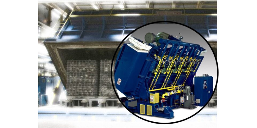
Heat Treat Today asked tip-up manufacturers to help heat treaters understand the variability of tip-up options in the market today. In this article, Gasbarre Thermal Processing Systems and Premier Furnace Specialists share unique approaches on how their own gargantuan furnaces serve heat treaters. As you read, note that customization is the critical component to operating a tip-up in your heat treat department.
This original content article is drawn from Heat Treat Today's February Air & Atmosphere Furnace Systemsprint edition. Have something to share about tip-up furnaces? Our editors would be interested in sharing it online at www.heattreattoday.com. Email Bethany Leone at bethany@heattreattoday.com with your own ideas!
Gasbarre Thermal Processing Systems
What is your system and how does it differ from historic tip-up systems?
Gasbarre has a unique offering of tip-up style furnaces. We offer systems for conventional applications such as austenitizing, solution treating, stress relieving, and tempering. In addition, we also offer atmosphere processes such as annealing and ferritic nitrocarburizing (FNC). For us, tip-up systems are not one-size-fits-all type systems. Systems are designed around our customer’s specific processing requirements. This would include thermal process requirements, load geometry and weight, temperature ranges and uniformity requirements, as well as time to quench specifications.
What are its operational advantages?
Contact us with your Reader Feedback!
When evaluating a tip-up furnace system, they are typically compared against box-style furnaces and car bottom furnaces. So, what differentiates a tip-up from these other style furnaces? First, you can achieve the main goal of large capacity batch processing, while gaining advantages over box furnaces with wider temperature ranges and tighter uniformity requirements. Box furnaces are more challenging to evenly distribute heat due to the large space requirement for the furnace door, where it is difficult to include heating elements or gas fired burners. Second, you can achieve faster time-to-quench speeds in a tip-up furnace over a car bottom furnace. Car bottom furnaces require the load to be pulled out of the furnace and then the load is typically manually moved from the furnace hearth to the quench. In a tip-up, this process can be automated and completed in 60 seconds or less. Finally, when special atmosphere processes are required, a tip-up furnace offers a superior atmosphere seal to the other furnaces mentioned. With tip-up furnaces, you can seal the furnace using its own weight. Other furnaces require additional mechanical assemblies to achieve a proper seal, which ultimately is more susceptible to leaks and requires more maintenance than a tip-up furnace seal.
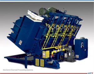
Tip-up furnace from Gasbarre Thermal Processing Systems Source: Gasbarre Thermal Processing Systems
Why should people be paying attention to what you have to offer?
Gasbarre’s broad product offering gives us the ability to evaluate your requirements objectively and offer the best solution for you and your company, whether that be box furnace, car bottom, or tip-up. Tip-up furnace systems are usually not one-off installations. These systems usually involve quenching equipment, material handling, load staging, and other integration. Gasbarre has the experience and personnel to manage such large projects and support the customer to effectively implement a system.
Premier Furnace Specialists
What is your system and how does it differ from historic tip-up systems?
The controls and automation capabilities of our furnaces set us above many older systems still in use today. On the control panel of an older system, you’re likely to see paper chart recorders, maybe a PanelView screen, and dozens of switches, pushbuttons, and pilot lights. Some of our customers prefer these control systems for their familiarity, and that’s fine because we are capable of building this style of enclosure, but most come to us for improvements or new systems entirely. Our standard panel comes with a 23.8” color touchscreen display that lets operators manage or record almost every aspect of the furnace’s operation. This package can be added to existing furnaces as well, as we have performed many control and combustion upgrades on older systems to keep them functional and reduce operating costs. We also offer tip-up furnaces that operate via jackscrews for customers who want to avoid the maintenance and flammability of hydraulics.
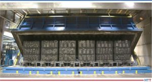
Open indirect gas-fired atmosphere furnace used to handle a variety of parts Source: Premier Furnace Specialists
Modern burner technology also offers a massive improvement over older systems. With rising energy costs for all fuel types, any increase in efficiency will quickly become a source of savings which can be redirected into other areas of your company. Improvements to burner design offer increased preheat, recuperative, and regenerative possibilities, which offer fuel savings across multiple temperature ranges and reduce emissions to keep in line with changing regulations. A standard burner can heat up and cool down faster, take less time to tune, and reduce maintenance hours and headaches compared to older models of burners with knowledgeable air and gas train design coupled with modern burners.
What are its operational advantages?
Our systems allow greater flexibility for integration with existing and future equipment as well as simplified operation. One of the largest complaints we hear in every industry is about the struggle to retain maintenance and equipment operators’ knowledge once a senior member leaves a company. For this reason, it is important to have a simplified controls interface that allows new operators to get up to speed quickly. As a service company as well as an OEM, we have extensive experience working on and upgrading many brands of equipment. This enables us to easily integrate our solutions to match what customers are familiar with while also reducing maintenance requirements.
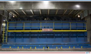
Closed furnace with work chamber of approx 31' x 9' x 9' with load capacit of 90,000 lbs. Source: Premier Furnace Specialists
Why should people be paying attention to what you have to offer?
Despite OEMs trying to convince you, sometimes a standard “cookie cutter” model just isn’t the right fit for a job. It can take years to build up a budget for a new furnace system. Don’t invest those hard earned dollars into a piece of equipment that won’t do everything you need, exactly how you need it done. We are willing to take on the jobs that require creative solutions and extensive automation. Premier’s custom engineered systems live up to our namesake. Some of our recent projects have included a 130 ft long roller hearth furnace system with automated cooling/sequencing/handling of over 40 loads simultaneously; and a car bottom furnace with a 15’ x 15’ x 15’ work chamber capable of controlled heating and cooling of 160,000-pound loads.
Find heat treating products and services when you search on Heat Treat Buyers Guide.com
CQI-9 compliance demands adherence to the standards for the purpose of excellence in automotive heat treating. Poorly maintained quench oil can cost heat treaters in many areas.
In this Heat TreatToday Technical Tuesday feature, Greg Steiger, senior key account manager at Idemitsu Lubricants America, shares how costly quench oil issues can be addressed through proper adherence to the CQI-9 quench oil testing protocols. Let us know if you’d like to see more Original Content features by emailing editor@heattreattoday.com.
Greg Steiger Sr. Key Account Manager Idemitsu Lubricants America
Introduction
A poorly maintained quench oil can cost a heat treater in more ways than simply the cost of having to replace the oil. The costs can quickly expand to include those associated with poor quality. For example, costs associated with part rejects, or rework and downstream costs for shot blasting, or third-party inspection are often the cause of poor quench oil maintenance. Dirty or poorly maintained oils can affect part cleanliness, surface hardness, and surface finish. For instance, it is well known that a heavily oxidized oil may create surface stains that must be shot blasted to remove. High molecular weight sludge or excessive water can create surface hardness issues. Many of these issues can be addressed through proper adherence to the quench oil testing protocols established by CQI-9.
How can CQI-9 help?
CQI-9 is designed as a tool to help heat treaters produce consistent parts. Using a CQI-9 compliant quench oil analysis can also be a very powerful tool in a heat treaters tool kit. Just as the level of carburization is influenced by the carbon potential of a carburizing atmosphere, the cooling speed of the oil influences microstructure formation and microstructure composition along with mechanical properties such as hardness as well as tensile and yield strength. Furthermore, the cooling speed is dependent upon the viscosity of the oil, the amount of sludge, moisture level, and oxidation of the oil. All of these are tested on a regular basis under the requirements of CQI-9, ISO TS 16949, and most quality systems adopted by modern heat treaters. All of the tested parameters required under CQI-9 will be addressed individually later in this paper.
What is CQI-9?
The member companies of the Automotive Industry Action Group (AIAG) encompassing automotive manufacturers and their Tier I suppliers have enacted an industry heat treating standard called CQI-91. This standard was originally a standalone standard designed and adhered to primarily by North American OEMs and Tier I suppliers as a quality tool to create consistent documented processes within the heat treating industry with the goal of producing consistent reproducible results. Since that first implementation of CQI-9, the standard has now been incorporated into the ISO TS 16949 standard and is now adhered to by most automotive OEMs and their Tier I suppliers. The full range of management responsibilities, material handling, and equipment operations of the CQI-9 standard is beyond the scope of this paper. Instead we will be discussing the used quench oil analysis requirements of CQI-9, why the tests are required, and how heat treaters need a CQI-9 compliant quench oil analysis to properly care for their quench oils.
Utilizing a compliant CQI-9 analysis and the supplier provided operating parameters for the CQI-9 required tests is the first step in the proper care of a quench oil.
CQI-9 Compliant Analysis
Most quench oil suppliers provide a quench oil analysis. Although the quench oil supplier may provide a quench oil analysis, for the analysis to be CQI-9 compliant the analysis must contain the following tests or their equivalent:
Water content; ASTM D6304
Suspended solids; ASTM D4055
Viscosity; ILASD509
Total acid value; ASTM D664
Flash point; ASTM D92
Cooling curve; JIS K2242
The frequency of the above testing must be a minimum of semiannually. A more frequent sampling interval does not violate CQI-9. In fact, the more often a quench oil is analyzed, the easier it is to use the quench oil analysis as a tool in the proper care of a quench oil. It is important to note that the CQI-9 standard does not prescribe specific test methods be used in the above testing; however, they must be performed to a traceable standard. The CQI-9 standard only states that the above values, along with a cooling curve, must be reported. The following sections will describe each test in a CQI-9 compliant analysis.
Water Content
Everyone knows water in a quench oil can be have catastrophic safety and performance consequences. However how much water is too much? That is a question that is difficult to answer. The answer depends on a variety of factors such as the quench oil used and all of the variables associated with a furnace atmosphere. A general rule of thumb when it comes to water levels is to keep the water level below 200PPM. At levels above 200PPM of water, uneven cooling begins to occur.2 It is important to remember a quench oil is not a pure homogenous fluid. Samples taken at various places throughout the quench tank will be similar but will also have differences. These differences will include water and solids levels. Therefore, in areas where the water content exceeds the 200PPM level, uneven cooling will begin. Parts coming into contact with this “localized” quench oil with high water can potentially begin to crack, have a high surface hardness, or have staining problems. Yet parts in other areas of the load continue to behave normally. For this reason, and also because water is much heavier than oil, it is imperative the oil be under agitation. In addition to the potential uneven cooling issues high water may create, a high level of water can also influence the rate of oxidation in an oil.
Suspended Solids
Because solids are typically denser and more viscous than liquids they do not have the same heat transfer properties as a liquid. Due to the inequality of heat transfer capacities between liquids and solids, it is very important to keep the solids level, especially high molecular weight sludge, at a minimum. Sludge reacts in an opposite manner of water. Where water can increase quench speed, high molecular weight sludge will decrease quench speed through uneven cooling.2 The result of the uneven cooling from sludge is typically seen in soft surface microstructures or soft surface hardness. Also, like water, sludge is heavier than oil and the lack of homogeneity in the oil means having proper agitation is paramount when sampling.
Viscosity
Changes in viscosity can lead to both faster quench rates and slower quench rates. As the quench oil is used in the quench process, it undergoes thermal degradation.3 This degradation process can be seen when the oil becomes thinner or less viscous. During this process, a small portion of the base oil and a small amount of the quench oil additives undergo a process called thermal cracking. In this process, heavier molecules are broken into smaller molecules through the use of heat. This thermal cracking creates lighter less viscous oil from heavier oils. The newer lighter viscosity of the quench oil can potentially lead to changes in the quench speed of the oil. These changes can have an impact on the microstructure, case depth, core hardness, and surface hardness on the quenched parts.
As an oil is subjected to the high temperatures of a quenching operation, oxidation is a natural occurrence in the oil. As the oil oxidizes it will begin to increase in viscosity until it reaches the point of forming an insoluble sludge. Therefore, an increase in viscosity typically means the oil is oxidizing. Just as an oil that becomes thinner and less viscous may have a change in cooling properties, an oil that becomes thicker and more viscous may see a change in cooling performance. A thicker oxidized quench oil may affect surface hardness, microstructure, case depth, and core hardness. In severe cases of oxidation staining may result. Such stains typically require post quench and temper processing such as shot blasting.
Total Acid Value
The Total Acid Value, or TAV, is a measure of the level of oxidation in a quench oil. The amount of oxygen in a quench oil cannot be measured without a sophisticated laboratory analysis. However, the formation of organic acids within a quench oil can be easily determined via a titration method. It is well understood that these organic acids are the precursors in a chain of chemical reactions that will eventually form sludge. As the TAV increases so will the levels of oxidation, and in turn, the amount of sludge will also increase. Consequently, as the TAV increases, the amount of staining due to oxidation may increase. The cooling properties of the oil may decrease due to the increased sludge formation as well. Figure #1 shows an example of how the acid value increases the viscosity of a quench oil due to the formation of polymeric sludge in the quench oil.2
Figure #1. Acid number vs kinematic viscosity for Daphne Hi Temp A
Flash point
The flash point of a quench oil is another check to ensure the safety of the quench oil user. As oil thermally cracks, the heavier base oils become not only lighter in viscosity, but their flash points also decrease. If left unchecked, the decrease in flash point could result in a higher risk of fire. In addition to serving as a watchdog against the results of excessive thermal cracking, a flash point is also a safeguard against human error and adding the wrong quench oil to a quench tank. High temperature oils typically have a higher flash point than conventional oils. An increase in flash point, along with no change in TAV, and an increase in viscosity could indicate a contamination issue between oils has occurred.
Cooling curve
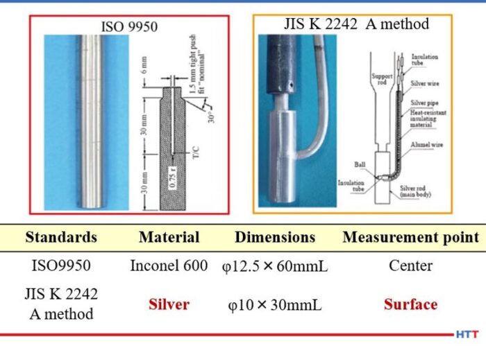
There are many different methods of running a cooling curve. Many Asian suppliers of quench oil will use the Japanese Industrial Standard (JIS) K 2242. European suppliers will use the ISO 9950 and North American suppliers rely on the ASTM D 6200 method. All of these standards measure the same basic property, the ability of an oil to reach martensite formation. However, they differ in one basic item. The JIS K-2242 and methods used in China and France use a 99.99% silver probe that is smaller than the size of the Inconel probe used in the ASTM and ISO methods of Europe and North America. Because of this difference, it is important to note that cooling curves and cooling rates between the methods should not be compared. Figure # 2 shows the comparison between the two probes and their dimensions.
Figure # 2. ASTM D-6200/ ISO- 9950 and JIS K 2242 quenchometer probes^2 ISO/ASTM Inconel probe 12.5mm x 60mm. JIS K 2242 Silver probe 10mm x 30 mm
In addition to comparing the cooling curve against the standard for the quench oil used, the Grossman H value should also be calculated and used as an indicator of cooling performance. Unlike the old GM nickel ball test that tracked the time to cool a 12mm nickel ball to 352°C, the Grossman H value measures the severity of the quench6.
In using the Grossman H value, the lower the value, the slower and less severe the quench. For use as a rough guide in comparing the quench speed in seconds to the Grossman H value measured in cm-1 the table below can be used.
Table #1
For example, air has an approximate H value of 0.01 cm-1 and water has an approximate H value of 0.4 cm-1 compared to oil with an approximate H value of ___ cm-1
The calculation used to determine the Grossman H factor has historically been:
H=h/2k
Where h is the heat transfer coefficient of the part when measured at the surface of the part and k is the thermal conductivity of the steel. Typically the heat transfer coefficient is measured at 705°C. A steel’s thermal conductivity does not typically change according to alloy composition or temperature. Therefore, the Grossman H value is proportional to the heat transfer coefficient of the part.
Interpreting a CQI-9 quench oil analysis
Table #2
Discussion
In examining the test parameters for CQI-9, it becomes apparent that many of the test results should be compared with other test results. For example an increase in the amount of sludge or solids should also increase the viscosity of the quench oil. As the sludge increases, the level of oxidation increases, and therefore, the level of organic acids formed in the quench oil should be increasing the TAV. Finally, as the sludge increases, the cooling property of the quench oil should decline as indicated in the lower H value.
Figure #3. Total Acid Value (TAV) and Grossman H value
Likewise, as the flash point decreases the amount of thermal cracking is increasing, which should reduce the viscosity and thereby increase the H value and the overall cooling speed of the quench oil. Conversely, if the test parameters are not working in concert with each other, there may be other issues going on within the quench oil. For instance, an increase in the water content can be detected before the increased water levels begin the oxidation process thereby increasing the TAV. Or a viscosity change without a change in other parameters could be an addition of the wrong quench oil to the quench tank. The graph below for Idemitsu Daphne Hi Temp A helps illustrate this point.
Figure #4. Graph for Idemitsu Daphne Hi Temp A demonstrating viscosity change
In the graph above, it can be seen when the water H value increases and the viscosity remains stable, the likely explanation is an increase in water. When both the H value and viscosity decrease, additive consumption is the most likely reason. Likewise, when the viscosity increases and the H value decreases, the formation of sludge from oxidation is the culprit.
Having test parameters that work in conjunction with each other is only beneficial if sample frequencies are often enough. While CQI-9 only stipulates a semi-annual sampling frequency, the conditions of a quench tank can change in very short order. There are the obvious changes when water is added to the tank. However, many of the changes are more subtle, and left unchecked over time can create potential costly solutions such as a partial dump and recharge of the quench tank, poor part quality, or an increase in downstream processing such as shot blasting. For this reason, many quench oil suppliers request a minimum of quarterly sampling. In addition, if a sample is missed on a quarterly sample frequency, there is still time to sample the quench tank and remain in compliance with CQI-9.
Conclusion
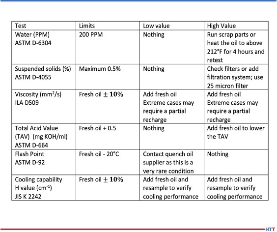
Over time the condition of a quench oil will change and corrective measures will be needed to bring the quench oil back into the suggested supplier’s operating parameters. The chart below helps understand what some of the methods need to be.
With proper care and maintenance, a quench oil can last a very long time. A conventional oil should last 10 to 15 years or longer while a marquench oil should last seven to 10 years. The proper care of a quench is simple and straight forward. A quality quench oil should not need the use of additives to improve oxidation resistance or quench speed. Simply adding enough fresh virgin oil to replace the oil that is being dragged out through normal operations should replenish the oxidation protection and quench speed to within the normal operating parameters. The table below offers recommendations for treating out of normal operating parameters for the required CQI-9 tests.
Recommendations for treating out of normal operating parameters for the required CQI-9 tests
Most heat treaters make weekly quench oil additions to their quench tanks. The most popular type of filtration system is a kidney loop style where the quench oil is constantly filtered. There are two basic types of these systems. They differ in the number of filters used. For a single filter system, a 25 micron filter is sufficient for quench oil filtration. In a two-stage filtration system, a 50 micron filter is typically used in the first stage and a 25 micron filter is used in the second stage. In a two-stage filter, the cheaper 50 micron filter will be replaced more often than the 25 micron filter in the second stage.
Utilizing a compliant CQI-9 analysis and the supplier provided operating parameters for the CQI-9 required tests is the first step in the proper care of a quench oil. The next basic steps are ensuring there is enough fresh quench oil available for regular additions to replace the oil that is lost through drag out and proper filtration of the quench oil in a constant kidney loop type of a system. With these steps in place, a quench oil will offer consistent performance for years and will be one less concern heat treaters face in the operation of their furnaces.
References:
Automotive Industry Action Group, “CQI9 “Special Process: Heat Treatment System Assessment;” AIAG version 3, 10/2011.
M.A. Grossman and M. Asimov. Hardenability and Quenching. 1940 Iron Age Vol. 107 No.17 Pp 25-29.
About the Author:
Greg Steiger is the senior key account manager of Idemitsu Lubricants America for quench products. Previous to this position, Steiger served in a variety of technical service, research and development, and sales marketing roles for Chemtool, Inc., Witco Chemical Company, Inc., D.A. Stuart Company, and Safety-Kleen, Inc. He obtained a BSc in Chemistry from the University of Illinois at Chicago and is currently pursuing a Master’s Degree in Materials Engineering at Auburn University. He is also a member of ASM International.
What have we learned these past six months? Well, for starters, everyone misses being face-to-face! Yet many heat treaters have taken this time to be flexible and innovative, building their intellectual fitness, so to speak.
This article, a Heat Treat Today Original Content piece, highlights some of the major themes which digital opportunities provide to heat treaters. You may note that some of these opportunities are still being offered; please reference company websites to confirm.
“COVID-19 came along… [but] it forced me to look into other projects which may be even more interesting. And I decided to build my intellectual property.”
-Harb Nayar, president of TAT Technologies, LLC on Heat Treat Radio
[spacer color=”3366FF” icon=”fa-lightbulb-o”]
Signs of life pre-April 2020 seem to be coming back, though many people are still reckoning with the work constraints. This past quarter, and even into Q3, heat treaters have seen a remarkable initiative to make learning online available. Heat Treat Today did a select study* of what a few of the most recent, heat treat specific events had to offer. The results of the examination demonstrates trends in the types of themes which heat treaters can improve their “intellectual fitness.”
Summary
A few themes stick out as key content: the fundamentals, quality control, additive manufacturing (AM) and 3D printing, and maintenance concerns.
source: Heat Treat Today
These themes were made available to heat treaters in the form of three main presentations: session or lecture format; panel discussion; round table. All platforms engaged in some form of online sessions which colored more lecture/seminar styled with scholarly professionals to addresses given by industry leaders or technical insiders. Larger, lengthier events, such as Furnaces North America and SECO/WARWICK’s e-Seminar incorporated panel discussions in addition to single-speaker sessions. Truly unique was the announced “round table” access at the Ceramics Expo Connect’s session on September 24th, “How to Improve Your Ceramic Products Material Properties Through Raw Material Optimization?”
Within these structures, a few presenters took advantage of the digital opportunity to offer case studies and live demonstrations of certain methods and processes. At the e-Seminar, multiple opportunities for this included “Symptoms of a Burner Issue – How to Solve It” and “Revealing the Secret of Carburizing,” while Buehler’sWilson Hardness Days (WHD) event promises “live demonstrations of DiaMet software.” Only a few of the events examined offered the opportunity to submit questions before the presentation occurred. Many sessions in this online forum were pre-recorded well in advance, so this might contribute as to why soliciting questions before the presentations wasn’t as widespread.
Four Themes of 2020
The Fundamentals
This one is not surprising. “The Fundamentals” refers to any overview, back-to-the-basics type of session that hits major ideas in the industry which might refine practices, but does not challenge or recreate heat treating theory/practice. An example of this is the technical session on day one of the FNA: “The Importance and the Proper Way to Monitor Polymer Quenches” to be given by Keisuke Kuroda of Idemitsu Lubricants America.
Hubbard-Hall’s webinar on cleaning titled “Optimizing Cleaning in Heat Treat Processes” promised to cover “the influence of contaminations in different heat treatment applications,” something that may not be as exciting as nitrogen gas quenching, but is still essential to know. At WHD, the event notes that “Machine Calibration and Servicing” will be a guaranteed part of the webinar on hardness testing.
Quality Control
Not to be confused with “The Fundamentals,” this theme encapsulates topics about implementing new theory and improving or refining current practice.
At the Ceramics Expo Connect, a session on “Powering a Mobile Future: The Role of Ceramics in Taking Solid State Batteries from Theory to Practice and Improving Lithium Ion Models” demonstrated this theme. If you attend the e-Seminar, you may have heard the panel “Maintenance in the Age of Industrial 4.0 Description,” which also falls into this theme. At a more particular level, Buehler will introduce the new Rockwell Tester at their event.
Additive Manufacturing and 3D Printing
At the cutting edge of industry development, these young applications in the heat treat world have been getting a lot of attention, with other forward-thinking topics on the horizon as well (like IoT and Industry 4.0). Buzz a constant buzz of these processes were apparent, particularly in the FNA 2020 schedule.
One of the technical session at FNA 2020 will be given by Dan Herring, the Heat Treat Dr., titled “Will Additive Manufacturing Add or Take Away Heat Treating?” At the e-Seminar, “3D Printing—Revolution or Evolution” was the title of one provocative panel discussion.
Maintenance
This is another big theme, and rightly so: maintenance concerns can cause problems with the heat treating process which could result in poor results, or dangerous outcomes.
FNA 2020 will be dealing with maintenance questions a lot over the next few days. On a micro-scale, Hubbard Hall’s webinar will be addressing these questions: “How closed cleaning machines contribute to cost efficiency and sustainability” and “How companies overcome specific cleaning challenges.”
Other Themes
“Troubleshooting” and “adapting to COVID-19” also stood out as recurring themes, though many sessions were concerned with these in relation to quality and future planning. Additionally, “COVID-19” in particular was considered during multi-day events as it related to pivoting one’s business strategy whereas single-day events focused on topics which are periphery to COVID-19 like “supply-chain” and “future of heat treat.”
Ok, But Does This Mean Anything?
Heat treaters are adaptive, responding to changes. But beyond picking up the latest item on the block, heat treaters want to make sure that their operations are reliable and excellent, hence the heavy focus on “The Fundamentals” and “Quality Control.” Testing new ideas and refining maintenance strategies are implemented, but it seems that this is typically after heat treaters know that they are performing with excellence in their day-to-day.
Further information on these events can be found on the company websites.
*The study focused on five of the most well-publicized and widely circulated events in the heat treat industry in August and September of 2020. The study is not meant to be exhaustive, but rather a case study of trends which may serve to be indicative of larger trends in the heat treat industry.
Heat treaters have their processes down to a science, literally. But what factor can compromise your heat treated part, let alone possibly cause detrimental damage to your facility?
Greg Steiger Sr. Key Account Manager Idemitsu Lubricants America
Michelle Bennett Quality Assurance Sr. Coordinator Idemitsu Lubricants America
Heat TreatToday is pleased to present this original content article for today's Technical Tuesday. Greg Steiger, senior key account manager at Idemitsu Lubricants America, and Michelle Bennett, quality assurance senior coordinator at Idemitsu Lubricants America, describe water contamination in quench oil, the effects of this contamination, and how to test and safely remove the water from the quench oil.
Introduction
Water is an amazing substance. Water helped create the Grand Canyon and Niagara Falls. When water freezes, it doesn’t contract like most materials. Instead, it expands and creates potholes that swallow up our cars every winter. As the temperature rises, water also expands. This property allows water to heat our homes and is why steam engines work. The thermal expansion of water as it turns into steam is what can create catastrophic events in a quench oil. This paper will look at potential water contamination sources in a quench oil, what the effects of the water can be, how to test for the presence of water in a quench oil, and how to safely remove the water from a quench oil.
Sources of water contamination
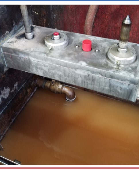
There are two major classifications of potential water contamination. The first source can be classified as potential internal sources of water. These potential sources are typically a part of heat treating furnace or oil cooling system. They include water-cooled bearings, fans, doors or heat exchangers. These water-cooled components are under a contestant pressure and will eventually leak. Because the quench tank is usually below these sources of water, the water will eventually find its way into the quench tank. Water-cooled bearings and fans are located within the furnace and are often directly above the quench tank. While a water-cooled door is typically not directly above a quench tank, it is in close proximity to the quench tank. This proximity will allow leaking water to enter the quench tank. Heat exchangers are typically situated away from the furnace. However, in a water-cooled heat exchanger, the water is never more than the wall thickness of the cooling tubes away from the oil. Should a cooling tube form a leak, the water and quench oil would simply mix within the cooling stream and the quench oil water mixture would return to the quench tank.
"The greatest risk of external water contamination lies in preventable operator or maintenance mistakes, especially when the equipment is down and open for maintenance."
The second classification is external sources. These sources of water contamination are not part of the heat treating furnace. Examples of external sources can be further broken down into leaks and operator or maintenance personnel mistakes. Leaks typically include fire extinguishers and fire suppression systems leaks, leaking fire resistant hydraulic systems, atmosphere leaks, pneumatic cylinders and building leaks. To prevent the leak type of contamination, routine maintenance, like a daily “Gemba” walk to spot any leaks, is the best defense against water entering a quench oil through a leak. The greatest risk of external water contamination lies in preventable operator or maintenance mistakes, especially when the equipment is down and open for maintenance.
Quite often when a furnace undergoes repairs, the quench oil is pumped out into empty totes to be reused after the furnace repair is finished. There is nothing wrong with doing this if the totes are clean. However, there have been reports of heat treaters doing this without first inspecting the totes to ensure that they are clean and free of any type of contamination. There have also been instances when the totes were not properly sealed and then stored outside, thus allowing rain water to get into the quench oil. But, the potential to add an incorrect product to the quench tank is a preventable operator error.
How water affects a quench oil
As previously mentioned, water expands as it turns into steam. At 212°F, water has a density of 0.96g/cm3.1 One gallon of water occupies 0.14 ft3. At one degree above boiling the steam from the boiling water has increased to occupy 224 ft3 and a density of 0.0006 g/cm3. The thermal expansion rate of water is approximately 1600%. What this means is the single gallon of water that was in the quench oil before it turned into steam now has a volume approaching 1600 gallons. In order for the 1600 gallons of steam to escape from the quench tank, it must displace an equal amount of quench oil. With nowhere to go, this displaced oil will find hot spots and open flames to create a catastrophic event.
Quench severity
Fig.1 Schematic of ASTM D-3520 (ref. 7)
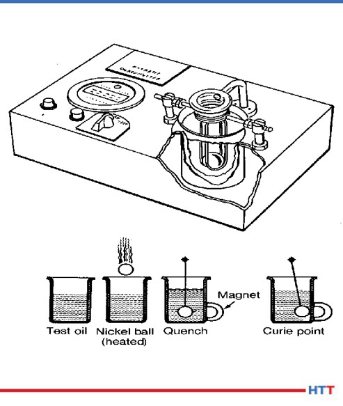
Historically, the severity of the quench has been measured by ASTM D-35202. In this method, a chromized nickel ball is heated to 885°C and is dropped through an electronic sensor, which starts a timer, and into a steel cylinder of quench oil in a magnetic field. Once the chromized nickel ball reaches the Currie temperature of nickel at 354°C, the ball becomes magnetic and closes the timing circuit when the ball comes into contact with the cylinder. The popularity of this test has always been that it provides a number that is easily interpreted by heat treaters to “rate” the oil as fast (9 – 11 seconds), “medium” (12 – 14 seconds), “slow” (15 – 20 seconds) or marquench (20 - 25 seconds). A schematic of the test method is shown in Figure #1.
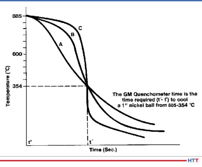
This test worked well to differentiate between different how well the quench oils cooled the nickel ball. The test really didn’t distinguish between the cooling characteristics of a quench oil. The test result in Figure #2show a time in seconds for the nickel ball to reach 354°C for three separate oils. However, when the actual cooling curves of the oils are examined there are three distinct cooling curves shown.
Fig. 2 Three separate cooling curves with the same quench speed as measured by ASTM D-3520 (ref. 7)
Because mechanical properties such as yield strength and hardness are dependent on the severity of the quench, the Grossman H value3 has become more popular over the years. In using the Grossman H value the lower the value the slower and less severe the quench. For instance air has an approximate H value of 0.01 cm-1 and water has an approximate H value of 0.4 cm-1. The calculation used to determine the Grossman H factor has historically been:
Where h is the heat transfer coefficient of the part when measured at the surface of the part and k is the thermal conductivity of the steel. Typically the heat transfer coefficient is measured at 705°C. A steel’s thermal conductivity does not typically change according to alloy composition or temperature. Therefore the Grossman H value is proportional to the heat transfer coefficient of the part.
Cooling curve
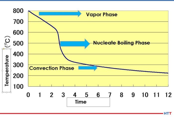
The basic cooling curve consists of three stages: the vapor blanket, nucleate boiling and convection. A basic cooling curve with the three different cooling phases is shown in Figure #3.
Fig.3 Three stage cooling curve (ref. 4)
In the vapor blanket stage, the load and the quench oil coming into contact with the load are above the evaporation temperature of the oil. An insulating vapor blanket forms around the load and no cooling occurs. Because the vapor blanket is insulating and does not allow for cooling, the vapor stage carries the highest risk of distortion.4 Once the vapor pressure decreases to a point where the oil can once again condense on the load and the temperature of the oil falls below the evaporation temperature, the nucleate boiling stage begins. In this stage, the load undergoes the most aggressive cooling. After sufficient cooling has occurred and the quench oil temperature is below the boiling temperature of the oil, a smooth transition into the convection stage begins.
Stabilization of the vapor stage
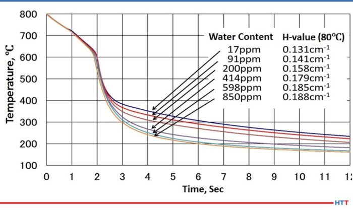
As water is dispersed throughout the oil, the viscosity of the oil changes. As the amount of water increases, the viscosity of the oil also increases.5 A careful examination of Figure #4 will also show a slight movement of the cooling curve to the left and a lengthening of the vapor stage as the amount of water increases. Furthermore the water in the oil is not uniformly dispersed, and this non-uniform dispersion creates uneven cooling rates throughout the oil. To restore even cooling, it is recommended the water in the quench oil be reduced to below 200 PPM.
Fig. 4 Cooling curve change due to water contamination (ref. 4)
Types of water found in a quench oil
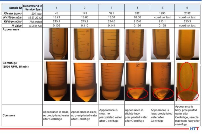
In simplistic terms, water in a quench oil can be thought of as being dispersed in the quench oil due to agitation or as free water having exceeded the saturation point of the oil. As a general rule of thumb in the industry, the saturation point is considered to be 0.1% or 1,000 PPM. However, the saturation point will vary according to the temperature of the oil and the additives within the quench oil. Daphne Hi Temp A-U is a good example of a clear amber quench oil. Figure #5 shows a picture array of the appearance of the oil as the amount of water approaches and then exceeds the 1000 PPM industry standard.
Fig. 5 Daphne Hi Temp A-U appearance as the amount of water dispersed within the oil nears and exceeds the saturation point of the oil. (Used with permission Idemitsu Lubricants America)
Notice in the data above that as the amount of water increases in the Daphne Hi Temp A-U, so does the viscosity as measured at 100°C. In addition to the viscosity rising as the amount of dispersed water increases, so also does the quench severity as measured by the Grossman H value. Furthermore, the appearance of the quench oil changes as the amount of water increases as well. (See Fig. 5 for the Daphne Hi Temp A-U.) With small amounts of dispersed water—45 PPM—the quench oil is clear and there is no water that is precipitated out after centrifuging for 15 minutes at 5500 RPM. However, as the amount of water begins to approach the 1000 PPM level, the appearance of the quench oil begins to become hazy. As the saturation point is exceeded, the appearance remains hazy and water precipitates out after centrifuging for 15 minutes at 5500 RPM.
Testing for oil in a quench oil
There are two basic types of testing methods for determining if there is water dispersed in a quench oil. One of the methods is subjective and the other is quantitative. The crackle test involves heating a metal coupon to approximately 400°F and placing a few drops of the quench oil on the surface. If there is a sufficient amount of water in the oil visible bubbling within the oil and audible crackling will occur. Unfortunately, this is typically above the saturation point of the quench oil. At which point it is often too late. Figure #6 shows examples of crackle testing.
Fig. 6 Crackle test results for Daphne Hi Temp A-U
The second and preferred testing method is through ASTM D-6304 Standard Test Method for Determination of Water in Petroleum Products, Lubricating Oils and Additives by Coulometric Karl Fisher Titration6. The Karl Fisher test uses the Bunsen electrochemical reaction to calculate the amount of water in a used oil and is accurate in used oil from 1 PPM to 50,000 PPM.
Removing water from a quench oil
Removing excessive water from a quench oil can be achieved economically through several methods. Table #1 is a brief trouble shooting guide to the safe removal of water from a quench oil.
Table 1 Trouble shooting guide for removal of water from a quench oil
Conclusion
Finding small amounts of water, less than 50 PPM is very common in a used quench oil sample. This small amount could simply be condensation within the bottle and quench tank. However,when the amount of water begins to reach levels above 200 PPM, troubles can begin. At levels above 200 PPM of water, the following may occur:
Uneven cooling due to non-uniform dispersing of the water within the quench oil
Increase in viscosity
Increase in Grossman H Value
Lengthening of the vapor blanket stage
Increase in the severity of the quench
Like most materials, water expands as it changes from a liquid into a vapor. With a thermal expansion rate of 1600%, a gallon of water turns into considerable more steam. Therefore excessive water transitioning into steam in a quench oil creates safety concerns when the steam forces the quench oil from the tank. Examples of these safety concerns are:
Risk of harm and injury to plant personnel
Damage to furnaces and related equipment
Damage to the heat treat facility the surrounding plant and nearby buildings
Severe cases can result in a quench oil fire or a building fire
The importance of a “Gemba" walk should not be overlooked. Water can enter into quench oil systems through normal heat treating operations such as a leak in a water-cooled piece of equipment, others can be from preventable sources such as a building leak or other human error. No matter what the source is, if water is suspected in a quench oil, the quench tank should be sampled and tested before it is used.
References:
Handbook of Chemistry and Physics. 60th edition CRC Press, p. E-18.
ASTM International, “Standard Test Method for Standard Time of Heat Treating Fluids (Magnetic Quenchometer Method),” American Society for Standards and Materials.
M. A. Grossman and M. Asimov, “Hardenability and Quenching,” 1940, Iron Age Vol. 107 no.17, p. 25-29.
ASTM International, "ASTM D-6304 Standard Test Method for Determination of Water in Petroleum Products, Lubricating Oils and Additives Coulometric Karl Fischer Titration," West Conshohocken, ASTM International, 2016.
B. Lisic and G.E. Totten, "From GM Quenchometer Via Cooling Curve Analysis to Temperature Gradient Method," ASM Proceedings: Heat Treating, 18th Conference, 1998.
About the Authors:
Greg Steiger is the senior key account manager of Idemitsu Lubricants America for quench products. Previous to this position, Steiger served in a variety of technical service, research and development, and sales marketing roles for Chemtool, Inc., Witco Chemical Company, Inc., D.A. Stuart Company, and Safety-Kleen, Inc. He obtained a BSc in Chemistry from the University of Illinois at Chicago and is currently pursuing a Master’s Degree in Materials Engineering at Auburn University. He is also a member of ASM International.
Michelle Bennett is the quality assurance senior coordinator at Idemitsu Lubricants America, supervising the company's I-LAS used oil analysis program. Over the past 9 years, she has worked in the quality control lab and the research and development department. Her bachelor’s degree is in Chemistry from Indiana University.
"The success of most heat treating processes comes down to the battle between time v. temperature..." In this Heat Treat Today Technical Tuesday article, Jerry Dwyer of Hubbard-Hall describes innovative heat treating practices with organic polymer quenchants.
If you are interested in learning about what these polymer quenchants can do, and want to know specifically how a high-performing polymer reacts in the quenching process, read on for the details from a specific case study. Between time and temperature, you may just get the best of both worlds.
The success of most heat treating processes comes down to the battle between time vs. temperature, better known as isothermal transformation. The delicate balance between how long to quench a part and at what temperature often comes down to which media is being used to do the quenching.
Image of a clean machine
For decades, water and oil have been the go-to solution for quenching heat-treated parts in order to harden them to proper specifications. Of the two, water has the highest cooling rates (between 2,000°F/sec to 10,000°F/sec), which often leads to high distortion rates in parts and more cracking because of the high residual stresses. Oil-based solutions have been used extensively in the metalworking industry on larger, thicker parts because it has basically three cooling speeds: slow for lower hardness and less distortion, medium for when moderate to high hardenability is needed, and high for carburized and carbo-nitriding part applications.
But with increasing concern for both environmental disposal and safety issues, many heat treaters have been searching for an alternative quenching technology that meets their needs. With water and oil so prevalent, industry researchers developed a hybrid of the two in order to come up with a series of polymer quenchants that serve numerous functions and also reduce some concerns.
Development of Polymer Quenchants
Image of polymer
The polymer quenchants contain organic inhibitors and other additives that produce concentrates, which are diluted for use. The advantage of polymer solutions is that they have widely variant properties, which give a heat treater flexibility in how they use the product compared to just water or oil. They are also non-flammable, which eliminates the need for operators to install needed fire suppressant equipment that might be needed with other quenching methods.
There are several different types of organic polymer quenchants, including polyalkylene glycol (PAG), sodium polyacrylate (ACR), polyvinyl pyrrolidone (PVP), and polyethyl oxazoline (PEO).
The polyalkylene glycol (PAG) polymer is one of the most widely used in the heat treating industry and provides an ideal uniform cooling for minimizing distortion and preventing crack formation during hardening machine components and tools. Scott Papst, vice president of specialty sales and business development at Hubbard-Hall, says that many of their customers have inquired about adding a polymer quenching alternative to their process.
“The technology of the polymer process has grown tremendously over the years, and we wanted to make sure we had that technology in their hands,” Papst says.
Partnership with Idemitsu Grows Offerings
Hubbard-Hall, which has a line of several heat-transfer and heat-treat salts for annealing, martempering, isothermal quenching and other applications, began to look for a partner company to supply its customers with polymer quenchants and set their sights on Idemitsu Kosan Co., a Japanese energy company that owns and operates oil platforms and refineries, and manufactures numerous petroleum, oils and petrochemical products.
“We found Idemitsu to be a wonderful partner which has a tremendous focus on advanced technology, especially when it came to heat treating,” Papst says. “We were very happy when we could put together a partnership to offer their polymer quenches to the U.S. market.”
Polymer quenches are used primarily in what is called an “induction hardening operation.” An electric current is put through a copper coil to create a magnetic flux that heats up the target section of the part. Induction hardening uses a shorter time to harden the targeted section of the part instead of using an atmosphere furnace to heat treat the entire part.
Where salt quenches are used to heat treat an entire part, the polymer quenches can be targeted to certain areas of a parts, such as gear teeth. Greg Steiger, a senior key account manager for quench products at Idemitsu, says polymer quenches work great on parts like gears because it treats the most vital sections of the part.
“A gear has to be hardened because it needs to withstand a lot of wear-and-tear; but the teeth take the brunt of the load when the part is in use,” Steiger says. “The teeth of the gear have to be harder than the rest of the part; if the entire gear was as a hard as just the teeth, then that part would fracture and shatter.”
Benefits of Inverse Solubility
Polyalkylene glycols utilize inverse solubility in water; while they are completely soluble at room temperature, they become insoluble at higher temperatures from 140°F to 195°F, depending upon chemical structure. Inverse solubility controls the cooling and quenching mechanism. The ability to vary the concentration of a polymer quench provides great flexibility of the cooling rate. The polymer separates from water as an insoluble phase, and the ensuing deposited layer becomes as an insulator that determines the rate of heat extraction from the quenched part.
“The polymer slows the cooling compared to water, and controls the heat treating process” Steiger says. “The transformation rate is much more controllable, which makes the heat treating more tailorable to the part.”
Image with the door closed
Image of a door before process
Idemitsu’s high-performance polymer quenchant is its Daphne Plastic Quench HF, which has excellent oxidation stability performance that protects the integrity of the quenchant even after contamination by metalworking fluids. Steiger says Daphne Plastic Quench HF virtually eliminates the formation of sticky films common in most quenching polymers, which reducing the amount of drag out and thus reducing consumption.
“It is formulated to provide superior biocidal protection, preventing bacterial contamination in the recirculating induction hardening systems,” he says. “It also offers outstanding rust and corrosion prevention to better protect quenched parts. It is highly resistant to degradation.”
Lower Viscosity, Improved Efficiency
The Daphne Plastic Quench HF has a viscosity (at 104°F/40°C) of 29.5 mm2/s, which bests its two top competitors at 536.1 and 301.7. The lower viscosity improves handling and production efficiency, and also reduces or eliminates sticky build-up on machines, gauges, fixtures and parts.
The product also has excellent rust preventative properties and is thermally stable. In fact, Steiger says, testing with a Tier I parts supplier who was having rust issues with a competitor’s product showed that Daphne Plastic Quench HF has stable cooling performance after six months of use, and they only recharged their system twice in a year, reducing consumption by over 66%.
Further, when a global automotive OEM switched to Daphne Plastic Quench HF from a competitor, the result was better separation from tramp oils. The previous product was causing unstable cooling performance that resulted in cracks on the parts; it turns out the OEM was dumping machines and recharging every three months because tramp oil contamination become more than 5%.
“The actual quench oil usage by the OEM was reduced by up to 75% after just four months, and their sump life was much longer at more than six months,” Steiger says. “Lower concentrate usage and a significant reduction in residue directly correlates to improved productivity, reduced maintenance costs and lower disposal costs.”
About the Author: Jerry Dwyer is Hubbard-Hall’s market manager for product groups pertaining to heat treating, phosphates and black oxide. To learn more or get in touch, please visit Hubbard-Hall's website.
Metallurgists need accurate specifications in order to correctly perform the necessary heat treatment of parts. This helpful guide, written by William Rassieur, Sales Leader at Paulo Heat Treating, is a useful tool to identify what details ought to be communicated to the heat treating expert. Read below to understand the terms to pass along.
William Rassieur, Sales Leader, Paulo Heat Treating
Too often, metallurgists receive inadequate heat treatment specifications. Some specs contain too little information. Some are unclear. Some are just plain wrong.
In any case, inadequate specs mean heat treaters don’t have the information they need to deliver finished parts that can stand up to the applications intended by their manufacturers. Avoiding the confusion and delays that follow comes down to understanding what heat treaters need to see in heat treatment specifications so that the right treatment is applied.
Make certain your parts get the appropriate treatment by including the following information:
Clearly identified materials
The chemical makeup of a part is one of the most critical determinants of how it is heat treated. It’s not enough to state on the spec that a piece is steel alloy. Consult materials standards and use the correct material designation on the spec.
For example, if you want to treat a carbon steel or an engineering alloy, using those terms (or known trade names for a specific material) isn’t adequate. Good heat treatment specifications include the material as expressed in the standards—AISI 1040 for a carbon steel, for example, or SAE 4140 for an engineering alloy.
Specific process required
It’s not enough to tell a heat treater you’d like a harder part because there are many ways to do that. Does it need to be through hardened? Case hardened? Does it require stress relief via annealing?
Specs that dictate which process is to be used help heat treaters shape the rest of the heat treatment steps that follow.
Hardness tolerance
For through hardened parts, a prescribed hardness should be included on the spec and expressed as a range. Tolerances are always more useful than uniform hardness levels because parts can have different hardness values in different regions due to material thickness or closeness to an edge.
Engineers should note that the materials and dimensions of a part affect how well it hardens out. As these variables change, so does the acceptable hardness tolerance that should appear on a spec.
Case depth tolerance
For case hardened materials (i.e., those that are carburized or carbonitrided), specs should indicate whether the desired hardness is expressed as effective case depth or total case depth.
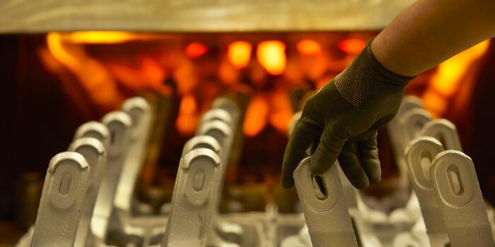
Case Hardening (photo source: Paulo.com)
Total case depth refers to the distance carbon has diffused into the part. This is usually specified for parts that have thinner case depths after treatment. Effective case depth applies to parts with generally thicker cases. This is measured as the distance from the surface through the case to a specific hardness level. Usually, that hardness is effective based from 50 or 52 HRC. This should always be stated on specs.
Heat treatment specifications should also identify the case tolerance, or the range of depths the prescribed hardness should reach. For example, a good spec for the heat treatment of a theoretical gear might state the effective case depth should be between 0.007 and 0.012 inches at the prescribed hardness.
As with through hardening, it’s more useful and realistic to specify minimum and maximum case depths rather than to write specs with a single case depth. Specs that include only minimum or maximum case depths still leave too much to interpretation and should be avoided.
Avoid too much information
Sometimes, though, too much specificity can lead to trouble. Specs that include too much process information can paint metallurgists into a corner, forcing them to abide by strict requirements that can end up thwarting their efforts to deliver improved parts.
For example, if a tempering spec includes both a specified temperature and a specified hardness, the hardness may not be possible to achieve due to differences in equipment. In such a scenario, metallurgists advise that specs be amended to call for a minimum temper as long as the part’s configuration and material hardenability are capable of achieving it.
Correct hardness scales
The scale on which a part’s hardness is determined depends on the heat treatment applied to the part. In the U.S., we typically use the following four hardness scales: Rockwell Hardness, Brinell Hardness, Microhardness, and Leeb Hardness. Become familiar with each scale and which parts and processes should be tested with each.
Also note that conversions between hardness scales should be avoided unless it’s absolutely necessary. That’s because hardness values are approximate; converting from one approximation to another compounds variation and could lead heat treaters and owners to incorrectly assume the prescribed hardness has been achieved.
Inspection points
Heat treatments are carefully designed to achieve specific results on specific areas of parts, so owners need to clearly identify those areas on which hardness tests are to be conducted.
For example, the critical part of the theoretical gear mentioned above is its teeth; case hardening is designed to strengthen that part of the gear while leaving other areas relatively soft and ductile. Applying a hardness test anywhere else but the teeth won’t inform heat treaters of whether the treatment was successful.
Be prescriptive with heat treatment specifications
Problems with heat treatment specifications are one of the biggest —and perhaps the most avoidable— pain points in the relationship between a manufacturer and heat treater. Manufacturers need finished parts that perform as promised. Armed with accurate and descriptive heat treatment specifications, heat treaters can deliver that performance.
For more information, contact the quoting team at Paulo or download Paulo's guide for in-house versus out-source handling of heat treatment needs.
In the wake of COVID-19, suppliers and manufacturers in the heat treat industry has found ways to educate and convene with one another using digital classes, seminars, conferences and more. This Heat Treat Learning article highlights some of the most prominent events which you can attend from your home or office. The list features events by date.
If you have attended or will be attending an online event, please consider emailing the editors at editor@heattreattoday.com or bethany@heattreattoday.com to share your impressions of the event value.
Classes and Webinars
Fractography and Fracture Analysis: History and Development: Tuesday July 28, 2020, 2:00 PM - 3:00 PM EDT
(photo source: Wynn Pointaux from Pixabay.com)
This free webinar will explore the background of fractography and fracture analysis with Daniel Grice, P.E. Senior Engineer and Larry D. Hanke, P.E., FASM, Principal Engineer Materials Evaluation and Engineering Inc. The event, supported by ASM International, is intended to help anyone who is interested in learning more about material behavior. Read more and register here.
How Verification of Medical Device Surfaces in Production Eases Product Development: Wednesday July 29, 2020, 2:00 PM - 3:00 PM EDT
Operating in different time-zones and featuring a recording to any participant who signs up, this free webinar intends to help metallurgical technicians, engineers, quality control and laboratory managers better understand their surface coatings. The webinar, supported by Buehler, will mainly be focusing on preparation challenges and approaches to achieve good quality, efficient preparation, accurate measurement and correct evaluation of these coatings. Read more and register here.
Elizabeth Kidd, Materials Scientist and Lucas Dillingham, Senior Applications Specialist at BTG Labs
This event targets medical device manufacturers concerned with verification of cleaning, coating, sealing, printing, or bonding. BTG Labs is making this webinar available for free. The speakers are Elizabeth Kidd, Materials Scientist and Lucas Dillingham, Senior Applications Specialist at BTG Labs. Read more and register here.
Heat Treatment 4.0 e-SEMINAR: Wednesday September 9, 2020, 3:00 – 6:00 P.M CET
This international event, conducted in English, features 9 hours of content over a 3 hour period with three topical meeting rooms. Recordings of the event will be made available to all participants for a short time following the event. The site claims that this will be the “first industry virtual meeting of international specialists” including both practitioners and scientists. Additionally, the seminar will serve as a platform to interchange ideas and technologies, share expert experience, and discuss industry in the current times. Hosting this event is SECO/WARWICK. For specific details on the event, read more and here.
ASM Virtual Classrooms: Continual
These online courses listings provide self-guided classes provide professional development opportunities to any students of metallurgy. With quizzes and a final examination, these courses provide certificates of completion for passing (80% or above) the course requirements. A few attributes that one may see in classes are flash animations, video of instructors teaching the course in a classroom, video segments from ASM's DVD series, and PDF's of instructor PowerPoints used in the instructor led trainings. Among course offerings are the Basics of Heat Treat, Component Failure Analysis, and short courses on topics like corrosion. For more details on how to enroll, read more and register here.
Online Opportunities
Not all learning has to be done in a cohort, although community does provide great motivation and a sense of accomplishment. Here is a selection of alternative digital information outlets to access while you are on the go or at home.
Blogs:For the readers
(photosource: tav-vacuumfurnaces.org)
TAV: The Vacuum Furnaces Blog - "Perfect Vacuum Sintering Step by Step [3/4]." Part of a larger series, you can find more via the referenced articles internally linked in this article.
Dan Herring's articles. Check out most heat treat news sources and you are sure to find them.
Ipsen's The Herald. Also, be sure to check out their white papers on their website.
Podcasts:For the drivers
Heat Treat Radio: Re-envisioning your international business? Interested in harnessing the research power of Worchester Polytechnic Institute? Here is just one outlet while you are on your daily drive.
Videos:For the entertainers
Heat Treat Marketing Minute: For advertisers, learn a new skill, hone your marketing technique, use more color in your advertising... all here at Heat Treat Today. Check in with Doug in his commentary on ROI.
MetallurgyData with Neil Hardy: You may remember the young producer of metallurgical content, Neil Hardy. Links to his YouTube and some background on the project can be accessed here.
Tom Ott's LinkedIn videos: Scan LinkedIn and you will find Tom Ott's videos, which come in handy for the tech savvy heat treater.
Heat TreatToday’s 40 Under 40 was created to bring recognition to young professionals in the industry, giving names, faces, and words to the rising generation of industry professionals. In this article, released in the final nomination period for Heat TreatToday’s 40 Under 40 Class of 2020, exemplary classmates from previous years share their views on the industry, giving words of encouragement to other young professionals, both current and future.
Kyle Hummel, P.E.,Sr Metallurgical Engineer at Contour Hardening
In 2019, Kyle was nominated by Contour Hardening to receive the 40 Under 40 recognition. Since receiving the nomination, Kyle has begun an Executive MBA program at Purdue to, “expand my education in business and leadership,” Kyle wrote, “in order to improve my effectiveness in my current position as well as prepare myself for future roles.”
Over the years, Kyle has found the broad range of processes and technologies in the heat treat industry to be appealing. The heat treat industry, Kyle noted, “can offer the perfect balance of hands on work experience as well as quality and process improvement that can keep you engaged for years as you grow your career. Another advantage is that heat treaters typically supply a number of different industries, so you can get experience in multiple fields that will help steer your career choices.”
Similarly, Matt Clinite was recognized in last year’s 40 Under 40 Class of 2019. Over the past year, Matt has been leading his remote team of regional sales engineers, who help Ipsen’s customers secure aftermarket parts, retrofits, and field service technicians. For him, the switch to online platforms and less face-to-face contact in the era of COVID has brought him to consider the fact that the “forced adjustment” may have lasting effects on business in years to come. “For many of us extroverted professionals,” wrote Matt, “[it] is a real bummer, but I’m optimistic this will be a blip in time, and some day we will be able to continue meeting face to face.”
As a 31 years old young professional, a manager, and a father of two, Matt has critical insight into hiring and maintaining future young leaders: While many believe that the industry needs to attract young people, Matt flips the onus saying, “If you ask 10 successful people in the industry to tell you their story, 9 of them will say they fell into the industry by accident…the industry needs to retain the young people that ‘fall’ [in].” His suggestions are that employers take care of their young employees and “provide a career path that will allow them to grow financially and professionally.”
For young professionals beginning in this industry, both Kyle and Matt emphasize the importance of initiative and focused learning, especially on the job.
Kyle Hummel, Contour Hardening
“Learn as much as you can, and get out on the floor and understand the equipment and talk to the people who have been working in heat treat for years.” – Kyle Hummel
“Find someone who can be a mentor to you and help you through the learning curve – working with huge expensive furnaces and equipment can be intimidating at first, and having someone help guide you through the process will be very beneficial.” – Kyle Hummel
“Take it upon yourself to become known inside your organization. Find ways to get in front of senior leadership and the technical staff. Once they know who you are, find ways to continually insert yourself into projects and discussions with them.” – Matt Clinite
When invited to important meetings or discussions early on, “It’s ok (and often times
best) to sit back and simply listen to the discussion. Take it all in and become a sponge.” – Matt Clinite
“Don’t be afraid to request meetings with leadership around topics such as: career advancement, merit increases or to voice your ideas.” – Matt Clinite
The Role of 40 Under 40
These two honorees, as well as fellow classmate Tim Mohr, Director of Strategic Programs at Paulo, and 2018 honoree, Danielle Cote at Worcester Polytechnic Institute (WPI), explained how the recognition has benefited them, and why they would encourage others to nominate their young colleagues this year or in future years.
Matt Clinite, Ipsen USA
Kyle Hummel: “Being a part of the 40 Under 40 class assists in making those connections to current or future customers, suppliers, or even competitors that you might not have made otherwise. Heat treat is a close knit industry, and you never know when you will work with one of the other 40 under 40 winners, so it is nice to have that connection.”
Danielle Cote: Professor Cote indicated thankfulness of the honor to be a part of 40 Under 40 Class of 2018 as it provided recognition to an unrecognized field. Hear her full message at this link.
Matt Clinite: “It’s a fun thing to “tout” at the trade show and to post on LinkedIn. And of course to share the magazine with family and friends always makes for good dinner table talk. To me the best part is the comradery. I really enjoyed reaching out to (and having been reached out to) by other recipients… In 2019 I felt flattered when a well-recognized individual from the industry nominated me. I hope I can show other young professionals in the industry my appreciation by nominating them.”
Tim Mohr: Tim also recognized the networking value of his nomination. He says that his acceptance into the 40 Under 40 Class of 2019 allowed him to meet new people throughout the industry. Listen to his full testimonial below.
Read more: If you haven’t already, head over to Heat TreatToday’s 40 Under 40 to nominate a young professional in the industry.
(photo source: Hirvana Arvizu Soyhivan on www.unsplash.com)
In today’s article, Heat Treat Today’s editorial staff has gathered noteworthy reflections of heat treaters who are looking to the past to offer hope to present circumstances. Read more to see that while the present seems paused with Covid-19, the past offers promise of growth and change through challenges.
Like many markets, the heat treating industry is seeking to make the best out of this summer of 2020, and even though the market is looking more positive by the day, there are many who still look for a sense of normalcy. However, with leaders looking at historical moments in heat treat, they remind us that while the present seems paused with Covid-19, the past offers promise of growth and change through the challenges of life.
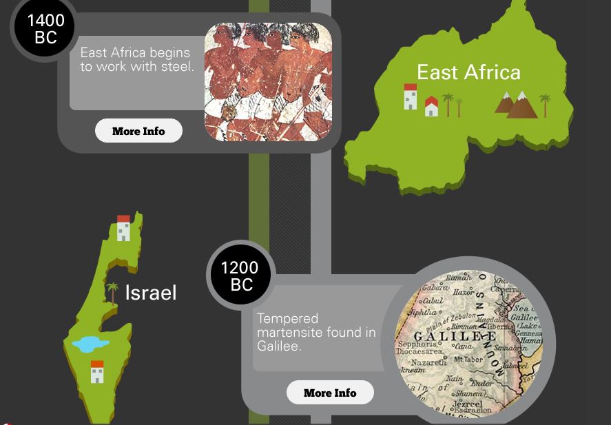
Sceenshot of Bodycote’s “An Interactive History of Metallurgy” (photo source: https://www.bodycote.com/history-of-metal/)
A major reach into the past is a throwback to the 90th century BC called “An Interactive History of Metallurgy.” In this historical timeline, Bodycote presents an engaging look at copper, bronze, iron, and tin through the centuries. The developments include detailed information, mostly funneled from Wikipedia, like the fact that bronze alloy in 12th century English candlesticks contained a degree of silver, antimony, and arsenic. And the modern, continuous development of steel is believed to have begun in the carbon furnaces of Sub-Saharan African communities.
(photo source: SECO/WARWICK)
On June 30, 2020, SECO/WARWICK released an “anniversary reflection” to commemorate the achievements of the Group in the first half of 2020. Among these is the 10th anniversary of their Chinese branch which has now become a recognized leader of CAB systems in heat treat, creating furnaces for aluminum brazing in controlled atmospheres. They conclude their message with a word from Sławomir Woźniak, President of the ManagementBoard, saying, “We wish that health, patience and faith – embracing the world at large – will return to normal.”
Sanderson’s Weir (photo source: Shane Higgins on LinkedIn)
Finally, a recent LinkedIn post from Shane Higgins, Field Sales from Special Quality AlloysLtd, shared a lunch-time crowd favorite: Sanderson’s Weir, built in the 1580s. With two iron forges on either side of the River Don in Sheffield, this low dam was built to provide power to the industrial work. Changes in the nature of industry has allowed a 20-year project along the River Don in Sheffield and Rotherham to permit a fish pass for salmon after 200 years without. It is impressive that the location that once produced iron still houses metalworking business.