As heat treaters strive for a sustainable future, pressure mounts to make the right choices while running commercially viable operations. This guest column by Michael Mouilleseaux, general manager at Erie Steel, Ltd., explores how and why heat treat operations are now coming under the focus of the U.S. Department of Energy.
This informative piece was first released inHeat Treat Today’s March 2024 Aerospace print edition.
The iron and steel industry contributes approximately 2.1% of energy-related CO2 emissions from primary sectors in the U.S. These statistics may seem insignificant or far removed, but the federal government has now determined that heat treating is a significant contributor and has set in motion critical changes for U.S. heat treaters.
Background
Click to share your Reader Feedback!
On December 8, 2021, President Joe Biden issued an executive order that committed the federal government to “lead by example” in U.S. efforts towards carbon-free and net zero emissions solutions. Since then, the executive has delegated the Department of Energy (DOE) and the Environmental Protection Agency (EPA) to spearhead these initiatives aimed at reducing greenhouse gas emissions (GHGE) and promoting energy efficiency across various sectors of the U.S. economy. To support these efforts, $10,000,000,000 in incentives are being allocated for the DOE and EPA to investigate and promulgate regulations.
Specifically, the government sees the “industrial sector” as responsible for close to a quarter of all greenhouse gas emissions (GHGE); the five industries named within this sector are chemical processing, petroleum processing, iron & steel production, cement production, and food & beverage manufacturing. The DOE is leading the efforts of “supercharging industrial decarbonization innovation” and leveraging the potential of “clean hydrogen.”
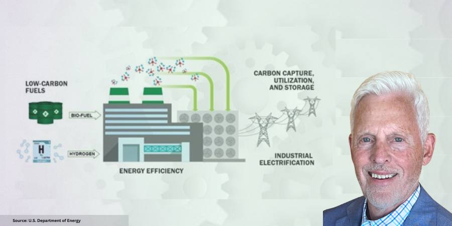
Following these directives, the DOE unveiled the “Industrial Decarbonization Roadmap” in September 2022. This strategic plan will guide decarbonization efforts of the five key industrial sectors to mitigate GHGE. The four pillars are:
Energy efficiency
Industrial electrification (using green electricity)
Adoption of low-carbon fuels, feedstocks, and energy sources (LCFFES)
Carbon capture, utilization, and storage at the generated source (CCUS)
The DOE determined that process heating — accounting for 63% of energy usage within the iron and steel industry — would be the best opportunity to apply these four pillars. However, until May 2023, heat treating had not been explicitly mentioned as a target for decarbonization efforts.
Why Should Heat Treaters Care?
In May 2023, the Industrial Efficiency & Decarbonization Office — an office within the DOE’s Office of Energy Efficiency & Renewable Energy — held a symposium to refine its commitment to the decarbonization of the industrial sector. It was then that heat treating was specifically defined as a process targeted for the reduction of GHGE in the steel, aluminum, and glass manufacturing industries.
The DOE’s refined commitment focuses on two things: reduce GHGE attributable to “process heating” by 85% by 2035 and achieve net-zero CO2 emissions by 2050. To reach these ambitious goals, the DOE emphasized the importance of adopting LCFFES, green electrification, and implementing strategies that promote industrial flexibility, advanced heat management, smart manufacturing, and alternative technologies.
The potential ramifications of the DOE’s efforts on the heat treating industry are momentous. With the development of regulations to support these efforts, businesses within this sector must prepare for significant changes. The focus on green hydrogen, biofuels, and electrification, coupled with advanced technological solutions like ultra-efficient heat exchangers, artificial intelligence, machine learning, and alternative no-heat technologies, are strategies being considered for potential regulation.
Conclusion
The heat treating industry stands at a crossroads, with the DOE’s decarbonization initiatives signaling a shift to adopt cleaner energy practices. As these regulations take shape, businesses will need to adapt, investing in new technologies and processes that align with the nation’s clean energy goals. In the next column, we’ll address potential ramifications of the DOE effort for industrial decarbonization in the heat treating industry to help you be better informed and prepared.
About the Author:
Michael Mouilleseaux General Manager at Erie Steel, Ltd.
Michael Mouilleseaux is general manager at Erie Steel, Ltd. He has been at Erie Steel in Toledo, OH since 2006 with previous metallurgical experience at New Process Gear in Syracuse, NY, and as the director of Technology in Marketing at FPM Heat Treating LLC in Elk Grove, IL. Michael attended the stakeholder meetings at the May 2023 symposium hosted by the U.S. DOE’s Office of Energy Efficiency & Renewable Energy. He will be speaking on the MTI podcast about this subject on March 5, 2024, 2:30 EST, and will present on this topic at the April 3, 2024, MTI Mid-West chapter meeting.
For more information: Contact Michael at mmouilleseaux@erie.com.
Attend the SUMMIT to find out more about the DOE’s actions for the heat treat industry.
Find Heat Treating Products and Services When You Search on Heat Treat Buyers Guide.com
Have you decided to purchase batch or continuous furnace system equipment? Today's episode is part 2 of the Heat Treat Radio lunch & learn episode begun with Michael Mouilleseaux of Erie Steel. Preceding this episode were Part 1 (episode #102) and a Technical Tuesdaypiece, so listen to the history of these systems, equipment and processing differences, and maintenance concerns before jumping into this episode about capability and throughput.
Doug Glenn,Heat Treat Todaypublisher and Heat Treat Radio host; Karen Gantzer, associate publisher/editor-in-chief; and Bethany Leone, managing editor, join this Heat Treat Today lunch & learn.
Below, you can watch the video, listen to the podcast by clicking on the audio play button, or read an edited transcript.
The following transcript has been edited for your reading enjoyment.
An Example: Carburizing (00:52)
Michael Mouilleseaux: What we want to do here is just compare the same part, the same heat treating process, processed in a batch furnace and processed in a pusher.
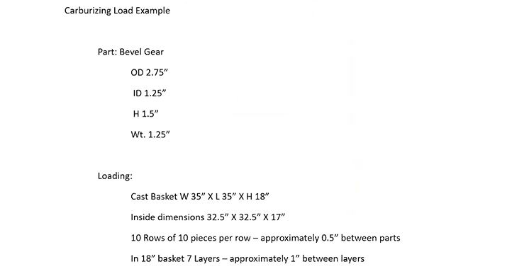
Figure 1: Carburizing Load Example (Source: Erie Steel)
Here we’re just going to make an example:
Pusher Load Description (00:58)
Contact us with
your Reader Feedback!
I’m going to take a fictious gear: it’s 2 ¾ inch in diameter, it’s got an inside diameter of an inch and a quarter, it’s an inch and a half tall, and it weighs 1.25 pounds. For our purposes here, we’re going to put these in a cast basket. For the furnace that we’re going to put them in, the basket size is 36 inches square — so, it’s 36 x 36. The height in this pusher furnace is going to be 24 inches; the inside dimensions of a 36-inch basket (actually it’s a 35-inch basket that sits on a 36-inch tray) is 32 ½ inches.
Michael Mouilleseaux General Manager at Erie Steel, Ltd. Sourced from the author
We’re going to say that this basket is 18 inches tall, so we’re going to get 7 layers of parts so that there’s approximately 1 inch between each layer of parts. This loading scheme gets us 700 pieces in a basket; it gets us 875 pounds net.
So the 36-inch basket that’s 18 inches tall and we’ve got 10 rows of 10 pieces, and we’ve got 7 layers of these things, so we have some room in between them. The reason for that is circulation of atmosphere and quenchant. This is what’s going to constitute the pusher load.
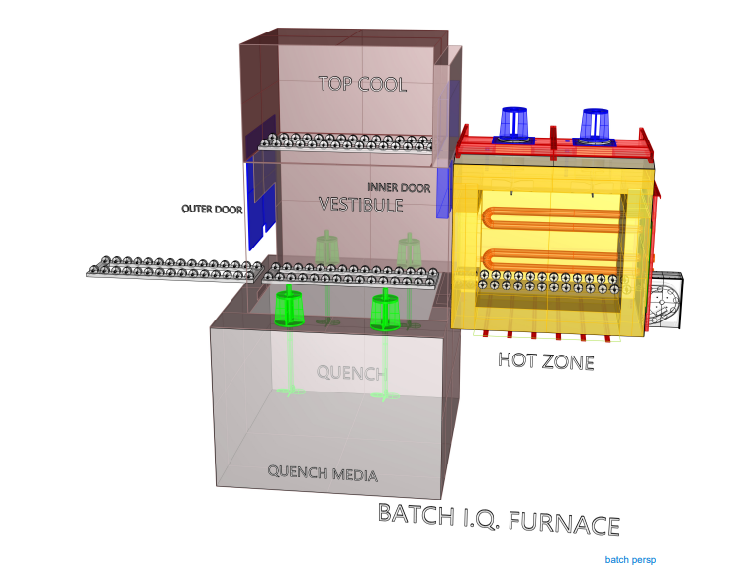
Batch Load Description (03:09)
Now, when we go to the batch load, we’re going to take four of these, because the batch furnace that we’re going to compare this to is going to be 36 inches wide and it’s going to be 72 inches long. We have two baskets on the bottom, 36, and then two of them is 72, and two on top. They’re 18 inches high, so 18 and 18 is 36 — a standard 36 x 72. It’s got 40 inches of height on it. I can take that 36 inches, put it on a 2 ½-inch tray and I can get it in and out of the furnace.
What is this four baskets? 2800 pieces in a load and 3500 pounds. That’s the difference. I’m comparing one basket, 700 pieces and 875 pounds and we’re going to compare that to what we would do if we ran a batch load, which is significantly more. It’s 2800 pieces and 3500 pounds.
What do we want to do with this?
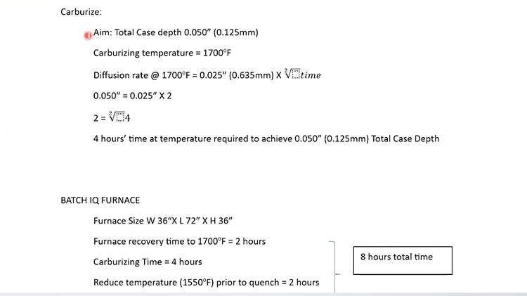
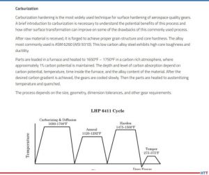
Let’s say that we’re going to carburize this, and we want 50 thousandths case (total case depth of 0/050”). Now, I will show you very soon why we’ve chosen 50 thousandths case. Because at 1700°F (which is what we’re going to carburize at), the diffusion rate is 25 thousandths of an inch times the square root of time.
Now, I can do that math in my head. 25 thousandths times 2 is 50 thousandths. That means we need four hours. So, the part would have to be in the furnace for four hours, at temperature, carburizing, in order to achieve 50 thousandths case.
Figure 2: Batch IQ Carburizing Load (Source: Erie Steel)
Batch Furnace Time (04:59)
Let’s look at the next section. As we said, the furnace is 36 x 72 x 36 and we have 2800 pieces in the load. So, that is 1700°F. We’re going to say that there is 3500 pounds and there is probably another 800 or 900 pounds in fixturing so that’s about 4500 pounds. It’s very conservative; in a 36 x 72 furnace, you could probably get away with running 6,000 pounds. This is just a load that is well within the capability of that.
Furnace recovery is going to take two hours.
Doug Glenn: Meaning, it’s going to take you two hours to get up to temperature.
Mike Mouilleseaux: Until the entirety of the load is at 1700°F, that’s right. Inside, outside, top to bottom.
We’re going to carburize this at four hours, as we described previously; we calculated that and we need four hours to get our 50 thousandths case. Then we’re going to reduce the temperature in the furnace to 1550°F so that we can quench it.
So, we have two hours of furnace recovery, four hours at carburizing, two hours to reduce the temperature and attain a uniform 1550°F. That’s eight hours, and that’s what you would term an 8-hour furnace cycle.
We know that we have 2800 pieces in the load. In eight hours (2800 divided by 8) you’ve got 350 pieces/hour. That’s what the hourly productivity would be in this load.
We won’t talk about “what could we do.” There’s a lot of things that we could do. This is simply an example.
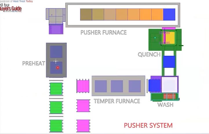
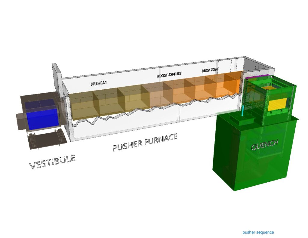
Pusher Furnace Time (07:05)
Now, in the pusher load, as previously described, it’s 36 x 36 and it’s 24 inches high. Now, we know that we have a basket that’s 18 inches high. Again, it’s going to sit on a 2-inch tray, so we’ve got 21 inches of the top of the basket that is going to fit in the furnace; there are going to be no issues with that whatsoever.
The controlling factor is that we want four hours at temperature. In the boost and diffuse, we have four positions. The furnace cycles once per hour.
We get one load size (700 pieces, 875 pounds) every hour. So, in this example (an 8-position, 36-square pusher) this process would yield 700 pieces an hour, and a batch furnace loaded as we described (same exact loading and number of pieces/basket) would yield 350 pieces/hour. In this scenario, the pusher furnace is going to produce twice the number of parts/hour that the batch would.
So, you would say, “Well, let’s just do that.” What you have to understand is that every hour, you are going to produce 700 pieces. If we went back and we looked at that description of what that pusher system looked like, you would see there are 23 positions in that. When I load a load, it’s going to be 23 hours before the first load comes out.
What we’re talking about is whether or not there were 700 pieces and 800 pounds, 23 of those[ET10][BL11] load.
The point would be, you either have to have enough of the same product or enough of similar product that can be processed to the same process to justify using something like this. Because if we want to change the cycle in the furnace. So, can we do that? The answer is absolutely, yes.
The preheat there, that stays at relatively the same temperature. The first zone in the furnace where we’re preheating the load, that temperature can be changed, as can the temperature in the boost diffuse and/or cycle time.
Figure 3: Pusher Furnace System (Source: Erie Steel)
So, in our example, we used an hour. What if you wanted 40 thousandths case and you’re going to be closer to 45 minutes or 50 minutes of time, how would you accomplish that? That can be done.
Typically, commercial heat treaters would come up with a strategy on how to cycle parts in and hold the furnace, or how many empties you would put in the furnace before you would change the furnace cycle.
Obviously, in the last two positions, where you’re reducing temperature, you could change the temperature in either the first two positions, where you’re preheating the load, or you could change the carburizing temperature, because when we’re dropping the temperature, it doesn’t have a material effect upon that.
Typically, in an in-house operation, you would not do that kind of thing, for a couple of reasons, not the least of which would be considering the type of people that you have operating these furnaces. They come in and out from other departments, and this is the kind of thing that you would want someone experientially understanding the instructions that you’ve given them. The furnace operator is not necessarily going to be the one to do it; this may be a pre-established methodology. You want them to execute that. But if you have somebody that is running a grinder and then they’re running a plating line and then they’re coming and working in the heat treat, that would not be the recipe for trying to make these kinds of changes.
As I described to you before, I worked in another life where we had 15 pushers. They were multiple-row pushers. We made 10,000 transfer cases a day. The furnace cycle on every furnace was established on the 1st of January, and on the 31st of December it was still running the same furnace cycle. You never changed what you were doing. The same parts went into the same furnaces and that’s how they were able to achieve the uniform results they were looking for.
Pusher Furnaces and Flexibility (12:45)
So, the longer the pusher furnace is, the less flexible it is.
In this example, you have eight. You know, there are pusher furnaces that have four positions. If you think about it, in a 4-position furnace, you could empty it out pretty quickly and change the cycle.
There are a lot of 6-position pusher furnaces in the commercial heat treating industry; that seems to be a good balance. The number of multiple-row pushers in the commercial industry, they’re fewer and far between. I’m not going to say they’re nonexistent, but enough of the same kind of product to justify that is difficult.
I think the bottom line here is, for companies that are having high variability, low quantity, low volume loads, generally speaking, your batch is going to be good because it’s very flexible, you can change quickly.
However, with a company like the one you were describing where there is low variability and very high volume, pushers are obviously going to make sense. But there is a whole spectrum in between there where you’re going to have to figure out which one makes more sense — whether you’re going to go with a batch or a continuous.
Mike Mouilleseaux: Possibly underappreciated is the aspect of distortion.
In that carburizing example, you’d say, “We have an alloy steel, we’re aiming for 50 thousandths case — what’s the variation within a load?” And I’m going to say that it is going to be less than 5 thousandths, less than 10%. From the top to the bottom, the inside to the outside, it’s going to be less than 5 thousandths. That same process, in the pusher furnace is going to be less than 3 thousandths.
That’s one aspect of the metallurgy. The other aspect is quenching.
Doug Glenn: 5 thousandths versus 3 thousandths — 3 thousandths is much more uniform, right?
Mike Mouilleseaux: Correct.
Doug Glenn: And that’s good because that way the entire load is more consistent (in the continuous unit, let’s say).
Mike Mouilleseaux: That is correct.
Then there is the consistency in quenching. In the batch furnace, you’re quenching 36 inches of the parts. If we had seven layers in the pusher, we have 14 layers of parts in the batch. What are the dynamics involved in that?
We have experience that the ID of a gear (it’s a splined gear) in a batch furnace, we were able to maintain less than 50 microns of distortion. There is a lot involved in that, that’s not for free; there’s a fair amount involved in that and it’s a sophisticated cycle, if you will. That same cycle in a pusher furnace, same case depth, similar quenching strategy, will give you less than half that amount of distortion.
To the heat treater, where we’re talking about the metallurgy of this, you’re going to think 5 thousandths or 3 thousandths is not a big deal.
To the end-user, that reduction in distortion all of a sudden starts paying a number of benefits. The amount of hard finishing that has to be done or honing or hard broaching or something of that nature suddenly becomes far more important.
Doug Glenn: Yes. That adds a lot of money to the total process, if you’ve got to do any of those post heat treat processes.
Mike Mouilleseaux: To a large extent, that is due to the fact that you have a smaller load. If you have a smaller load, you have less opportunity for variation — it’s not that it’s all of a sudden magic.
Doug Glenn: And for the people that don’t understand exactly what that means, think about a single basket that goes into a quench tank and four baskets, arranged two on top and two on bottom. The parts in the middle of that are going to be quenched more slowly because the quench is not hitting it as much.
So, the cooling rates on a stacked load are going to be substantially different than for a single basket, and that’s where distortion can happen.
Mike Mouilleseaux: There are a tremendous number of components that are running batch furnaces successfully. The transportation industry, medical, aerospace, military — are all examples. I’m simply pointing out the fact that there is an opportunity to do something but what we have to keep in mind is — how many of those somethings are there available?
The one thing you would not want to do is try to run four loads in a pusher furnace that could hold 10 because the conditions are not going to be consistent. The front end (the first load) has nothing in front of it so it’s heating at a different rate than the loads in the center, and the last load is cooling at a different rate than the loads that were in the center. That which I just described to you about the potential improvement in distortion, that would be negated in that circumstance.
Doug Glenn: If you’re running a continuous system at full bore and you’re running a batch system at full capacity, especially when you get to the quench, there are a lot of other variables you need to consider in the batch.
This is simply because of the load configuration, and the rates of cooling from the outer parts — top, bottom, sides, as opposed to the ones in the middle. Whereas with a single basket, you still have to worry about the parts on the outside as they’re going to cool quicker than the parts on the inside, but it’s less so, by a significant degree.
Mike Mouilleseaux: Something that I have learned — which is totally counterintuitive to everything that I was educated with and everything that I was ever told— we’d always thought that it was the parts in the top of the load where the oil had gone through and had an opportunity to vaporize and you weren’t getting the same uniform quench—those were the parts that you had the highest distortion.
Counterintuitively, it’s the parts in the bottom of the load that have the greatest degree of distortion. It has very little to do with vaporizing the oil and it has everything to do with laminar flow versus turbulent flow.
Doug Glenn: In the quench tank, is the oil being circulated up through the load?
Mike Mouilleseaux: Yes.
Doug Glenn: So, supposedly, the coolest oil is hitting the bottom first.
Mike Mouilleseaux: Yes.
Thoughts on the Future of Furnace Improvement (22:20)
Doug Glenn: What about the future on these things?
Mike Mouilleseaux: Where do we think this thing is going? Obviously, you’re going to continue to see incremental improvement in furnace hardware: in burners, in controllers, in insulation, in alloys. These things will be more robust; they’re going to last longer. If we looked at a furnace today and we looked at a furnace that was made 50 years ago, and we stood back a hundred yards, almost no one could tell what the difference was, and yet, it would perform demonstrably different. They are far more precise and accurate than ever.
For the process control systems, we’re going to see real-time analysis of process parameters. We don’t have that now. I think that machine learning is going to come into play, to optimize and predict issues and prevent catastrophic things.
In terms of atmosphere usage, if you’re running the same load, and you run it a number of times, the heating rate should be the same, and the amount of gas that you use to carburize that load should be exactly the same. But if you have a problem with atmosphere integrity — you got a door leak, you got a fan leak, or you got a water leak on a bearing — those things are going to change. Now, by the time it gets your attention, you could’ve dealt with that much sooner and prevented other things from happening.
"For the process control systems, we’re going to see real-time analysis of process parameters. We don’t have that now. I think that machine learning is going to come into play, to optimize and predict issues and prevent catastrophic things."
So, did it cause a problem with the part? By the time it causes a problem with the part, it’s really serious. The point is that there is something between when it initiated and when it’s really serious. With the right kind of analysis, that could be prevented. I think that that kind of thing is coming.
Motor outputs, transfer times — I see all of those things being incorporated into a very comprehensive system whereby you’re going to understand what’s happening with the process in real-time. If you make adjustments, you’re going to know why. Then you’re going to know where you need to go and look to fix it.
The other thing I see happening in the future is all about energy and greenhouse gases. Our Department of Energy has an industrial decarbonization roadmap today, and it’s being implemented, and we don’t even know it. One of the targets in this industrial decarburization roadmap is reduction in greenhouse gases: 85% by 2035, net zero by 2050.
So, what does that mean? I’ve listened to the symposiums that they have put on. There are three things that they’re looking for and one is energy efficiency. I’m going to say that we’ve been down that road and we’ve beat that dog already. Are there going to be other opportunities? Sure. It’s these incremental things, like burner efficiency. But there is no low hanging fruit in energy efficiency.
The other thing is going to be innovative use of hydrogen instead of natural gas because the CO₂ footprint of hydrogen is much lower than that of natural gas. If you look at how the majority of hydrogen is generated today, it’s generated from natural gas. How do you strip hydrogen out of there? You heat it up with natural gas or you heat it up with electricity. Hydrogen is four times the cost of natural gas as a heating source.
The other thing that they’re talking about is electrifying. It’s electrify, electrify, electrify. The electricity has to be generated by clean energy. So, does that mean that we run our furnaces when the wind is blowing or the sun is out, or we’re using peaker plants that are run off hydrogen, and the hydrogen is generated when the sun is shining or the wind is blowing, and we’re stripping out the natural gas?
From what I, personally, have seen with these things, these are absolutely noble goals. You could not disagree with them whatsoever. The way that they want to go about accomplishing it, and the timeline that they wish to accomplish that in, is unrealistic.
If you look at how the majority of hydrogen is generated today, it’s generated from natural gas. How do you strip hydrogen out of there? You heat it up with natural gas or you heat it up with electricity. Hydrogen is four times the cost of natural gas as a heating source.
Doug Glenn: Well, Michael, don’t even get me going on this! There are a lot of different things that are going on here but it’s good to hear you say this stuff. I agree with you on a lot of this stuff. They are noble goals; there is absolutely nothing wrong with electrifying.
Now, I do know some people — and even I would probably fall into the camp of one of those guys — that questions the premise behind the whole decarbonization movement. I mean, is CO₂ really not our friend? There’s that whole question. But, even if you grant that, I agree with you that the timeframe in which they’re wanting to do some of these things is, I think, fairly unrealistic.
It’s always good to know the reality of the world, whether you agree with it or not. It’s there, it’s happening, so you’ve got to go in with eyes wide open.
Safety Concerns (29:41)
Mike Mouilleseaux: The safety concerns on these are all very similar. You know, the MTI (Metal Treating Institute) has some pretty good safety courses on these things, and I think there are a lot of people who have taken advantage of that. The fact that it’s been formalized is much better.
When I grew up in this, it was something that you learned empirically, and making a mistake in learning it, although the learning situation is embedded in you, sometimes the cost of that is just too great, so that the probability of being hurt or burnt or causing damage to a facility, is just too great.
There are definitely things that need to be addressed with that, and there are some very basic things that need to be done.
Doug Glenn: Michael, thanks a lot. I appreciate your expertise in all these areas, you are a wealth of knowledge.
Michael Mouilleseaux is general manager atErie Steel LTD. Mike has been at Erie Steel in Toledo, OH since 2006 with previous metallurgical experience at New Process Gear in Syracuse, NY and as the Director of Technology in Marketing at FPM Heat Treating LLC in Elk Grove, IL. Having graduated from the University of Michigan with a degree in Metallurgical Engineering, Mike has proved his expertise in the field of heat treat, co-presenting at the 2019 Heat Treat show and currently serving on the Board of Trustees at the Metal Treating Institute.
Our readers and Heat Treat Radiolisteners will remember a recent episode entitled "Heat Treat Radio #102: Lunch & Learn, Batch IQ Vs. Continuous Pusher, Part 1." Today's Technical Tuesday article is a continuation of this dialog, with Michael Mouilleseaux, a boot-on-the-ground North American heat treat expert from Erie Steel here to answer your questions on the maintenance of batch and continuous pusher furnace systems.
Doug Glenn, Heat TreatToday's publisher,Karen Gantzer, associate publisher/editor-in-chief, join in this Technical Tuesday article.
Stay tuned for a Part 2 continuation of the Lunch and LearnHeat Treat Radio episode, coming to Heat Treat Radio in a couple weeks.
Below, you can watch the video or read from an edited transcript.
Michael Mouilleseaux
General Manager at Erie Steel, Ltd.
Sourced from the author
Introduction to Maintenance
Doug Glenn: We would like to move on to maintenance of the batch furnace and the continuous furnace. What is the cost of maintaining and operating these furnaces?
Michael Mouilleseaux: When they are utilized in a carburizing environment, there is always excess carbon that falls out or precipitates out of the atmosphere, and it ends up as elemental carbon in the bottom of the furnace.
What do you do with that? In furnaces that are using a carburizing environment, the burnout of the furnace is easily the single most important piece of preventative maintenance that you can perform. How is that performed? First, the furnace is vacated; there is no product in the furnace, the temperature is reduced — typically, you want it down around 1500°F or 1550°F — and you introduce room air into the furnace. The room air ignites the carbon. It’s a very primitive operation.
So, what temperature does carbon burn at? It burns at 3000°F.
You need to be very careful. It’s a controlled burn because you can actually damage the furnace through refractory, through the alloy that’s in the furnace, or it can get away. How do you do control it? On one level, you’re just looking at the temperature control. If you have it set at 1550, you’re going to say, “I’m only going to put air as long as the temperature of the furnace does not go up more than 25°F or 50°F.” It’s somewhat dependent upon the piece of equipment and is one of those things that you learn empirically; there is not a hard and fast rule for it.
Then, you can shut off the air. If there is no oxygen, then the source for combustion is taken away and you stop that operation. If you need to do it more rapidly than that, you may need to flood the furnace with nitrogen. Typically, if you have to flood the furnace with nitrogen to do it, you’ve been a little too aggressive in your burnout.
How long do you perform that? The great thing with oxygen probes is that you can utilize your oxygen probe to help you learn when you have burnt out the furnace. You’re not getting an actual carbon atmosphere, but what you do get is a readout from the probe. What you can do is perform the burnout operation until you attain that level and then you know that you’ve done a sufficient job in burning it out. That’s the single most important piece of preventative maintenance that’s done on a furnace used for carburizing.
Doug Glenn: Is that both in batch and in continuous?
Michael Mouilleseaux: Identical, yes.
Doug Glenn: I’ve got a couple other questions about furnace burnouts as someone who’s not a furnace operator. You said that there’s “carbon dropout” in the furnace. I know that in some furnaces, parts of the atmosphere may precipitate onto the coolest part of the furnace. Is that what is happening, or are we talking about carbon powder at the bottom of a furnace?
Michael Mouilleseaux: It is carbon powder, and it becomes more egregious. The powder then begins to accumulate into pebbles, nuggets, and larger size pieces. That’s more problematic. When it is in a powdered form, that is the best.
The question will be: How often do you have to do this? As with everything, the answer is — it depends. It depends on what you’re doing; it depends on how aggressive you are in your carburizing.
In the boost phase, we talked about carburizing at upwards of 1%. As soon as you exceed the saturation level of carbon, you’re going to precipitate out the excess carbon. What is that number? It’s different for every temperature. At 1500°F, it’s .9 or .85; at 1750°F, it’s 1.25. But to attain that, you’re actually putting natural gas into the furnace, and the amount of natural gas that you put into the furnace and its dissociation rate — the rate that it breaks down — can then subsequently be diffused into the parts; all of that comes into play.
With saturation levels of carburizing, there is always some residual carbon that’s in the furnace.
Doug Glenn: You mentioned that carbon burns at around 3,000 degrees. Are you taking the furnace up to that temperature?
The great thing with oxygen probes is that you can utilize your oxygen probe to help you learn when you have burnt out the furnace. You’re not getting an actual carbon atmosphere, but what you do get is a readout from the probe. What you can do is perform the burnout operation until you attain that level and then you know that you’ve done a sufficient job in burning it out. That’s the single most important piece of preventative maintenance that’s done on a furnace used for carburizing
Michael Mouilleseaux: No. The burnout cycle is at 1500 or 1550. You raise that carbon to that level and introduce oxygen, and what you want is a slow burn.
We next think about the systems involved in the furnace. First there is the heating system. In a gas-fired furnace, some critical things to consider are burner recovery, burner adjustment, and the amount of excess air that results in that burner adjustment. That’s a preventative maintenance operation that needs to be performed on a regular basis. It probably doesn’t need to be done daily, but monthly is optimal. If everything is very steady, including the barometric pressure, then you don’t need to do all of those adjustments.
Now, electric furnaces have SCRs that fire the elements, and you have to pay attention to the tuning of those things to make sure that they’re operating at optimum performance. One of the ways that you can do that, in a batch furnace, is if you look at the recovery time.
For example, if you have a load that weighs 4000 lbs. and you put it in the furnace and you know that it takes an hour and a half for the furnace to recover to temperature, but then all of a sudden, it takes an hour and 45 minutes, or an hour and 50 minutes, or two hours, obviously the burners are not producing the same amount of heat. The burners are not pumping the requisite amount of BTUs to achieve that recovery time. Could that be related furnace circulation? Could it be related to the insulation in the furnace? At an extreme, it could. Typically, though, it’s related to burner or SCR tuning.
Those are the kinds of things that are very easy to pay attention to.
"Electric furnaces have SCRs that fire the elements, and you have to pay attention to the tuning of those things to make sure that they’re operating at optimum performance. One of the ways that you can do that, in a batch furnace, is if you look at the recovery time."
Setting up PM Through Controls System
The control schemes in the PLC are typically very robust. So, you can establish a program and the PLC is going to say, “I want to heat it at this rate, I want the carbon potential to be .4%, I want to hold this at two hours at temperature, and then I want to initiate a quenching cycle.” Typically, PLCs are quite robust.
The thing you have to be careful with is obviously not just power outages, but brownouts. Brownouts are when you don’t quite lose all voltage, but you lose some of it. If you don’t have some kind of a filter on the power you can mitigate with, or have an uninterruptable power supply for the PLC, you can damage those things, resulting in some major work on the PLC.
The other part of that is the furnace circulation. We’ve got fans in these furnaces, and we circulate the atmosphere. The primary stages of heating in the furnace are convection, until we get to 1200 degrees. How do we convect the heat? We have the atmosphere in the furnace, the fan circulates, it washes the atmosphere down the radiant tubes, it heats up the atmosphere, the atmosphere comes into contact with the components, and we’re convection-heating the parts.
Once we get to 1200 degrees or more, then the primary method of heating becomes radiant heating. That’s where the radiant tubes are then the primary means of transferring energy. But the fans become very important. Are they balanced? Is the RPM correct? Is the amp reading on the fan? Those are areas to look at.
You have to understand how the furnace operates when it’s healthy — the furnace manufacturer can help you and/or you just learn empirically. For instance, what would it mean if, all of a sudden, I’m drawing much fewer amps on a circulating fan and it’s running very rough? Quite possibly, we’ve lost a fan blade.
Then there is the atmosphere control system. All that we just described is applicable to both continuous and batch furnaces. The furnace needs to be sealed and you want a couple inches of water column pressure — excess pressure — in the furnace relative to atmosphere pressure, since safety is the number one concern.
The atmosphere that we’re talking about in most of these furnaces is endothermic atmosphere. It’s a reducing atmosphere, meaning that it’s combustible. If, of course, we have combustion in a closed vessel, that’s called an explosion.
The reducing atmosphere, in and of itself, is if you look in a furnace that is at anything above 1200 degrees where it’s red, up to 1700–1800 degrees where it’s going to be yellow to white — and there is no flame . . . . People are absolutely amazed when they look in an atmosphere furnace and they see no flame. What you should see is everything in a relative, uniform color. The parts should be a uniform color. If you look at the tubes, they should be a little lighter because the tubes will always be somewhat above the temperature of the parts . . . .
Back to the atmosphere: We want to be sure that the atmosphere stays in the furnace and that we maintain that pressure in the furnace. So, what would be a cause to lower the pressure in the furnace? A door leak or a leak in a fan. It could be, if you have a mechanical handling system, a leak through that system. Those are all places to look.
The PM on that? For maintaining the level of lubrication in the fan bearings, see that they’re cooled so that the outlet temperature of the coolant — be it air or water — should be higher than the inlet temperature; that shows that they’re being cooled.
I can’t tell you an absolute number, but I can say that for the equipment that we have, we have numbers that we’ve developed; we know that if the outlet temperature of the water is 20 degrees higher than it is going in, we’re doing a good job of cooling the bearings.
The door seals in furnaces, typically, are brick on brick. Typically, they use a wedge system to seal the doors in the furnace. But, of necessity, these are wear items. Therefore, in preventative maintenance, you might notice a burnout around a door where you hadn’t had one before. That tells you that atmosphere is leaking out of that door and so a repair is needed in the near future.
An interesting thing about a batch furnace: Most of them only have one door. So, it’s quite easy — you can open the vestibule and, in a maintenance operation, if you gassed up the furnace, you could see.There is always going to be some atmosphere coming around the door because that’s where the atmosphere goes into the vestibule, but it should be at the top; it shouldn’t be around the sides, and it definitely shouldn’t be at the bottom. It should be very consistent.
That’s one of those things that, again, you empirically learn. You look at it — it’s a visual operation to say what you’re doing.
There are two other systems: First, the quench system. We talked about how critical the quench system is. The RPMs of the prop, the amp draw of the motors for the props — those things should be very consistent. I think they should be monitor and data logged. The reason for that is you want to know when you quench a load that the RPMs of those props are what you have set it for. When you introduce a load into the quench, the amp draw is, of necessity, going to increase. That’s because you’ve put something in the path of the quenchant so, in order to maintain that flow, you’ve increased the amount of work that it takes to rotate those props.
That’s the kind of thing that you want to monitor. If the amp draw is changing, that means that there’s something in the quench system. Could it be the bearings? Could it be the motor? Those are some things that you’d need to take a look at and be certain of. Obviously, the props need to be in balance; you don’t want any vibration in them.
Doug Glenn: This is also true on the continuous furnace. You’ve got three or four green props in the batch furnace, and it would be the same in the continuous furnace.
Source: Erie Steel, Ltd
Maintenance of Quenchant
Michael Mouilleseaux: Also, there is the maintenance of the quenchant. I’m of the belief that the quench should be continuously filtered. I’m not a fan of batch filtering. I’ve been doing this long enough that I’ve done that, and it just isn’t successful. Quite possibly there are operations that allow it.
If you’re carburizing, you’re going to have particulate in the quenchant because that same atmosphere precipitation of carbon finds its way into the quench. It’s going to be on the parts, it’s going to be on the trays, it’s going to be dragged in there. So, you have this particulate carbon in the quench and it acts as a catalyst to break down the oil.
One way to extend the life of the oil is to make sure that you’re continuously filtering that out. People say 50 microns or 100 microns or 25 microns. Experientially, I’m going to say that it’s going to be 25 microns. If you have a 100-micron filter, that’s great for getting the pebbles out of the quench or the scale, if that were to be an issue with your customer’s parts, but that’s not sufficient to filter out the particulate that’s going to be of the size that’s going to catalyze the breakdown of your quenchant.
Doug Glenn: I assume that if you’re providing for some sort of continuous filtering of your quench, that’s built into the quench structure. The quench tank is built for that, right, and you’re continually flowing it through this filter?
Michael Mouilleseaux: I’m not going to say that no manufacturers offer sufficient quench filtering, but I am not aware of anyone that offers a quench filtration system that’s sufficient. Most of these things end up being standalone. You want to draw the quenchant from the bottom of the tank in one quarter, you want to put it through a series of filters, and you want to put it back into the furnace at the opposite end of the quench tank.
I can say with certainty, that a batch furnace which has not been filtered well, if you remove the quenchant from the furnace after six months — definitely after 12 months — of using it in daily carburizing, you’re going to take 55-gallon drums of sludge out of the furnace, and the sludge is essentially carbon that’s mixed in with the oil.
For that same furnace, with a sufficient quench filtration system, there will be little pockets in the four corners of the quench tank, but that’s about it.
CQI-9, Nadcap and all of those standards have a requirement for monitoring of quenchant. One of the monitors should be particulate because that lets you know how good a job you’re doing in filtering.
Having done it properly, one can say, “Well, I have to replace my quench oil,” — fill in the blank — “once a year, once every six months, once every two years.” Properly maintained and filtered, the quenchant does not have to be replaced very often.
You’re going to drag out a little oil on every load. You want to let the load drip so that you’re not taking that precious quench oil and just putting it in the wash and washing it off. But in a batch furnace, you could have a couple hundred gallons a month to four hundred gallons, depending on the size of the furnace, of add-back that you’re putting in there. Is that sufficient to maintain all of the additives that are in the quenchant? Is that something that you need to monitor? Typically, the manufacturer can do that for you. You get monitoring and you see what the quench speed is, what is the viscosity, flash – all of those important pieces of information.
Now, it doesn’t come for free. A filtration system is costly, and the filters are costly. A year’s worth of quenchant is five years’ worth of filters. In my mind, that’s a good tradeoff.
Karen Gantzer: So, Michael, when the process is filtering the quench, does this happen during production downtime?
Karen Gantzer
Associate Publisher/ Editor in Chief
Heat Treat Today
Michael Mouilleseaux: No, it’s done continuously. Even when the furnace is not running on the weekend, you’re still filtering the oil. You’re going to be taking 20-50 gallons out of the quench tank but you’re putting it right back in. It just passes through filters.
Some people have utilized centrifuges. It’s a very successful way of filtering out carbon particles in oil. The caveat on that is you don’t want the oil above 140 degrees. If you get the oil above 140 degrees and for every 20 degrees you go up, you start doubling the oxidation rate of the oil.
In high-temperature oil, we do a fair amount of modified marquenching. We do it in closed canisters. The seals must be temperature-tolerant, but it is very successful.
The last part is going to be the quench heating and cooling. Typically, at the first part of the week when you’re starting up the furnace or if you’re going from operation A to operation B and it requires a higher temperature quenchant, you’re going to use either gas or electric elements that are going to heat it. Those things need to be monitored so that they’re available when you need them. The last thing that you want to do is start out the week and find out that the quench heaters don’t work; then, you’re trying to find a couple of dummy loads that you can heat up to put into the quench to heat up the quenchant before proceeding with operations.
Then, of great, importance is quench cooling. In petroleum-based quenchants, you’ve got a flashpoint of 400 degrees plus or minus — could be 350, could be 450, depending upon the quenchant that you’re using. You don’t want the temperature of that oil to approach that flashpoint. You do that by using a quench-cooling system. It’s a big radiator. You’ve got a pump, and you set it when you want the pump to go on. You pump the oil out to the quench coolant, and when it comes back, once you’ve attained what your temperature is, then you stop.
Doug Glenn: I’ve got a couple quick questions on this. First, is the quench heater an immersion tube?
Michael Mouilleseaux: Yes. Gas-fired tubes and gas-fired units are very small u-tubes that go into the quench tank. Electrical units have got elements that are tolerant to that.
Doug Glenn: Typically, you’re using those because you’re actually using the quenchant and always putting hot things into it, so once the quench fluid is up to temperature, it’s not a problem. You’re using that quench heater just to get the thing up to temperature. So after that, most of the time, you’re using the cooler to keep it cool, correct?
Michael Mouilleseaux: Absolutely. That’s a control scheme. The last thing that you want to do is set the quench heater so that it’s within five degrees of setpoint and set the quench cooling so that it’s within five degrees of setpoint — then, the temperature just sits there, with heating and cooling fighting each other. You’re heating and cooling oil unnecessarily. You want to give yourself some bandwidth on that.
Material Handling System
Last is going to be the material handling system. In the batch furnace, many have what we call a “rear handler.” We saw the cart and it would push the load into the vestibule, the inner door would open, and it would push the load into the furnace. It’s always preferable to push hot loads, not to pull on them. The reason is that the base trays are alloy and the compressive strength is much higher than the tensile strength is. If you’re pulling on loads, you’re going to break trays.
Once the load is in the furnace, you would have a rear handler so when the cycle is terminated and the inner door opens, you would have a mechanism — it may have a flat bar that’s half the width of the tray — that actually pushes the load into the quench vestibule.
There it’s pushed by the charge car and the inner door is open. That same handler, from the charge car, pushes it into the furnace. Now, when the cycle is terminated, there is a handler in the rear of the furnace that pushes it into the vestibule for quenching.
The exception is right here: When it’s taken out of the vestibule, typically the charge car goes in and grabs it and pulls it out. But, at that point, you’re at 100 or 200 degrees so, at that temperature, you have no material effect upon the strength of the alloy.
Doug Glenn: Okay, the motion it took it from the tray on the left inside is going to push it in and then the next step it’s also going to push it into this “hot zone,” correct?
Michael Mouilleseaux: Yes.
Doug Glenn: But what you’re saying is, when it’s coming out of the hot zone, there’s probably a mechanism on the far righthand side of the hot zone that’s going to push it back. Nothing is going in to pull it out because it’s hot.
Michael Mouilleseaux: Extended reach cars put the load into the vestibule and then put it into the hot zone.
There are some rear handlers that, rather than being a simple push function, have a dog mechanism that allows them to go and get the load in the vestibule and pull it into the furnace. Personally, I am not a fan of that; I like the extended reach car because when you’re pushing something, it is very easy to determine if you’ve put it in the right location. If you grab a load and pull it, you could lose the attachment on that load and then it’s not put exactly where you want it to be.
You can put amp meters on these things so that the amount of force that the motors require to pull in or push out a load. The one thing you need to be cognizant of is that it’s going to take more power — a higher amp draw — to push a 4000-pound load than it is a 2000-pound load. Once you understand what that is, you can monitor these furnaces and then they start making sense to you.
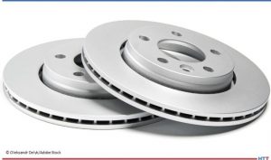
Are your brake rotors heat treated? Travel back in time to discover how ferritic nitrocarburizing (FNC) became the heat treatment of choice for automakers’ brake rotors and why the tip-up furnace forever altered the production process for this part.
This Technical Tuesday article is drawn from Heat Treat Today's February Air & Atmosphere Furnace Systems print edition.If you have any information of your own about heat treating brake rotors, our editors would be interested in sharing it online at www.heattreattoday.com. Email Bethany Leone at bethany@heattreattoday.com with your own ideas!
The Problem: Brake Rotor Corrosion
Michael Mouilleseaux General Manager at Erie Steel, Ltd. Sourced from the author
In the early 2000s, corrosion was one of the top three issues that U.S. automotive manufacturers found negatively affected the perception of the quality of their cars. Brake rotors are made of cast iron. These components sit out in the elements, and in places like the U.S. Midwest where salt is often used on the roads, unprotected steel or iron will corrode or rust. Even on the coast, there is salt water in the air.
Contact us with your Reader Feedback!
What does rusting cause? The rotor rusts, and first, the cosmetics are negatively affected (i.e., rusty appearance). But more importantly, the first time you step on the brakes, it squeals like a pig, the vehicle shudders, and the driver feels pulsing in the pedal. He’ll also feel it in the steering wheel because the amount of rust coating one area is different from the amount of rust that’s on another. So, these brand new, forty- to seventy-thousand-dollar cars have orange rust over the brake rotor and a shaky drive. . . it’s not a good look!
Now, this is just a superficial coating of rust that will eventually abrade away; the rotor will look alright, the vehicle will stop better, and it won’t squeal. However, since the rust on the rotor wears off unevenly, the car may never have smooth braking.
A Move to FNC
In the early 2000s, all the big players were looking to FNC (ferritic nitrocarburizing) as a solution to corrosion, including Bosch Braking Systems, Ford, General Motors, Akebono, and the truck manufacturers. FNC was becoming popular since the process adds a metallurgical layer — called the “white layer” or “compound zone” — to the part, providing corrosion resistance and the bonus of improving wear.
Source: Oleksandr Delyk/Adobe Stock
To the OEMs, the benefits were perceived as:
The corrosion issue had an answer.
The life of the rotor doubled from roughly 40,000 to 80,000 miles. Although that meant half as many aftermarket brake jobs compared to before, consumers perceived it as a real advantage.
The rotors generated less dust. Brakes generate dust particles as the result of abrasion of the pads and the rotors. This particulate dust has been identified as both an environmental and a health concern. Now, flash forward to 2022: Electric vehicles are largely displacing the need to control emissions from ICE (internal combustion engine) vehicles. So, the new European standard on vehicle emissions implemented a requirement to control this dust that is harmful to the environment and which EV and traditional brake systems can emit.
But there were certain technical and practical challenges that automotive manufacturers faced when trying to implement this process at scale.
#1 Distortion. Brake rotors may distort during FNC. Since rotors are (gray iron) castings, the process temperature for FNC may stress relieve the rotor, causing it to change shape or distort, rendering it unusable as a disc brake rotor. It was determined that if the rotor castings were stress relieved prior to machining and FNC, the distortion issue was rendered moot.
#2 Loss of Necessary Friction. FNC gives the white layer on the surface of a part with a diffusion zone underneath. The compound zone has a very low coefficient of friction, which means excellent wear properties. However, manufacturers want friction between the rotor and the brake pads to slow the car down. Reducing the friction on the rotors extends the braking distance of the car.
". . .[M]anufacturers want friction between the rotor and the brake pads to slow the car down." Source: Unsplash.com/Craig MorolfLet me illustrate this: I ferritic nitrocarburized a set of brake discs for Bosch Braking Systems, which eventually went to Germany and then on a vehicle. The customer absolutely loved the corrosion resistance, but when it was time for the downhill brake test, the car went straight through an instrument house because the brakes couldn’t stop the car! Lesson: For rotors treated with FNC, the brake pads need to be made from a different frictional material!
#3 Cost. Overcoming the technical issues is simple. Stress relieving the casting at FNC temperatures before machining it would help the parts machine better and would eliminate distortion. Modifying the FNC process could reduce the depth of the white layer and, paired with the correct friction material, the acceptable braking capabilities were restored. Yet these additional steps presented a new challenge: higher costs.
The practical constraints of FNC in conventional batch or pit furnaces strained efforts to be cost-effective. The load (size) capacity of the conventional equipment, in conjunction with the time constraints of the FNC process presented a dilemma, as the OEMs’ benchmark was about one dollar per rotor.
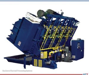
Here Comes the Tip-Up
With traditional furnaces for FNC, there was just no way to reach the economics that were necessary for it. A bigger pit furnace might be the way to go, but they really weren’t big enough. So, here comes the tip-up.
Traditionally, a tip-up furnace has been used for processes with just air, no atmosphere. With direct fired burners, the furnace is used for tempering, stress relieving, annealing, and normalizing. Everything loads into the box, gets fired, and unloads, similar to a car-bottom furnace. With the appropriate external handling systems parts could be retrieved from the furnace and then quenched. This additional process increased the usefulness of the equipment and allowed for the processing of tubes, bars, big castings. . . big forgings for the oil industry and the like.
The question of how to heat treat brake rotors on a large scale still needed to be answered. It required a large, tightly sealed furnace with atmospheric integrity for excellent temperature uniformity. In ferritic nitrocarburizing, the processing range is about 950°F to 1050°F. It is well known that properties vary significantly across the temperature range. And they needed to be optimized to create the appropriate frictional properties for the rotors.
So, the answer was: Let’s make a tip-up furnace that can be sealed for atmospheric integrity, has the appropriate temperature uniformity, and can circulate gas evenly. A lot of this would have to be iterative — create, test, compare, repeat.
Tip-up furnace from Gasbarre Thermal Processing Systems Source: Gasbarre Thermal Processing Systems
The development of the perfect tip-up was essentially the work of one furnace manufacturer and one heat treater who together changed the industry.
American Knowhow Makes the Perfect Tip-Up
In the early 2000s, heat treaters worked with OEMs to develop a cost-efficient process in a tip-up. Manufacturers and service providers tested different methods, including atmosphere FNC and salt bath FNC.
By 2009, the perfect atmosphere furnace was complete and high volume brake rotors began to be processed for General Motors. The furnace manufacturer was JL Becker, Co., acquired by Gasbarre in 2011. The commercial heat treater was Woodworth, Inc., located in Flint, MI. Together, they spent a lot of time and money looking into FNC and figuring out how to make it work in a tip-up furnace.
General Motors was the first one to get on board, utilizing the FNC processed rotors on their pickup trucks and big SUVs, like the Escalade and Tahoe. Ford was not far behind using it on their F150 pickup truck. I was shocked the first time I saw the commercial: a Silverado pickup truck, out in the snow, and the speaker saying, “We now have an 80,000-mile brake system because of a heat treating process called FNC!”
It’s a great story of American knowhow and a collaborative effort between someone who saw a need and someone else who saw the way. To this day, if you want to get a replacement set of brake rotors for your car, go to a place like AutoZone; they will tell you that the difference in cost between the OEM parts and an off-brand is the fact that the off-brand is not heat treated.
About the author: Michael Mouilleseaux has been at Erie Steel, Ltd. in Toledo, OH, since 2006 with previous metallurgical experience at New Process Gear in Syracuse, NY, and as the Director of Technology in Marketing at FPM Heat Treating LLC in Elk Grove, IL. Having graduated from the University of Michigan with a degree in Metallurgical Engineering, Michael has proved his expertise in the fi eld of heat treat, co-presenting at the Heat Treat 2019 show and currently serving on the Board of Trustees at the Metal Treating Institute.
Get ready to watch, listen, and learn about the three most underrated heat treat processes in today’s episode. This conversation marks the continuation of Lunch & Learn, aHeat Treat Radio podcast series where an expert in the industry breaks down a heat treat fundamental with Doug Glenn, publisher of Heat Treat Today and host of the podcast, and the Heat Treat Today team.
Below, you can watch the video, listen to the podcast by clicking on the audio play button, or read an edited transcript.
The following transcript has been edited for your reading enjoyment.
Doug Glenn: There are some underdog heat treat processes out here. I’d like to get to three today. What do you think is number one?
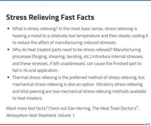
Michael Mouilleseaux: Let’s start with stress relieving. All ferrous materials, all steels, during the course of manufacturing or processing, have some residual stress that is left in them. A common thought about stress relieving is you have a weldment, and you stress relieve it so that the weldment stays.
Contact us with your Reader Feedback!
There is a mechanical action in the material during any cold working operation (cold forging, stamping, fine planking, etc.) because it's done at ambient temperature. Those all impart stress on the part.
Machining, turning, grinding. . . all of those things impart stress into a part. How is that relieved? It can be done thermally, or it can also be done mechanically. Thermally is the most common of them.
What I would like to talk about is not so much stress relieving weldments, it is stress relieving manufactured components. If you’re going to have a comprehensive analysis of the heat treat operation that needs to be performed on a manufactured component, a gear, a shaft, something of that nature, they need to take into consideration what are the prior existing stresses in the part. Then what effect is that going to have on the part?
Many times during the course of my career, I’ve had a customer come to me and say, “The part I gave you was correct, and you’ve given it back to me and then fill-in-the-blank. It’s warped, it’s changed size, it’s shrunk, all of those things.” What have you done in your heat-treating process? You have to back up all the way to the beginning of how this part was manufactured and deal with all of those component steps in order to answer that question properly.
Stress relieving is one of the answers. It’s not the answer. It’s not the only answer, but it is one of them that has to be considered.
"Stress Relieving Tips from Heat TreatToday"
Doug Glenn: For those of us who might not know what a “stress” is in a part, can you simply explain? For example: a coat hanger. If I bend it, is that inducing stress? Is that what’s causing stress? What makes stress in a part?
Michael Mouilleseaux: You’ve cold-worked the part. In the cold working, you’ve passed the yield strength. You’ve bent it, and it’s not going to snap back. You’ve cold-worked it enough that you’ve actually got plastic deformation, and there is stress.
Doug Glenn: That’s one way we get stress. That’s the mechanical way of getting stress.
Michael Mouilleseaux: Right. Now, consider stamping. Even though a stamping is flat (because the die has come down in the perimeter of that and maybe internal holes and things), where you’ve sheared the material, you’ve imparted stress there.
If you harden it or case harden it or whatever you might do with that stamping, you have to take into consideration how much stress is there. If I don’t relieve it, is it going to do that at some point in the part’s future that’s going to be detrimental to the part?
Doug Glenn: When you get a stress in a part, that’s the area that’s a weak spot, right? It potentially could break before other parts?
Michael Mouilleseaux: At the absolute extreme, that could happen, yes. More often than not, what you have is an area that’s been cold worked, and it’s been deformed. When it stresses, it’s going to somewhat relieve itself. It may not relieve itself 100% all the way, but it will somewhat relieve itself. Whatever shape of form you’ve put that part into; it’s not going to hold that form forever.
Alyssa Bootsma: You mentioned that stress relieving is not the only way to alleviate the problems. What would be some alternatives to stress relieving?
Michael Mouilleseaux: Thermal stress relieving is, by far, the most common. There is a process that’s called vibratory stress relieving. In order to relieve the stresses in a part, you have to impart some energy in it. Something between 800 and 1200 Fahrenheit is typically used in stress relieving. That thermal energy goes into the part and relieves the stresses.
You could also do that mechanically by a high frequency vibration. It’s not as common. I believe that it’s actually a propriety process, if not patented. It would be for something that you did not want to subject to 800-1000 degrees Fahrenheit because that doesn’t come for free. Obviously, in a ferrous material at that temperature, you’re going to have some oxide forming on the part. You may or may not be able to utilize the part in its final function with that oxide on it.
Those are typically the two ways to do it. Can it occur naturally over time? Yes, but none of us have that kind of time.
Alyssa Bootsma: You did mention how it doesn’t necessarily mean that it’s more likely to break if that part is not relieved, but what parts would suffer the most if this process was done incorrectly?
Michael Mouilleseaux: Probably weldments. The detrimental effects of not having stress relieved of weldment would be the most significant. In welding there is a whole range of temperatures proximate to the weld — everything from room temperature to maybe 3000 degrees. That whole range of things changes the structure of the steel.
Leaving it in that condition makes it susceptible to any number of things — embrittlement, accelerated corrosion, and others. There is every reason to stress relieve something like that and almost no reason not to.
Doug Glenn: That’s weldment. Do they do a stress relieve after a braze as well, or is that not as common?
Michael Mouilleseaux: Typically not. The reason for that is, in brazing, the entire assembly is brought up to the same temperature. Then it’s cooled at the same rate.
Bethany Leone: I have two brief questions: 1. How long does stress relieving typically take? 2. Would we see the effects of incorrect stress relieving, or failure to, once something goes to quench?
Michael Mouilleseaux: The first question — would you necessarily see a failure? Those would be extremes. I’m more familiar with stress relieving fabricated components that are machined. Take a gear. They forge a blank and maybe machine out the center of the gear, machine the exterior of the gear, cut the teeth in a shaping operation (a hobbing operation or skiving or other ways of generating teeth).
"You have this part, and it needs to be heat treated. To assume that all of those machining operations would have no effect upon that whatsoever is not a good thought."
Then comes a comprehensive program of evaluating how best to heat treat a part. It doesn’t matter if it’s out of a medium carbon alloy steel or it’s a low alloy steel and we’re going to carburize it, what’s critical is that it’s going to get heated. The material is going to transform into austenite and cool rapidly or quench it. That’s what’s going to cause the hardening operation on the part.
In doing that, there are going to be changes in size. In hardening a part, you get a volumetric expansion. Thin sections are not going to expand as much as larger sections. A misnomer is, “You shrunk the hole.” You haven’t shrunk the hole! The material around the hole has expanded, the exterior portion of that area has increased, and the interior portion of that has decreased.
If you have a spline in that hole, now you’re on for something else because their teeth form in that spline. If it’s in a long section, then how uniform it’s been hardened has to do with whether or not it goes out of round or their taper. There are any number of things there. Those are all critical to the operation of this gear.
But what we have to take into consideration is the broaching operation. We drill a hole, and we put a broach bar through it and cut all of these teeth. All of that has imparted stress in the part.
One of the preliminary things that needs to be done is you stress relieve the part and give it back to the manufacturer. They measure it and say, “Oh, oh, it changed!” That change is not something the heat treater can do anything about. That’s the physics of what happens when you work-harden a part. This all has to be taken into consideration and addressed before we talk about what’s the heat treat distortion.
Bethany Leone: And the other question I had: How long does it take to stress relieve?
Michael Mouilleseaux: Typically, if it’s held at an hour or two at temperature, it’s thought that 1000 degrees for an hour at temperature will relieve most stresses.
Now, in a component part, we’re going to go higher in temperature. Although we’re not going to go high enough to austenitize the part, we’re going to go high enough in temperature that we know we’re going to relieve it.
Michael Mouilleseaux: They’re cousins. Stress relieving, the implication is that you are doing that simply to relieve prior existing stresses. In annealing, the implication is that you are going to reduce the hardness of the microstructure for the purposes of machining or forming. In annealing, there’s subcritical and supercritical and a hundred different flavors of that.
Doug Glenn: I’m trying to get a sense of what percentage of heat treating is stress relieving. Is it super popular? It seems to me it would be very common.
Michael Mouilleseaux: Interestingly enough, I’m going to say that the majority of the gearing product that we do, we incorporate a stress relief in the initial stages of heat treating. By putting the part in and raising the temperature to a stress relieving temperature and then taking it up into the austenitizing temperature, you’re not shocking the part. You’re not just taking it from room temperature to carburizing temperature or hardening temperature, and thereby you’re reducing the thermal stresses. So, you’re not imparting any more.
Doug Glenn: Stress relieving may often be done as a part of another process?
Michael Mouilleseaux: It can be, definitely.
Doug Glenn: Let’s move on to the second forgotten heat treatment.
Michael Mouilleseaux: I don’t know about forgotten. I’m going to say that it’s getting short shrift, and that is conventional atmosphere carburizing. What’s sexy in heat treating? It’s low pressure carburizing and gas quenching. It’s growing very rapidly and it’s being used in a lot of applications.
We’re subject to the same ills that Mark Twain identified years ago, and that is, “To a man with a hammer, every problem looks like a nail.” Low pressure carburizing and gas quenching, they can save every distortion issue that’s ever been known to man in heat treating, and they don’t. They are other tools in the box, applicable to a lot of application. They are great processes, very targeted and specific. You know, sometimes you need a screwdriver instead of a hammer.
Conventional carburizing: It’s been around for a hundred years. What’s different today than what it ever was? Certainly it has everything to do with the control systems that are being used to control it. It’s eminently more controllable now than it has ever been. It is a precision operation, and it has many applications. By the way, it’s far more cost effective than carburizing would be. In vacuum carburizing, the cost is multiple; is it two, three or four times more expensive? It depends on how you calculate cost of capital and all of those things. But it’s a multiple, more expensive than conventional carburizing.
Doug Glenn: To do vacuum carburizing?
Michael Mouilleseaux: To do vacuum carburizing, yes. Should it be used in every application? I’m going to say no. Are there definite applications? Definitely.
Doug Glenn: Conventional carburizing, atmosphere carburizing is another area largely forgotten. I know it’s quite popular, but it’s not getting a lot of discussion these days.
Michael Mouilleseaux: Right. Any time there is an issue with a carburized part, everyone knows to ask the question, “Why don’t you vacuum carburize it?” The answer to that is, “Let’s solve the problem before we decide what it is that we need to do.”
Karen Gantzer: Mike: At a very basic level, can you explain why do heat treaters use endothermic gas?
Michael Mouilleseaux: In atmosphere carburizing, we need a method of conveying carbon to the part so that we can enrich it; that’s what carburizing is. The carburizing portion of the atmosphere in endothermic gas is carbon monoxide. Carbon monoxide — that’s the reaction at the surface of the part — the carbon diffuses into the part. That’s how you generate a case in the part.
It’s a relatively inexpensive form of carburizing. You use natural gas and air in what we call a “generator”, and that’s how endothermic gas is generated. Then, it’s put into the furnace. There’s almost no air in a furnace. People think you’re going to look in a furnace, and you’re going to see flame. You never do because the amount of oxygen in the furnace is measured in parts per million. You put additional natural gas to boost the carburizing potential of the atmosphere, and that’s what allows you to diffuse carbon into the part. That is the case hardening process.
Doug Glenn: Conventional carburizing is done in a protective atmosphere, typically as an endothermic atmosphere which is rich in carbon monoxide.
Michael Mouilleseaux: Yes.
Doug Glenn: A lot of times we’re worried about oxygen in the process because of potential oxidation. Why is it that we use a gas that has oxygen in it to infuse carbon? I know it’s got carbon, but it’s also one C and one O, right? Don’t we run into problems of potential oxidation?
"Comparative Study of Carburizing vs. Induction Hardening of Gears"
Michael Mouilleseaux: In endothermic gas there is hydrogen, nitrogen and carbon monoxide, and there are fractional percentages of carbon dioxide and some other things. The hydrogen is what scrubs the part; that’s what kind of takes care of all of the excess oxygen. The nitrogen is just a carrier portion of it, and the carbon monoxide is what is the active ingredient, if you will, in the carburizing process.
The carbon diffuses into the part. If there is an oxygen, it’s going to combine with the hydrogen. Preferentially, you’re not going to have any free oxygen in the furnace, but you can have a little water vapor. One of the ways of measuring the carbon potential in the furnace is a dewpoint meter. The dewpoint meter is measuring the temperature at which the gas precipitates out, and that’s a monitor or a measure of the carbon potential.
Doug Glenn: A dewpoint analyzer helps you know what the carbon potential is.
Michael Mouilleseaux: Yes. It’s not as good as an oxygen analyzer.
Doug Glenn: An oxygen probe.
Michael Mouilleseaux: The oxygen probe is in the furnace, measuring constantly. You get a picture; you have continuous information. It’s not that there aren’t continuous dewpoint analyzers, but you have to take a sample from the furnace. It has to be taken to an analyzer wherein it is then tested. Best case scenario is you have both of them and you compare the two of them. That gives you a really great picture of what the atmosphere conditions are in the furnace.
Alyssa Bootsma: For a bit of background knowledge: What is the difference between endothermic gas and exothermic gas?
Michael Mouilleseaux: Endothermic gas has 40% hydrogen and 20% carbon monoxide. 60% of it is what you would call a reducing atmosphere. The way that you make endothermic atmosphere is 2.7 parts of natural gas and one part of air. You heat it up to 1900 degrees, and it’s put through a nickel catalyst. You strip off the hydrogens. The gas dissociates, and that’s what results.
Exothermic gas is six parts of air in one part of natural gas. You only have 10 or 15% hydrogen. Although it’s not an oxidizing atmosphere, it’s very mildly reducing.
It can be used in annealing, clean annealing. If you’re annealing at 12-1300 degrees or more or in that ballpark, that kind of an atmosphere is going to keep the work clean. If you did it in air, it would scale.
Bethany Leone: Is there an industry (automotive, aerospace, energy) that it would be most helpful for those parts to be typically atmosphere carburized, and/or is it just generally helpful for all types of industries?
Michael Mouilleseaux: First of all, the transportation industry is the lion’s share of heat treating — automotive, truck, aircraft. Atmosphere carburizing is extremely popular and commonplace in those industries.
If we said that we were going to have a seminar and I’m going to talk about atmosphere carburizing. Somebody else is going to talk about low pressure carburizing in a vacuum furnace. Everybody’s going to go over to the other room. Folks feel they already know what this is all about, and they know what all the problems are. They think that the vacuum carburizing is going to solve all of them.
When you work with the proper kinds of controls, the proper kinds of furnace conditions, the right way of fixturing parts and cleaning them ahead of time, you can have extremely consistent results. You can have extremely clean parts, and you can have very good performance from these things.
What the Europeans call “serial production”: we run millions of gears per year, and we have very consistent case steps in hardnesses as a result of good practice. All of these things need to be monitored and controlled and taken care of. But the results are also very consistent and very predictable.
Doug Glenn: Interesting. And it’s more cost-effective, I’m guessing. Conventional atmosphere carburizing, on a per part basis, is going to be substantially less expensive.
Michael Mouilleseaux: We’ve looked at it. Is it two times, is it three times, is it four times more expensive to vacuum carburize a part? The answer is yes. The question is, does that component justify that? There are any number of them where it does.
Doug Glenn: Where it does justify it?
Michael Mouilleseaux: Yes, absolutely.
Doug Glenn: Let’s go on to #3, the third underdog in heat treating.
Michael Mouilleseaux: Number three is marquenching. Marquenching, martempering, and hot oil quenching are in the family that describes this process.
Martempering is different than just quenching in oil, quenching in regular fast oil. Regular oil is going to be 100 vis, and it’s going to be from 90 degrees to 150 degrees. All kinds of low hardenability, or parts that don’t have a lot of adherent alloy in them, you utilize that so that they can be fully hardened. But components that are distortion-critical, quenched in that manner in regular oil, there is going to be a high degree of distortion. How is that addressed? It’s addressed in marquenching.
Let’s take an example of a carburized gear. A carburized case is heated to 16-1700 degrees and carburized. Best practice would say that I’m going to reduce the temperature before I quench it, and then I’m going to quench it in oil. Do I understand that: I have to have loading that spaces the part; and the parts need to be fixtured in such a way that, physically, they don’t impede on each other; and I get full flow of oil, and all of those things? The answer is yes, yes, and yes.
The martensite starts to form in the case at, let’s say, 450 and it’s plus or minus 25 or 30 degrees or so. Take that part and put it into the range where the martensite starts to form, and hold it at that temperature and let the entire part cool down to that 450 degrees where the martensite is starting to form. Then we remove the part from the furnace and allow it to cool in air to room temperature. At that point, the cooling rate is much lower than it it’s going to be where you’re conducting that in a liquid medium. Because of that, the stresses are going to be less, the distortion is going to be less. That is a strategy for reducing distortion.
You ask, “Why do you need to do that.?” Again, the man with the hammer: I’m going to gas quench this part because I have the opportunity to gas quench it, and the gas quenching doesn’t come for free. The shadowing effects of a gas flow has to be taken into consideration, orientation of the parts. There are a number of things that need to be taken into consideration.[blocktext align="left"]There are a number of applications where in marquenching a part, the distortion can be controlled. We process a lot of gears, and we maintain 20/30 microns of total distortion in ID bores on gears. It is a viable way of controlling distortion.[/blocktext]
Doug Glenn: We say marquenching.
Mike Mouilleseaux: Or martempering or hot oil quenching.
Doug Glenn: The “mar” part of that comes from martensite? I want have you explain what exactly martensite is. But is that where it comes from?
Mike Mouilleseaux: Yes. We’re getting right into the start of the martensite transformation.
Doug Glenn: There are different microstructures in metals. Austenite is pretty much the highest temperature, and it’s where the molecules are almost “free floating.” They’re not liquid, but they can move around. (This is very layman’s terms.) That’s austenite.
What causes distortion is when you’re cooling from austenite down to the point where that thing is, kind of, locked in; that can cause distortion in there because the molecules are still free to move. Some areas cool faster than others, and when you have that, you can get twists and turns or bulges. Once it gets down to the martensite temperature, that’s when things are, locked in. Is that fair?
Michael Mouilleseaux: The other thing that happens is you’re going from a cubic structure to a tetragonal structure. You’re asking, “Why are we there?” That’s where the expansion comes. The close-packed tetragonal structure takes up more volume than the austenitic or cubic structure. That’s where the volumetric expansion takes place.
Doug Glenn: At a higher temperature, the molecules are arranged in such a way that they take up more space; there’s more space between them.
In the cooling process with marquenching, if you bring it down just to the point where it’s, what Mike referred to as, the ‘martensite start temperature,’ that’s the temperature where things are just locking in. But it’s not so drastic that you’re dropping way down in temperature so that there are larger temperature differentials and things are really starting to get torqued out of contortion because of the difference in the cooling rates in the part.
Michael Mouilleseaux: The other part of that is that the formation of martensite is not time dependent. It’s not like you would have to hold it at 400 degrees for a longer period of time than you would at 200 degrees to get martensite. At 400 degrees, you’ve got some percentage of transformation. Say, it’s 30%. The transformation is temperature dependent. Because it’s temperature dependent, you can take it out and slow down the cooling rate. Then, as the transformation takes place, there is less stress, and if there’s less stress, then there is less distortion.
Again, it’s typically going to be distortion-sensitive parts.
The simplest geometric shape is a sphere. There aren’t any changes in section size in a sphere. It can be rotated, and you’ve got the same section size. You don’t have the kind of thing where one area is cooling more rapidly than another.
A major source of distortion is varying mass. Like a hole in a block: one portion of the block is two inches wide, and another portion is an inch wide. To think that that hole is going to stay straight all by itself, that won’t happen because there’s more mass around one end. By marquenching it and slowing down the transformation, you’re giving yourself an opportunity to reduce the amount of stress that’s generated. It’s the volumetric expansion in the thicker section than in the thinner section. Your opportunity to maintain that hole so that it stays round and it stays straight is much better. Otherwise, the thin section is going to completely transform before the thicker section does.
Doug Glenn: Transform to martensite or whatever, yes.
Michael Mouilleseaux: The extreme case in that is if that happens rapidly enough, and there’s a large enough differential in section size, the part cracks.
Doug Glenn: That’s the nightmare for the heat treater.
Guest Michael Mouilleseaux with the Heat TreatToday team
Bethany Leone: Are there any instances where it’s definite that another way to manage distortion would be better than marquenching?
Michael Mouilleseaux: Sure. Again, what’s currently sexy in this industry is gas quenching things. I’m going to say that cylindrical parts that have a thin wall, when properly gas quenched, will give you better distortion control, better size control than it would if you’d quench them in a liquid medium such as oil. We don’t want to forget that marquenching can be performed in salt, as well.
If we were going to talk about a fourth one, it might be salt quenching because that’s one of those things that’s not commonly utilized. There is some real opportunity with it.
Doug Glenn: Mike, thanks for ‘dumbing this down’ for us. We appreciate it! It’s sometimes a struggle to state things simply, but you did a great job.
Are there any closing thoughts you’d like to leave with us regarding the nearly-forgotten, popular heat treat processes, or anything else?
Michael Mouilleseaux: How about the combination of all three that I just spoke about?
Doug Glenn: Okay. Well, how about that?
Michael Mouilleseaux: I’ve got a distortion sensitive gear, and we’ve figured out that there is some stress in the part as a result of the final machining operation. We stress relieve the part, we carburize it conventionally, and then we marquench it. Those gears that I spoke about where we’ve got 20 or 30 microns of ID bore distortion — that’s exactly what’s done there.
Doug Glenn: Okay. Stress relieve first, conventional carburize, and then marquench. A combination of three.
Mike, thank you very much. This has been really helpful and it’s been good to learn a little bit on our Lunch &Learn. We’ll hope to have you back sometime to make other things understandable for us.
About the expert: Michael Mouilleseaux is general manager at Erie Steel LTD. Mike has been at Erie Steel in Toledo, OH since 2006 with previous metallurgical experience at New Process Gear in Syracuse, NY and as the Director of Technology in Marketing at FPM Heat Treating LLC in Elk Grove, IL. Having graduated from the University of Michigan with a degree in Metallurgical Engineering, Mike has proved his expertise in the field of heat treat, co-presenting at the 2019 Heat Treat show and currently serving on the Board of Trustees at the Metal Treating Institute.
An HTT consultant on Hardide A coating technology . . .
“The technology behind using advanced tungsten carbide coatings for metal parts, as described in this article, looks very promising, and in my estimation bears further investigation. The stereotypical misgiving with coatings, irrespective of the method of deposition [i.e. PVD, CVD] is that although they improve wear and corrosion resistance, they result in marginally decreased fatigue life. This technology would appear to answer the fatigue life portion of this question; however, this article really does not speak to the corrosion/wear resistance properties of the process.” ~ Michael Mouilleseaux, General Manager, Erie Steel Ltd.
Air Europa Airbus A330-202
A UK-based provider of advanced tungsten carbide coatings for metal parts recently announced that its tungsten carbide/tungsten metal matrix composite coating has been selected as the replacement for hard chrome plating (HCP) on Airbus A330 compression flap pads.
Following this announcement, Hardide Coatings, which also has a facility in Martinsville, Virginia, for processing parts for customers in North America, received word from an independent testing source that Hardide-A tungsten carbide/tungsten metal matrix composite coating improves the fatigue life of metal components by 4.5% when compared to uncoated substrates. The tests were conducted by Westmoreland Mechanical Testing and Research Ltd (WMTR), a leading aerospace qualified testing laboratory in the UK and USA, concluding also that Hardide-A eliminates the need for costly secondary shot peening, making the coating a significant advancement in materials optimization for the aerospace and other industries where fatigue debit of surface-coated metals is a problem.
WMTR used the rotating bend fatigue test method complying with BS ISO 1143:2010. This test is considered to be the most sensitive to the effects of surface treatment on fatigue properties. Samples of S99 steel were coated with Hardide-A to a thickness of 63-70 microns and hardness of ~950 Vickers, which are mid-value thickness and hardness properties for this coating type. The test was discontinued after 15 million cycles.
Traditionally, the fatigue debit after hard coatings such as hard chrome plating (HCP) and HVOF coatings have been applied can be as much as 60% and only following shot peening of the coated surface can this be reduced to around a 20% debit. The Hardide-A coating recorded a fatigue life increase of +4.5% after coating without any need for shot peening. The Wöhler S-N curve for the coated samples is clearly positioned above the uncoated control samples’ curve by ~40 MPa throughout the whole range of the N cycles to failure.
Dr. Yuri Zhuk, technical director at Hardide Coatings
Fatigue debit of surface-coated metals has been a long-standing problem for the aerospace industry; Hardide-A was developed specifically to meet the needs of the sector. This environmentally compliant and technically superior replacement for HCP and HVOF coatings provides enhanced protection against corrosion and chemically aggressive media, wear, galling, fretting, and fatigue.
“Metal fatigue is an enduring problem in aerospace as well as for the steam and industrial gas turbines industries, and we recognized the value in commissioning independent testing to verify the fatigue advantages of Hardide-A,” said Dr. Yuri Zhuk, technical director at Hardide Coatings. “The positive 4.5% improvement to fatigue life provides the detailed analysis and assurance that our solution is an improved alternative to traditional HCP and HVOF coatings. Unlike these other coatings, Hardide-A has no through micro-porosity, so creating an excellent barrier against corrosion as well as improving fatigue performance.”