Sometimes our editors find items that are not exactly “heat treat” but do deal with interesting developments in one of our key markets: aerospace, automotive, medical, energy, or general manufacturing.
To celebrate getting to the “fringe” of the weekend, Heat Treat Today presents today’sHeat Treat Fringe Friday: an exciting development in Additive Manufacturing with Airbus Helicopters using 3D printing.
Helmut Fárber Site Manager Airbus Helicopters in Donauwöth
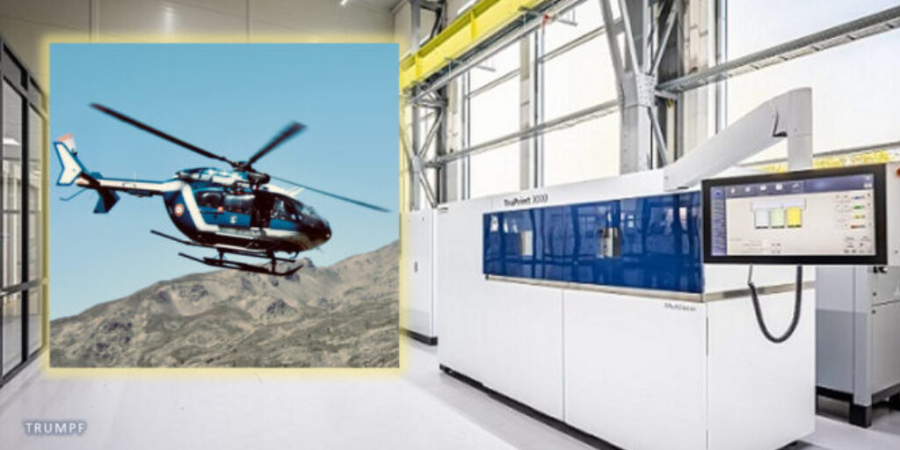
Airbus Helicopters is to use 3D printing technology to produce components for its helicopter vehicles and the aircraft of parent company Airbus.
Airbus Helicopters will use TRUMPF‘s 3D printing technology to produce components for its electric-powered City Airbus experimental high-speed Racer helicopter, as well as the Airbus A350 and A320 passenger aircraft, with structural components made of titanium and high-strength aluminum believed to be the focus. The company is investing heavily in additive manufacturing technology because of its ability to reduce weight and, in turn, bring down fuel consumption and costs. It is said to be exploring the part consolidation of some systems, again to save weight, and values the capacity to reuse powder.
“With innovative manufacturing processes, we are working on the helicopters of the future in Donauwörth,” commented Helmut Fárber, site manager at Airbus Helicopters in Donauwöth. “Among other things, 3D printing helps reduce the weight of components.”
Said Richard Bannmueller, CEO of TRUMPF Laser and System Technology, “Additive manufacturing saves expensive raw material and can lower production costs in the aviation industry. 3D printers only use the material that designers actually need for their components and that ends up taking off in the aircraft.”
Airbus, like many other aerospace manufacturers, has had a keen interest in additive manufacturing technology for several years, with the company recently signing a 3.8 million EUR contract with Oerlikon for the additive manufacture of satellite antenna clusters.
Find heat treating products and services when you search on Heat Treat Buyers Guide.com
Batch or continuous — which equipment is better for your operations? Today’s Heat Treat Radio episode is a lunch & learn to answer your burning question about batch IQ vs. continuous pusher furnace systems. Michael Mouilleseaux of Erie Steel is a boots-on-the-ground expert in North American heat treat, and he’ll share a bit about the history of these systems before getting into the equipment and heat treat processing differences.
Doug Glenn, Heat TreatToday's publisher and the Heat TreatRadio host, Karen Gantzer, associate publisher/editor-in-chief, and Bethany Leone join this Heat TreatToday lunch & learn.
Below, you can watch the video, listen to the podcast by clicking on the audio play button, or read an edited transcript.
The following transcript has been edited for your reading enjoyment.
The History of Batch and Pusher Furnaces (00:52)
Contact us with your Reader Feedback!
DOUG GLENN: Can you talk with us a little bit about the whole history of batch furnace versus pusher furnace?
MICHAEL MOUILLESEAUX: Sure. And thank you for having me!
Interestingly enough, the pusher furnace — which we might say is a more complex piece of equipment than a batch integral quench furnace — preceded the batch furnace. Atmosphere pushers were around prior to World War II. I spoke with a number of folks in the industry and asked, “How could that possibly be, given the level of complexity?” Interestingly, pushers were available because the atmosphere was generated by a charcoal generator.
If you think back to pack carburizing, we used charcoal and some accelerator. You would put it in a closed container, you’d heat it up, and that’s how you carburized things before you had atmosphere furnaces. Utilizing that same concept, they generated an atmosphere, put it in a furnace, and pushers were the first ones to do that.
So, who were the folks who did that? They were AFC-Holcroft, Surface Combustion, and Ipsen, all the usual characters and suspects there.
Pusher furnaces were available in single row and multiple row configurations.
They were heated with gas or electricity. I have to think that the earlier ones were heated by gas. Typically, they employed oil quenching. Although atmosphere cooling could be in the works, to find something of that vintage is very difficult. Maybe someone listening to this will weigh in and say, “Well, let me help you with that.”
The batch integral quench furnace is post World War II. What precipitated the development of the batch integral quench furnace was the development of the atmosphere generator, and that’s thanks to and around 1941 he actually published a book on atmosphere generators. I’m not sure where to find documentation of the patent he was granted for this generator. It might be interesting to discover. But again, Lindberg, Surface, Ipsen, — all these folks had these furnaces in the late 40s/early 50s.
When they started out, these furnaces were relatively small. The furnace might have had a tray that was 12 inches x 12 inches x 8 inches tall. You’d struggle to fit a hundred pounds into something like that.
But the batch furnace is by far the most popular atmosphere furnace that is available. You’ve got a variety of processing capabilities, which makes very flexible. There are a wide variety of sizes, even today; it can be heated with electricity or gas (we’ll talk about that a little bit later). You can have an oil quench furnace, you can use a polymer quench, and you can have a furnace where you atmosphere-cooled the load after it was processed in the primary furnace.
During this discussion, I’m going to use “batch,” “batch IQ,” and “batch integral quench” semi-interchangeably. So, if I say “batch” and I forget the “IQ” or if I say “batch integral quench” — these are all the same pieces of equipment. We have numerous names for the same thing.
DOUG GLENN: Gotcha. You said the continuous furnace came first because the atmosphere was being created by burning charcoal inside the furnace, that created a carbon rich environment?
MICHAEL MOUILLESEAUX: Actually, it was a generator that was pumped into the furnace.
DOUG GLENN: Got it. That was confusing; I was wondering how they were burning charcoal inside a furnace.
MICHAEL MOUILLESEAUX: Actually, it was explained to me that because the pusher furnace was so much larger, when you would open the doors to place or extract a load, the relative pressure drop of opening a door wasn’t that great. So, these primitive charcoal generators could accommodate that.
But in a batch furnace, arguably, the door is one wall of the furnace, and you couldn’t create a sufficient amount of pressure in the furnace. So, it had to wait until we had endothermic generators so that we could establish a furnace pressure higher than atmospheric pressure to make batch furnaces. It’s fascinating.
Basics of the Batch Furnace (05:41)
DOUG GLENN: And as you said, it is probably the most popular furnace used today by many, many heat treaters. Let’s talk about batch furnaces, here we go.
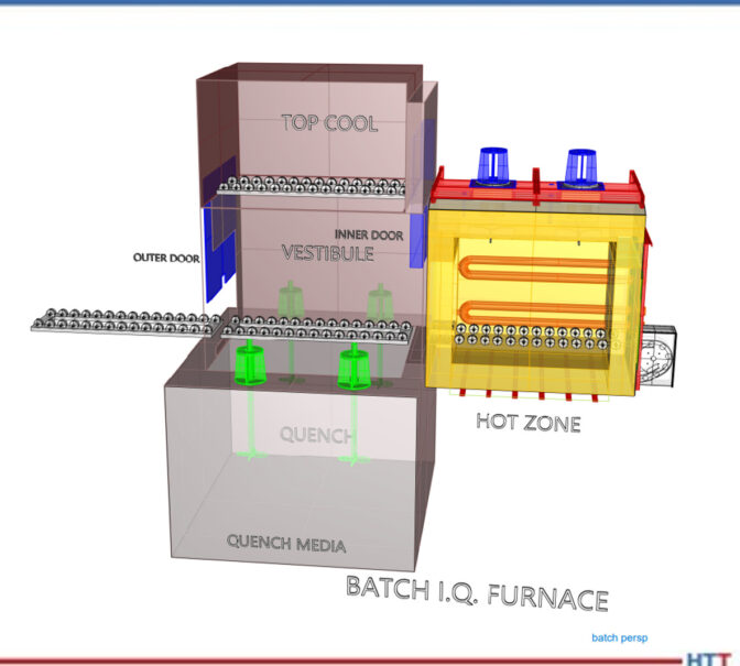
MICHAEL MOUILLESEAUX: Let’s look at the CAD drawing for a batch furnace. The batch furnace is primarily two components. You can see the hot zone — that is the furnace proper. It’s highly insulated, it has radiant tubes in it (so we can put atmosphere in the furnace), and the heating portion does not affect the atmosphere.
It is loaded through a vestibule, and the vestibule is pressurized as well. A load can go into a vestibule, you can close the door, you open the inner door, the load goes into the furnace, you can process it and then, as you can see, you can either quench the load or you can top cool the load.
CAD drawing of a batch furnace.
Common Processes in a Batch Furnace (06:31)
What kind of things can we do in an atmosphere furnace? Answer: operations that do not require quenching. We could stress relieve, we could subcritically anneal, we could supercritically anneal (so, above and below 1350/1400 Fahrenheit), and then we can normalize.
Normalizing is utilized for products like forgings or castings which are made at a very high temperature. You’ve got a number of structures in the component and what you want is a “normal” structure. You want a uniform structure throughout the part so that it can be machined.
Normalizing is typically performed at a high temperature, and it’s put into this top cooled/atmosphere cooled chamber. In the old days, that was termed “air cooling” — it was a rate equivalent if you just set it out in air. These top cooled chambers are somewhat insulated; they have cooling jackets that are in the side, and there is a fan in them so you can circulate the atmosphere through it so that you get uniform cooling throughout the load.
DOUG GLENN: Michael, this isn’t considered high pressure gas quenching though, right?
MICHAEL MOUILLESEAUX: Not even close.
In this animation, we have the load going into the furnace, the vestibule door closes, the furnace door opens, the furnace door closes, we perform whatever process we want, we extract the load out of the furnace, and it goes up into the top cool chamber. It’s then atmosphere cooled. When that is completed, we take the load out.
The time in the furnace could be four hours (plus or minus). The time up in the top cool chamber would probably be an hour or two. Once the load is extracted from the furnace and is put into the top cool chamber, and you reestablish pressure in the vestibule, you actually open the outer door, put another load in and start processing the next load while the initial load is being cooled.
Then, there are processes that require quenching. In degree of simplicity, first there is neutral hardening. Neutral hardening implies that the atmosphere in the furnace is neutral with the carbon content of the steel. So, for a 30-carbon steel, you’d want a 30-carbon atmosphere; for a 40-carbon steel, you’d want a 40-carbon atmosphere. The optimum is to neither enrich nor to deplete the surface carbon; you don’t want to change the chemistry. Typically, neutral-hardened parts are subsequently oil-quenched.
Then, there is carbonitriding. In carbonitriding, you have a high carbon atmosphere. You also introduce ammonia into the furnace. The ammonia dissociates right in the furnace. The carbon and nitrogen diffuse into the surface of the component. is held at a sufficient temperature to attain the case step that is desired, then, again, it is extracted into the vestibule, and it is quenched.
Carburizing would be another process. It’s similar to carbonitriding, except there is no ammonia. It’s only carbon that’s diffused into the surface of the part. Typically, parts that are carburized are oil-quenched.
There are, however, strategies and components where you would carburize, and then you would take the part and you would top cool it. You might take the part out of the furnace, and you may reorient it. So, parts that are distortion-critical may be oriented in one direction for carburizing, and then reoriented for hardening. You may carburize twice as many parts as you harden, so the hardening load would be half the size.
A low temperature process which is more complex is ferritic nitrocarburizing. That, typically, is performed around 1000°F. It is performed in batch furnaces, as well. Typical process cycles for that are going to be, at temperature, an hour and a half/two hours. That process can either be atmosphere cooled or it can be quenched; it depends on whether you’re looking for solid solution hardening or if you’re just looking for the nitrided layer and you’re not trying to do anything to the substrate.
I think that we have an animation for this.
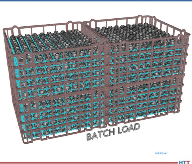
Diagram of a batch system load.
Again, the load is loaded in the vestibule, the vestibule pressure is reestablished, the load is put into the furnace and, at that point, we perform whatever operation it is that we want to do of those previously described operations.
In the animation, you can see that the load is immersed in the quench. Following the quenching operation, it’s withdrawn from the furnace.
The total time for quenching is 10 minutes. When the load is brought up out of the oil, typically you let it sit there and allow it to drip so the precious quench oil you’ve paid your money for can go back into the quench. You’re washing and removing as little quenchant as is possible. In the heat treating operation, quenching is the single most critical portion of the operation.
A Note on Quenching (12:32)
MICHAEL MOUILLESEAUX: When we’re carburizing, we have a portion of an hour where there would be no significant change in the case depth of the part. When we temper the parts, we have hours. You could temper it for three hours, you could temper it for five hours, and you’re not going to have a material change in what’s performed. In the quenching operation, the latitude that you have in quenching is in seconds.
Our typical protocol is that when a load is extracted from the furnace, from the time that the furnace door opens into the vestibule to when the load bottoms out at the bottom of the quench, in a batch furnace, must be 40 seconds maximum.
DOUG GLENN: 40?
MICHAEL MOUILLESEAUX: 40 seconds maximum. Typically, it’s done in 20 or 25 seconds. But it’s 40 seconds maximum. In a pusher, that number is 30 seconds maximum. This is something that you track; it’s data logged. If it exceeds that, at that point, you’re going to have to perform some inspection on that load that is much higher and much more intense had it not taken that much longer.
DOUG GLENN: Can you, very briefly, explain why is it so important? I’m assuming it has something to do with martensite start and martensite finish and all that good stuff, but is there a layman’s way of explaining why the time to quench is so important?
MICHAEL MOUILLESEAUX: Essentially, you want to have the load at a uniform temperature when it goes into the quenchant. If we have a significant variation in the low temperature, from the top to the bottom or the front to the back — even if the quenching operation is completely uniform — we’re going to have a variation in properties, variation in hardness, and certainly the probability of variation in core hardness.
For those things that are distortion-critical, it is absolutely important that the load has a similar temperature, across the load, top to bottom, inside to out, when it’s quenched.
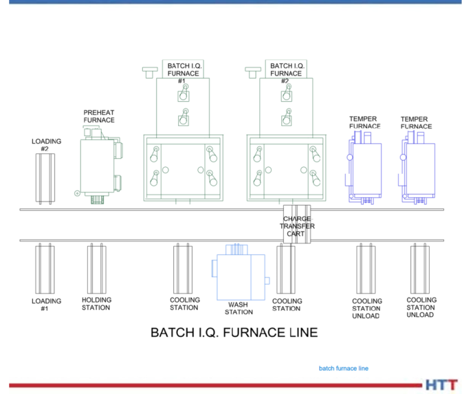
Batch Furnace Systems (15:00)
MICHAEL MOUILLESEAUX: You typically don’t have a singular furnace, you have a system. What’s involved in a system?
What we’re looking at here is a relatively simple system. You have a loading operation. Obviously, the parts need to be loaded in baskets or fixtures. In some way, the load needs to be built. Typically, there is a station for that.
Diagram of a batch system furnace line.
Following loading, it’s put into a preheat furnace. A preheat furnace is identical to what we would call a “temper” or a “draw.” You can thermally clean the parts by heating them up to 800°F. The other thing is that those that you put into that part are 20% the cost of getting those BTUs when you’re putting it in the high heat furnace, so it just makes economic sense. You’re cleaning the parts and you’re preheating the parts.
Then you’re going to put it into the furnace to perform the furnace operation; it’s either going to be top cooled or quenched. If it’s top cooled, you’re going to stop that top cooling operation at 300°F or 400°F. You’re going to put it in a cooling station and allow it to cool to room temperature. If you quench the part, if you’re modified marquenching it, it’s 250°F plus; if it’s quenched in regular oil, it could be 150–180°F.
The next operation is to wash the part. Typically, you don’t want to wash hot parts; you want to allow them to cool to room temperature. Sometimes you do, but more often than not, no.
Then there’s the wash station; you’re washing the parts. Then, you’re taking them out of the washing station and allowing them to drip. Then, you’re going to put them into a temper and you’re going to temper it for three to seven or eight hours, or something of that nature. You extract the load from the tempering furnace, put it in a cooling station, and allow it to cool down to room temperature so you can then unload it.
As you can see, the way that is accomplished is with this transfer cart. The transfer cart extracts the load from the loading table, pushes it into the preheat furnace, pulls it out of the preheat furnace, and pushes it into the batch furnace. Then the batch furnace quenches it, but when the outer vestibule door is opened, the transfer car must go in and get the load and pull it back onto the transfer car. The car pushes it across the aisle into the cooling station, picks it up, puts it in the wash, takes it out of the wash, puts it into the temper, takes it across the aisle when the tempering is finished, extracts it from the temper, and puts in on the cooling station. That transfer cart is an important piece of equipment.
But you can see there are a lot of moving parts to this. And you might ask, “Why would you do this?” Well again, because of the flexibility of the batch furnace. In this example, batch furnace #1 can be performing neutral hardening; batch furnace #2, at the same time, can be carbonitriding; the neutral hardening load finishes and the next load that goes in there could be annealed; after the load is annealed, then you could take a load and it could be normalized; then you could go back and you could neutral harden again.
So, if you don’t have multiple loads of the same thing, this offers a degree of flexibility that almost is not available in any other type of atmosphere processing equipment.
DOUG GLENN: Right. And the fact that you have more than one furnace, more than one high heat furnace, more than one temper furnace, gives you almost (not exactly, but closer to) a continuous process even though each furnace is a “batch,” if you will.
MICHAEL MOUILLESEAUX: Correct.
There are charge cars that are automated, so the charge car knows where the loading station is — it goes to that loading station. You could either have a human unload it or, in the highest degree of automation, it gets there and you have a PLC that is overseeing or supervising this entire operation, and it would know to take that load onto the cart, where to take it next, and what to do. It becomes a semi-automated method of heat treating.
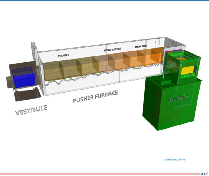
Properties of the Pusher Furnace (19:53)
DOUG GLENN: Let’s move on to the pusher furnace, the continuous system.
MICHAEL MOUILLESEAUX: The pusher furnace, as you can see in this description, contains the vestibule, the furnace, and the quench. We’ve just broken it down into the pusher furnace proper.
Diagram of a pusher furnace.
Loads are put into the vestibule and then, sequentially, they move their way through the furnace. The first zone of the furnace would be what we would call the “preheat” and that’s where we bring the part up to temperature.
In this example, we’re showing boost-diffuse. This is an example where we would be carburizing. The first couple of positions would be a boost. We carburize at a higher carbon content because it diffuses more rapidly at the initial point of carburizing. Then, at the tail end of the carburizing cycle, we reduce the carbon content to what our desired surface carbon content would be.
An example might be: We would start out and we’d boost at 1% or 1, and the diffuse cycle would be .8% carbon. You do that for a couple of reasons: You want to mitigate any retained austenite, so the bar is quenched at a higher carbon. You have opportunity for development of an unacceptable amount of retained austenite. At the extreme, you could start developing carbides and those become very difficult to re-solution. That’s the rationale for having a boost-diffuse. You do that same thing in a batch furnace; I just didn’t describe that as such.
And then the drop zone. We want to reduce the temperature prior to quenching so that we have very uniform quenching properties and if the components that we’re heat treating are distortion-critical, it’s very important as to what the temperature is prior to quenching.
So, we carburize at a high temperature (1700 Fahrenheit/1750 Fahrenheit), because the diffusion rate is much higher at that temperature. But we only want to quench these parts at 1500 or 1550 Fahrenheit because we want to have an absolute minimum amount of distortion.
Every hour, the vestibule door to the quench is going to open and you would cross-push that load into the quench vestibule, you would close the door, and just as the animation described in the batch furnace, that load would drop on an elevator into the quench.
Now that we’ve done that, we have an opening. That last position is open. So, we go to the vestibule on the front end of the furnace, we open that door, we put a load in there, we close the door, and we’ll close it long enough for us to reestablish the furnace pressure (no more than 3–5 minutes). Once we’ve established furnace pressure, we can open the door between the vestibule and the first preheat zone, and then to the left of the vestibule is going to be a mechanism for pushing these loads, hence the term “pusher”? Could it be hydraulic? It could. Could be mechanical? Both are employed.
What you’re doing is pushing it further by one position. Because the last position is open, the second to the last load progresses into the last position, the load that you put in the vestibule goes into the first position.
DOUG GLENN: A couple quick questions: Really, the sequence starts with the load being pushed out of the furnace into the quench vestibule and then dropped in. That leaves that last spot open in the furnace. Then everything else starts and we push it all down, correct?
MICHAEL MOUILLESEAUX: You are correct.
DOUG GLENN: In this illustration, it looks like there are divisions between each of these different locations. In the preheat, it looks like there are three or four; in the boost-diffuse, it looks like you’ve got two or three. Those aren’t actually physical barriers; You’re just showing where the load would progress to, correct?
MICHAEL MOUILLESEAUX: You are correct.
DOUG GLENN: Are there any chamber divisions in a pusher furnace?
MICHAEL MOUILLESEAUX: In a pusher furnace, you have arches above the load and that helps to compartmentalize. The key word there is “helps.” You don’t have an actual compartmentalization.
Let’s say that we want to perform a carburize at 1700°F in this furnace. If you had three preheats, you may want to perform these somewhere below the 1700°F with the last position being at 1700°F so that the load that goes into the carburizing zone is at temperature and it’s ready to accept carbon.
The carburizing zone would all be at the same temperature, but you have to understand these parts are all at 1700°F and we want to quench it at 1550°F, let’s say. We have two positions that we are going to allow the load to cool down to 1550°F.
So, would you want a zone arch there? I think that you would, yes. Would you want a fan in those zones? If you had a fan in those zones, and you are circulating the atmosphere through those loads, you have a better opportunity to attain a uniform temperature from the top to the bottom of the load than if you did not.
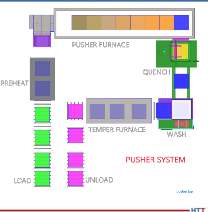
Diagram of a pusher furnace system.
MICHAEL MOUILLESEAUX: Here’s a pusher furnace system. Typically, but not always, pushers are put into a system because you have multiple operations that you must perform. This example is in a U-shape. The loading and unloading are next to each other. This could be a linear layout.
In another life, I worked for a company in Syracuse, New York that had 14 furnaces that were all linearly oriented. So, the person on the front of the furnace did one thing, the person on the back of the furnace did another thing, and they really didn’t communicate.
I, personally, am not a fan of that. I like this operation because you can have one or two people performing the loading and unloading operation, and you could have a furnace operator who would be responsible for the overall control of this piece of equipment.
You can see that we have four loads here that are in whatever way we chose to fixture them — baskets, fixtures, or whatever it might be. We’ve put a couple of parts in a preheat so we could perform that same cleaning that we talked about in preheating the load with low-cost BTUs. The preheat then goes into the vestibule, the loads progress down through the furnace as we described, you get to the end and that load is quenched. When the load comes out of the quench, just as in the batch furnace, it’s going to be 150–200°F plus. We want that to cool down to room temperature because the next operation is going to be washing.
After the load to cools down to room temperature, we then put it in the wash. Following the wash operation, you might have a drip station. So, whatever it was that you have washed off in the water, you don’t want that to go into the temper. Following the drip station, then you would go into the tempering furnace. Here we’re showing three positions; it could be three, it could be six, it could be nine. This is just an example.
Following the tempering operation, we would go out and in that first position, you might have a blower underneath and you would be circulating, room temperature air through it up into a duct work ahead and that’s how you would cool the room down to low temperature. Those loads would progress down that unload station so, at the very end, you are unloading the parts, perhaps for a subsequent shop blast cleaning operation or development of rust preventative or maybe they’re just put back into the customer’s container.
In a captive operation, they might go into a container where the parts would go on to a subsequent grinding or hard-turning operation.
This can be automated. Here you can see that the loads progress into the preheat, they progress through the furnace, they go into the quench, and they’re put into the wash. It’s quick.
Diagram of a pusher furnace load.
DOUG GLENN: Yes. It doesn’t happen this fast in real life, everyone!
MICHAEL MOUILLESEAUX: In the temper, the load exits the temper and goes into the unloading station. The point of this is to show that it progresses through the furnace.
The advantage is that you have relatively small loads that you’re processing, there is a very consistent process in the pusher furnace, and what you’re on for is that however you’ve designed this system, every load goes through every station. You don’t have an opportunity to easily extract a load as quenched and not wash it. It can be done. You could have a furnace designed to do that, but it’s not easy. After it’s washed, as you can see in this animation, typically it’s going to progress into the temper. Could you design a station that would allow you to offload it? You could, but normally that’s not how that’s done.
So, the load progresses through the temper and then you go in to where it is then subsequently unloaded.
If the batch furnace’s strong suit is the fact that it is extremely flexible — particularly in a “systemic” way — the pusher furnace’s strength is its productivity. °
DOUG GLENN: Yes, higher levels of productivity. But you’ve got to have, if not the same product, at least the same process on whatever it is you’re putting in there.
MICHAEL MOUILLESEAUX: Bingo. That’s exactly what you must have there, yes.
About the expert: Michael Mouilleseaux is general manager at Erie Steel LTD. Mike has been at Erie Steel in Toledo, OH since 2006 with previous metallurgical experience at New Process Gear in Syracuse, NY and as the Director of Technology in Marketing at FPM Heat Treating LLC in Elk Grove, IL. Having graduated from the University of Michigan with a degree in Metallurgical Engineering, Mike has proved his expertise in the field of heat treat, co-presenting at the 2019 Heat Treat show and currently serving on the Board of Trustees at the Metal Treating Institute.
How can increased cybersecurity measures benefit today’s heat treaters and their clients? Find out more with an exploration of the coming changes in CUI and the way these changes could affect heat treating companies.
Today’s read is a feature written by Joe Coleman, cybersecurity officer at Bluestreak Consulting™. This column was first released in Heat Treat Today’sSeptember 2023 People of Heat Treat print edition.
Introduction
Joe Coleman Cybersecurity Officer Bluestreak Consulting™ Source: Bluestreak Consulting™
This 10th article in the series from Heat Treat Today’sCybersecurity Desk will explain some of the changes that are being proposed in the IPD (Initial Public Draft) of NIST SP 800-171 Revision 3. On May 10, 2023, the National Institute of Standards and Technology (NIST) released a draft version of Rev. 3 for Special Publication (SP) 800-171, the foundational framework of requirements for protecting controlled unclassified information (CUI). The final version of NIST SP 800-171 Rev. 3 is expected to be released in early 2024.
Don’t panic about these proposed changes in Rev. 3. If you handle CUI and you are working towards your compliance, continue to implement Rev. 2. Don’t wait until Rev. 3 is fully released to start. Remember, DFARS mandates that if you are a DoD prime contractor or subcontractor with CUI, you need to be compliant with NIST 800-171 Rev. 2 as well as CMMC Level 2 or 3 certified. CMMC certification deadline is in 2025 and it’s fast approaching.
Modifications & Additions to Rev. 3
The changes in Rev. 3 should have a positive impact on your ongoing compliance management program. They simultaneously made the requirements easier to understand and implement while also preserving and even adding flexibility that allows companies to make risk-based decisions about their environments and the data managed in those environments. These include the merging, addition, removal,
and clarification of several different requirements. The most obvious difference is that the requirements went from 110 controls down to 109. This was because they had withdrawn 27 of the original controls (most are migrated into another existing control) and added 26 new requirements.
Categories of Changes
• 18 Controls with “No Significant Change”: Editorial changes to requirement; no change in outcome.
• 49 Controls with “Significant Change”: Additional detail in the requirement, including more comprehensive detail on foundational tasks for archiving the outcome of the requirement.
• 18 Controls with “Minor Changes”: Editorial changes. Limited changes in the level of detail and outcome of requirements.
• 26 Controls with “New Requirements”: Newly added requirement in IPD SP 800-171 Rev. 3.
• 27 Controls with “Withdrawn Requirements”: Requirement withdrawn.
• 53 Controls with “New Organization-Defined Parameter (ODP)”: New ODPs can apply to all change types with the exception of withdrawn requirements. Each requirement includes one or more new ODPs.
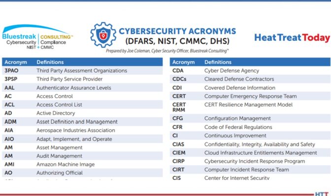
Click on the Image for a full list of Cybersecurity Acronyms
Implications for Heat Treaters
What has not changed is that companies that handle CUI must comply with the NIST 800-171 cybersecurity standards. Failure to comply can result in significant consequences, including loss of contracts and damage to the company’s reputation. With the release of Rev. 3, heat treaters must ensure they are up to date with the latest security requirements. One of the most significant changes in Rev. 3 is the addition of new security requirements. Heat treating companies must review these new requirements and ensure they have implemented the necessary controls to meet them. Also, organizations must review the updated requirements to ensure they meet the latest best practices. The reorganization of the security requirements may also impact heat treaters. The alignment with the NIST Cybersecurity Framework provides a more comprehensive approach to security. However, some companies may need to adjust their current security programs to align with the new structure. By staying informed and implementing the necessary controls, heat treat organizations can ensure they are adequately protecting CUI and meeting their compliance obligations to their clients.
About the Author:
Joe Coleman is the cybersecurity officer at Bluestreak Consulting™, which is a division of Bluestreak | Bright AM™. Joe has over 35 years of diverse manufacturing and engineering experience. His background includes extensive training in cybersecurity, a career as a machinist, machining manager, and an early additive manufacturing (AM) pioneer. Contact Joe at joe.coleman@go-throughput.com.
Find heat treating products and services when you search on Heat Treat Buyers Guide.com
This presentation was featured in a Heat Treat Radio episode with Justin Dzik, manager of business development, and Ben Witoff, manager of data engineering, at Fives North American Combustion, Inc. In the episode, Heat Treat Radio #77: Algorithmic Combustion Tuning With Justin Dzik and Ben Witoff at Fives, Heat Treat Today publisher Doug Glenn learns about a never-before-seen combustion system tuning technology from Justin and Ben. Hear from the experts themselves how this system will save time, money, and personnel and can be adapted to virtually any furnace system.
An excerpt from the episode: "Where we’ve focused on is direct-fired heat treat furnaces and torch furnaces, and we’re looking to branch out into other things. We’ve even had discussions internally of using this on resistive heaters for electric heaters because we know 'the green wave' is coming. The product itself has been stated pretty well. The algorithm has no idea that it’s even a furnace. It could be applied to pretty much everything."
Heat Treat Todayoffers News Chatter, a feature highlighting representative moves, transactions, and kudos from around the industry. Enjoy these 21 news bites that will help you stay up to date on all things heat treat.
Company Chatter
HarbisonWalkerInternational (HWI), a North American supplier of refractory products and services, announced that its new Alabama One (AL1) manufacturing facility for steel customers in the southern United States is on track to open before the end of 2022.
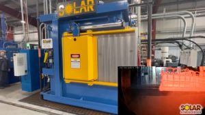
Solar Atmospheres of Western PA announced their newly designed vacuum oil quench furnace (VOQ) has passed startup protocol
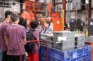
On July 6, Solar Atmospheres hosted over 40 high school students enrolled in the Summer Engineering Institute (SEI) at Lehigh University. The SEI program is a two-week residential program. Students are nominated by faculty of local high schools, and the program specifically targets students who might have limited opportunities to study in the fields of science, technology, engineering, and math (STEM). They received a tour of the campus that emphasized cutting-edge technologies in heat treating and manufacturing.
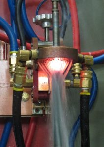
Advanced Heat Treat Corp. (AHT) announced the addition of UltraGlow® Induction Hardening at its location in Cullman, Alabama.
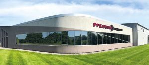
Pfeiffer Vacuum opened up a new 40,000 square foot facility May 13, 2022. This facility is located at 4037 Guion Lane, Indianapolis, IN.
New Solar Atmospheres of Western PA VOQ furnace
SEI students at Solar Atmospheres
Induction equipment now at AHT’s Alabama location
New Pfeiffer Vacuum system in Indianapolis
Personnel Chatter
Advanced Heat Treat Corp. (AHT) announced that Chris Williams has joined as the new regional sales manager for its location in Cullman, AL.
Industrial Heating Equipment Association (IHEA) recently announced its 2022–2023 Board of Directors and Executive Officers. Serving as President is Jeff Valuck of Surface Combustion, Inc.; Vice-President is Brian Kelly of Honeywell Thermal Solutions; and Treasurer is Jeff Rafter of Selas Heat Technology Co. LLC. Scott Bishop of Alabama Power – a Southern Company assumes the Past President position.
IHEA welcomed to the Board of Directors Ben Gasbarre, the of Sales & Marketing for Gasbarre Thermal Processing Systems, to the Board of Directors.
The Supervisory Board of Advanced Graphene Products has been formed, appointed by the Ordinary General Meeting on June 24, 2022. Peter Zawistowski, a graduate of the Częstochowa University of Technology, Kozminski University (MBA) and the Massachusetts Institute of Technology (Executive Program in General Management), became the new chairman of the Supervisory Board. Peter has been the managing director of SECO/VACUUM operating in the American market since 2017.
The Plibrico Company, a supplier of monolithic refractories and installation services, is excited to announce and welcome Shawn Story as its new engineering manager.
Chris Williams, Regional Sales Manager, AHT
The 2022–2023 IHEA Board of Directors
n Gasbarre, Executive Vice President, Gasbarre Thermal Processing Systems
Shawn Story, Engineering Manager, Plibrico Company
Kudos Chatter
Space-Lok, Inc. met the requirements of Nadcap accreditation and achieved approval for heat treating.
ALD Thermal Treatment, Inc.'s Port Huron facility received the General Motors Supplier Quality Excellence Award for outstanding quality performance for the 8th year in a row. Criteria for this award include zero official customer complaints for 12 months and quality performance of less than one defective part per million.
Advanced Heat Treat Corp. (AHT), a provider of heat treat services and metallurgical solutions, announced that it has renewed its Nadcap accreditation in heat treating (ion and gas nitriding) and passed its Aerospace Quality System (AC7004) audit. The company has also added additional AMS specifications to its scope: AMS2759/6 and AMS2759/12.
Braddock Metallurgical announced the renewal of a Nadcap accreditation at their Tampa, FL location. The administrator, , has also determined that the heat treater has gone beyond industry requirements and so earned Merit recognition.
SECO/WARWICK in India celebrated its fifth anniversary of its establishment in May, although they have been operating in that market since.
Metalex Thermal Specialties, a heat treat service provider, announced that it has achieved AS9100:2016 and ISO 9001:2015 certification for the quality management system implemented by its heat treating facility in Berthoud, CO.
Paulo’s Cleveland plant in Ohio has earned Honeywell approval for all HIP processing with no restrictions.
The MTI Educational Foundation announced that it awarded Eric Roth of Tucson, Arizona (University of Arizona) the $15,000 Founders Scholarship.
ITP Aero UK Limited was awarded their latest Nadcap certification for Heat Treating with full 24-month merit and accreditation length.
Maryam Razavipour, a senior engineer at Lumentum, was selected by the Heat Treating Society Board of ASM International for the 2022 HTS/Bodycote Best Paper Award for her paper, “Data-Driven Design Framework for Laser Heat Treatment Process of Cold Spray Coating.”
Nadcap accreditation for Space-Lok, Inc.
Supplier Quality Excellence Award for ALD Thermal Treatment, Inc.
Nadcap Merit recognition for Braddock Metallurgical Tampa, FL facility
Eric Roth, recipient of Founders Scholarship from MTI Educational Foundation
Maryam Razavipour, Sr. Engineer of Manufacturing Process Development, Lumentum
Heat Treat Today is pleased to join in the announcements of growth and achievement throughout the industry by highlighting them here on our News Chatter page. Please send any information you feel may be of interest to manufacturers with in-house heat treat departments especially in the aerospace, automotive, medical, and energy sectors to bethany@heattreattoday.com.
Find heat treating products and services when you search on Heat Treat Buyers Guide.com
The monthly Industrial Heating Equipment Association (IHEA) Executive Economic Summary released in December gives forecasts for Q4 results and takes a look into the start of 2023. The 3.9% growth from Q3 is not expected to be matched in Q4, but the spending power of the consumer holds out hope for battling recession.
The 3.9% growth from Q3 is not expected to be matched in Q4 and beyond, but the spending power of the consumer holds out hope for battling recession. The thought is that inflation highs have peaked, and interest rates could lower about halfway into 2023. Heat treaters should note that applicable indices are remaining steady while still dealing with supply chain problems and work force shortages. Of the 10 economic indices in this report, 6 sectors are steady or seeing growth; while 4 are on a downturn.
Holding steady with biggest strength found in automotive. Source: IHEA
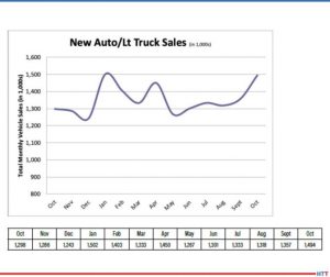
The categories included in seeing maintenance and growth are: New Auto & Light Truck Sales, Steel Consumption, Industrial Capacity Utilization, Metal Pricing, Durable Goods, and Factory Orders. Automotive sales are strong; people are wanting and needing to replace vehicles they've maintained for a long time. "People want new and they are confident enough in their job security to buy a new vehicle."
Automobiles are still in heavy demand due to supply chain issues and need to replace older vehicles. Source: IHEA
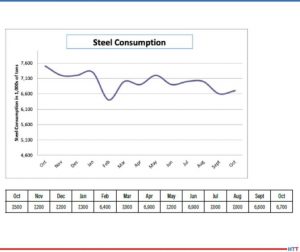
There are no surprises from the Steel Consumption reports, as the "big three sectors are all performing about as expected – vehicle manufacturing, construction and the oil and gas arena." Metal Pricing is seeing a A Tale of Two Cities because copper is affected by political tensions around the world, but aluminum is seeing strong demand, particularly for the aerospace industry.
Interest rates are prohibitive for single-family home purchases. Source: IHEA
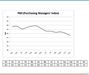
Those indices that are in decline or experiencing drops are: New Home Starts, Purchasing Managers Index (PMI), Capital Expenditures, and Transportation Activity. New home purchases are difficult for those buyers because the interest rates are high. There is a bit of a bright spot for heat treaters since multi-family home sales are still strong; this means metal products are needed - appliances, window frames, and construction components.
Manufacturers are showing caution in purchases. Source: IHEA
The PMI "is always a good indicator of overall industrial activity as the purchasing manager will be doing what they do at the start of any industrial process." In the report it's down to 47.7; not an emergency, but very uncomfortable level.
Anne Goyer, Executive Director of IHEA
The report on these indices takes a middle-of-the-road approach. There are no alarmingly sharp drop-offs in the reports, neither is there any drastic growth into the positive numbers; it all comes down to inflation. Economic markers are such that the interest rates are as high as they will get indicate a drop about halfway through the new year. The report looks for some lowering of the numbers to"between4.25% and 4.50%" while the Fed members think the rate "may top out at 5.1%."
Check out the full report to see specific index growth and analysis which is available to IHEA member companies. For membership information, and a full copy of the 11-page report, contact Anne Goyer, executive director of the Industrial Heating Equipment Association (IHEA). Email Anne by clicking here.
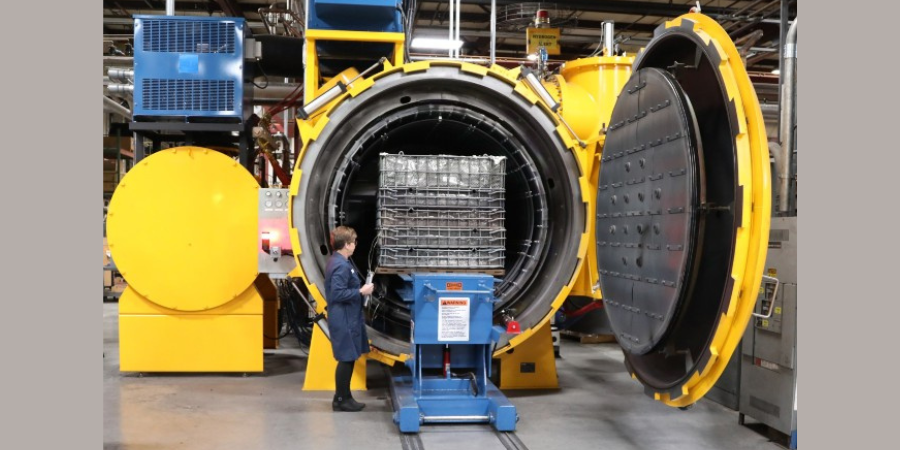
Solar Atmospheres Souderton, PA incorporated a high-production vacuum furnace with a work zone of 48"x48"x72" and a weight capacity of up to 7,500 lbs/batch. The furnace doubles the facility's hydriding and de-hydriding capacity in the reclamation of titanium and tantalum materials.
Maciej Korecki Vice President of Business of the Vacuum Furnace Segment SECO/WARWICK
A manufacturer has chosen a heat treat vertical vacuum furnace designed to perform low-pressure carburizing for the large structural elements (gearboxes) used in wind power plants.
SECO/WARWICK Group, a manufacturer with North American locations, provided the furnace that combines two technologies: atmospheric and vacuum processing. This system provides: process purity, heating uniformity, and elimination of the oxidation effect at the grain boundary. The product solves the problem of high energy and process gas consumption by the partner’s old furnaces, and shortens the carburizing process.
"The Pit-LPC technology . . . increases the safety for users, because it does not involve explosive and flammable gases. LPC eliminates direct CO₂ emissions from the carburizing atmosphere,'" commented Maciej Korecki, vice president of the Vacuum Products Segment at SECO/WARWICK Group.
Find heat treating products and services when you search on Heat Treat Buyers Guide.com
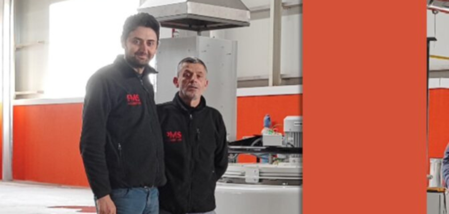
PMS Alüminyum, an aluminum extrusion company, has added a nitriding system from a North American based company that also has international locations to enhance its production capabilities and meet the increasing demand for high-quality, metal profiles across industries including automotive, construction, solar energy, defense, aerospace, and rail.
Previously outsourcing this process, PMS Alüminyum made the decision to bring nitriding operations in-house for streamlined logistics coordination, long-term cost savings, improved availability of ready-to-use dies, and faster turnaround times. Moreover, the growing number of dies to be treated made in-house processing a more viable and cost-effective solution.
The Nitrex pit-type furnace, model NX-1020, with Nitreg® controlled nitriding and Nitreg®-C controlled nitrocarburizing technologies, provides capabilities for processing H11 and H13 dies.
The system was installed in the extrusion company's new facility in November 2022 that also houses an extrusion press and powder coating lines.
Find heat treating products and services when you search on Heat Treat Buyers Guide.com
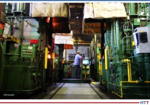
In 1947, amidst a global war that touched every corner of the world, a small heat treat company emerged to serve the thriving and diverse manufacturing market of northeast Ohio. That company, Ohio Metallurgical (Ohiomet), was started by William Latiano and Frank Monaco with only a few salt pots in Lorain, but grew into a larger plant in Elyria, adding vacuum, shaker, and integral quench furnaces. Years later in 1977, Don Gaydosh, who was the general manager at the time, purchased 70% of the company, along with fellow employee Jerry Pragg. In 1990, John Gaydosh followed in his father’s footsteps and is the current president and owner.
Contact us with your Reader Feedback!
The company has now grown to include 78 employees who are trained in four core values: Be client focused, be dependable, do business with integrity, and always be improving.
One way they accomplish their first value is by scheduling production based on the client’s need. In order to be dependable and operate safely, efficiently, and with high quality, the company invests in new equipment and controls. Since 1990, almost all equipment has been replaced completely, though a few older furnaces are still in use but with upgraded, modern controls.
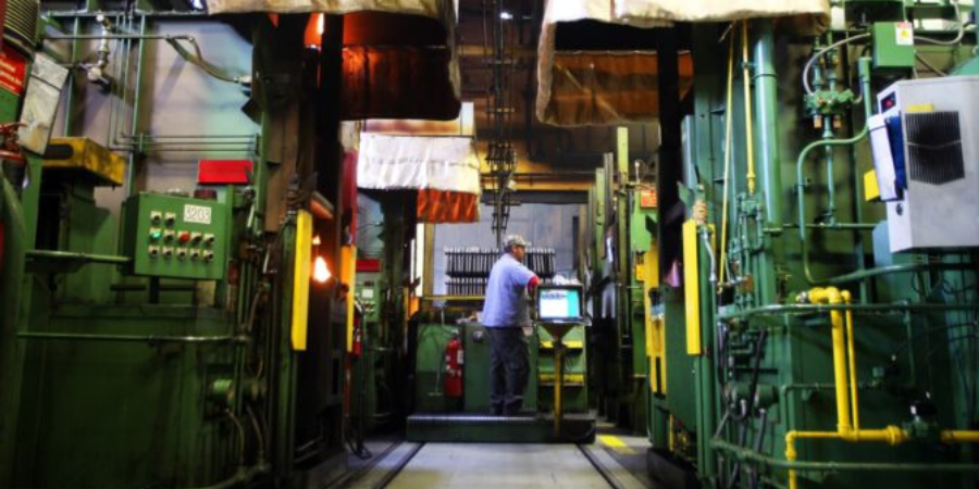
Heat treat operations at Ohiomet Source: Ohiomet
To implement their fourth value of always improving, Ohiomet regularly updates its control systems to reduce operator errors and increase accuracy. Using an in-house customized SCADA software package, they monitor furnaces in real-time, so the operators and supervisors can be notified if process parameters are outside of preset parameters.
With their updated equipment and software, the company serves the automotive, aerospace, military, and mining industries, and more. While the integral quench lines containing 12 IQ furnaces make up the largest part of their business, they also offer multiple types of processes and services from one location. In addition to their IQ lines, they have vacuum furnaces capable of 2-bar nitrogen gas quench, bright age hardening, tempering, and annealing, all of which are qualified to meet AMS2759 specifications and are Nadcap accredited.
In addition to these processes, Ohiomet has both automatic and manual straightening equipment, induction equipment with various frequencies for use on vertical and horizontal scanners, and bell furnaces performing atmosphere annealing and stress relieving. A Nadcap accredited, modern quality control laboratory contains multiple automated microhardness testers along with a metallograph with digital imaging capabilities.
Ohiomet heat treats ribs used in crash test dummies Source: Ohiomet
Among the unique items they have been heat treating are the ribs used in crash test dummies. They harden and temper the steel crash test dummy ribs and the ribs are fitted with sensors to detect how extensive the damage would be in a real car wreck.
While remembering their humble beginnings, Ohiomet looks to the next five to ten years anticipating an increase in automation, not only in material handling, but also for machine control, allowing them to continue fulfilling their founding principle of serving the manufacturing market of northeast Ohio.
Find heat treating products and services when you search on Heat Treat Buyers Guide.com


 Heat Treat