“It is the time to dare and endure.” Winston Churchill made that statement in 1940, and it is apropos today, as hopefully, many of us are coming to the end of the “stay at home” quarantine and will soon be free to roam again. It has also been said that it is during particularly difficult times where possibilities are mined and take flight. We will need those encouraging words in the days, months, and perhaps years ahead as evidenced in the latest Industrial Heating Equipment Association’s (IHEA) Executive Economic Summary. The report states, “This may well be the most distressing assessment of the U.S. (and global economy) since the recession of 2008. None of the bad news that follows will come as any surprise to anyone as we are all quite aware of the damage that has been caused by the reaction to the COVID 19 pandemic.”
The report explains the difference between the 2008-09 recession and that of 2020 – the current recession is an artificial one created by the forced shutdown of the economy. The U.S. enjoyed a robust economy and healthy job numbers at the beginning of the year. “The potential silver lining to all of this is that government … can reverse the process. The day that lockdowns are declared at an end, there will be recovery. Consumers will consume again, employers will hire again, producers will produce again. How much and how fast will be the prime questions.”
In the meantime, however, “Of the twelve indicators followed in this index, there are only four that are still trending in a positive direction and they will not be holding that distinction for long.” The durable goods numbers and factory orders numbers rose a little, but this only indicates there has been a delay in terms of industry response. The activity in the durable goods category is a lagging indicator. There has not yet been enough time for the reduction in activity to manifest in the numbers, i.e., airlines, heavy construction equipment, oil field machinery, farm equipment which have all taken major hits in decline.
Durable goods tracked a bit higher this month, however, be aware that its activity is a lagging indicator.
The summary continues, “The improvement in the transportation numbers may be a bit more realistic. There has been high demand in the parcel sector as everybody has been ordering things delivered.” The other sectors in transportation have not fared as well like ocean cargo, air freight, and the rail sector.
The transportation sector is showing some positive development.
The only other area that experienced a gain was in capacity utilization, “but that will shift as there is now considerably more slack in the system than was the case earlier.” Normally these numbers would reflect the pushes and pulls of supply and demand, but that process has been interrupted … and now almost every business has an overcapacity concern.
We are all living in a “waiting” mode anticipating the “all clear” proclamation. Then, as the summary report concludes, “Once some measure of control is achieved, the economy will be restarted, and then the focus will be on the speed of recovery.”
The report is available to IHEA member companies. For membership information and a full copy of the 12-page report, contact Anne Goyer, Executive Director of the Industrial Heating Equipment Association (IHEA). Email Anne by clicking here.
Steeltech LLC is one of the nation’s leading manufacturers of heat and corrosion resistant materials. We are seeking highly motivated and qualified candidates to join our outside sales team.
The ideal candidate will have sales experience specific to the industries we supply. Industries include: heat treat, steel mill, lime & cement processing to name a few. 3-5 years of sales experience in these industries is preferred. The position requires extensive travel within a designated region of the US. Potential territory will be discussed during the hiring process.
Steeltech offers a competitive compensation and benefits package.
Interested applicants should send their resume to:
Climate change and fossil fuels are topics that can spur many lively conversations. In today’s Heat Treat TodayTechnical Tuesday feature, explore their connection as it relates to heating industrial furnaces in the future with Dr. Joachim G. Wüenning, president, WS Inc. and an expert in clean efficient combustion.
Many people view climate change as the biggest threat to mankind. Technical and social efforts will be required to meet the goals, formulated in the “Paris Climate Agreement,” to limit global warming to less than 35.6° F (2° C).
Combustion of fossil fuels is by far the largest human contribution to global warming. Fossil fuel-fired power plants and internal combustion engines are already in the public focus. The transformation to alternative drives for vehicles has just started, and the days of coal-fired power plants are numbered.
Combustion of fossil fuels for industrial furnaces is also a large contributor to greenhouse gases and air pollution. The industrial heating sector is not in the public focus yet, but that will change soon; therefore the topic should be addressed proactively.
For mid- to long-term future industrial process heating, there are three main scenarios:
heating with renewable electricity, or
heating with non-fossil fuels, or
a combination of both.
Humans used non-fossil fuels for hundreds of thousands of years and are returning to that habit after a short period of about 250 years where fossil fuels were primarily used.
Reducing CO2 Now and In the Future
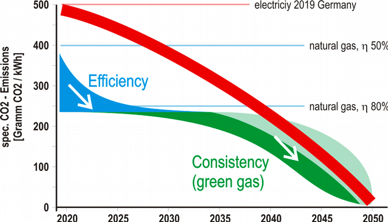
Heating a furnace using electricity is locally CO2 free, but an even greater amount of CO2 is emitted at power plants since the majority of electricity is generated by burning fossil fuels. For every kilowatt hour (kWh) produced, roughly one pound (~0.45kg) of CO2 is emitted into the atmosphere [1]. This is true for Germany, and the figures for the United States are in the same range.
Heating an industrial furnace with a typical temperature of around 1832°F (1000°C) with natural gas produces about 0.4kg CO2 for every kWh of available heat for a cold air burner, and less than 0.25kg/kWh CO2 when using a recuperative or regenerative burner where waste heat is recovered using a heat exchanger.
So, the short-term measure to reduce CO2 emissions is to use an efficient burner with heat recovery or to switch from electric to natural gas heating, which can cut CO2 emissions by 50% or more.
For a further reduction, we have to wait until electricity generation becomes predominantly regenerative, or we have to use green, non-fossil fuels. The possible paths to non-fossil heating of industrial furnaces are drafted in Figure 1. It shows that the short-term action should be improving the efficiency of burner systems or a switch from electric to gas heating. In the mid- to long-term future, there should be a healthy competition between non-fossil fuel gas and electricity, driving the prices for non-fossil energy down.
Figure 1
Changing Fuel Compositions
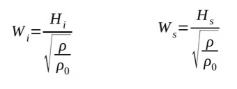
The most relevant characteristic for the interchangeability of fuel gases is the Wobbe Index (Figure 2), with the lower or upper heating value (Hi, Hs), the density of the fuel gas (r) and the density of dry air (r0). Fuel gases with the same temperature, pressure, and the same Wobbe Index will provide the same energy output from a burner. If the Wobbe Index is changing, the flow must be corrected by changing the fuel gas pressure or a flow throttle device to keep the burner power constant.
Figure 2
In most cases, the air does not need to be corrected since the ratio between stoichiometric air ratio and lower heating value is about 0.95 m3/kWh for common hydrocarbons. That means that a burner with a given heating power needs the same amount of air even when different fuel gases are used. A good rule of thumb is that one cubic meter per hour of air is required for every kilowatt of heating power.
If hydrogen is used as a fuel, about 15% less air is required. So, when hydrogen is added to natural gas and the fuel gas flow is corrected but the air flow is left unchanged, the system would be operated with somewhat more excess air, slightly less efficient but safe.
If gas fluctuations will occur in the future, adjusting the burners with more excess air would be an easy measure to ensure safe operation. With an effective heat recovery system and low exhaust gas temperatures, efficiency losses would be minimal.
Fuel Gases With High Hydrogen Content or Pure Hydrogen
The flame speed of hydrogen is much faster compared to hydrocarbons. That can cause some problems, especially in premixed burners where a flashback can occur. Another challenge resulting from faster combustion could be higher flame peak temperature leading to higher thermal NOx emissions. Modern low NOx methods are available to address this problem.
A positive effect of hydrogen can be a more reliable and easier ignition of burner systems. Many industrial burner systems can be operated with high percentages of hydrogen or with pure hydrogen with little or reasonable modifications.
Fuel Gases Containing Fuel Bound Nitrogen
Using ammonia or bio-gases with fuel bound nitrogen will produce excessive amounts of NOx-emissions when burned in most burner systems. There are a number of options to achieve low NOx-combustion with fuel bound nitrogen.
One method is fuel conditioning where fuel bound nitrogen is broken up into molecular nitrogen. This was successfully demonstrated using a stainless steel reactor in combination with a flameless oxidation burner system.[2] Another method would be exhaust gas cleaning by selective (SCR) or non-selective (SNCR) catalytic exhaust gas cleaning. Both processes require large investments and operating costs and should only be used if other options are not available.
The development of combustion systems with integrated treatment of fuel bound nitrogen would be the preferred method and will be an important topic for combustion research in the coming years. One approach is multi-stage flameless oxidation [3].
Fuel Conditioning
Fuel conditioning might be required to keep fuel gas properties within regulated limits inside the gas transport and distribution grid or for certain customers with special requirements. Fuel conditioning can be performed by blending different gases or by changing their compositions by using reformers or gas separation units like pressure swing adsorption (PSA) or membrane technology.
If future regulations propose a certain hydrogen content in the fuel gas grid, strategically placed steam reformers could keep the hydrogen content within certain ranges, even if there is no regenerative electricity available to operate electrolysers.
Reformers could also crack ammonia, ethanol, or methanol before being used as fuel gas to heat processes.
Outlook
There are several options towards non-electric, fossil-free industrial process heating. All these options have to be thoroughly investigated to keep a number of options open for future energy systems. The energy system of the future will be based on regenerative power generation but it will involve additional energy carriers to store and transport the energy. There are some challenges for combustion but there is no doubt that these can be overcome.
A fair and open competition between the different energy options will create the best solutions for society and the planet. A planned economy will not provide the fertile soil for innovations and entrepreneurship necessary to meet the challenges.
References
[1] German Environment Agency, CO2 Grid Emission Factors from 1990 – 2018 for the German Energy Mix, March 2019
[2] Domschke T., Becker C., Wüenning J.G., Thermal Use of Off‐Gases with High Ammonia Content – a Combination of Catalytic Cracking and Combustion, Chem. Eng. Technol., 21: 726-730
About the Author: Joachim G. Wüenning is president of WS Wärmeprozesstechnik GmbH and his area of expertise is in clean efficient combustion, FLOX—flameless oxidation, heat recovery, radiant tubes, and recuperative, regenerative burners. This article originally appeared in Heat Treat Today’sMarch 2020 Aerospace print edition.
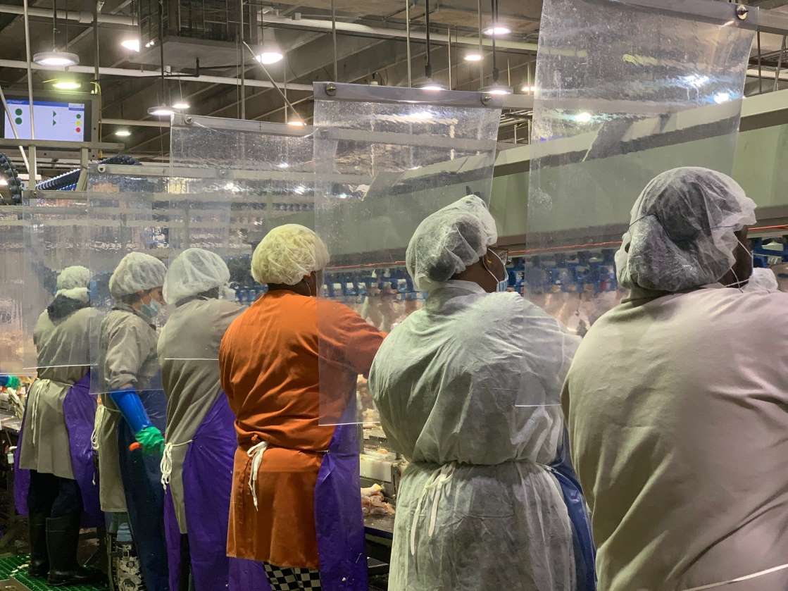
Businesses have been taking extra precautions lately for the well-being of their employees and customers. The Centers for Disease Control (CDC) recommends that employers should have a COVID-19 health and safety plan to protect employees that includes placing barriers (e.g., sneeze guard) between employees and customers and employees working in close proximity.
GermBlock™ cough and sneeze shields (source: Rockford Systems, LLC)
Rockford Systems, a specialist in industrial combustion safety solutions for companies that use thermal processes in their industrial operations, is helping organizations protect employee health and safety by launching its new GermBlock™ line of cough and sneeze shields.
GermBlock™ shields, designed for industrial, commercial, clean room, and retail settings, limit the spread of airborne droplets resulting from coughing, sneezing or speaking from reaching a nearby person, therefore helping to mitigate COVID-19 infection.
Cubicle Shield (source: Rockford Systems LLC)
Constructed of heavy-duty clear 3/16" polycarbonate and 16-gauge 304 stainless steel framing with full penetration welds, the shields are offered in tabletop, floor standing, and extended-leg versions in popular sizes. The full penetration welds eliminate gaps or cracks that prevent bacterial build up. GermBlock™ shields are offered in standard, clean room, and custom models. The stainless-steel frame allows the shields to be washed down and sterilized per the CDC's recommendation for frequent cleaning.
GermBlock™ shields are 100% made in the USA. Orders can be turned around quickly to support customers with urgent bio protection needs.
Welcome to Heat Treat Today'ssecond installment of This Week in Heat TreatSocial Media.As you know, there is so much content available on the web that it's next to impossible to sift through all of the articles and posts that flood our inboxes and notifications on a daily basis. So, Heat Treat Todayis here to bring you the latest in compelling, inspiring, and entertaining heat treat news from the different social media venues that you've just got to see and read!
1. Plibrico Company Sponsors Project for Shriner's Hospitals for Children
The Plibrico Company recently sponsored a Happy Craft Day for Shriner's Hospitals for Children, during which many locations took part in assembling craft kits for kids needing a smile.
2. Innovations and Services on the Front Line
During this difficult and uncertain time, many companies are offering support to fight the spread of COVID-19, and some have come up with unique innovations.
Stack Metallurgical Group has announced its support for manufacturers in fighting the pandemic:
Similarly, Inductoheat has made a statement in the same vein:
ION HEAT has come out with the first prototype of its mechanic lung ventilator:
And Proceq USA Sales Manager Tom Ott demonstrates how to recharge a Proceq UT8000 flaw detector using a common USB power pack:
3. Good Friday Furnace Repair
Capital Refractories' Research & Development Manager Julie Hardy shared images of a 12 ton holding furnace repair that took place on Good Friday:
4. Reading and Podcast Corner
You may have a bit more time to catch up on the reading and podcast listening you've been yearning to do. May we recommend two brief written items of interest and an informative podcast.
Park Ohio Turns 100
Ipsen USA recommends their paper on vacuum furnace maintenance
And, for your listening pleasure, be sure to download the latest Heat Treat Radio episode entitled, Heat Treat Modeling with Justin Sims.
5. 101 Uses for Heat Treat Today Tape
Roseanne Brunello of Mountain Rep came up with a festive use of Heat Treat Today packing tape:
"Heat Treat Today comes through again..."
6. Launch into Your Socially Distanced Weekend with the Family Lockdown Boogie
No explanations necessary. Happy Friday, everyone!
Heat Treat Today is privileged to oversee the 40 Under 40 recognition awards highlighting a group of young, up-and-coming talent in the North American heat treat industry every year. This year’s Class of 2019 is no disappointment–a group of industry elite, significant contributors to the heat treat market.
Every couple of weeks we highlight two of the current class of recipients. This week we introduce Josh Hale of International Search Partners and Antonio Marconi of InovaLab S.r.l.
Name: Josh Hale
Company: International Search Partners
Position: Recruiter
Josh acquired International Search Partners in 2015, which has specialized in heat treatment industry recruitment for over 20 years. Since then he has helped approximately 75 professionals in the HT industry transition to new careers; written about heat treatment, including a popular “salary guide” for both commercial HT and furnace OEMs; and has volunteered on the membership committee for ASM’s Heat Treat Society. He is recognized for having fully immersed himself in the heat treat community.
Nominated by: International Search Partners
Name: Antonio Marconi
Company: InovaLab S.r.l.
Position: Simulation engineer
Antonio is a leading simulation specialist in Italia design bureau with HQ in Padua. He is responsible for all induction heating and heat treatment projects. Antonio has been observed doing such careful calculation on 400GB RAM super-computer that the results predicted heating precisely. This young specialist demonstrated extreme commitment towards implementation of digital solutions.
Nominated by: CENOS LLC
Read more about the feature atHeat TreatToday’s 40 Under 40 resource page and find out more about each of this year’s winners by clicking on their image. To nominate someone for the Class of 2020 40 Under 40, please click here.
A research organization recently awarded a contract to a North American furnace manufacturer for the supply of a rapid-heating furnace to be used for product development of lightweight hot-stamped and formed aluminum automotive components. This organization will integrate the aluminum-sheet heating furnace with existing equipment to support both automotive manufacturers and Tier 1 suppliers throughout North America.
(source: Can-Eng)
Can-Eng Furnaces International Ltd., of Niagara Falls, Ontario, was chosen for this project because it has significant experience in the development of lightweight, thin-walled automotive structural components. Can-Eng provided the customer with a unique rapid-heating furnace system that offers significant reduction in floor space requirements, flexibility for processing a wide range of product sizes, and the flexible operating temperatures required for various stamped and formed products. The system will be fully integrated with flexible robotic handling and material handling automation.
When it comes to hardness testing nowadays, the process does not have to be done manually; automation has taken much of the burden away from operators. But which way produces the better result?
In this Heat Treat Today Original Content feature, Buehler recently published the results of a time study that compared case hardness testing of automotive crank pins and journals using both automation and manual testing. Find out which method showed a definite edge over the other in terms of time saved, less part manipulation, fewer errors in data transcription, and lower variability between performing tests.
EXECUTIVE SUMMARY
A study shows an operator time savings of 86% for making and measuring indents in three locations of crank pins and journals when using automation compared to manual testing. There was less part manipulation, fewer errors in data transcription and lower variability between operators performing tests.
INTRODUCTION
A large automotive manufacturer wanted to investigate the potential time savings of using automation for hardness testing crank pins and journals. Their existing process required two skilled operators per shift, two shifts per day, seven days per week. Tests were performed in three specified locations, two at forty-five degrees off axis and one perpendicular to the axis. Specified locations are critical, as missed locations could lead to manufactured parts being held in quarantine until further confirmation can be performed. Also of concern are failed parts that were inadvertently passed being installed and ultimately being prone to catastrophic failures. Data transcribing error was also a concern; if part information was entered incorrectly in a separate database it would cause mismatched data to lot number. When this occurs, it causes parts to become quarantined until the part information can be verified. With the total scrap cost being a considerable factor, skilled trained operators are needed for testing. Round robin testing is also used to determine the variability between operators. Qualifying new lines put into production increased testing by a factor of three to five times the normal operation analysis rate.
OBSERVATION
Current Process Observation
An evaluation of time to make and measure Vickers indentations on automotive crank pins and journals was established to determine a baseline of time for the existing process. Testing was done on a standalone manual system and required operator time for alignment, making and measuring of indents. The operators would fixture parts in similar orientation to ensure that measurements of the forty-five degree axis were in close proximity to expedite testing and reduce errors in testing. A high degree of manipulation for part alignment is necessary prior to physical testing to ensure accuracy.
It was observed that the operators’ set up time for location took the largest amount of testing time at 60%, measuring indents taking the second largest amount of time at 30% and making indents the third largest amount at 10%. The total amount of indents per pin and journal varied but averaged eighteen indents per section; six in each location. Total amount of indents for a crankshaft, pins being measured top dead center and bottom dead center and journals being measured along split, was 216 indents on average. The total analysis time for making and measuring indents at the specified locations on a crank was nine hours with 8 hours of operator interaction.
Implemented Process
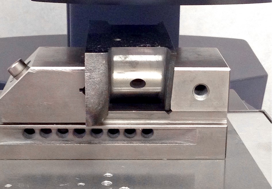
For the implemented process a Wilson VH3100 series Vickers Microhardness Tester with DiaMet software was used. Parts were clamped in a machinist vice and placed on the stage without manipulation of orientation.
Figure 1.1 – Crank pin held in machinist vice (source: Buehler)
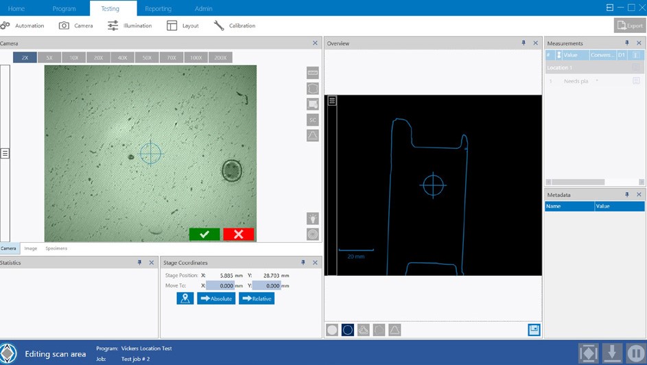
Trace function was used with the overview camera to create a template of the part to be tested; minimizing the set up time for the indent locations. The use of the template reduced the location set up time to 45 seconds in the three areas; two at forty-five degrees and one perpendicular to case.
Figure 1.2 – Trace function template for ease of indent locations (source: Buehler)
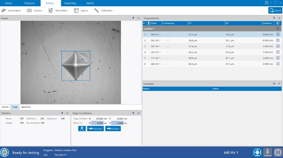
The DiaMet software snapped the template to the part at the specified location and the operators confirmed location. Observation of the set up time, making and measuring indents was 10, 50 and 40 percent respectively. Total amount of indents for a crankshaft was 216 indents on average with of time 1.25 hours with 15 minutes of operator interaction.
Figure 1.3 – Indent make and measure being performed automatically (source: Buehler)
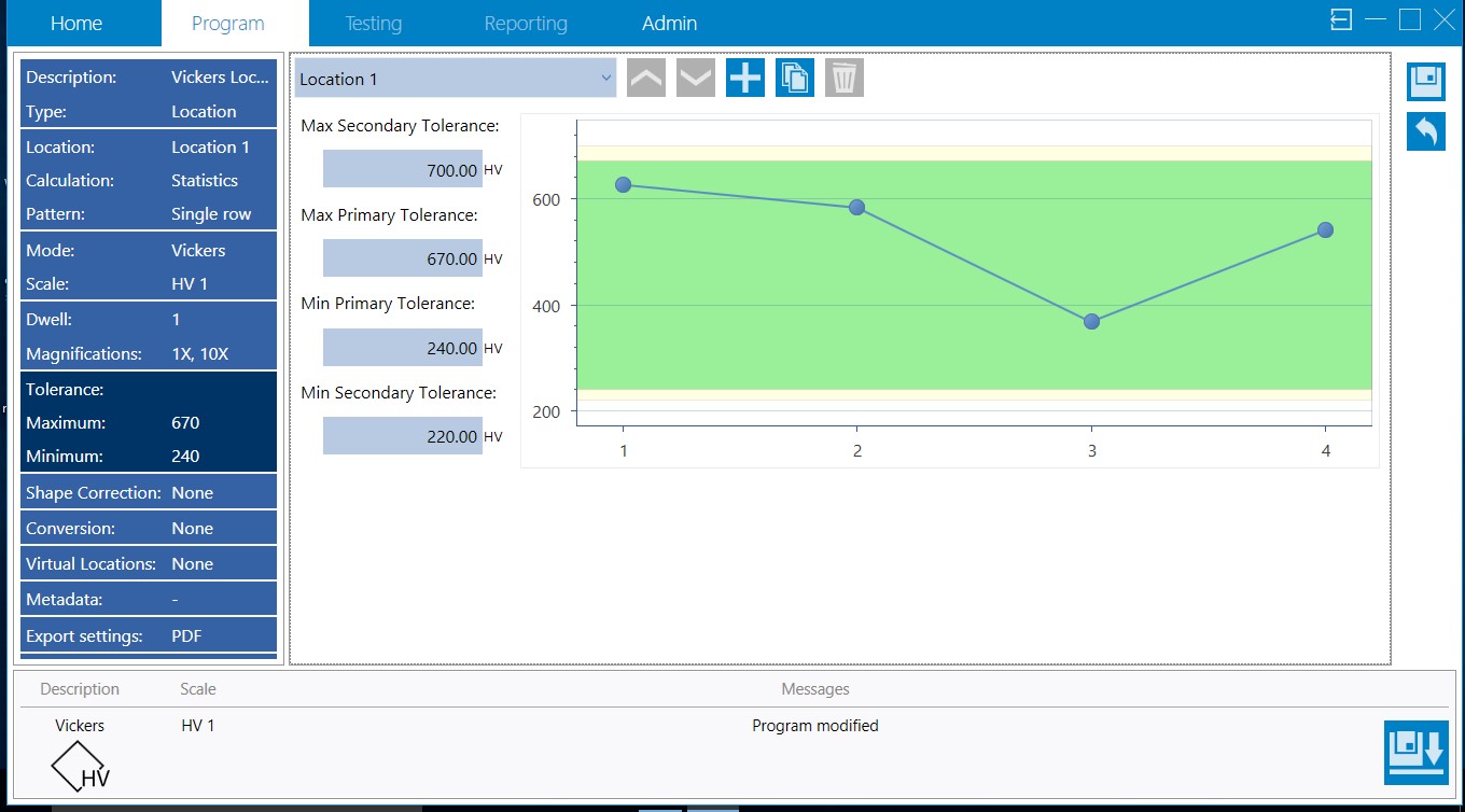
Visual high and low threshold warnings were added to each program giving the operator the ability for quick assessment of parts versus the confirmation after all crank pins and journals were analyzed as it was in previous methodology.
Figure 1.4 – Visual high low threshold warnings to alert operators of hardness thresholds (source: Buehler)
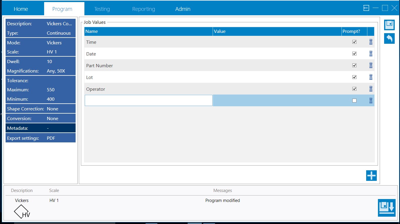
For reporting, metadata was set up to prevent operator errors in transcribing data.
The time study evaluation shows automation saves a significant amount of time with setup as well as the time required to make and measure the Vickers indents. The total amount of time that the operators spend setting the indent profile, measuring and compiling data is reduced by 86% as well as avoiding any errors in transcribing data. Repeatability of testing is increased operator to operator, as variability between operator judgement is eliminated. The combination of using trace function and templates eliminated the need for operators to spend time aligning parts on the stage as well as mitigated the risk of a misplaced indent profile. The increase of visibility of part failure is evident at time of measurement and gives the operator the ability to recheck either an area or total part without the need for extended quarantine of parts for re-examination. Using metadata fields within the Vickers testing program removed transcribing issues which would hold up batches of cranks until records could be reviewed.
Die casting can be tricky to understand; additionally, the term has become something of a catch-all phrase for a production process that covers both low- and high-end technology. In this Original Heat Treat TodayTechnical Tuesday feature, come along with Martin Reeves, Owner of Fontec-Global, LLC, as he takes readers through the die casting process, giving helpful definitions of terms and easy-to-understand descriptions of processes.
The term "die cast" is one many will have heard referring to a particular part; sometimes as a recommendation, sometimes inferring a cheaper alternative, but always as a catch-all for a production process that encompasses a whole range of technologies from cheap and cheerful to the highest technology. So here is a quick overview of what can be termed as "die casting."
(source: fontec-global, LLC)
Die/permanent mold casting has become the dominant casting process for nonferrous alloys of aluminum, magnesium, and zinc, and with the growth of aluminum as a major structural component in automotive design, it is set to maintain that position in the future. This is an overview of the various ways and processes in which permanent metal molds are used today.
Typical metals used in die-casting are lower melting point alloys of aluminum, magnesium, and zinc. Lead and pewter are also cast in this way, and the original process was developed for creating movable type around 150 years ago for the fledgling printing industry. Copper and its alloys of brass and bronze can also be cast in this way, and even some cast irons have been cast in permanent molds with suitable mold coatings as the melting/casting temperatures approach that of the mold steels used.
Many of us will probably have used the process to make lead shot, fishing weights, or toy soldiers (showing my age now) in lead, which can be melted over a candle. Likewise, we see examples of die casting that can be produced in a vast range of sizes, and with high levels of surface finish and accuracy in our everyday life. It is this versatility to produce fine detail, accurate dimensions, and fine finishes that has driven the growth and development of the high pressure machines, which can produce these castings in high volumes (40 – more than 100/hr). This has ensured its continued popularity.
When we talk about die casting, it is normally the automated process using high pressure machines that force metal into a closed die; but there are several different processes that use permanent dies, and even within the high pressure die casting industry there are now different processes in use depending on the product, alloy, and industry. The majority of technological developments in the last 20 years have been in HPDC processes with bigger machines and computer controls.
Types of Die Casting Processes
The three principal (most popular) variations on the die casting process are:
High Pressure Die Casting (HPDC)
Low Pressure Die Casting (LPDC)
Gravity or Permanent Mold Die Casting
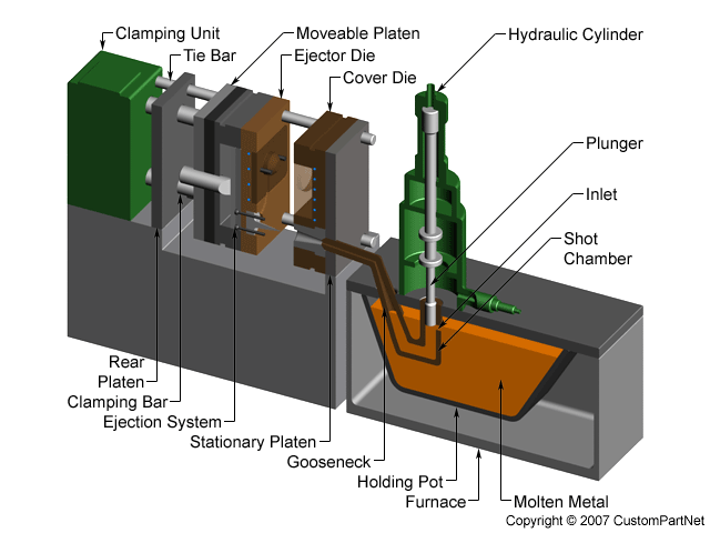
Hot Chamber Machine (source: fontec-global, LLC)
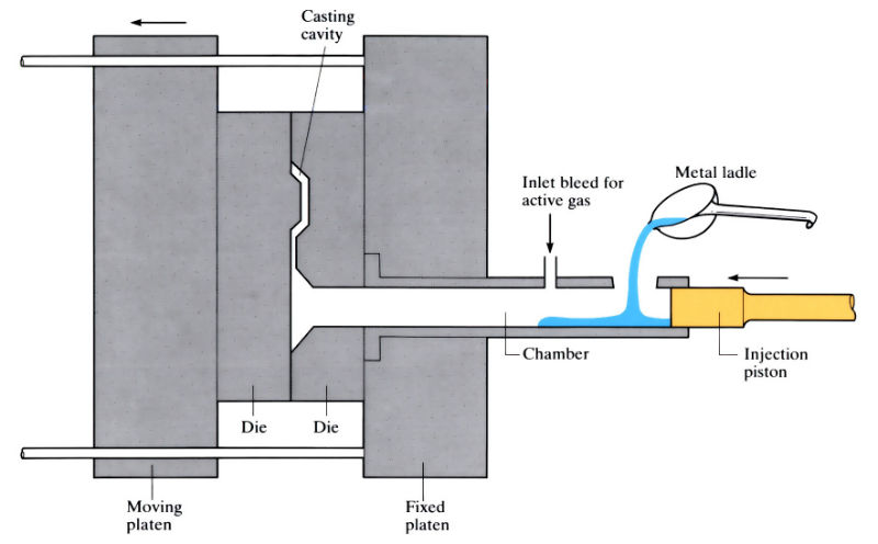
High Pressure Die Casting (HPDC) – This is now the most common form of nonferrous casting production, in which the molten metal is forced into the cavity under very high pressures. This process utilizes two different means of introducing the metal. A hot chamber machine will have the holding furnace installed as an integral part of the die casting machine, and the metal pump is immersed in the metal and forces metal directly into the cavity. Bigger and more sophisticated castings and alloys use a cold chamber process where the metal is held in a separate furnace and transferred into a shot sleeve on the machine linked to the die. It is then forced directly into the cavity by a ram.
Die Casting Machine (source: fontec-global, LLC)
All of these processes have variations that make them uniquely suited to specific types of castings or alloys. The development of novel processes and controls has expanded the scope of HPDC in recent years to the extent that safety critical structural castings can be produced and heat treated.
A historical problem with conventional die castings was the turbulence of the injection process, which caused air and gases to become trapped in the solid metal. Attempts to heat treat these castings resulted in expansion of the gases, which created blistering and eruptions on the surface and a reduction in mechanical properties. New processes, new alloys, and improved controls on die casting machines have now eliminated these issues, and thin-walled structural parts for vehicle bodies and structures are now normal production.
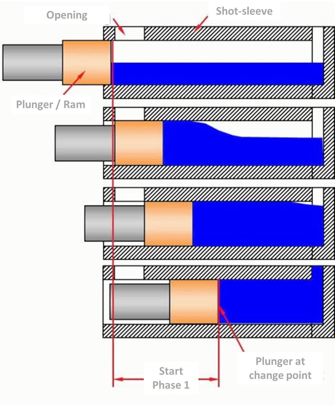
HPDC Ram Shot Control (source: fontec-global, LLC)
The development of bigger die casting machines and the evolution of shot control has expanded the scope and size of parts that can be produced. Shot control now means that instead of the ram simply moving at a steady speed to push the metal into the cavity, the movement profile can be controlled to move the metal gently at first to avoid air entrapment, and then intensifying towards the end of the stroke to ensure complete filling and improvements in metal density. When this feature is combined with vacuum assistance in the die, then the casting quality is improved dramatically, and along with newly developed alloys, can be heat treated to a T6 level for optimum properties.
Cold Chamber Machines -- These allow for the metal to be dispensed into the shot sleeve (plunger cylinder) from an outside source. The transfer can be simply with a hand ladle, an automated ladle arm or robot, or via a pump or pressurized holding furnace to achieve an accurate and repeatable mass of metal.
Over the last 20 years or so, the size of die casting machines has increased dramatically to accommodate both heavier and larger castings. The capacity of a machine is defined as the locking force that can be applied to the die platens, and this has now reached over 5,000 tons of force. This allows for larger, thin-walled parts, such as complete door frames to be cast as a single piece.
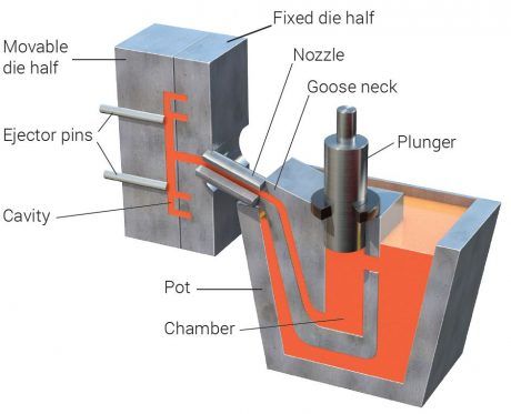
Hot Chamber (source: fontec-global, LLC)
Hot Chamber Machines -- These, on the other hand, have the holding furnace as an integral part of the die casting machine, and metal is transferred via a pump that is permanently immersed in the metal. A plunger is adjusted to push a defined amount of metal into the die for each cycle.
Because of the limitations of the furnace and immersed pump, this process is confined to smaller die casting machines and parts. Because of aluminum’s aggressive affinity for ferrous metals, this process is more often used for zinc and magnesium casting.
Vertical High Pressure Machines -- These use a similar technology to conventional horizontal machines, but the shot sleeve is vertical and is filled completely in a vertical orientation before injection, allowing a less turbulent flow of metal into the die.
Vertical machines can also use a vacuum and siphon tube system to fill the shot sleeve where the metal is sucked from the holding furnace by a vacuum in the die cavity. Like the low pressure process, it has the advantage of creating a smooth metal flow into the die while the vacuum, strong enough to suck the metal, has the added advantage of a partial degassing effect and gives better quality castings.
There are variations of High Pressure Die Casting that generally have well defined niche markets:
Semi-solid casting, also known as Thixotropic or Rheocasting, uses a similar machine; but instead of molten metal, a billet of semi-solid metal is inserted into the shot sleeve before injection into the die.
The process uses a property of aluminum alloys to be solidified in a way that retains approximately 40-60% liquid, is stable enough to be handled, but can be cut with a knife. The advantage of this process is in creating a casting with similar properties to a forging that can be heat treated and polished. The downside has been the overall cost compared to conventional castings.
Metal powder injection uses fine metal powders with a binder material instead of molten metal, and is poured into the shot sleeve in measured amounts and then introduced into the die and compacted by the plunger. The part is then sintered to remove the binder and consolidate the part. This is used for small and intricate parts where very specific alloy mixes can be created without having to melt an alloy. The process is also used for some magnesium parts overcoming the dangers associated with processing molten magnesium.
Low Pressure Die Casting (LP casting) -- This is used almost exclusively for aluminum road wheels as well as other high integrity and safety critical parts where heat treatment is also a prerequisite to achieve mechanical properties; in this process, the molten metal is forced into the die cavity by pressure in the holding furnace below the die, which raises the molten metal into the die where it is held until the narrow inlet area solidifies and the pressure is released. The smooth flow characteristics provide a high quality casting that can be heat treated.
Gravity (Permanent Mold) Die Casting is maybe the simplest of the die casting processes and can vary from a simple mold for lead shot or fishing where the molten metal is poured directly into either static or tilting molds and flows by gravity into the cavity.
Static molds are filled directly by hand or auto ladle into a split metal die. After solidification, the die is opened and the casting, with runner system, are removed.
Tilting dies are mounted on a tilting mechanism, and the metal is poured into a tundish attached to the die. After filling, the die is tilted to allow the metal to run from the tundish into the die cavity. This enables large castings to be made as the tundish can be filled fully before tilting. Castings of 100 to 300 lbs. are not uncommon, and the limit is normally the size of the die block.
An advantage of this process is the ability to use sand cores to create hollow internal shapes in castings. In gravity and low pressure die casting, the metal flow is gentle enough that sand cores can be used without breaking up and producing hard inclusions in the casting. In HPDC, the speed and turbulence of the metal entering the die is violent enough to break conventional sand cores. There are some foundries using salt cores, which are much harder, and must be dissolved from the casting. They can also create corrosion problems if not done correctly.
Centrifugal casting is used primarily in the casting of pipes and tubes in a variety of ferrous and nonferrous alloys. Molten metal is poured into a spinning tubular mold where centrifugal forces force it into an even coating on the wall of the mold, which is then cooled to create the pipe. The process is predominantly for ductile iron water distribution piping as well as engineering pipe and tube stock.
There are two basic processes used industrially--horizontally spun molds and vertically spun molds.
The horizontal process is used for longer pipes--up to 6 m (20 ft) long--with molten metal being introduced simply at one end and allowed to flow or progress along the mold length (DeLavaud process) to provide a more accurate wall thickness in the finished pipe.
The vertical process is used for smaller cylindrical parts, such as brake drums and other parts where a more dense, defect free metal structure is required. The process is confined to simpler geometries where no or simple cores can be used. Brake drums and discs would be typical parts in grey cast iron.
Direct Chill Cast Billets (source: fontec-global, LLC)
Continuous casting is a process used to continuously cast various alloys into billets, Direct Chill Casting (DCC), for further processing such as for extrusion, or to provide a continuous supply of form to be cut off and processed. The molten metal is poured into a tundish, which provides a continuous and controlled flow of metal into a water-cooled die, which moves up and down as the metal solidifies and keeps the solid metal moving downwards, making more room for new metal being poured.
Slush casting is not such a common process and is used where a hollow part is required with simple geometry and a hollow shape without the use of cores. Molten metal is poured into a mold and given enough time for a solid skin to form before any excess metal is poured out of the mold. The result is a hollow casting. Used traditionally in the art world for hollow sculptures, decorative pieces, etc., it can be used with most alloys but more often with pewter and precious metals.
Counter pressure casting (CPC) uses two separate pressure chambers, creating pressure in the holding furnace above the metal surface while equalizing this with a vacuum above the furnace and in the mold cavity. The result is to draw the molten metal into the mold cavity with the minimum of disturbance and turbulence, thus ensuring a sound casting. The metal is encouraged to solidify with water or air cooling at the in-gate area before pressures are released.
Terminology – some common terms used in the foundry industry:
- Die or Mold: the main component of die casting. The terms can vary depending on location and industry.
- Clamping force: the force exerted between the two halves of the die (the platens), which resist the hydrostatic force from the metal entering the cavity at high pressure.
- Platen: the main carrying plate on the die casting machine to which one half of the die is attached.
- Ram: the piston or plunger that is used to force the metal into the die.
- Tundish: a simple bowl arrangement that allows for metal to be accumulated before or during a casting process.
- Cores: used to create internal cavities in castings. They can be re-useable mechanical components of the die, or more often in LP and gravity they will be expendable pieces made from a resin-bonded sand.
- Holding furnace: used to hold the metal at the chosen casting temperature during casting operations. This is refilled periodically to maintain consistent production.
- Shot sleeve: connected to one half of the die and allows metal to be introduced and held prior to being injected into the die.
- Gooseneck: named for its similarity to a goose's neck, this is the pump unit that sits in the metal and supplies metal in a hot chamber machine.
Die Casting Defects – some terms that refer to common defects on die castings:
- Mis-Runs: where the metal has failed to completely fill the die cavity.
- Porosity: internal voids created by gas trapment or evolution during the solidifying process.
- Blow holes: produced as a result of moisture or contamination on the die or core surface when metal is introduced and caused by the rapid expansion of moisture.
- Inclusions: foreign matter that has become trapped in the casting, such as core sand, oxide particles, etc.
- Hot tears: when the casting strength is insufficient to withstand cooling contraction during solidification.
- Cold shuts: created when the metal entering the die is too cold and solidifies prematurely in some positions while metal is still entering the die.
- Die soldering: aluminum has an aggressive appetite for iron, and certain alloys will attack the steel dies even in the short time for die casting injection, creating adhesion of the casting.
- Heat checking: a form of thermal fatigue cracking where temperature cycling at the die surface creates fine cracks that encourage sticking and degrade the surface finish of the casting.
- Shrinkage: found in castings with heavy sections with poor connections to the main feed path of metal. The contraction to the solid state can create shrinkage depressions at the surface or internal voids.
- Laminations: where cold dies allow rapid solidification of a thin skin before final solidification of the main mass.
Roger Jones, FASM–CEO Emeritus, Solar Atmospheres (source: Solar Atmospheres)
Heat Treat Today’s Medical and Heat Treating December 2019 issue featured an article on medical alloys.Heat Treat Today asked Roger Jones, CEO Emeritus of Solar Atmospheres, Inc., to comment on how specialty medical metals are heat treated. These include titanium, niobium, tantalum, nitinol, and copper, to name a few, which in turn are used to create such standard medical devices and equipment as diagnostic guide wires, miniscule screws for implants, complex surgical tools that are operated robotically, and more. Read to see how Roger describes the hot zone and conditions under which medical device alloys are heat treated.
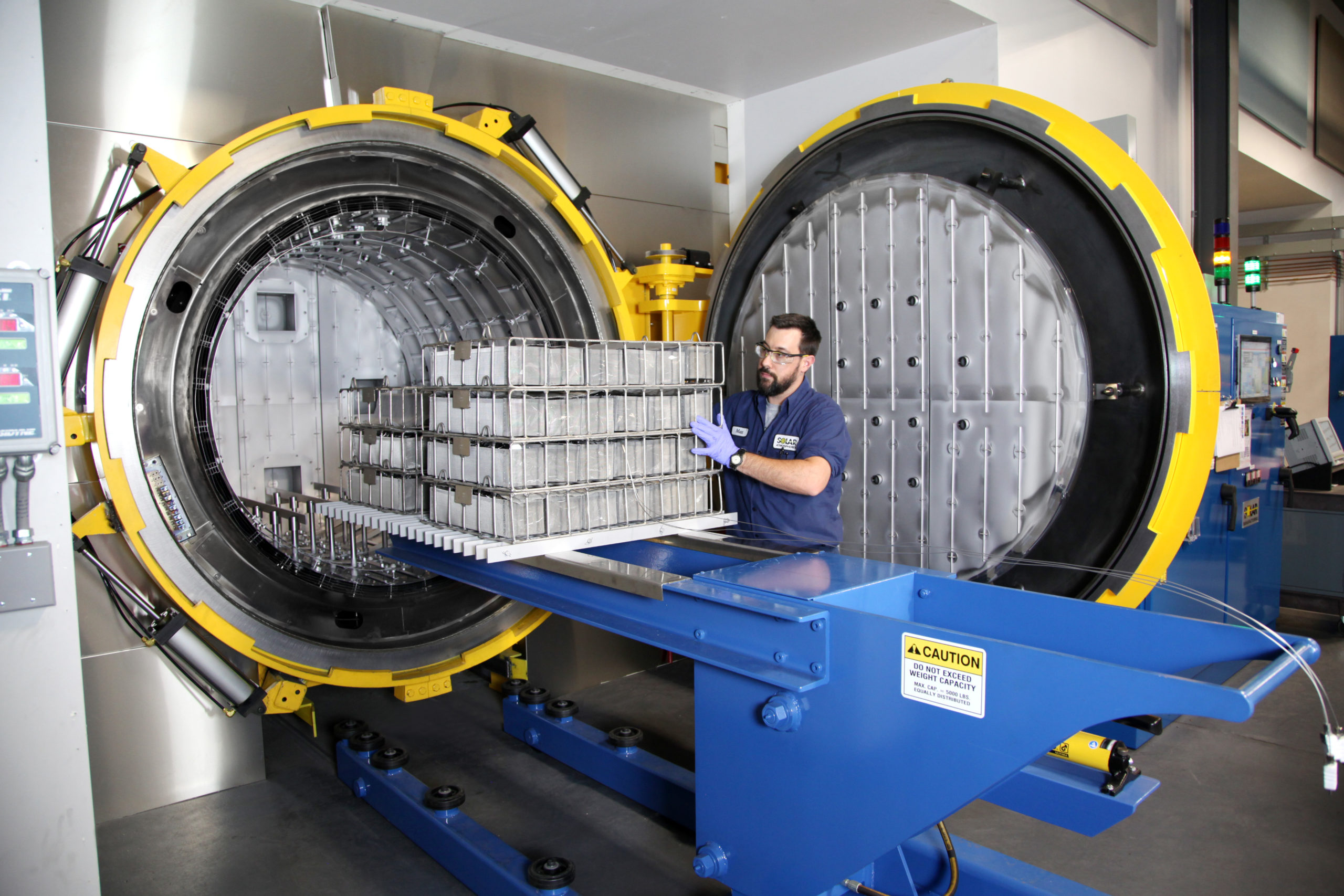
Vacuum furnace chambers processing titanium, niobium, chrome cobalt, and other medical device alloys are typically constructed from stainless steel. The hot zones are comprised entirely of metal (moly); graphite materials are never used in the construction of the hot zone or in fixturing parts. These furnaces process medical device alloys exclusively to avoid cross-contamination of the hot zone or the medical parts being treated.
Ultimate vacuum levels should be 1 X 10⁻⁶ Torr or better, with leak rates no greater than 2 microns Hg per hour. Gas system isolation valves aid in achieving tight vacuum, as they eliminate constant pumping on the quench system. Vacuum furnace leak up procedures are performed weekly, as well as a bake out at 2400 °F for one hour.
Horizontal, front-loading vacuum furnace with all-metal hot zone in a cleanroom setting typically used for heat treatment of medical alloys and devices (source: Solar Atmosphere)
Because of the alloys processed, cooling gases are mainly high purity argon from a liquid source. Very seldom is nitrogen used for cooling. Either type K or type N Inconel clad work thermocouples are imbedded in the loads for precise temperature readouts at +/- 10 °F or better. Processes include vacuum annealing, aging, stress relieving, solution treating, hardening, tempering, and other special processing. All furnaces are approved to the MedAccred quality standard, are surveyed to AMS 2750E, and comply with AS9100D in their processing parameters. Because the alloys are thermally treated, the vacuum furnaces operate in an air conditioned clean room with controlled temperatures and humidity levels.