Search Results for: valery

Dr. Valery Rudnev on Equipment Selection for Scan Hardening

Dr. Valery Rudnev On . . . 

Induction Hardening Tips: Equipment Selection for Scan Hardening


Introduction

Induction scan hardening is one of the more popular techniques for strengthening various steels, cast irons, and powder metallurgy components. This scanning method is be used to harden flat surfaces or irregular shapes (e.g., rails, bumpers, bed-ways, support beams, track shoes for earth moving machines, teeth of large gears, etc.); however, it is most frequently used for hardening outside and/or inside surfaces of cylindrically shaped components, such as shafts, pins, raceways, etc. In scan hardening, the inductor or workpiece or both moves linearly relative to each other during the hardening cycle.

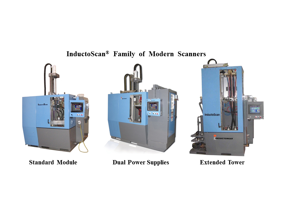
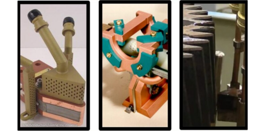
Depending on the workflow of parts, the induction system can be built as vertical, horizontal, or even at an angle, though vertical scan hardening is by far the most popular design. As an example, Figure 1 shows three variations of the InductoScan® family of modular vertical scan hardening systems.

Figure 1. Variations of the InductoScan® family of vertical modular scan hardening systems. (Courtesy of Inductoheat, Inc.)

What to Choose: Vertical Scanners vs. Horizontal Scanners

Both vertical and horizontal induction scanning systems are viable means to heat treat components. The decision of whether to use a vertical or horizontal scan hardening system is usually based upon the shape and length of heat treated parts, as well as the available space and a workflow throughout the plant or factory in which the equipment is to be installed. Horizontal hardening is often chosen when long workpieces are to be processed (typically 4ft/1.2m or longer) or when high production rates are needed for processing shorter parts.

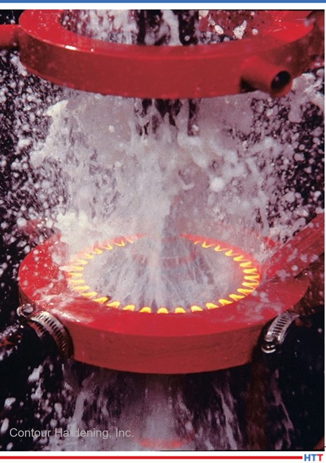
Vertical scanners are typically associated with a smaller footprint. In the majority of applications, the cylinder-shaped workpiece (e.g., shafts) is positioned between centers or some other tooling or fixture. The workpiece may rotate inside the inductor to even out the hardening pattern around the circumference, or it may be located preferentially with respect to the inductor and processed without rotation when hardening workpieces of certain shapes. The quench spray typically impinges the part approximately 12mm (½”) to 40mm (1.5”) from the coil heating face and is angled away to prevent the quench from splashing back into the inductor. This dimension can vary with different types of steel, the scan rates, and the design specifics.

Setting Up Scan Hardening Systems

Vertical systems can be set up to process as many as four shafts at a time depending on the size of the shafts being processed and the available power source. Parts are loaded either manually or automatically onto a lower center. A loading assist “vee” block or nest may be used to steady the part as it is being loaded and processed. For larger parts, pneumatic cylinders lift the upper centers to facilitate loading. With vertical scan hardening, it may take an appreciable amount of time to process the workpiece because it must be loaded, scanned along the length up to the position where the heating process commences, fast scanned back down to the load-unload position, and then unloaded.

In contrast, a horizontal system is typically set up as a single continuous scanning line that allows parts to be loaded from a magazine and continuously fed to the exit of the machine. Depending on the specific heating requirements for the end of the component, parts are fed end-to-end through the heating coil and pass on to the next process. The loading system can push parts through the inductor by a pinch drive mechanism, conveyor, mechanical pushers, or other means, such as skewed rollers [1]. On a horizontal system, due to heavy duty roller support underneath, gravity, and any required stabilizing devices on top of the workpiece, the part is maintained in the center of the induction coil and quench ring. There is usually less risk of distortion than that which occurs with a vertical system where the part’s shape can change or warp if the part is not always centered.

However, during the heating process on a horizontal system, it may be more difficult to maintain the exact location of features of the part since it is commonly free rolling on the skewed rollers. For this reason, consideration should be given to a part’s shape, the symmetry of its positioning in respect to the heating coil, and selection of support devices. When horizontal systems are used for heat treating long parts of appreciable weight, it might be challenging to speed up or slow down the progress of the workpiece along the skewed rollers as quickly as might be done in vertical scanners with a servo-driven carriage that captures the part.

The roller system of horizontal scan hardeners can interfere with achieving symmetrical cooling of the workpiece since the location of the rollers and the rotation detection mechanism on shorter parts may be too close to the coil or quench barrel. Additionally, a stabilizing fixture may be required to prevent lighter and smaller workpieces from being moved axially by electromagnetic forces rather than the roller system. As with the vertical system, some type of rotation detection must be employed to ensure that the part is actually rotating as it is passing through the heating coil.

Quenching Challenges

Quenching presents a challenge with horizontal scanning [1]. When scanning vertically, quenching takes place below the inductor, which naturally allows gravity to pull the quench fluid down, therefore, the quench fluid continues to flow on the part long after it has passed the quench chamber, which is beneficial to achieving circumferential uniformity of quenching as well as reaching temperatures suitable for handling. When quenching horizontally, the effect of gravity is different and the way the quenchant falls from the workpiece varies leading to the probability of non-uniform cooling along the circumference of the heat-treated component (e.g., quenchant may run along the top of the part but fall off the bottom).

It is also more critical for horizontal scanners to maintain a sufficient distance between the inductor exit and the quenching device due to the higher probability of the liquid quenchant splashing back into the inductor. This could lead to irregular results caused by different cooling rates affecting the hardness consistency as well as the magnitude and distribution of residual stresses.

All of these factors can be summarized as follows:

  • The main process differences between vertical or horizontal scan hardening systems lie in the part handling and quenching subtleties.
  • With some scanners, splash shields, deflectors, and drip trays may be needed to prevent the backsplash of the quench fluids.

Maximizing Process Flexibility of Induction Scanners

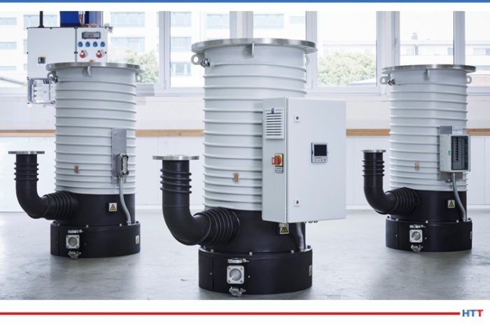
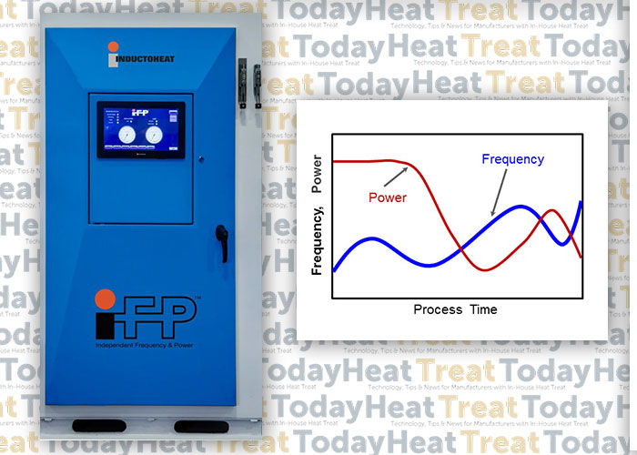
It is commonly assumed that all scan hardening systems exhibit high process flexibility with respect to the workpiece length and, to some extent, variations in the diameter of the part. Conventional scan hardening provides the ability to vary the speed and power during the process, which controls the amount of heat applied to different areas of the part. Recently developed Statipower-IFP® inverter technology (Figure 2) extends the capability of conventional induction hardening systems to instantly and independently adjust not only power and scan rate but also frequency (5kHz to 60kHz range) during scan hardening cycle [2].


Figure 2. Statipower-IFP® inverter allows instant and independent adjustment of frequency (5kHz to 60kHz) and power during scan hardening cycle. (Courtesy of Inductoheat Inc.).

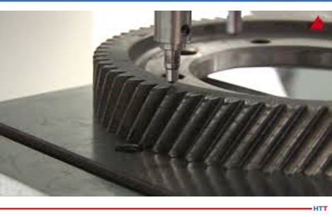
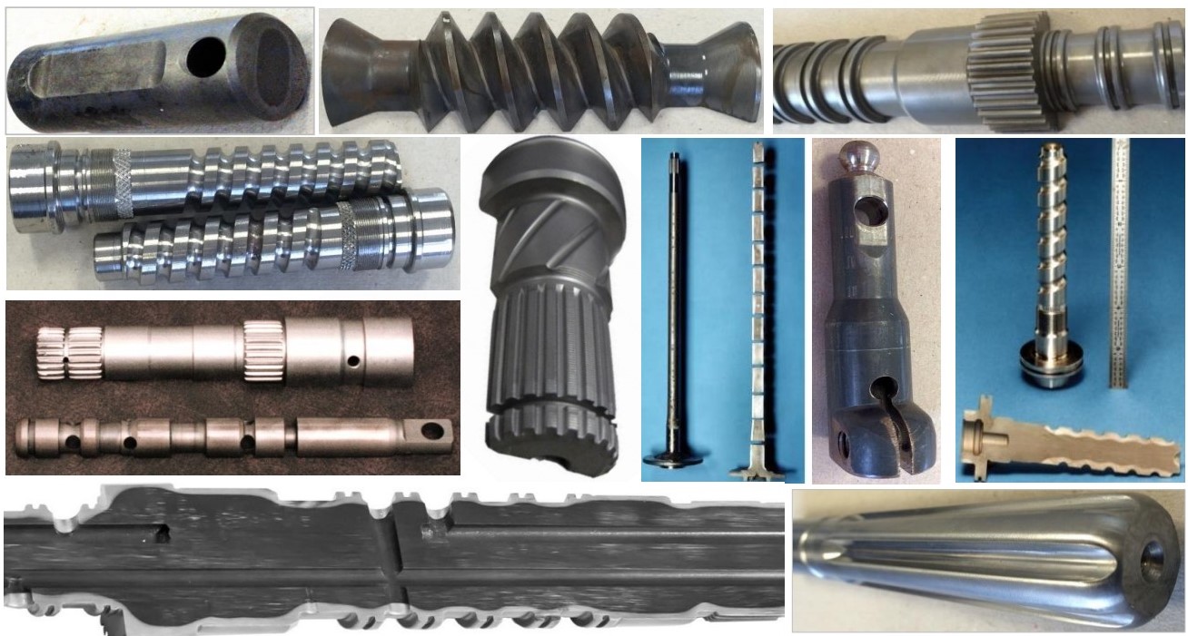
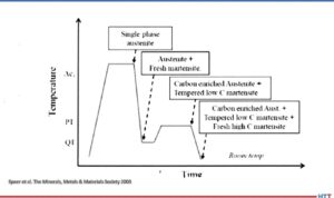
In the past, the flexibility of induction scanners was limited to using power supplies with single operational frequency. However, when processing a family of parts or components with numerous geometrical irregularities (including large diameter changes, multiple holes, sharp shoulders, combinations of solid and hollow areas, various required case depths, etc., see Figure 3), the fixed frequency in conventional induction scanners can be inadequate, producing “hot” and “cold” spots, as well as unwanted microstructures (e.g., local grain boundary liquation and grain coarsening).


Figure 3. A family of components exhibiting numerous geometrical irregularities

Single frequency scanners have been used to tweak the process in an attempt to promote or suppress thermal conduction [1,2], resulting in a compromise in achieving the desired metallurgical quality, production rate, and process capability. In the heating stage, compromise affects the ability to provide heat-appropriate austenization, but it also presents challenges in the quenching stage.

Austenization is followed by a quenching stage (spray or immersion). If the available, fixed frequency of a conventionally designed induction scanner is considerably higher than optimal then the depth of heat it generates (current penetration depth) is smaller than needed, which might not be sufficient in establishing necessary austenization. In this case, to reach sufficient austenization, the scan rate and applied power must be reduced to allow thermal conduction to the required subsurface depth. Unfortunately, a noticeable heat surplus might still occur.

An Example of Compromised Results

As an example, Figure 4 shows the computer modeling results of the induction scan hardening of a hollow medium carbon steel shaft that has diameter changes, a chamfer, and a groove. Nominal outside diameter is 0.05m (2”); nominal inside diameter is 0.02m (3/4”). Because the shaft is symmetrical, only the top half was modeled. Temperature variations at four selected areas of the shaft are monitored at different inductor positions. Frequency was constant at 15 kHz.

The scan rate and coil power were varied during hardening as an attempt to accommodate changes in the shape of the shaft.

Figure 4. Dr. Valery Rudnev on Equipment Selection for Scan Hardening  on Vimeo.

Reducing scan speed (in some cases substantially) not only adds unnecessary cycle time, but if the scan speed is too slow, certain regions of a heat-treated component may cool below the critical temperature before it enters the quench zone, resulting in an undesirable formation of mixed structures and upper transformation products, as well as reduced or spotty hardness readings.

If the fixed frequency of a conventionally designed scanner is noticeably lower than optimal, it may produce a deeper than required austenized layer, affecting hardness depth, transition zone and creating excessive distortion. In this case, increasing scan rate and power density should minimize, but not eliminate, this outcome. Such a compromise can still affect local spray quenching producing undesirable metallurgical results.

Conclusion

It is important to remember that applied frequency has the greatest impact on depth of induction heat generation. A new generation of Statipower-IFP® inverters (Figure 2) eliminates these drawbacks by optimizing the metallurgical quality of induction scan hardening, expanding process flexibility and maximizing a production rate. This patented technology can be effectively used in both vertical and horizontal induction scanners. Reports [2] show changing both coil power and frequency during scan hardening can reduce peak temperatures on 70oC (125oF) while maintaining the required hardness pattern.

I recommend Reference #1 to readers interested in further discussion on induction scan hardening subtleties.


References

  1. Rudnev, D.Loveless, R.Cook, Handbook of Induction Heating, 2nd Edition, CRC Press, 2017.
  2. Doyon, V.Rudnev, C.Russell, J.Maher, Revolution-not evaluation-necessary to advance induction heat treating, Advance Materials & Processes, September 2017, p.72-80.


______________________________________________

Dr. Valery Rudnev, FASM, is the Director of Science & Technology, Inductoheat Inc., and a co-author of Handbook of Induction Heating (2nd ed.), along with Don Loveless and Raymond L. Cook. The Handbook of Induction Heating, 2nd ed., is published by CRC Press. For more information click here.

Dr. Valery Rudnev on Equipment Selection for Scan Hardening Read More »

Induction and Sustainability Tips Part 4: Vacuum Furnace and Heat Treat Energy Savings

Discover expert tips, tricks, and resources for sustainable heat treating methods Heat Treat Today’s recent series. Part 4, today’s tips, covers induction heating, quench, and insulation tips. We’ve added resources towards the end of today’s post for further enrichment.

This Technical Tuesday article is compiled from tips in Heat Treat Today’s May Focus on Sustainable Heat Treat Technologies print editionIf you have any tips of your own about induction and sustainability, our editors would be interested in sharing them online at www.heattreattoday.com. Email Bethany Leone at bethany@heattreattoday.com with your own ideas!


1. Tips for Induction Hardening


Contact us with your Reader Feedback!

What are the benefits of induction hardening? Here are a few:

  • Saves space: Induction hardening requires minimum space required in comparison with furnaces
  • Saves energy: Induction heating equipment does not need to be kept running when not in use
  • Clean: Induction heating equipment requires no combustion gases
  • Energy-efficient: Only a small proportion of the material needs to be heated
  • Minimize deformation: Induction hardening requires no applied force
  • Save maintenance costs: Inductor coils have a long life, reducing the need for maintenance

Source: Humberto Torres Sánchez, Chief Metallurgist, ZF Group

#induction hardening #deformation #zerocombustiongas

2. Insulation = Key for Energy Savings in Vacuum Furnaces

Look for insulation quality in your next vacuum furnace.
Source: NITREX

Improvements in insulation materials are also contributing to greater energy efficiency of vacuum furnaces. Most furnaces on the market today have a 1” (25.4 mm) graphite board with bonded Grafoil and two layers of graphite felt. However, the insulation performance of a 1” (25.4 mm) graphite board is about 25% less efficient than a 1” (25.4 mm) graphite felt. For processes that require high operating temperatures, typically over 2,200°F (1,204°C), an all graphite felt that is 2” or 2.5” thick (50.8 mm or 63.5 mm) minimizes heat loss inside the hot zone. Efficiency gains of up to 25% are possible over the standard 1” (25.4 mm) board and 1” (25.4 mm) graphite felt insulation and an even greater gains at higher operating temperatures. To safeguard the graphite felt from mechanical harm and localized compression, these thicker all-graphite felt insulation configurations are usually covered with a carbon fiber composite (CFC) sheet about 0.050” (1.27 mm) thick.

Source: NITREX

#insulation #energysavings #graphite

3. Thinner Steel, Lighter Car

Fuel efficiency (and the stringent requirement for passenger safety) has raised the bar for the automotive industry to procure steel with high strength, hardness, and ability to fabricate. Reduction of weight requires lighter cars with thinner body material which can absorb impact. These dual contradictory properties of high hardness material which can be easily shaped can normally be achieved either by heat treat or through addition of alloys. These two processes are described below.

Normal heat treatment to produce small grains in the material will increase the hardness in steel but also create a propensity to fracture. Thus, a process known as quench and partition — where carbon diffusion from martensite to retained austenite to stabilize the latter — has been introduced. Further verification and prediction of the phases has been conducted using thermodynamics modeling for phase characteristics by Behera & Olsen at Northwestern University, Materials Science and Engineering.

The process starts with full automatization (or in some cases intercritical annealing) followed by fast quench to a defined quench temperature (QT) between the martensite start, Ms, and martensite finish, Mf, temperature. The steel is then reheated to the partition temperature (PT) and held there for a certain partition time followed by a quenching step again to room temperature, as shown in the image.

Quench and partition process
Source: Speer et al. The Minerals, Metals, & Materials Society 2003

The quenching step establishes the largely martensite matrix while the partition step helps stabilize the retained austenite by carbon partitioning. During the holding step, carbon diffuses from martensite to retained austenite and thus improves its stability against subsequent cooling or mechanical deformation. The final microstructure consists predominantly of tempered martensite and stabilized retained austenite with possibly a small amount of bainite formation and carbide precipitation during the partition step and fresh martensite formation during final quenching.

The other process to achieve high hardness and high ductility is by alloy addition in carbon steel. Over, 2,000 different types of steel exist. A new type of steel that is extremely strong, but simultaneously ductile is used in the automotive industry. Small quantities of elements like vanadium or chrome in steel promotes ductility. They are not brittle; however, up until now they have not been strong enough to enable the construction of car bodies with thinner sheets.

In the crystals of steels, the atoms are more or less regularly arranged. Steels become particularly ductile though if they can switch from one structure to another. This is because this process allows energy absorption, which can then no longer initiate any damage in the material. In a car body or other steel components, tiny areas then alternate with the two different atom arrangements.

Ductile steels have two coexisting crystal structures. The search produced an alloy made from 50% iron, 30% manganese and 10% respectively of cobalt and chrome (Max Planck Institutes).

Source: Madhu Chatterjee, PresidentAAT Metallurgical Services LLC

#quenchandpartition #quenchtemp

4. Tips for Selecting Induction Heating Equipment

“The following factors typically influence equipment design:

  • Material
  • Prior microstructure
  • Part geometry
  • Austenitizing temperature
  • Production rate
  • Power requirements, kW (typically selected by vendor based on information provided)
  • Frequency selection, kHz (typically selected by vendor based on information provided)
  • Pattern/profile (i.e., shape of heating area)
  • Coil design (typically selected by vendor based on information provided)
  • Process-development requirements
  • Application-specific criteria (e.g., water vs. polymer quenching)
  • Method of loading and unloading the workpiece (e.g., manual or robotic)
  • Stock removal after heat treatment
  • Type of tempering (i.e., furnace/oven vs. induction)”

SourceDan Herring, The Heat Treat Doctor®, Atmosphere Heat Treatment, vol. 1, 2014, pp. 656.

#inductionequipment #inductiondesign

5. Additional Resources on Induction Heating, Quench, and Insulation

Read more about the processes when you click on these articles:


Find heat treating products and services when you search on Heat Treat Buyers Guide.com


Induction and Sustainability Tips Part 4: Vacuum Furnace and Heat Treat Energy Savings Read More »

Complex Geometries – A Simple Heat Treat Reality

What makes the geometry of a part “complex”? With the increasing use of AM and 3D printing for parts along with typically complex parts, heat treaters in many industries must acquire the equipment and technical know-how for precise applications.

This Technical Tuesday article is compiled from Heat Treat Today articles and industry news releasesEmail Bethany Leone at bethany@heattreattoday.com or click the Reader Feedback button below to chime in on the topic.


What Are Complex Geometries?


Contact us with your Reader Feedback!

Complex geometries in industrial parts are often defined by their intricate patterns and structures, which entail specialized heat treat processing. As Inductoheat describes in a case study with Stellantis, “Many times, complex geometries of components are linked to intricate hardness patterns and specific requirements for magnitude and distribution of residual stresses.”

Heat Treat Equipment for Processing Parts with Complex Geometries

Be it for highly customized medical implants or for engine components in the burgeoning electric vehicle industry, complex geometries need to heat treated carefully. Fasteners in the medical device industry can be quite intricate and susceptible to creep or other dimensional changes; one method heat treating these parts — particularly titanium alloy parts — would be in a vacuum furnace. In vacuum and in hot isostatic presses, the environment allows for complex geometries that are 3D printed to be made into a unified whole piece. “Heat conduction can be carefully monitored [in induction heating coils] to confirm that an overheat condition does not occur at the target temper areas,” making induction a key candidate for heat treating your parts with complex geometries (“Tempering: 4 Perspectives — Which makes sense for you?“). To accommodate the complexities of certain parts, designing an induction coil for the desired case hardening may entail simulation to “[predict] coil heating, which altogether results in a longer coil lifetime,” (“Simulation Software and 3D Printers Improve Copper Coils”). For more on induction coils, check out this article by Dr. Valery Rudnev.

Suffice it to say, there is a great diversity of heat treatment options to explore when it comes to identifying the appropriate equipment for your application.

What Processes Are Used in Heat Treating Complex Geometries?

Perhaps you have all of your equipment needs necessary for heat treating your parts with complex geometries. Are you completing your heat treat processing in the most technically sound manner? Check out the following excerpts that speak to processing complex geometries.

“[Forging] at elevated temperatures enables reaching high strains and forming complex geometries in a single stroke. Additionally, thermal and mechanical influence during the forging can lead to improving local mechanical properties and the quality of the resulting joining zone.” (“Thermomechanical Processing for Creating Bi-Metal Bearing Bushings“)

“In some cases, such attempts result in a component’s geometries that might be prone to cracking during heat treating or might be associated with excessive distortion . . . .  The subject of induction hardening of complex geometry parts (including but not limited to gears, gear-like and shaft-like parts, raceways, camshafts, and other critical components) is also thoroughly discussed, describing inventions and innovations that have occurred in the last three to five years.” (“Heat Treat Training Benefits Stellantis“)

LPC [low pressure carburizing] with gas quenching can be an attractive option for distortion prone complex geometries as the cooling rates are slower than oil quenching; however, given the slower cooling rate, it becomes very important to choose a higher alloyed steel that will achieve the desired hardness.” (“Elevate Your Knowledge: 5 Need-to-Know Case Hardening Processes“)

Complex Geometries In the News

See how your peers are solving complex geometries needs in these real-life partnerships with industry suppliers. From additive manufacturing (AM) and precision manufacturing parts to heat treat technology, maybe your company is next to leverage manufacturing equipment to “wow” the industry.


Find heat treating products and services when you search on Heat Treat Buyers Guide.com

Complex Geometries – A Simple Heat Treat Reality Read More »

10 pasos para solucionar las fallas en un equipo de inducción

OC

Nikola Tesla afirmó: <<Si quieres descubrir los secretos del universo, concéntrate en la energía, la frecuencia y la vibración.>>

Al revisar los mecanismos internos de un sistema de inducción es posible evidenciar cada uno de estos tres elementos. Los 10 pasos de esta guía servirán para apoyar a los operadores de departamentos internos de tratamiento térmico en entender los secretos de la inducción para así identificar posibles escollos en tales sistemas y dar solución a problemas comunes que se puedan presentar.

This original content article was first written by Alberto Ramirez, engineer of Power Supply and Automation at Contour Hardening, Inc. and an honoree from Heat Treat Today’s 40 Under 40 Class of 2021, for Heat Treat Today's May 2023 Sustainable Heat Treat Technologies print edition. Read the Spanish version below, or click the flag above right for the English version.

Puedes hacerlos llegar a Bethany Leone al correo bethany@heattreattoday.com


Alberto Ramirez
Power Supply and Automation Engineer
Contour Hardening, Inc.

Contact us with your Reader Feedback!

Los metales pueden calentarse mediante el proceso de inducción electromagnética, mediante el cual un campo magnético alternativo cerca de la superficie de una pieza de trabajo metálica (o conductora de electricidad) induce corrientes de Eddy (y, por lo tanto, calentamiento) dentro de la pieza de trabajo.

Los sistemas de inducción pueden llegar a ser sistemas complejos que tienen como objetivo endurecer piezas o secciones específicas de un componente mecánico, dependiendo del grado de complejidad de la pieza a tratar; para el profesional, el desafío será el diagnóstico de los problemas que se lleguen a presentar.

1. Familiarízate con el proceso

Figura 1. Proceso de endurecimiento por inducción
Source: Contour Hardening, Inc.

El proceso de inducción envuelve muchas características tales como: posición de la pieza dentro de la bobina de inducción, posiciones de carga, posiciones de enfriamiento, tiempos de ciclo, potencia eléctrica aplicada, entre otras. Es importante que el profesional sea capaz de identificar la falla y la situación particular en el momento en el que se está presentando.

En algunas ocasiones las fallas no son evidentes y, por ende, es indispensable analizar la pieza que ha sido tratada; este análisis puede ser clave para entender situaciones tales como: falta de profundidad de capa por potencia eléctrica o disminución en la frecuencia de salida, entre otros posibles escenarios.

Adicional al análisis de la pieza, es vital inspeccionar la “escena del crimen” ya que muchos de los sistemas de inducción, dada la naturaleza del proceso y el peligro que implica manejar altos potenciales eléctricos, suelen ser en extremo automatizados y las estaciones de trabajo de difícil acceso para el personal, así que una buena estrategia de trabajo consiste en observar detenidamente las condiciones generales del equipo para determinar el punto de inicio para la resolución del problema.

2. Identifica los componentes principales de tu sistema de inducción, así como los mecanismos de seguridad para ciertas zonas en particular

Entender la interrelación del sistema es importante para comprender qué elemento realiza cierta acción, así como los canales de comunicación entre ellos. Una vez que se genere este conocimiento, se puede asociar una falla a un componente en particular. Usualmente los sistemas de inducción se componen de los siguientes elementos:

Figura 2. Componentes de un sistema de inducción
Source: Contour Hardening, Inc.

Como mencionamos con anterioridad el proceso implica altos potenciales eléctricos, y para eso la naturaleza de las fuentes de alimentación involucra dispositivos electrónicos de potencia, como capacitores eléctricos, los cuales almacenan energía y, por ende, es importante descargar eléctricamente el sistema antes de comenzar a inspeccionar un equipo.

3. Ten preparadas las herramientas necesarias para realizar un buen análisis del problema

Figura. Capacitores
Source: Contour Hardening, Inc.

Al igual que cualquier problem técnico, el uso de la herramienta mecánica es indispensable al realizar algún tipo de proyecto, pero para el diagnóstico de una falla en un equipo de inducción es importante contar con:

  • Osciloscopio
  • Generador de funciones
  • Amperímetro
  • Multímetro digital y analógico.
  • Sondas de alto voltaje

Sin estos elementos es muy difícil llegar a un diagnóstico fiable, y  la posibilidad de encontrar la falla es mínima. Por ende, tener estos medidores en buen estado y, sobre todo, calibrados nos da una perspectiva más clara del problema.

4. Verifica que los sensores del proceso, los monitores de energía y las bobinas de inducción funcionen correctamente

Existen distintos medidores que recogen información acerca del proceso; esta información en su mayoría puede ser visualizada a través del HMI (Human Machine Interface), y, en muchas ocasiones, una buena manera de comenzar a entender el problema es recopilar la información del proceso. Si los medidores no funcionan correctamente, te pueden llevar a conclusiones erróneas.

Verifica que los medidores de energía estén funcionando correctamente, así como tus señales de entrada y de salida.

Las bobinas de inducción son un elemento clave en el proceso de inducción ya que acorde a su geometría generan los campos magnéticos adecuados para lograr los resultados metalúrgicos esperados. Si existen fugas de agua o los elementos de transmisión eléctrica se encuentran sueltos o sucios, seguramente podrán ser la raíz del problema. Es importante comenzar a realizar el diagnóstico de la falla una vez se haya descartado este circuito en particular.

Figura 4. Ejemplo de parámetros de energía
Source: Contour Hardening, Inc.

5. Realiza estudios de energía constante en tu subestación para identificar posibles problemas en tu suministro de energía, así como tiempos críticos

La energía eléctrica es la fuente principal en un proceso de inducción; las fuentes de alimentación transforman y potencializan este recurso para crear campos electrónicos lo suficientemente fuertes para generar el calor en la pieza.

Por ende, es importante descartar con evidencia que el problema en cual nos encontramos no se debe a una falla del sistema eléctrico del cual nuestro sistema de inducción forma parte. De igual manera entender cómo se comporta nuestro sistema eléctrico nos puede ayudar a generar patrones de comportamiento que puedan determinar la solución en momentos específicos en los que se lleguen a presentar.

6. Trabaja de forma metódica documentando tus movimientos y realiza un paso a la vez

Los sistemas de inducción pueden ser muy intimidantes si no has tenido experiencia previa, y, al igual que con cualquier elemento o situación, es importante abordar de manera lógica el problema analizando el modo de la falla, identificando las partes principales que interactúan en ese preciso momento, y, a partir de este análisis, documentar y realizar pequeños pasos, uno a la vez, ya que, de no ser así, es muy probable que pierdas todo el trabajo realizado y la situación empeore.

Figura 5. Antes y durante un arco eléctrico dentro de la línea de transmisión
Source: Contour Hardening, Inc.

Si los movimientos no son exitosos, siempre puedes regresar a tu punto de partida e intentar otro acercamiento. La idea consiste en que el modo de la falla se mantenga estable sin importar los movimientos realizados hasta que se resuelva el problema. De esta manera lograrás contener la falla; de otra manera podrías estar dañando otros elementos sin darte cuenta.

Es muy importante entender que los procesos son secuencias que anteceden y preceden a nuevos eventos; si entiendes el proceso y, una vez resuelto el problema, ahora tienes una nueva falla, es importante analizar si esta falla es la continuación del proceso ya que, de ser así, es posible que te encuentres frente al caso de un evento que está desencadenado una serie de fallas y se haga necesario practicar un análisis más profundo. La idea general es llegar a la raíz del problema y mitigar el riesgo.

7. Intenta cualquier posibilidad relacionada con el proceso sin importar que la relación entre ésta y el problema no sea directa

Un pensamiento lógico puede resolver la mayoría de las fallas técnicas de un sistema, pero, para fallas excepcionales, es necesario utilizar la imaginación y agotar todos los recursos posibles ya que el área de interés más insignificante o el lugar menos pensado puede ser la clave para resolver un problema.

8. Conoce tus fuentes de alimentación

Uno de los factores claves en cualquier equipo de inducción son sus fuentes de alimentación. Las fuentes de alimentación son equipos que no requieren un mantenimiento tan arduo en comparación con otros sistemas en la industria, pero, de no presentarse las condiciones mínimas de mantenimiento, pueden generar altas pérdidas para la organización.

Figura 6. Diagrama de flujo del proceso eléctrico en una fuente de alimentación
Source: Contour Hardening, Inc.

En los casos en los que el problema se encuentra en las fuentes de alimentación, es vital que se siga el mismo proceso metódico previamente descrito. Entender cómo funciona el proceso de transformación de la energía te dará una ventaja, al igual que conocer los componentes empleados o el tipo de tecnología utilizado en el proceso de rectificación, en la inversión (estado sólido o tubos de electrones) y en el circuito resonante. Generalmente las fuentes de alimentación siguen el siguiente patrón de transformación (Figura 6).

9. Identifica las partes críticas de tu equipo de inducción y prepara un inventario de éstas

Figura 7. Daño en una bobina de inducción
Contour Hardening, Inc.

Usualmente los componentes que forman parte de las fuentes de alimentación son difíciles de conseguir dependiendo de la antigüedad de tu equipo, y con la reciente crisis de microchips en el mercado, existen tiempos de entrega muy largos para los elementos de control y automatización; de igual manera, los precios de los mismos se han disparado. Por ende, es vital que exista una lista de partes críticas y un inventario de éstas.

Adicionalmente a los elementos descritos, las bobinas de inducción suelen ser elementos muy característicos e importantes en el proceso de inducción. Éstas bobinas son elementos complejos que han sido diseñados exclusivamente para la pieza, por lo que su fabricación puede tomar varias semanas, y es importante tomar las precauciones necesarias para mantener un movimiento de mantenimiento constante.

10. Realiza mediciones preventivas al sistema para generar un patrón de comportamiento

Figura 8. Ejemplo de posibles mediciones
Contour Hardening, Inc.

Cuando el sistema se encuentre trabajando en óptimas condiciones, genera un plan de medición el cual te permita recopilar información de puntos específi cos dentro del sistema. Una vez que se vuelva a presentar una nueva falla puedes comparar las mediciones de falla contra las del buen funcionamiento. Algunos ejemplos de mediciones pueden ser:

  • Temperatura
  • Voltaje
  • Corriente eléctrica
  • Resistencia y capacitancia
  • Formas de onda

En resumen

Una metodología de trabajo ordenada y documentada, un buen catálogo de piezas de recambio, junto con las herramientas de trabajo necesarias, pueden ser elementos clave para entender un problema y, lo que es más importante, resolverlo de forma eficaz.

Es vital que los profesionales se capaciten de manera constante para mejorar los tiempos de paro debido a fallas en los sistemas de inducción. La capacitación relacionada con procesos metalúrgicos sería una buena forma de complementar tus habilidades de resolución de problemas permitiéndote interpretar las características de los sistemas de inducción, al igual que de los elementos que los componen.


Bibliografía

Valery Rudnev and George Totten, ed., ASM Handbook Volume 4C: Induction Heating and Heat Treatment, (Materials Park, OH: ASM International Heat Treating Society, 2014), 581- 583


Sobre el autor: Alberto C. Ramirez es ingeniero en Mecatrónica egresado del Instituto Tecnológico Nacional de México Campus León con una maestría en Administración de Tecnologías de la Información por el Instituto Tecnológico de Monterrey. Cuenta con más de 8 años de experiencia en fuentes de alimentación, gestión de proyectos, mantenimiento y automatización. Actualmente se desempeña como ingeniero de fuentes de alimentación y automatización en Contour Indianapolis. Alberto inició su carrera en la fi lial de Contour en México y debido a su dedicación forma parte del staff en los Estados Unidos.

He is also an honoree from Heat Treat Today's 40 Under 40 Class of 2021.

Para más información:

Contacta a Alberto escribiendo a: aramirez@contourhardening.com.


Find heat treating products and services when you search on Heat Treat Buyers Guide.com


10 pasos para solucionar las fallas en un equipo de inducción Read More »

10 Steps To Troubleshoot Your Induction System

OC

Nikola Tesla said, “If you want to find the secrets of the universe, think in terms of energy, frequency, and vibration.” These three components are evident in getting to know the inner workings of an induction system. When it comes to troubleshooting such a system at in-house heat treat departments, this 10 step guide will help heat treat operators understand the secrets of induction and solve common problems that may arise.

This original content article was first written by Alberto Ramirez, engineer of Power Supply and Automation at Contour Hardening, Inc. and an honoree from Heat Treat Today’s 40 Under 40 Class of 2021, for Heat Treat Today's May 2023 Sustainable Heat Treat Technologies print edition.


Alberto Ramirez
Power Supply and Automation Engineer
Contour Hardening, Inc.

Contact us with your Reader Feedback!

Metals can be heated by the process of electromagnetic induction, whereby an alternative magnetic field near the surface of a metallic (or electrically conductive) workpiece induces eddy current (and thus heat) within the workpiece. Induction systems can be complex systems that aim to heat treat specific parts or sections of a mechanical component; depending on the degree of complexity of the part to be treated, it will be the challenge of a professional to detect any problem.

1. Familiarize Yourself with the Process

Figure 1. Induction hardening process
Source: Contour Hardening, Inc.

The induction process involves many characteristics such as: position of the piece within the induction coil, load positions, cooling positions, cycle times, applied electric power, and others. It is important that the professional can identify the failure and the particular situation at the moment in which it is occurring.

On some occasions, the failures are not evident and therefore it is essential to analyze the part that has been treated. This analysis can be key to understanding situations such as poor depth due to electrical power or decrease in output frequency, among other possible scenarios.

In addition to the analysis of the piece, it is vital to inspect the “crime scene,” since many of the induction systems — given the nature of the process and the danger involved in handling high electrical potentials — are usually highly automated and the work stations are difficult for staff to access. A good work strategy consists of carefully observing the general conditions of the equipment to determine where the problem will begin to be solved.

2. Identify Main Components and Certain Security Mechanisms of Your Induction System

Understanding the interrelationship of the system is important to comprehend which element performs a certain action, as well as the communication channels between them. Once this knowledge is generated, a failure can be associated with a particular component. Induction systems are usually made up of the elements in Figure 2.

Figure 2. Induction system components
Source: Contour Hardening, Inc.

As we mentioned before, the process involves high electrical potentials, and for this reason, the nature of the power supplies involves power electronic devices such as electrical capacitors, which store energy. Therefore, it is important to electrically discharge the system before beginning to inspect a piece of equipment.

3. Have the Necessary Tools Ready To Carry Out a Good Analysis of the Problem

Figure 3. Capacitors
Source: Contour Hardening, Inc.

Like any technical problem, the use of a mechanical tool is essential when carrying out some type of project, but for the diagnosis of failure in induction equipment it is important to have:

  • Oscilloscope
  • Function generator
  • Ammeter
  • Digital and analog multimeter
  • High voltage probes

Without these elements it is exceedingly difficult to reach a reliable diagnosis, and the possibility of finding the fault is minimal. Therefore, having these meters in good condition and above all, calibrated, gives a clearer perspective of the problem.

4. Verify that the Process Sensors, Power Monitors, and Induction Coils Are Working Properly

There are different meters that collect information about the process. This information can mostly be viewed through the HMI (human machine interface). On many occasions, a good way to begin to understand the problem is by collecting the information on the process. If these meters do not work correctly, they can lead you to wrong conclusions.

Verify the energy meters are working correctly, as well as your input and output signals.

Induction coils are a key element in the induction process since, according to their geometry, they generate the appropriate magnetic fields to achieve the expected metallurgical results. If there are water leaks or the electrical transmission elements are loose or dirty, it could be the root cause of the problem. It is important to start troubleshooting once this circuit is ruled out.

Figure 4. Energy parameters example
Source: Contour Hardening, Inc.

5. Carry Out Studies of Constant Energy in Your Substation To Identify Possible Problems in Your Energy Supply, Including Critical Times

Electrical energy is the main source in an induction process, power supplies transform and potentiate this resource to create electronic fields strong enough to generate heat in the piece.

Therefore, it is important to find evidence that rules out failures of the electrical system that the induction system is a part of. In the same way, understanding how our electrical system behaves can help us generate behavior patterns that can determine the solution at specific times when it may arise.

6. Document Your Work Methodically and Take One Step at a Time

Induction systems can be very intimidating if you have not had previous experience, and, like any element or situation, it is important to logically approach the problem by analyzing the failure mode, identifying the main parts that interact at that specific moment. From there, document and take small steps, one at a time. If you don’t, it is very likely you will lose all the work you have done, and the situation will get worse.

Figure 5. Before and after of an arc at the transmission line
Source: Contour Hardening, Inc.

If the moves are unsuccessful, you can always return to your starting point and try another approach. The idea is that the failure mode remains the same no matter what moves you make until the problem is resolved. In this way you will have the failure contained, otherwise you could be damaging other elements without realizing it.

It is very important to understand that the processes are sequences that precede and proceed new events. If you understand the process and solve a problem, but now have a new failure, it is important to analyze if this failure is the continuation of the process. If so, it is possible that you find yourself in a case where an event is triggering a series of failures. Therefore, a more in-depth analysis must be carried out. The idea to generate is to get to the root cause and mitigate the risk.

7. Try Any Possibility Related to the Process Regardless of Whether the Relationship Between It and the Problem Is Not Direct

Logical thinking can solve most of the technical failures of a system. For exceptional failures, however, it is necessary to use your imagination and exhaust all possible resources, since the smallest area of interest or the least thoughtful place can be the key to solving a problem.

8. Get To Know Your Power Supplies

One of the key factors in any induction equipment is its power supplies. Power supplies are equipment that do not require such arduous maintenance compared to other systems in the industry, but if the minimum maintenance conditions are not present, they can generate high losses for the organization.

Figure 6. Flow diagram of the energy process at the power supply
Source: Contour Hardening, Inc.

In cases where the problem is the power supplies, it is vital that the same methodical process previously described is followed. Understanding how the energy transformation process works will give you an advantage, as will knowing the elements that compose them or the type of technology used in the rectification process, in the inversion (solid state or electron tubes) and in the resonant circuit. Generally, power supplies follow the transformation in Figure 6.

9. Identify the Critical Parts of Your Induction Equipment and Prepare an Inventory

Figure 7. Coil damage
Contour Hardening, Inc.

Usually, the elements that belong to the power supplies are difficult to obtain depending on the age of your equipment. With the recent microchip crisis in the market, control and automation elements have very long delivery times or the prices are very high. Therefore, it is vital that there is a list of critical parts and an inventory of these.

In addition to the elements described, induction coils are usually very characteristic and important elements in the induction process. These coils are complex elements that have been designed exclusively for the piece, so their manufacture can take several weeks, and the necessary precautions must be taken to maintain a constant maintenance movement.

10. Perform Preventative Measurements to the System To Generate a Pattern of Behavior

Figure 8. Possible examples of measurements
Contour Hardening, Inc.

When the system is working in optimal conditions, generate a measurement plan which allows you to generate information on specific points within the system. Once a new failure occurs again you can compare the measurements of failure against those of good performance. Some examples of measurements can be:

  • Temperature
  • Voltage
  • Current
  • Resistance and capacitance
  • Waveforms

Summary

An orderly and documented work methodology, a good spare parts catalog, and the necessary work tools can be key elements to understand a problem and, more importantly, to solve it effectively.

It is vital that professionals are in continuous training in order to decrease downtime due to failures in induction systems. Training related to metallurgical processes would be a good way to complement your resolution skills by being able to interpret the characteristics of induction systems with the elements that compose it.


References

Valery Rudnev and George Totten, ed., ASM Handbook Volume 4C: Induction Heating and Heat Treatment, (Materials Park, OH: ASM International Heat Treating Society, 2014), 581- 583.


About the Author: Alberto C. Ramirez graduated from the National Technical Institute of Mexico as a mechatronics engineer. He earned his master’s degree in information technology administration from Monterrey Institute of Technology. With more than eight years of experience in power supplies, project management, maintenance, and automation, he currently works as a Power Supply and Automation Engineer at Contour Indianapolis. Alberto began his career at the Contour subsidiary in Mexico and due to his dedication, he is part of the staff in the United States. He is also an honoree from Heat Treat Today's 40 Under 40 Class of 2021.

For more information:

Contact Alberto at Contact Alberto at aramirez@contourhardening.com.


Find heat treating products and services when you search on Heat Treat Buyers Guide.com


10 Steps To Troubleshoot Your Induction System Read More »

Contributor and Friend of Heat Treat Today Was Selected for ASM’s 2022 William Hunt Eisenman Award

op-edDr. Valery Rudnev was recently selected to be the American Society for Metal's (ASM) William Hunt Eisenman Award. Dr. Rudnev has many years of experience in the heat treat industry, particularly in induction heating. He is quite a mover and a shaker in the industry with more than 40 years involvement with his work and publications. He has even come to be known as "Professor Induction".


Dr. Valery Rudnev was recently selected for ASM's William Hunt Eisenman Award winner “for dedicated service to the global materials science community, leadership, development and promotion of induction heating and heat treating technologies and novel technologies.” The award was established by ASM Int’l in 1960 in recognition of unusual achievements in industry in the practical application of materials science and engineering through production or engineering use.

Contact us with your Reader Feedback!

Over the years, Dr. Rudnev has close professionals ties with Heat Treat Today authoring a popular multi-installment exclusive column “Dr. Valery Rudnev on …”. He has published eleven articles in Heat Treat Today including:

During his career, Dr. Rudnev has authored and co-authored numerous chapters and articles for many handbooks devoted to various aspects of induction heating, heat treating, metallurgical aspects, computer modeling and innovative process development. His credits include a great deal of “know-how”, more than 60 patents and inventions (U.S. and International) and more than 300 engineering/scientific publications

In October of 2021, Dr. Valery Rudnev retired from his professional activity and now he is focusing on his Christian faith, family and hobbies.

Heat Treat Today sincerely congratulates Dr. Valery Rudnev with this well-deserved award and wish him all the best in his retirement.


Find heat treating products and services when you search on Heat Treat Buyers Guide.com


Contributor and Friend of Heat Treat Today Was Selected for ASM’s 2022 William Hunt Eisenman Award Read More »

The Chemistry Behind the Process: 6 Heat Treat Tips for Brazing, Induction, and Quenching

OCWe’ve assembled some of the top 101 Heat Treat Tips that heat treating professionals submitted over the last three years into today’s original content. If you want more, search for “101 heat treat tips” on the website! Today’s tips will remind you of the importance of materials science and chemistry.

By the way, Heat Treat Today introduced Heat Treat Resources last year; this is a feature you can use when you’re at the plant or on the road. Check out the digital edition of the September Tradeshow magazine to check it out yourself!


Induction Hardening Cast Iron

Induction hardening of cast irons has many similarities with hardening of steels; at the same time, there are specific features that should be addressed. Unlike steels, different types of cast irons may have similar chemical composition but substantially different response to induction hardening. In steels, the carbon content is fixed by chemistry and, upon austenitization, cannot exceed this fixed value. In contrast, in cast irons, there is a “reserve” of carbon in the primary (eutectic) graphite particles. The presence of those graphite particles and the ability of carbon to diffuse into the matrix at temperatures of austenite phase can potentially cause the process variability, because it may produce a localized deviation in an amount of carbon dissolved in the austenitic matrix. This could affect the obtained hardness level and pattern upon quenching. Thus, among other factors, the success in induction hardening of cast irons and its repeatability is greatly affected by a potential variation of matrix carbon content in terms of prior microstructure. If, for some reason, cast iron does not respond to induction hardening in an expected way, then one of the first steps in determining the root cause for such behavior is to make sure that the cast iron has not only the proper chemical composition but matrix as well.

(Dr. Valery Rudnev, FASM, Fellow IFHTSE, Professor Induction, Director Science & Technology, Inductoheat Inc.)


14 Quench Oil Selection Tips

Here are a few of the important factors to consider when selecting a quench oil. 

  1. Part Material – chemistry & hardenability 
  2. Part loading – fixturing, girds, baskets, part spacing, etc. 
  3. Part geometry and mass – thin parts, thick parts, large changes in section size 
  4. Distortion characteristics of the part (as a function of loading) 
  5. Stress state from prior (manufacturing) operations 
  6. Oil type – characteristics, cooling curve data 
  7. Oil speed – fast, medium, slow, or marquench  
  8. Oil temperature and maximum rate of rise 
  9. Agitation – agitators (fixed or variable speed) or pumps 
  10. Effective quench tank volume 
  11. Quench tank design factors, including number of agitators or pumps, location of agitators, size of agitators, propellor size (diameter, clearance in draft tube), internal tank baffling (draft tubes, directional flow vanes, etc.), flow direction, quench elevator design (flow restrictions), volume of oil, type of agitator (fixed v. 2 speed v. variable speed), maximum (design) temperature rise, and heat exchanger type, size, heat removal rate in BTU/hr & instantaneous BTU/minute.
  12. Height of oil over the load 
  13. Required flow velocity through the workload 
  14. Post heat treat operations (if any) 

(Dan Herring, “The Heat Treat Doctor®”, of The HERRING GROUP, Inc.)


How to Achieve a Good Braze

In vacuum brazing, be certain the faying surfaces are clean, close and parallel. This ensures the capillary action needed for a good braze.

A good brazing filler metal should:

  1. Be able to wet and make a strong bond on the base metal on which it’s to be applied.
  2. Have suitable melt and flow capabilities to permit the necessary capillary action.
  3. Have a well-blended stable chemistry, with minimal separation in the liquid state.
  4. Produce a good braze joint to meet the strength and corrosion requirements.
  5. Depending on the requirements, be able to produce or avoid base metal filler metal interactions.

(ECM USA)


Pay Attention to Material Chemistry

When trying to determine a materials response to heat treatment, it is important to understand its form (e.g., bar, plate, wire, forging, etc.), prior treatments (e.g. mill anneal, mill normalize), chemical composition, grain size, hardenability, and perhaps even the mechanical properties of the heat of steel from which production parts will be manufactured. The material certification sheet supplies this basic information, and it is important to know what these documents are and how to interpret them.

Certain alloying elements have a strong influence on both the response to heat treatment and the ability of the product to perform its intended function. For example, boron in a composition range of 0.0005% to 0.003% is a common addition to fastener steels. It is extremely effective as a hardening agent and impacts hardenability. It does not adversely affect the formability or machinability. Boron permits the use of lower carbon content steels with improved formability and machinability.

During the steelmaking process, failure to tie up the free nitrogen results in the formation of boron nitrides that will prevent the boron from being available for hardening. Titanium and/or aluminum are added for this purpose. It is important, therefore, that the mill carefully controls the titanium/nitrogen ratio. Both titanium and aluminum tend to reduce machinability of the steel, however, the formability typically improves. Boron content in excess of 0.003% has a detrimental effect on impact strength due to grain boundary precipitation.

Since the material certification sheets are based on the entire heat of steel, it is always useful to have an outside laboratory do a full material chemistry (including trace elements) on your incoming raw material. For example, certain trace elements (e.g. titanium, niobium, and aluminum) may retard carburization. In addition, mount and look at the microstructure of the incoming raw material as an indicator of potential heat treat problems.

(Dan Herring, The Heat Treat Doctor®)


Aqueous Quenchant Selection Tips

Determine your quench: Induction or Immersion? Different aqueous quenchants will provide either faster or slower cooling depending upon induction or immersion quenching applications. It is important to select the proper quenchant to meet required metallurgical properties for the application.

  1. Part material: Chemistry and hardenability are important for the critical cooling rate for the application.
  2. Part material: Minimum and maximum section thickness is required to select the proper aqueous quenchant and concentration.
  3. Select the correct aqueous quenchant for the application as there are different chemistries. Choosing the correct aqueous quenchant will provide the required metallurgical properties.
  4. Review selected aqueous quenchant for physical characteristics and cooling curve data at respective concentrations.
  5. Filtration is important for aqueous quenchants to keep the solution as clean as possible.
  6. Check concentration of aqueous quenchant via kinematic viscosity, refractometer, or Greenlight Unit. Concentration should be monitored on a regular basis to ensure the quenchant’s heat extraction capabilities.
  7. Check for contamination (hydraulic oil, etc.) which can have an adverse effect on the products cooling curves and possibly affect metallurgical properties.
  8. Check pH to ensure proper corrosion protection on parts and equipment.
  9. Check microbiologicals which can foul the aqueous quenchant causing unpleasant odors in the quench tank and working environment. If necessary utilize a biostable aqueous quenchant.
  10. Implement a proactive maintenance program from your supplier.

(Quaker Houghton)


Container Clarity Counts!

Assure that container label wording (specifically for identifying chemical contents) matches the corresponding safety data sheets (SDS). Obvious? I have seen situations where the label wording was legible and accurate and there was a matching safety data sheet for the contents, but there was still a problem. The SDS could not be readily located, as it was filed under a chemical synonym, or it was filed under a chemical name, whereas the container displayed a brand name. A few companies label each container with (for instance) a bold number that is set within a large, colored dot. The number refers to the exact corresponding SDS.

(Rick Kaletsky)


Check out these magazines to see where these tips were first featured:

The Chemistry Behind the Process: 6 Heat Treat Tips for Brazing, Induction, and Quenching Read More »

NLMK Group Awards Decarburization and Coating Line

HTD Size-PR LogoVIZ-Stal (NLMK Group) awarded an order for a decarburization and coating line (DCL) for its plant in Ekaterinburg, Russia to an international furnace provider for sustainable solutions in the metals industry. The company expects that the DCL will start production by the end of 2021.

International heat treat plant provider with locations in North America, Tenova received the VIZ-Stal (NLMK Group) contract through its company Tenova LOI Thermprocess, an industrial furnace plant provider based in Essen. Through the cooperation between this competence center, which specializes in heat treatment furnaces, as well as Tenova Italimpianti, the competence center for strip processing, the new line will provide one of the important stages of grain-oriented (GO) electrical strip production. Steel final processing will be carried out at a newly-built plant located in India.

Peter Wendt
Vice President
Tenova LOI Thermprocess
prozesswaerme.net

The contract includes the engineering, the supply and supervision services of mechanical and process equipment, the furnace system, and the related electrical, measuring, and control systems for the DCL.

"We are very pleased for this new order which confirms the reliability of the leading Tenova technology and underlines our strategic partnership with NLMK and VIZ-Stal," said Peter Wendt, vice president of Tenova LOI Thermprocess. "The NLMK Group is one of our most faithful clients with more than ten orders over the past fifteen years. The new DCL Line will ensure the highest surface and best magnetic properties required by the market."

"NLMK selected Tenova on the basis of the large number of references for similar heat treatment lines," explained Valery Shevelev, general director of Silicon Production at NLMK Group. “The short execution time is another important factor that led us to choose Tenova as partner for this project."

NLMK Group Awards Decarburization and Coating Line Read More »

Tips #13 – 23 – 33 – 43

One of the great benefits of a community of heat treaters is the opportunity to challenge old habits and look at new ways of doing things. Heat Treat Today’s 101 Heat Treat Tips is another opportunity to learn the tips, tricks, and hacks from some of the industry’s foremost experts.

Heat Treat Today’s latest round of 101 Heat Treat Tips is featured in Heat Treat Today 2020 fall issue (also featuring the popular 40 Under 40).

Today’s selection includes four tips from Leybold Vacuum USA, Young Metallurgical Consulting, Dr. Valery Rudnev, and Chiz Bros. Increase output, decrease production costs, hit target temperature, and avoid thermal shock with these four tips.


Heat Treat Tip #13

New Diffusion Pump Technology Increases Production Output

Gain immediate positive net cash flow with a lease to own finance option by upgrading your diffusion pumps with the new immersion heater technology. The new style heater will extend oil life and reduce energy consumption. New heater technology can increase production by eliminating the need of dropping your pump every time you change oil for faster maintenance turn around. Drop in place pump design with improved performance.

NEW-DIJ Diffusion Pumps with smart heater technology by Leybold Vacuum
Source: Leybold Vacuum USA

(Leybold Vacuum USA)


Heat Treat Tip #23

Inspection Mistakes That Cost

Rockwell hardness testing requires adherence to strict procedures for accurate results.  Try this exercise to prove the importance of proper test procedures.

  • A certified Rc 54.3 +/- 1 test block was tested three times and the average of the readings was Rc 54 utilizing a flat anvil.  Water was put on the anvil under the test block and the next three readings averaged Rc 52.1.
  • Why is it so important that samples are clean, dry, and properly prepared?
  • If your process test samples are actually one point above the high spec limit but you are reading two points lower, you will ship hard parts that your customer can reject.
  • If your process test samples are one point above the low spec limit but you are reading two points lower, you may reprocess parts that are actually within specification.
  • It is imperative that your personnel are trained in proper sample preparation and hardness testing procedures to maximize your quality results and minimize reprocessing.

Properly preparing a hardness sample can save time and money.

Source: Young Metallurgical Consulting

(Young Metallurgical Consulting)


Heat Treat Tip #33

Not Able to Hit Target Temperature — What To Do

Situation: Customer had an available 100kW/1kHz inverter and needed to heat 1-in.-diameter carbon steel bar to hot working temperature (2000°F). It was a low production application and cycle time was not critical. However, regardless of the heat time and irrespective of using maximum available output power, it was not possible to reach required target temperature. Actually, after reaching about 1470o°F there was no noticeable temperature rise regardless of increased heat time.

Solution: Severe eddy current cancellation was responsible for a failure to reach target temperature. The use of frequencies 6 kHz and greater can easily help to accomplish the goal. As a simple “rule-of-thumb,” in order to provide an efficient heating and avoid eddy current cancellation in through heating applications (e.g., through hardening or hot working), it is necessary to choose a frequency that will guarantee that the “bar diameter-to-penetration depth” ratio exceeds 3.6 at a target temperature.

(Dr. Valery Rudnev, FASM, Fellow of IFHTSE/Professor Induction/Director Science & Technology, Inductoheat Inc., An Inductotherm Group company)


Heat Treat Tip #43

Brick to Fiber to Avoid Thermal Shock

Thermal shock is a regular issue with hard refractory and brick-lined furnaces due to the constant changes in temperature for batch annealing. Switching an old furnace over to ceramic fiber is an easy process that can save time and money.

(Chiz Bros)


Tips #13 – 23 – 33 – 43 Read More »

Take a Tip or Two

One of the great benefits of a community of heat treaters is the opportunity to challenge old habits and look at new ways of doing things. Heat Treat Today’s 101 Heat Treat Tips is another opportunity to learn the tips, tricks, and hacks from some of the industry’s foremost experts.

Heat Treat Today’s latest round of 101 Heat Treat Tips is featured in Heat Treat Today fall issue (also featuring the popular 40 Under 40).

Today’s selection includes tips from Dr. Valery Rudnev, Grammer Vacuum Technologies, Inc., and L & L Special Furnace Co., Inc. This selection includes tips related to induction heating, vacuum furnaces, and temperature uniformity.


Heat Treat Tip #3

Avoid Axle Shaft Cracks After Induction Tempering

Situation: In induction scan hardening of axle shafts, there was NO cracking occurred after scan hardening (case depth varies from 5 mm to 8 mm). Cracks appeared in the spline region after induction tempering.

Solution: Most likely, the cause of this problem is associated with a reversal of residual stress distribution during induction tempering. Reduce coil power for tempering and increase time of induction tempering. Multi-pulse induction tempering applying lower power density might also help. As an alternative, instead of modifying temper cycle, you can also try to reduce quench severity by increasing the temperature of the quenchant and/or its concentration.


(Dr. Valery Rudnev, FASM, Fellow of IFHTSE, Professor Induction, Director Science & Technology, Inductoheat Inc., An Inductotherm Group company)


Heat Treat Tip #26

TZM Moly Grids

Source: Grammer Vacuum Technologies, Inc.

A very commonly observed failure mechanism with a moly post hearth assembly is bending of the moly posts. They will stay fairly straight at the center of the hearth area, but they can distort badly toward the outer sides of the work zone. The outer rows of vertical posts end up leaning away from each other. This is due to the very high linear thermal expansion coefficient of nickel-iron alloy grids (usually 330 SS or Inconel). With a high load on the nickel alloy grid, it is not able to slide on the perpendicular hearth beams as the temperature rises. The outer hearth post rows are forced in an outward direction. The quenching of the furnace load does not reverse all of this effect and over time results in the severe bending of the hearth posts.

By replacing the stainless steel or nickel alloy grids with a moly or TZM alloy moly grid, which exhibits very low thermal expansion, the hearth life can be increased. For comparison, the figure shows the coefficients of linear thermal expansion for commonly used grid materials. For example, a 36” wide 330 SS grid at 70°F grows to 36.6” wide at 2200°F.

Another significant benefit of TZM moly grids is use at higher furnace process temperatures without the problem of a softened, sagging grid that cannot support the load properly.

Source: Grammer Vacuum Technologies, Inc.


(Grammer Vacuum Technologies, Inc.)


Heat Treat Tip #41

Ways to Increase Temperature Uniformity in Heat Treat Furnaces

  1. A (sometimes) simple way to increase uniformity in a furnace is to add a circulation fan. Circulation fans can be a quick way to add an additional 5°F tighter uniformity on a batch furnace application.
  2. Be sure that the furnace is tuned optimally to reduce/eliminate any overshoot and oscillation around setpoint.
  3. Eliminate any thermal lag by making sure that the control thermocouple and TUS thermocouples have similar sensitivity. If not, the control thermocouples can fall behind and cause the TUS thermocouples to overshoot and fail.


(L & L Special Furnace Co., Inc.)


Take a Tip or Two Read More »