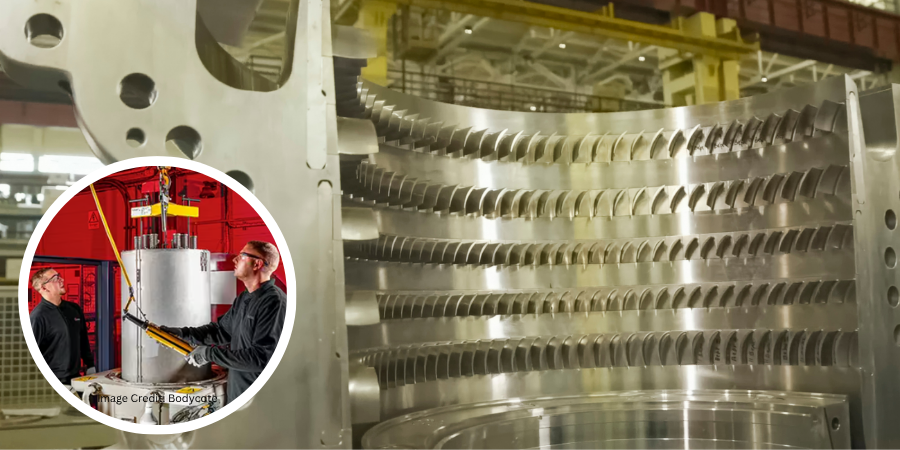
Bodycote, a global commercial heat treater serving manufacturers across North America and Europe, is expanding its hot isostatic pressing (HIP) and thermal processing capabilities to support growing demand from the aerospace and defense sectors. The expansion adds HIP equipment and powder metallurgy capabilities designed to increase processing capacity for critical, high-performance components.
More than €20 million is being invested at Bodycote’s Magny-Cours facility in France, one of the company’s European hubs for hot isostatic pressing. HIP combines high temperature with isostatic gas pressure to eliminate internal porosity and improve the mechanical properties of critical metal components.
The investment includes the installation of multiple large-format HIP vessels designed to increase available processing volume, allowing larger components to be treated while improving capability and energy efficiency. Once fully operational by the end of 2026, the expanded installation will provide Magny-Cours with multiple HIP units to support increased production across the aerospace, industrial gas turbine (IGT), and defense sectors. The expansion is also expected to create additional employment opportunities at the site.
Bodycote has also expanded HIP capacity at its Haag-Winden facility in Germany with the addition of two HIP vessels. The site specializes in both hot isostatic pressing and the company’s Powdermet product fabrication process, enabling near-net-shape components ot be manufactured and HIP processed on-site while also providing standalone HIP services for client-supplied parts.
Heidi McNary President, Global Aerospace, Defence and Energy Bodycote
“The new and upgraded sites will help deliver increased capacity for thermal processing at a time when demand from aerospace and defense [clients] is growing at a double-digit annual rate,” said Heidi McNary, president of Global Aerospace, Defence and Energy at Bodycote. The company plans to discuss the expanded capabilities with clients during the Farnborough International Airshow, scheduled for July 20–24.
Press release is available in its original form here.
Heat Treat Today publishes twelve print magazines annually and included in each is a letter from the publisher, Doug Glenn. This letter from the June 2026 Sixth Annual Buyers Guide Issue print edition examines the property-rights tensions AI raises for publishers.
In early May of this year, leaders from the North American magazine publishing industry met in Chicago for a day and a half of industry talk and “saw sharpening.” Publishers of notable magazines like Fast Company, Inc., and Farm Journal attended as did Heat Treat Today. Two main topics dominated the event: events and artificial intelligence (AI). Conspicuously absent from the discussion was any emphasis on digital publishing (see last month’s Publisher’s Page for more on the contraction of digital media growth).
The conversations about AI were interesting but non-conclusive. In a nutshell, no one, not even the publishing “experts”, had any idea where AI was headed and what impact it would have on the publishing industry. Doomsday and utopian speculations abounded side-by-side. Either could be right; no one knows.
Private Property and Permission to Use
There are real and unique issues with AI and the publishing industry. Imagine what would happen to your business if every time you produced a product, an unrelated third party would access all the details of your products and make them publicly known to whoever wants to know without getting approval from you. And, of course, you would get no compensation for all the information accessed and disseminated by this third party. All your engineering drawings, vendor lists and purchasing specs, your proprietary designs, and perspectives would all be laid bare for unfettered, uncompensated use by an unrelated third party. I’m guessing you would scream “foul” and would do what you could to protect your property from unauthorized use.
Fortunately, for many of you, your product details are not splashed openly in excruciating detail on your website. For publishers, however, websites are one of our main distribution channels (albeit secondary to our print editions). For publishers, editorial content is our product, and by and large, it is available for public consumption, but not to help others make money without prior permission.
The issue seems to be one of private property and the use of that property without prior permission. When a magazine publishes an article, it is the property of the magazine and cannot be legally reproduced in part or in its entirety without prior written approval from the publishing company. As it currently stands, those wishing to access the content can have free access to it (unless it’s behind a paywall or registration wall), but they must come to the publisher’s website, which is of financial benefit to the publisher. If the public can get access to the publisher’s content without coming to their website, the publisher loses the financial benefit of traffic to their website. This is a real and tangible financial loss and is the result of someone accessing the content without due compensation to the publisher.
It is a unique situation that publishers are facing…thankfully for you! AI companies might object by saying that they give attribution to the sources of their findings and are therefore allowed to use the content. Citations help, but providing a footnote to the source of an AI answer is similar to a pawn shop listing the location of where they stole an item — it’s still the use of private property without permission.
Anticipated Legal Action
It’s safe to say that legal action is inevitable. I fully anticipate that the publishing industry will do something to protect its product and its private property. Some will say that it is futile, like King Cnut the Great trying to hold back the tide. Could be, but it will be interesting to watch and see what effect AI will have on the publishing industry. As we’re watching that play out, Heat Treat Today will continue to do what we do — make people happier and help them make better decisions by keeping them well informed.
Doug Glenn Publisher Heat TreatToday For more information: Contact Doug at doug@heattreattoday.com
Defense suppliers gain additional time as the U.S. Department of War (formerly the U.S. Department of Defense) reviews its Cybersecurity Maturity Model Certification (CMMC) program. However, Heather Falcone, founder and principal of Falcone Consulting, LLC and Heat TreatRadio host and producer, cautions manufacturers with in-house heat treating and commercial heat treaters against interpreting the pause as a relaxation of their cybersecurity obligations.
What the Announcement Revealed
The U.S. Department of War has suspended the transition to Cybersecurity Maturity Model Certification (CMMC) Phase II requirements while it conducts a comprehensive review of the program.
The suspension pauses pending and future Phase II implementation milestones across Department of War solicitations and contracts. However, Phase I self-assessment requirements remain in effect, and contractors must continue protecting covered defense information under existing contractual requirements, including DFARS clause 252.204-7012. During the 60-day review period, cybersecurity compliance will continue through NIST SP 800-171 Revision 2 self-assessments and select government-led assessments.
Kristin A. Davies Chief Information Officer U.S. Department of War
The review is intended to reduce compliance burdens on small, medium-sized, and non-traditional defense suppliers while maintaining cybersecurity protections. A newly established CMMC Reform Task Force will evaluate industry feedback and submit recommendations within 60 days.
“In support of Secretary Pete Hegseth’s directive to reduce compliance barriers for small and medium-sized businesses, we are suspending the CMMC Phase II requirements and initiating a 60-day study of the future of this program,” said Kristin A. Davies, chief information officer for the Department of War. “Robust cybersecurity and operational resilience remain critical to protecting American innovation and supporting warfighter readiness. We believe the Defense Industrial Base (DIB) can achieve both, while we reduce unnecessary government red tape.”
What This Means for Heat Treaters: An Industry Expert Weighs In
While the announcement delays the rollout of Phase II certification requirements, Falcone said manufacturers should avoid assuming that cybersecurity preparation can be put on hold.
Heather Falcone Founder and Principal of Falcone Consulting LLC / Host and Producer of Heat TreatRadio
“The most dangerous interpretation of this announcement would be that cybersecurity preparation can stop,” Falcone said. “Phase II has been suspended, but manufacturers remain responsible for protecting defense information and meeting their existing contractual requirements. Companies should use this period to confirm their scope, close material NIST 800-171 gaps, and strengthen the evidence supporting their compliance.”
Falcone described the announcement as a meaningful reprieve for many small and midsized captive and commercial heat treaters that supply the defense industry. Many companies, she noted, have been preparing for significant compliance costs while lacking dedicated cybersecurity staff or access to enough certified assessors.
“A rushed implementation could consume capital that would otherwise support equipment upgrades, workforce development, capacity expansion, and other investments the defense supply chain needs,” she said.
She added that the review provides an opportunity to address longstanding concerns over how controlled unclassified information (CUI) is identified, marked, and shared throughout the defense supply chain, as well as the availability of qualified assessors and the affordability of compliance for small manufacturers.
“This suspension acknowledges the capacity and cost problems small manufacturers have been raising for years,” she said. “A successful CMMC reset should preserve a serious cybersecurity baseline while giving small defense suppliers requirements they can clearly understand, afford, and execute.”
Although the November implementation deadline has been suspended, Falcone recommends that heat treaters continue strengthening their cybersecurity programs while reviewing spending decisions driven solely by the former deadline. She also encourages companies to consult with prime contractors before changing any contract-specific commitments.
Learn More About CMMC
For readers looking for additional background on cybersecurity requirements for defense suppliers:
Heat treating success depends on more than time and temperature—furnace atmosphere control is the missing lever. In this webinar, we break down the critical role furnace atmosphere plays, and how poor control leads to oxidation, decarb, sooting, and inconsistent mechanical properties. You’ll see real-world examples of how optimized atmospheres reduce scrap, improve repeatability, and increase throughput. We’ll also show how you can validate changes before implementation using advanced lab testing—so you can improve quality, lower costs, and get more out of your furnace.
Speakers:
Dr. Liang He, Senior Principal Application Engineer
Liang Hi, Advanced Material Processing R&D Engineer, is a member of the Advanced Technology team. He develops gas application technologies for the metals processing industry. His primary research includes simulation software development on predicting carburizing / carbonitriding processes, using cryogenic coolant for quenching, and Smart Technologies for furnace operations. Liang received his BS in mechanical engineering and PhD in materials science and engineering.
Steve Perret, Advanced Materials Processing Engineer
Steve Perret is a member of our Commercial Technology team with over 40 years of experience in metals processing. He brings proven value in helping customers strengthen quality assurance and traceability, leveraging deep expertise in CQI-9 standards to prevent costly defects and support root cause investigations. Steve specializes in smart manufacturing and digital integration, with a long track record of implementing Manufacturing Execution Systems (MES) to connect equipment, optimize processes, and improve operational visibility.
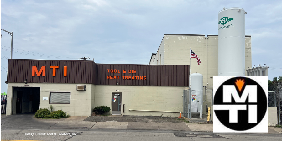
In the heart of Minnesota’s Twin Cities, a third-generation heat treating company continues to shape the backbone of manufacturing with precision and consistency. Established in 1948, Metal Treaters, Inc. began with a single Ipsen vacuum furnace used to treat door hinges for ovens and furnaces. From those early days, it has grown into a trusted partner for industries requiring meticulous control over metallurgical properties throughout the heat treating process.
The company expanded significantly in the 1970s when the second generation broadened its capabilities to include carburizing, induction hardening, and neutral hardening. That phase of growth laid the groundwork for today’s broader service offerings. Now under the guidance of its third generation, the focus is on integrating advanced technologies, enhancing efficiencies, and staying ahead of evolving compliance standards.
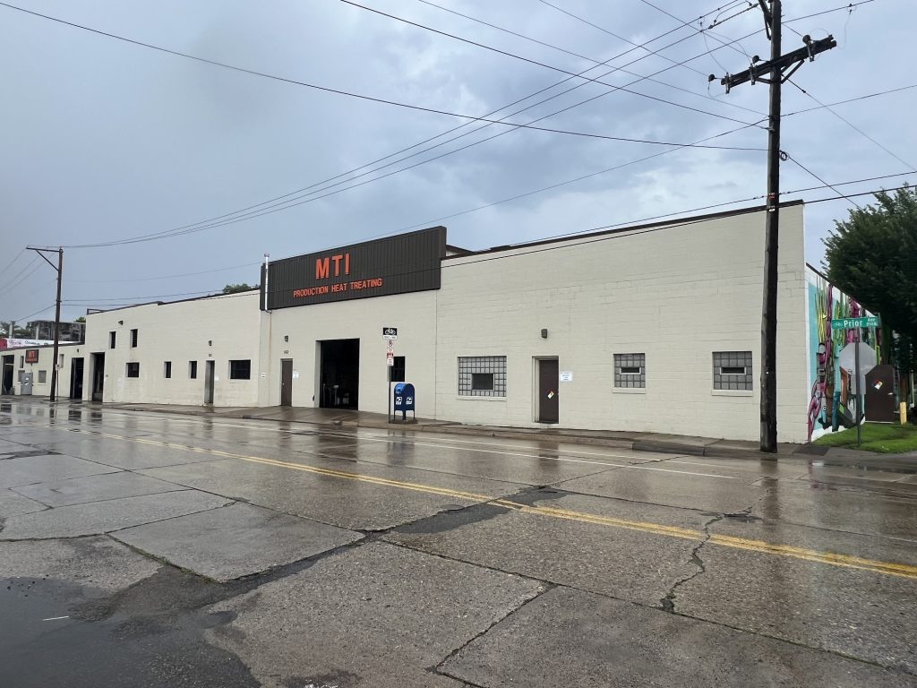
Metal Treaters, Inc. production, induction, shipping, and receiving side of facility | Image Credit: Metal Treaters, Inc.
Metal Treaters’ clients span the aerospace, defense, agricultural, construction, and medical sectors. A hallmark of the operation remains its vacuum heat treating expertise — a specialty dating back to its origin. Tool steels like A-2, D-2, and S-7, along with various stainless steels, are treated daily. Additional services include gas carburizing, carbonitriding, induction hardening and tempering, and cryogenic treatment.
What distinguishes this heat treater is its comprehensive internal control. Pyrometry is performed to AMS2750 standards, ensuring furnace accuracy and consistency. Metal Treaters also fabricates custom fixtures, racks, and induction coils, which allows them to tailor solutions, reduce job costs, and maintain quick turnaround times. These capabilities are especially valuable for manufacturers without in-house heat treating resources or those working with highly specialized components.
The facility operates eight furnaces, including four vacuum furnaces and four carburizing furnaces. They also utilize twenty-five tempering ovens, nine induction stations, seventeen hardness testers, and two deep freezers. All work is processed through batch ovens, which are optimized for flexibility and precision rather than oversized loads. With jobs that run in parallel and an established logistics network, including four daily route trucks serving the Twin Cities, the operation is built for both responsiveness and repeatability.
Growth has never depended on traditional advertising. Instead, the business has earned new work through word-of-mouth referrals and discussions at trade shows. This approach has attracted a wide range of challenging and high-profile jobs, from components used in space exploration and defense to tooling for medical and construction applications. Each project is approached with the same attention to detail, regardless of size or industry.
Looking ahead, the company aims to expand its use of automation in induction heat treating while continuing to meet the most rigorous technical standards. Plans also include maintaining a workplace culture that emphasizes collaboration, accountability, and long-term client relationships.
Through decades of change, Metal Treaters has remained grounded in technical excellence and responsive service. While tools, materials, and specifications have evolved, the guiding principles behind each treated part have stayed the same: precision, reliability, and craftsmanship.
For more information:
Metal Treaters, Inc.
859 Prior Avenue St. Paul, Minnesota 55104
joannea@metaltreaters.com metaltreaters.com
Main image: Metal Treaters, Inc. vacuum and office side of facility | Image Credit: Metal Treaters, Inc.
Hybar LLC has secured financing to support construction of a second electric rebar mini mill, a project that will expand domestic steelmaking capacity through electric arc furnace technology. The additional mill will increase reinforcing steel production for the U.S. construction sector.
The company announced it has secured approximately $1.1 billion in financing to support the expansion, which will be built adjacent to the company’s existing facility in Osceola, Arkansas. Upon completion, the second mill is expected to double the company’s annual reinforcing steel production capacity to approximately 1.3 million tons.
SMS group supplied the company’s electric arc furnace, continuous caster, and rolling mill for the existing facility. Now, SMS group has been commissioned to supply the technology and equipment for the expansion mill. Construction is expected to be completed in about 24 months.
Hybar’s rebar is being used in data center projects, medical campus expansions, the energy infrastructure buildout, and the continued repair and upgrading of roads, bridges, and tunnels. Hybar plans to continue penetrating these markets with the expansion mill.
Press release is available in its original form here.
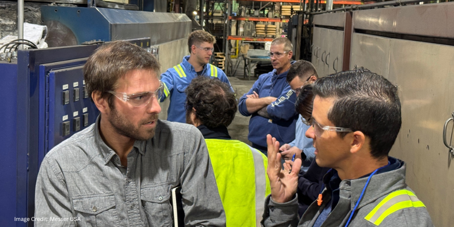
In this Technical Tuesday installment of Answers in the Atmosphere, David (Dave) Wolff, an independent expert focusing on industrial atmospheres for heat treat applications, examines how technical support has evolved from a value-added service into a key differentiator among industrial gas suppliers. Drawing on industry history and insights from Messer LLC, Wolff explores the range of support models available today and the factors heat treaters should consider when evaluating gas supply partnerships beyond price alone.
This informative piecewas first released in Heat Treat Today’sJuly 2026 Annual Super Brands Issue print edition.
Do you have the technical support you need? Not all industrial gas suppliers are the same when it comes to technical support and gas delivery offerings. A critical look must be taken to consider how much technical support you can be looking to your supplier for when signing a gas contract.
We’ll look at a bit of history of the differentiation of technical support offerings in the industrial gases space before homing in on how one specific has supplier, Messer LLC, offers their support so you can better evaluate the cost of gas supply alongside the level of technical support your operations may require.
A Bit of History
Industrial gases have long been treated as commodities, making differentiation among suppliers a persistent challenge. In the early years of the industry (through the 1950s), gas applications were narrowly utilized, especially for the primary steelmaking and refining industries, and most technical knowledge remained with these end user rather than the supplier.
To increase traction with their smaller manufacturing clients, industrial gas suppliers began pairing gas delivery with technical support to help these clients use gases safely and achieve productivity gains. This full-service model propelled increased industrial gas adoption across more general industries.
By the 1970s, the use of industrial gases had become more widespread to include industries like heat treating. Clients were increasing their knowledge of these gases and sought to improve labor and energy efficiency as well as reduce manufacturing costs.
This knowledge increase brought intensified competition for suppliers, prompting a shift toward offering range of service models. Some suppliers reduced or separated technical support to compete on price, while others continued to emphasize integrated service and application expertise. For example, in the 1980s Airgas reduced their technical support to provide a bare product approach at a lower price point. This action prompted other major gas suppliers to adjust their approach and offer technical support selectively, and at times for an additional cost.
Today, these technical support offerings are widely varied. The rest of the discussion is taken from an interview I was privileged to have with Grzegorz Moroz, program manager at Messer LLC.
Supporting Furnace Owners in a Changing Environment
Moroz first spoke about heat treaters’ long reliance on gases to maintain furnace atmospheres. Early-generation atmospheres, such as exothermic and endothermic gas, acetylene, and dissociated ammonia, were effective for their time. Over the past decades, industrial gas companies have advanced the safe use of nitrogen- and hydrogen-based atmospheres among others to deliver greater precision and tighter process control.
According to Moroz, furnace owners face multiple challenges:
Higher quality expectations with shorter lead times and reduced costs
Increasing safety and emissions regulations
Greater automation across operations
A less experienced and more transient workforce
Types of Support
Industrial gas companies, Moroz continues, vary widely in the level of support they may offer. Some focus on gas delivery or a specific expertise, while others offer comprehensive technical, safety, and application support as part of the overall supply relationship. For Messer, solutions are tailored from a team of technical and product experts that support heat treating from efficient, safe, and reliable operations as well as play review.
Access to Support
There are different commercial models industrial gas providers employ to enable their services, explains Moroz. While most will not provide ongoing assistance to facilities supplied by their competitors to avoid conflicts of interest, practices vary across the industry. Even so, contract structures often limit many suppliers from being flexible in delivering technical resources. Informal technical advice may be provided occasionally from gas suppliers that maintain in-house expertise.
Multi-supplier arrangements are common. This may be due to increased volume demands, supply security, strategies, or differing gas specifications, so Messer routinely navigates this reality. However, be aware that larger suppliers often prefer being the sole provider of all gas requirements at a site.
In part 2, we’ll talk more about what’s involved in an installation technical assessment and considering the right industry supplier expert.
About The Author:
David (Dave) Wolff Industrial Gas Professional Wolff Engineering
Dave Wolff has over 40 years of project engineering, industrial gas generation and application engineering, marketing, and sales experience. Dave holds a degree in engineering science from Dartmouth College. Currently, he consults in the areas of industrial gas and chemical new product development and commercial introduction, as well as market development and selling practices.
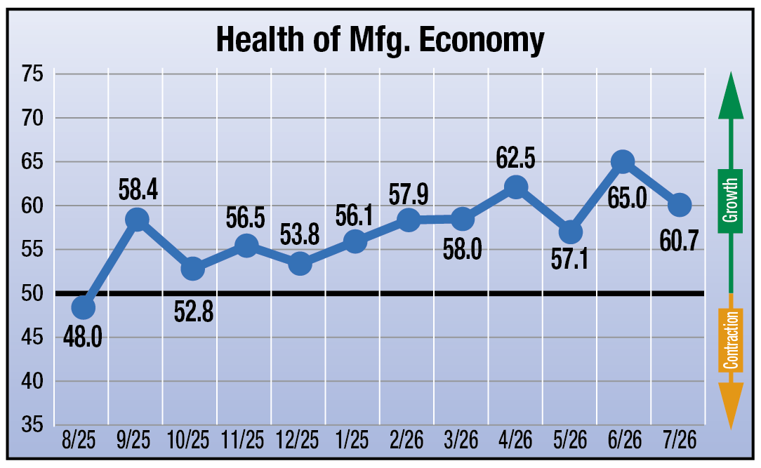
Heat Treat Today has gathered the four heat treat industry-specific economic indicators for July 2026. The results suggest continued growth across the heat treat industry, with suppliers anticipating healthy business conditions despite a modest cooling from June’s stronger outlook.
July’s data points to anticipated expansion in all four indicators, with each remaining above the growth threshold. Inquiries are projected at 64.3 (up from 54.0 in June), signaling renewed client activity. Bookings are expected to remain solid at 60.6 (up slightly from 60.0 in June). The Backlog index is forecast at 60.0 (from 61.0 in June). Meanwhile, the Health of the Manufacturing Economy index is projected at 60.7 (from 65.0 in June).
July’s indicators suggest suppliers continue to anticipate favorable business conditions heading into the heart of the summer production season. The sharp rebound in inquiries points to healthy client engagement, while bookings and backlog remain firmly in expansion territory, indicating sustained demand for heat treating services. Although manufacturers’ outlook for the broader economy moderated from June’s exceptionally strong reading, it continues to signal expected growth, reinforcing expectations that the industry will remain on stable footing in the month ahead.
The results from this month’s survey (July) are as follows: numbers above 50 indicate growth, numbers below 50 indicate contraction, and the number 50 indicates no change:
Anticipated change in Number of Inquiries from June to July: 64.3
Anticipated change in Value of Bookings from June to July: 60.6
Anticipated change in Size of Backlog from June to July: 60.0
Anticipated change in Health of the Manufacturing Economy from June to July: 60.7
Data for July 2026
The four index numbers are reported monthly by Heat Treat Today and made available on the website.
Heat TreatToday’sEconomic Indicatorsmeasure and report on four heat treat industry indices. Each month, approximately 800 individuals who classify themselves as suppliers to the North American heat treat industry receive the survey. Above are the results. Data collection began in June 2023. If you would like to participate in the monthly survey, please click here to subscribe.
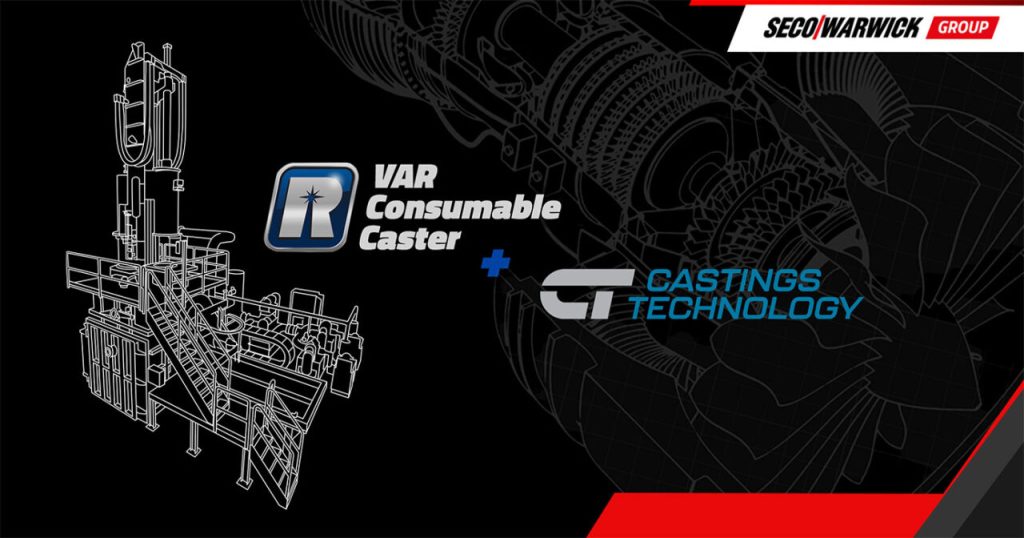
A titanium casting manufacturer is expanding its vacuum melting capacity with the installation of a vacuum arc remelting consumable casting furnace, increasing capacity for near-net-shape titanium components serving the aerospace industry. The investment is intended to improve production lead times while supporting growing demand for titanium castings used in high-performance applications.
Castings Technology chooses Retech VAR. | Image Credit: SECO/WARWICK Group
Castings Technology, the United Kingdom’s only commercial titanium casting specialist, selected a VAR Consumable Caster (VAR-CC) furnace from Retech, a global vacuum metallurgy company within the SECO/WARWICK Group based in North America. The furnace will be installed at the company’s new 18,000-square-meter facility, where it will be used to cast titanium ingots into ceramic molds.
Richard Cook Managing Director Castings Technology
“The delivery of the new VAR furnace will help us fulfill the growing needs of our exacting client base,” said Richard Cook, managing director of Castings Technology. “Due to dynamic growth and significant constraints within our current facility, we are in the process of relocating to a new site of about 18,000 square meter just a short distance away. The relocation is on plan, with a period of parallel operation continuing throughout 2026 to fully mitigate any risk to our clients’ programs.”
The new furnace is expected to support increased demand for titanium, especially from the aerospace sector, where backlogs have now surpassed pre-pandemic levels. Titanium’s high strength-to-weight ratio and corrosion resistance have made it a widely used material across many sectors, including aerospace, motorsport, medical prosthetics, restorative dentistry, and high-duty rotating equipment. Near-net-shape titanium casting also provides mechanical properties comparable to forged or wrought material while increasing fatigue resistance.
Press release is available in its original form here.


 Dr. Liang He, Senior Principal Application Engineer
 Steve Perret, Advanced Materials Processing Engineer