In this installment of Answers in the Atmosphere, David (Dave) Wolff, an independent expert focusing on industrial atmospheres for heat treat applications, examines what furnace owners should expect when their gas supplier conducts a technical assessment. Drawing on insights from Messer LLC, Wolff walks through the step-by-step process suppliers use to diagnose furnace atmosphere issues, from verifying process parameters to running detailed diagnostic surveys, and outlines the standards of technical competence, communication, and accountability that furnace owners should hold their industrial gas partners to.
This informative piecewas first released in Heat Treat Today’sAugust 2026 Annual Automotive Heat Treating print edition.
This column picks up the conversation leveraging the technological know-how of your gas supplier. If you missed it, read Part 1 in the Heat Treat Super Brands (July 2026) print edition. What follows are the insights and best practices that Messer LLC shared with me on what you need to prepare for a technical assessment with your supplier.
Technical Assessment
First, since business models vary throughout the industry, be sure you understand whether or not technical support will entail a specific fee. When establishing your gas supply contract, furnace owners should seek out suppliers who provide a flexible approach that will be aligned with their needs.
A supplier will often follow these steps when providing technical support to identify, prevent, or correct issues in your heat treat furnace:
Define and verify the problem to determine whether it originates from heat treatment, material handling, or operator error.
Verify incoming material to ensure the issue is not caused by raw material condition or pre-processing steps.
Check heat treatment process control parameters.
Verify furnace atmosphere integrity, inspecting gas supply lines, furnace connections, piping leaks, deliveries, and any repairs.
Evaluate furnace component, identify any changes in furnace structure or maintenance activities.
Review process parameters to confirm whether temperature, time, gas composition, or gas purity have changed.
Inspect exhaust systems, doors, and airflow, as disturbances can impact furnace performance.
After reviewing initial process data, a furnace atmosphere survey or targeted spot check may be conducted. This step may include:
Establishing furnace baseline conditions
Running furnace temperature profile tests
Measuring oxygen, CO, CO2, hydrogen content, and dew point
Conducting detailed modeling based on gas flows, heat transfer, or mass balances
Your provider may use advanced tools, such as Computational Fluid Dynamics (CFD) modeling, to analyze and resolve complex furnace atmosphere issues.
What to Expect: Evaluating Supplier Capabilities
Not all technical support delivers the same value. While many suppliers have strong technical capabilities, access can vary based on internal structures or business models. Some suppliers provide expanded support.
Furnace owners should expect their industrial gas partner to:
Demonstrate strong technical competence and ability to identify root causes
Communicate clearly in practical terms familiar to operations teams
Deliver recommendations with a complete implementation plan including safety, training, costs, timelines, risks, and benefits
Clearly define responsibilities between the furnace owner and gas provider
Final Thoughts
For furnace owners, the industrial gas supply space can seem like a lot of the same offerings, but a closer look at how technical support varies from one supplier to the next can significantly fine tune your operation’s ability to adapt and respond to your furnace needs. The key is to be honest about what your own operations can accomplish on its own before reviewing industrial gas contracts (more on contracts in the June 2026 “Answers in the Atmosphere” installment) and committing to a too low or too flexible plan for technical support.
About The Author:
David (Dave) Wolff Industrial Gas Professional Wolff Engineering
Dave Wolff has over 40 years of project engineering, industrial gas generation and application engineering, marketing, and sales experience. Dave holds a degree in engineering science from Dartmouth College. Currently, he consults in the areas of industrial gas and chemical new product development and commercial introduction, as well as market development and selling practices.
A small amount of hidden water at the bottom of a quench tank can rapidly escalate into a violent fire hazard. In this Technical Tuesday installment, Bruno Scomazzon, general manager of Precision Heat Treat Ltd., discusses how free water develops, why conventional testing can miss it, and the practical steps heat treaters can take to detect and eliminate the risk.
This informative piece was first released inHeat Treat Today’sJuly 2026 Annual Super Brands Issue print edition.
Most heat treat shops never see the danger building beneath the surface of their quench oil. Drop by drop, water stratifies, tipping the balance and awakening the dragon.
In an integral quench furnace, quenching is a controlled process. When a hot load is submerged, vapor is generated below the surface, rising and mixing with the furnace atmosphere. Oil temperature, atmosphere, and vapor generation are managed so that any combustion remains contained, with gases and vapor generated and relieved in a controlled manner. Under normal conditions, the process is stable and predictable.
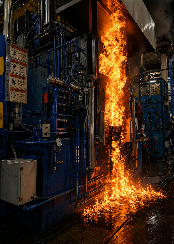
AI-generated illustration based on a potential quench fire scenario. No actual integral quench furnaces were harmed in the making of this article. | Image Credit: Precision Heat Treat Ltd.
Add water, and you introduce a completely different hazard. It can turn violent before you understand or can react to what you are seeing. In this scenario, when the hot load is submerged, water at the bottom of the tank flashes instantly to steam, expanding roughly 1,600 times in volume. That expansion happens almost instantly, and the resulting increase in volume overwhelms the system.
As the steam rises, each bubble becomes coated with oil. Rapid expansion displaces oil and generates a large volume of vapor in a very short period of time. In a confined quench chamber, that surge carries oil and vapor together toward the burn-off vent and the doors.
There are typically two doors in the system, and they behave very differently. The inner door separates the hot zone from the quench tank. During quenching, the hot zone is typically operating around 1550°F. If oil is forced into the hot zone, it will vaporize and burn, generating products of combustion that can lead to a more severe internal event. However, this is not where the external fire develops. The outer door separates the quench chamber from the outside. During a surge, oil and vapor push upon this door and can be forced out. When the flammable oil vapor and furnace atmosphere reach an ignition source such as the flame curtain pilot, it will ignite violently.
At that point, the fire is no longer confined or controlled. Oil that reaches the exterior can spread along the floor and around the base of the furnace. Once outside the chamber, any oil present becomes fuel, and the fire can spread quickly.
How Water and Oil Interact
Two different conditions exist: dissolved water and free water. Dissolved water is moisture within the oil, typically when the oil is hot. It is part of normal operation and must be monitored. Elevated dissolved water levels are mainly a performance and control problem, not the immediate hazard. But if it continues to rise, it leads to free water, which is the hazard. Free water is water that has separated from the oil and settled to the bottom of the tank.
As a general guideline for dissolved water:
Below 100 ppm (0.01%): very good
100–200 ppm (0.01–0.02%): acceptable
200–500 ppm (0.02–0.05%): caution range
Above 500 ppm (0.05%): corrective action required
These values apply to dissolved water in the oil — not the free water condition at the bottom of the tank, which is the condition of greatest concern. As the oil cools, its ability to hold moisture decreases. Excess water comes out of solution, forms small droplets, and over time settles to the bottom. This creates stratification — the formation of distinct layers. Oil floats above, leaving a layer of free water at the bottom. That bottom layer is the dangerous condition, the same condition that drives the surge event described earlier.
Water Does Not Just Appear — It Gets Introduced
Common water sources include condensation during shutdowns and startups, along with operator or maintenance oversights that allow water or contaminated oil to enter the system. On older units, water-cooled components can develop leaks over time, allowing water to enter the oil slowly and go unnoticed. Leaking roof components or failed hood caps can also allow water to reach the furnace and make its way into the tank.
Water does not always find its way into a quench tank through a leaking cooler, heat exchanger, or outside source. During extended shutdowns, particularly during cooler months or periods of high humidity, moisture can condense on the ceiling and sidewalls of the quench vestibule and tank area. As the furnace heats up and the colder oil tank lags behind, water droplets can form and eventually fall into the oil. | Image Credit: Precision Heat Treat Ltd.
Because this develops gradually and often out of sight, everyone in the shop needs to stay alert. If something does not look right, or behave abnormally, report it immediately.
Detecting Water: What the Operator Sees First
Detecting free water in a quench tank is not as straightforward as it sounds. In many cases, the first indication is not a test result but a change in furnace behavior.
Changes in burn-off flame height, flame recovery time, unusual oil discharge (“burping”), or abnormal sounds during quenching are often early warning signs that something in the system has changed. All furnace operators should be trained to recognize these changes and treat them as indicators that the condition of the quench may no longer be normal.
Confirming with Sampling and Testing
Most monitoring systems measure dissolved water in circulating oil — not free water at the bottom. That distinction matters. Water that is mixed in the oil can be measured and trended. Water that has separated and settled to the bottom may not be detected by standard sampling methods. A sample taken from a circulating line or mid-depth in the tank can show acceptable results while free water remains undetected. These values are typically determined through lab analysis or in-shop test kits that measure dissolved water in quench oil. Standard tank sampling does not distinguish between dissolved and free water. That is why where you take the sample matters as much as how you test it.
Bottom sampling is critical. Pulling oil from the lowest point in the tank after the furnace has been idle, such as over a weekend, is often the best way to identify free water. If you do not already have a way to sample from the bottom of your tank, you should plan to install a dedicated drain or sample port. A bottom sample should be part of your weekly oil monitoring.
In the absence of a dedicated bottom drain, a simple method can still be used. Tubing can be inserted down through the fill or access point until it reaches the bottom. By sealing the top of the tube, the oil column inside is held in place as it is withdrawn, allowing a sample from the lowest point in the tank. The sample must be taken before any agitation or circulation begins. If the oil has been disturbed, the water can be temporarily mixed and the true condition at the bottom may not be seen.
The sample is placed in a clear glass beaker and allowed to stand. If water is present in any significant amount, it will usually be obvious, especially when compared to a sample taken from mid-depth or circulating oil. If it is not obvious, a crackle test can be used as a quick field check. A small sample of oil is placed on a hot surface, typically around 300–350°F. If free water is present, it flashes to steam and produces visible bubbling or crackling.
In practice, the severity of the reaction gives a clear visual indication of the condition:
No reaction: acceptable, continue to run
Light fizz or fine bubbles: trace water present, monitor
Moderate crackle or popping: plan corrective action
Strong crackle or aggressive bubbling: correct the condition before continuing
A consistent reaction across samples is the key indicator. This is not a precise measurement, but it is a reliable field guide. If it is reacting hard, you are already past where you want to be.
Sending samples for quarterly lab analysis provides a more complete picture of oil condition, including water content, oxidation, viscosity, contamination, and quench performance. This helps track dissolved water levels and overall oil health. In-shop test kits and commercial monitoring systems are also available, but none replace the need to understand what is happening at the bottom of the tank.
Removing Free Water from the Quench Tank
When free water is present at the bottom of the tank, it must be removed. This is an immediate hazard. In practice, removing oil from the top-down is often the most controlled approach. Oil is siphoned from the surface, working downward and stopping about a foot above the bottom to avoid disturbing the settled water layer.
This allows clean oil to be removed first while leaving the water undisturbed. Attempting to remove water directly through a bottom drain is not always effective, particularly in larger tanks, as it can pull both water and usable oil and disturb the interface between the two.
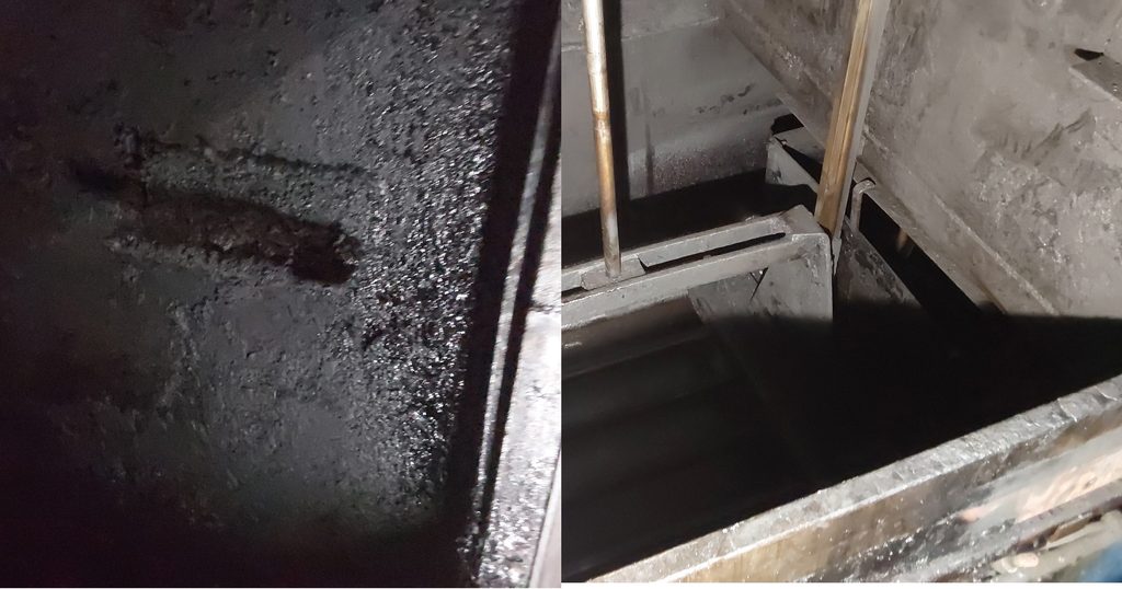
Left: Accumulated oil sludge, soot, and scale deposits inside a quench tank. Right: The same area after cleaning. These deposits can build up over time and provide fuel for a fire. Regular tank cleaning is an often-overlooked part of quench oil stewardship and fire prevention. | Image Credit: Precision Heat Treat Ltd.
The removed oil can be placed into totes and allowed to sit undisturbed for several days so any remaining water can separate and settle. Clean oil can then be recovered from the top. The remaining oil and water mixture in both the tank and tote should be recycled. Other methods, such as vacuum dehydration or oil reclamation systems, can be used where available and are often more effective at removing both free and dissolved water, but are not always practical in every shop.
With the oil removed, this is an ideal time to carry out thorough tank cleaning. Over time, quench oils form sludge, a combination of oxidation byproducts, degraded oil, carbon, scale, and fines from processed parts. This material settles to the bottom, can trap and hold water, and hide it from normal sampling. As it builds up, it interferes with oil flow and agitation, affecting quench performance.
Tanks require periodic cleaning, typically every 12 to 18 months, depending on usage and condition. This is the time to remove sludge and clean deposits from the walls and ceiling.
It is also an opportunity to inspect agitation systems, elevators, rollers, and other components, and carry out preventative maintenance. Proper lockout procedures and confined space protocols must be followed.
The Bottom Line
Free water is an immediate hazard. If allowed to accumulate, it can trigger a rapid pressure event and an uncontrolled fire. Once it starts, it escalates quickly and is difficult to contain, putting personnel and the entire operation at risk.
Regular bottom sampling for free water must be part of your quality control.
Acknowledgements
The author would like to thank Daniel H. Herring, “The Heat Treat Doctor®” at The HERRING GROUP, Inc.
About The Author:
Bruno Scomazzon General Manager Precision Heat Treat Ltd.
Bruno Scomazzon is the general manager of Precision Heat Treat Ltd. in Surrey, British Columbia, Canada, with over 40 years of experience in metallurgical processes and heat treating operations.
Cleveland-Cliffs is investing $1 billion to modernize its Middletown Works steelmaking facility in Ohio, including upgrades and a planned rebuild of the site’s blast furnace as part of a broader project focused on production efficiency and emissions reduction.
The investment will be funded equally by Cleveland-Cliffs and a $500 million grant from the U.S. Department of Energy (DOE). The project is expected to extend the operating life of Middletown Works while maintaining its existing steelmaking capacity.
The modernization will include upgrades to the blast furnace, advanced material-handling infrastructure, and AI-enabled process controls. Cleveland-Cliffs also plans to construct a cogeneration facility that will capture blast furnace gas and use it to generate electricity and steam for the plant.
The company expects the cogeneration system to reduce Middletown Works’ reliance on purchased electricity and natural gas while lowering greenhouse gas emissions associated with the facility’s operations.
The project is expected to begin in 2026, with the blast furnace rebuild scheduled for completion in the first quarter of 2030. Cleveland-Cliffs anticipates that construction will support approximately 2,500 jobs while maintaining about 2,500 existing positions at Middletown Works.
Located in Middletown, Ohio, the integrated steelmaking facility produces approximately 3 million tons of raw steel annually. Its products primarily serve the automotive market, including applications requiring advanced high-strength steels.
Press release is available in its original form here.
Welcome toHeat Treat Today’sThis Week in Heat TreatSocial Media. From battle-tested swords and glowing tool steel to microscopic works of art — and even a little lingering World Cup fever — heat treat social media had a little bit of everything! We scrolled, watched, learned, tested our metallurgy knowledge, and had some fun with posts that showcase the science, skill, and creativity behind this industry.
As you know, there is so much content available on the web that it’s next to impossible to sift through all of the articles and posts that flood our inboxes and notifications on a daily basis. So, Heat Treat Today is here to bring you the latest in compelling, inspiring, and entertaining heat treat news from the different social media venues that you’ve just got to see and read!If you have content that everyone has to see, please send the link to editor@heattreattoday.com.
1. May the Best Sword Win
Ready for some binge-worthy metallurgy? All six episodes of Cast in Steel Season One are now streaming, following university teams as they design, cast, and battle-test George Washington-inspired swords using modern metalcasting and engineering. Start with Episode 1 below, then head over to YouTube to watch the rest of the series.
2. VIM Steps Into the Spotlight
It may usually happen behind the scenes, but vacuum induction melting gets center stage in this SECO/TALKS episode. Take a closer look at how VIM supports the clean, consistent materials required for demanding aerospace applications.
3. What’s Cooking at 1725°F?
Dinner may take eight hours, but we wouldn’t recommend taking a bite. Blackout Industries gives viewers a glowing look at S7 tool steel heated to 1725°F.
It’s alphabet soup for the metallurgist’s soul! Metallurgical Engineering challenges followers to identify which common metallic crystal structure is the most ductile. What’s your guess?
Who needs a paintbrush when you have maraging steel and Beraha’s reagent? Buehler’s August microstructure calendar winner puts the art puts the art in metallography with this colorful look at additively manufactured MS1 steel.
6. World Cup Fever: Still Going Strong
The World Cup may be over, but our soccer fever isn’t! We’re throwing it back to a Bodycote #MetalMonday that puts aluminum in the starting lineup and explores why the metal is well suited for modern goal frames.
7. HTT Can Take the Heat
Neither distance nor a little heat can keep Heat TreatToday from making the rounds. Our latest sighting takes us all the way to western Washington, where wildfire smoke made for a hazy backdrop — and a reminder of the first responders working to protect communities across the state.
8. When Steel Gets the Cold Shoulder
Turns out, dropping the temperature can dramatically change how some steels behave. GaugeHow breaks down ductile versus brittle fracture — and shows why crystal structure, temperature, load speed, and even the shape of a part can help determine whether metal bends or breaks.
There’s plenty to talk about in this latest episode of Heat TreatRadio when two competing heat treat software platforms come under the same ownership. Doug Glenn joins Steelhead Technologies CEO Jeff Halonen to dig into the Visual Shop and Bluestreak acquisitions and what’s ahead.
10. America’s Next Top Microstructure
Metallurgists, it’s time for your microstructures to work the runway. An online metallography competition is inviting materials pros to turn microscopic science into frame-worthy art.
Whether it’s putting microstructures in the spotlight, exploring why steel bends or breaks, or taking metallurgy onto the soccer pitch, there’s always something fascinating heating up on social media. Have a great weekend!
Ninety years is a remarkable milestone for any company. In the heat treating industry, where technologies, markets, and client expectations have continually evolved, reaching that anniversary requires more than longevity — it requires adaptability.
For W.H. Kay Company, that adaptability has been the defining characteristic since William Henry Kay founded the company in 1936, during the final years of the Great Depression. What began as a Cleveland-based manufacturer’s representative for Eclipse Combustion Equipment has grown into a company recognized throughout North America for combustion systems, used heat treating equipment, and practical process solutions.
Along the way, W.H. Kay has come to describe itself as “The Elder Statesman of Used Ovens and Treating Furnaces” — a moniker that reflects both the longevity of the business and the used-equipment specialty it developed over decades.
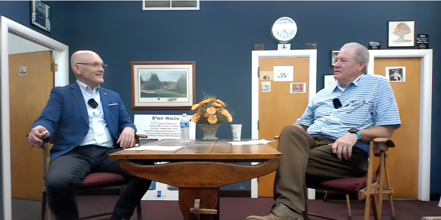
Doug Glenn, publisher of Heat TreatToday (left), sat down with Michael Kay, president of W.H. Kay (right), about the company’s 90-year journey — from its beginnings as a combustion equipment representative to becoming a trusted resource for industrial thermal processing solutions. | Image Credit: Heat TreatToday
Today, under the leadership of third-generation owner Michael Kay, the company continues to serve commercial heat treaters and manufacturers while maintaining a relationship with Eclipse — now part of Honeywell — that has lasted since the day the company opened its doors.
“It’s amazing,” Kay said. “We’ve represented Eclipse since 1936.”
From Representation to Reinvention
W.H. Kay’s history reflects many of the changes that have shaped industrial thermal processing over the past nine decades.
William Henry Kay, Michael Kay’s grandfather, represented Eclipse Burners and Furnaces throughout northern Ohio. When Eclipse phased out of furnace manufacturing, Michael Kay’s father, Frank, and uncle, Bill, continued serving longtime clients who wanted additional furnaces like the Eclipse equipment they already operated. Using existing furnace prints, W.H. Kay had units fabricated to meet those clients’ needs.
That work eventually opened another avenue for the company as clients purchasing new equipment began asking what to do with their existing furnaces. W.H. Kay started accepting equipment on trade and finding new buyers for it, gradually establishing the used-equipment business that remains a significant part of the company today.
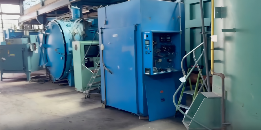
A variety of equipment at the W.H. Kay facility | Image Credit: Heat TreatToday
Today, the company’s Solon, Ohio, warehouse houses hundreds of pieces of equipment ranging from tempering ovens and pit furnaces to vacuum furnaces, integral quench systems, atmosphere generators, and ancillary processing equipment.
The Value of Staying Close to the Client
Although W.H. Kay still supplies combustion products and represents JPW Industrial Ovens & Furnaces, Kay believes the company’s success has never been about simply selling products. “If you’re just taking orders, you’re kind of in trouble,” he said. “You’ve got to be proactive.”
That approach extends to how the company works with clients, beginning with an understanding of the application rather than simply supplying the equipment initially requested. A client inquiring about a 1600°F furnace, for example, may actually be operating at only 900°F — a distinction that can point to an entirely different equipment solution. “You’ve got to listen,” he said. “What they’re asking for might not be what they actually need.”
The willingness to listen can remain valuable long after the initial sale. Kay recalled a recent call from a client who had purchased a furnace seven years earlier, and, no longer needing it, approached the company about buying it back. Other clients contact the company when they need something larger or have equipment they no longer use. For W.H. Kay, responding to those changing needs has made used equipment more than an inventory business; it has become another way to provide clients with options.
Providing a used-equipment option does not, in Kay’s experience, come at the expense of new furnace sales. Over his four decades in the industry, he said, clients who intend to purchase new equipment generally do so, while those considering used equipment often have a different set of requirements. “In the course of 40 years, I’ve never seen a used [furnace] take over a new account,” he said. “If people are buying new, they’re buying new. If they’re buying used, they’re buying used.” Instead, he sees used equipment as another way to help clients solve a problem.
If a manufacturer needs an oven immediately rather than waiting several months for a new build, used equipment can provide an option that better fits the client’s timeline. “We could quote him a new one in 16 weeks,” Kay said. “Or we could have one in four days.” With hundreds of pieces of equipment in its Solon warehouse, the company can sometimes match a client’s requirements with a unit already in inventory, providing an alternative when lead time is as important as the equipment itself.
Understanding those circumstances requires more than waiting for an inquiry. It also means getting out of the office and spending time with clients. “You’ve got to get in the flow,” he said.
Whether checking on a furnace sold years earlier or simply stopping in to ask how things are going, those visits help the company stay aware of how clients’ operations and equipment needs are changing. A conversation might reveal a furnace the client no longer uses, a need for something larger, or anther equipment requirement that W.H. Kay can help address.
“My father used to say you can waste a lot of time coming into the office every day,” Kay recalled. “You need to be out with [clients].”
The practice has endured even as industrial sales have changed around it. Kay remembers beginning his career in 1985 carrying a substantial Eclipse product catalog on sales calls, followed by the arrival of fax machines that dramatically shortened the time required to submit and acknowledge orders. Email and the internet have transformed the process again, while the number of salespeople regularly making in-person calls has declined. “In some cases,” he said, “people tell me they haven’t seen a salesperson in six months.”
For W.H. Kay, continuing to make those visits is less about maintaining an old-fashioned sales practice than staying close to the client. The tools of industrial sales may have changed considerably over 90 years, but the company still sees listening, understanding the operation, and building rapport as essential to finding the right solution.
Listening before selling, understanding the application, and building long-term relationships have remained central to the company as the business has weathered changing technologies, shifting markets, and multiple generations of industrial manufacturing.
Creating Your Own Good Luck
W.H. Kay’s nine decades have included more than changes in how equipment is bought and sold. The applications themselves continue to evolve.
Kay has seen growing activity around aluminum heat treatment, including aging and drop-bottom furnace applications, as manufacturers pursue lighter materials. The company has also supplied ovens for composite curing and other lower-temperature processes. Additive manufacturing presents another evolving area; even when parts are produced through 3D printing, Kay noted, thermal processes such as stress relieving can remain necessary.
Through those changes, Kay expects industrial heating and thermal processing to continue finding applications in emerging manufacturing technologies. The greater lesson he draws from more than four decades in the business, however, is less about predicting which technology or market will come next than about remaining engaged enough to respond when it does.
Kay returned to one idea again and again: success isn’t about waiting for opportunities to arrive — it’s about putting yourself where they can happen. Whether checking in on clients, making sales calls, or simply staying engaged with the industry, he believes consistent effort creates its own momentum. The advice he offers today is the same philosophy that has guided his career for more than four decades.
“Create your own good luck,” Kay said. “Keep at it. Get out of the office.”
Ninety years after William Henry Kay founded the company, the equipment, technologies, and methods of doing business have changed considerably, but the philosophy remains much the same: listen to clients, stay engaged, and keep showing up. It continues to guide his company — one client visit, one solution, and one furnace at a time.
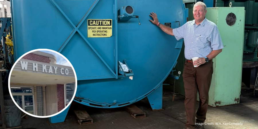
Main image shows Michael Kay posing with a vacuum furnace with a photo inset of the entrance to the W.H. Kay facility. | Image credit: W.H. Kay Company If you have any comments or queries on this article, let us know at editor@heattreattoday.com.
Jim Roberts of U.S. Ignition engages readers in a Combustion Corner column about the basics of heat transfer — breaking down the First Law of Thermodynamics into practical terms for heat treaters, then using a real-world example to show how ambient load temperature can meaningfully shift BTU energy requirements and furnace performance.
This column was first released in Heat Treat Today’sJuly 2026 Annual Super Brands Issue print edition.
A furnace guy walks into a heat treat plant and says to the group of operators, “I just transferred here.” One of the furnace operators says, “Perfect, it’s what we do best.” Huh…? Well, of course they transfer heat. That’s what heat treaters do better than anyone else — we transfer heat. And the science of this transfer is called thermodynamics.
In the world of physics, there are four laws of thermodynamics, which are centered on the movement and flow of heat between objects. We’ll start with the concept of heat transfer, based on the First Law of Thermodynamics.
The concept of thermal conservation states that energy cannot be created or destroyed; it can only be transferred or transformed. In other words, whatever we put into the furnace in the form of heat will be the same amount that comes out or is absorbed. Additionally, the part we want to heat treat has thermal mass and therefore has heat as well. We say that the load is “cold,” but really, it’s normally coming into the process at room temperature, which means there is energy there that gives us a head start in heating it up.
Then, we know that the heat we feel from the shell of the furnace was not absorbed by the load but is part of the energy that we put into the furnace, it just wasn’t absorbed by the load. So, the heat exits the furnace into the room to be absorbed by other items that are not in equilibrium. The energy is always there, continuing on. It’s a wild concept, isn’t it?
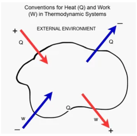
Figure 1. The First Law of Thermodynamics | Image Credit: Jim Roberts
As shown in Figure 1, heat enters the furnace (designation “Q”). Heat then enters the work, which is designation “W” (e.g., load, furnace). Work absorbs most of the heat, but it also releases energy since it is starting to go towards a state of equilibrium, meaning heat in and heat released are equal. Then, the work releases energy into the area where it is not as hot and tries to heat it up and gain equilibrium. That’s the furnace guy standing there, the room, the building, etc. All of these things become the next stage of “work.”
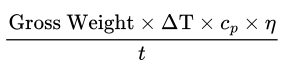
So, when we get to the point of calculating the input (energy usage), we generally use BTU or KW ratings. We also must consider ambient temperature of the work because that Delta T, or temperature variance, is what we are having to account for. If that load is sitting at 70°F, it has value as a heat source, so we need to account for that. You will recall that the formula that is commonly used for calculating heat load is:
This will give you BTU requirements after you then apply an efficiency. Sometimes that’s an estimated efficiency. Let’s show the difference in that energy requirement that needs to be provided when the latent heat in the load is different.
Let’s suppose we are a heat treater in central Michigan. It’s December. We have been accustomed to staging our bulk parts for heat treating out on our open loading dock. The furnace is suddenly not performing like it did earlier in the year. It’s the same 1,000 lb load. Earlier in the year, our formula accounted for the 70°F load temperature coming in. Our equation would be:
In this example, if we bring the work in from the frozen loading dock at 20°F, the heat required jumps to 401,231 BTU energy required per hour. It’s not a lot, but the furnace will notice and not perform as well since the burners tend to run at a fixed setting.
Even slight variations can make a big difference in cost and performance. Simple and yet slightly confusing science is behind it all.
About The Author:
Jim Roberts President US Ignition
Jim Roberts president at U.S. Ignition, began his 45-year career in the burner and heat recovery industry focused on heat treating specifically in 1979. He worked for and helped start up WB Combustion in Hales Corners, Wisconsin. In 1985 he joined Eclipse Engineering in Rockford, IL, specializing in heat treating-related combustion equipment/burners. Inducted into the American Gas Association’s Hall of Flame for service in training gas company field managers, Jim is a former president of MTI and has contributed to countless seminars on fuel reduction and combustion-related practices.
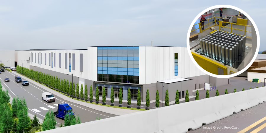
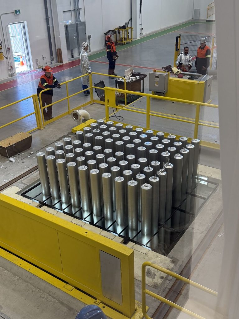
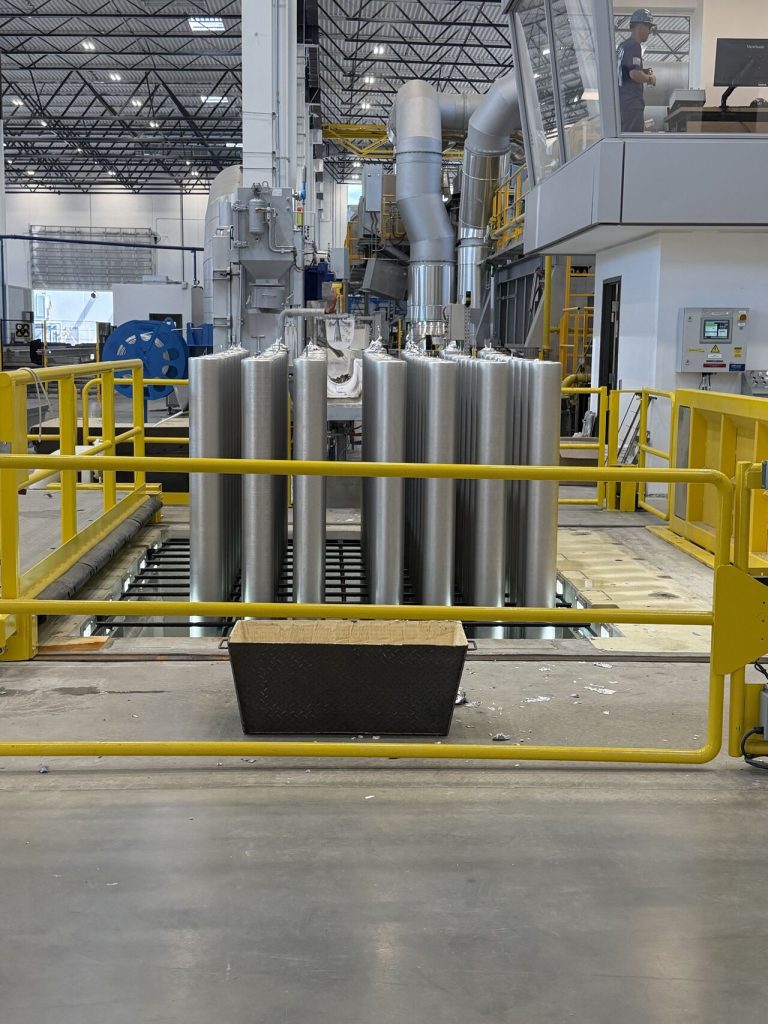
RevoCast Aluminum Billets Ltd., a manufacturer of recycled aluminum billets, has begun production at a new aluminum remelting facility in British Columbia, adding more than 80,000 tons of annual billet capacity to serve the North American extrusion market.
The company has successfully cast its first aluminum billet at its new remelting facility in Langley, British Columbia, marking the start of operations at the Canadian plant.
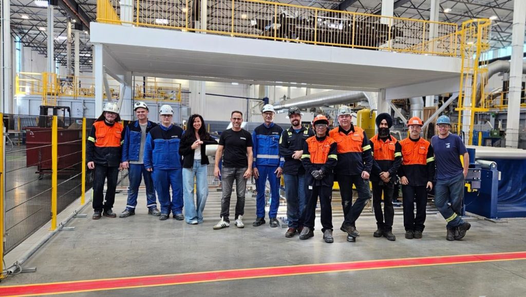
The first billet was cast on August 1, 2026, following the completion of the new facility. RevoCast said the milestone resulted from planning and collaboration among its employees, partners, and suppliers, including Wagstaff, Inc., a manufacturer of aluminum direct-chill casting equipment, and HERTWICH Engineering GmbH, a supplier of aluminum casthouse equipment and technology.
The aluminum remelting facility has an annual production capacity of more than 80,000 tons (176.4 million pounds) of aluminum billets and is designed to serve extrusion markets on the West Coast and in the Pacific Northwest.
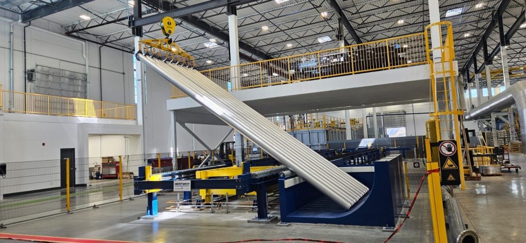
RevoCast produces remelt billets in the 6xxx aluminum alloy series. The billets are available in diameters of 178 mm (7 in) and 203 mm (8 in), with maximum sellable lengths of 7.3 m (288 in). The facility incorporates energy-efficient equipment and is designed to use high levels of recycled content while reducing carbon emissions associated with billet production.
The company aims to deliver high-quality aluminum billets while strengthening the North American aluminum supply chain.
Press release is available in its original form here. Additional information provided by RevoCast on their website.
Un tratamiento térmico por inducción fiable depende de algo más que la metalurgia: requiere un desempeño preciso y repetible de cada parte del sistema de inducción. En este artículo, Heat TreatTodayAaron Goodwin, ingeniero de desarrollo de negocios de Inductoheat, explora cómo las bobinas de inducción, las fuentes de alimentación, los sistemas de temple y el monitoreo del proceso en tiempo real trabajan en conjunto para lograr de manera consistente la dureza, la profundidad de capa y la microestructura que demandan los componentes automotrices actuales. Conozca cómo la confiabilidad del equipo, el mantenimiento preventivo y el control del proceso ayudan a los fabricantes a reducir la variabilidad, mejorar la calidad y mantener la producción funcionando eficientemente.
Este artículo informativo se publicó por primera vez enHeat Treat Today’sAugust 2026 Annual Automotive Heat Treating print edition.
Existe una relación fundamental entre el diseño de un componente automotriz y los requisitos de su tratamiento térmico. En la fabricación moderna de vehículos ya sean camiones, SUVs o crossovers, el margen de error es extremadamente reducido. Componentes como ejes, engranes, flechas de transmisión y otros elementos del motor y del tren motriz, están sometidos a elevadas cargas, altos niveles de torque y condiciones de operación cada vez más exigentes. Estos vehículos deben ofrecer un equilibrio entre durabilidad, eficiencia, operación silenciosa y desempeño. Además, deben responder de manera confiable a una amplia variedad de escenarios de conducción, desde el tráfico urbano con constantes arranques y paradas, hasta el remolque de cargas, la conducción todoterreno y los recorridos de larga distancia.
Independientemente del tipo de vehículo, existe una constante. Si bien la selección del material y el diseño de ingeniería son fundamentales, la consistencia y confiabilidad del tratamiento térmico son las que determinan si un componente cumplirá con el desempeño esperado en condiciones reales de servicio. El calentamiento por inducción para el endurecimiento superficial de componentes automotrices es una de las tecnologías preferidas por los ingenieros de diseño, y contar con equipos fiables de calentamiento por inducción es fundamental.
Desde la bobina de inducción hasta la fuente de potencia y el sistema de temple, cada elemento debe operar con precisión y repetibilidad en cada ciclo de producción. El endurecimiento superficial por inducción depende de un conjunto de variables estrictamente controladas que deben trabajar de manera sincronizada. Cuando el proceso permanece estable, se obtienen componentes tratados térmicamente de calidad; cuando esto no ocurre, surge la variabilidad y, con ella el riesgo.
La Relación entre el Equipo de Inducción y la Metalurgia
Los componentes tratados térmicamente se evalúan principalmente por tres características: la dureza, la profundidad de capa endurecida y la microestructura del acero después del procesamiento. Cada componente cuenta con una especificación de tratamiento térmico que define estos parámetros. Algunos componentes requieren capas endurecidas poco profundas para maximizar la resistencia al desgaste superficial, mientras que otras demandan capas mucho más profundas para soportar elevadas cargas de torsión; también existen situaciones intermedias.
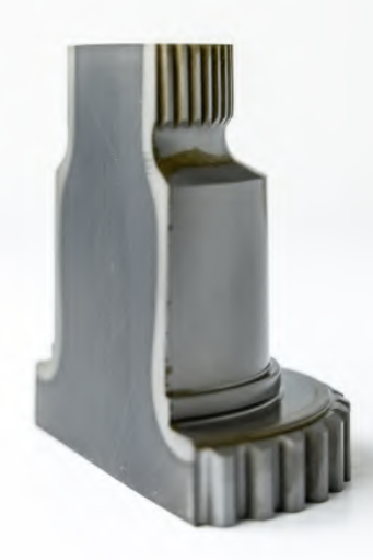
Eje cementado, seccionado y atacado químicamente, mostrando estrías de gran tamaño | Crédito de la imagen: Inductoheat
Los equipos de tratamiento térmico por inducción controlan de manera confiable diversos parámetros críticos para producir las propiedades metalúrgicas requeridas. Entre las más importantes se encuentran, la potencia suministrada y la frecuencia, el tiempo de calentamiento, la geometría y posición de bobina de inducción, sincronización, y el caudal del sistema de enfriamiento.
Cada una de estas variables desempeña un papel fundamental; incluso pequeñas desviaciones pueden modificar significativamente los resultados obtenidos. Por ejemplo, una ligera fluctuación en la potencia suministrada puede disminuir la profundidad de capa endurecida o generar perfiles de dureza no uniformes. En componentes para camiones, esto puede traducirse en una menor vida útil a fatiga bajo cargas elevadas. En vehículos tipo SUV o crossover, puede manifestarse como desgaste prematuro o incluso la falla del componente. Los equipos confiables garantizan que todas estas variables permanezcan estrictamente controladas ciclo tras ciclo y pieza tras pieza. De esta manera, el tratamiento térmico deja de ser un proceso susceptible a variaciones y se convierte en un proceso de manufactura repetible y controlado.
El Rol de la Bobina de Inducción
La bobina de inducción es el punto donde la energía interactúa directamente con el componente automotriz. Su diseño y estado de conservación influyen de manera directa en el calentamiento y, en consecuencia, en el patrón de endurecimiento obtenido. Una bobina correctamente diseñada y con un mantenimiento adecuado proporciona un acoplamiento electromagnético uniforme, una distribución uniforme del calor sobre la superficie y una penetración subsuperficial suficiente, permitiendo alcanzar la profundidad de capa endurecida y el perfil de dureza especificados.
Al recibir energía, la bobina de inducción genera un campo magnético. Esto provoca que el componente automotriz experimente un calentamiento por efecto Joule debido a la corriente inducida, fenómeno conocido como corrientes de Eddy. Los tiempos de calentamiento varían, generalmente basta unos pocos segundos para alcanzar la temperatura necesaria para la formación de austenita (rango de 750 a 850°C [1382–1562°F] dependiendo de la composición del acero).
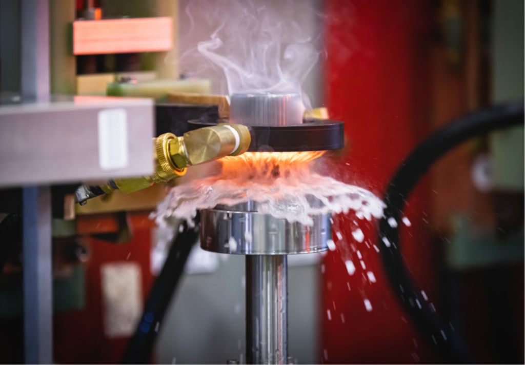
Bobina de inducción con sistema de enfriamiento por rociado integrado para el endurecimiento superficial | Crédito de la imagen: Inductoheat
Las bobinas de inducción son componentes de herramiental sujetos a desgaste. Con el tiempo, los ciclos térmicos repetitivos, la oxidación superficial, el desgaste y la fatiga mecánica reducen gradualmente su desempeño. Pequeñas modificaciones en la geometría de la bobina, su alineación o sus condiciones superficiales pueden alterar el campo electromagnético e introducir variabilidad. Lo más complejo es que estos cambios suelen producirse de forma gradual y no resultan visibles de inmediato. Una bobina puede continuar funcionando mientras afecta la distribución del calor sin que el problema sea evidente. Inspecciones periódicas, la limpieza y el reemplazo programado de las bobinas son fundamentales. En la manufactura automotriz de alto volumen, una gestión proactiva de las bobinas es esencial para mantener la estabilidad del proceso y garantizar la fiabilidad de los componentes tratados térmicamente.
Estabilidad de la Fuente de Alimentación
La fuente de alimentación del sistema de inducción controla la forma en que la energía se suministra a la bobina y, por lo tanto, al componente que será tratado térmicamente. Una salida de potencia estable es fundamental para lograr un calentamiento repetible y resultados metalúrgicos consistentes. La selección de la frecuencia de salida adecuada es esencial para equilibrar la profundidad de calentamiento requerida y la temperatura superficial del componente. En procesos de endurecimiento superficial, las frecuencias más utilizadas se encuentran en un rango de aproximadamente 1,000 Hz hasta 200 kHz. Aunque una sola fuente de alimentación no puede cubrir todo ese rango de frecuencias, la mayoría ofrece cierto grado de flexibilidad en cuanto a la frecuencia.
Las fuentes de alimentación proporcionan un suministro de energía preciso y programable a una frecuencia estable. Además, proporcionan una respuesta rápida ante las variaciones de carga a medida que la temperatura del componente automotriz aumenta, atraviesa el punto de Curie y alcanza la temperatura objetivo. Esta fuente de alimentación ofrece un rendimiento fiable durante ciclos de producción prolongados. Esto es fundamental cuando miles de componentes deben cumplir con especificaciones muy estrictas y con una variabilidad mínima. Si la fuente de alimentación presenta fluctuaciones, estas afectarán la velocidad de calentamiento y las propiedades finales de endurecimiento. Para los fabricantes, esto se traduce en piezas rechazadas y disminución de la rentabilidad.
Estos equipos requieren un programa de mantenimiento preventivo. Después de todo, un suministro confiable contribuye directamente tanto a la calidad como a la productividad. El personal debe:
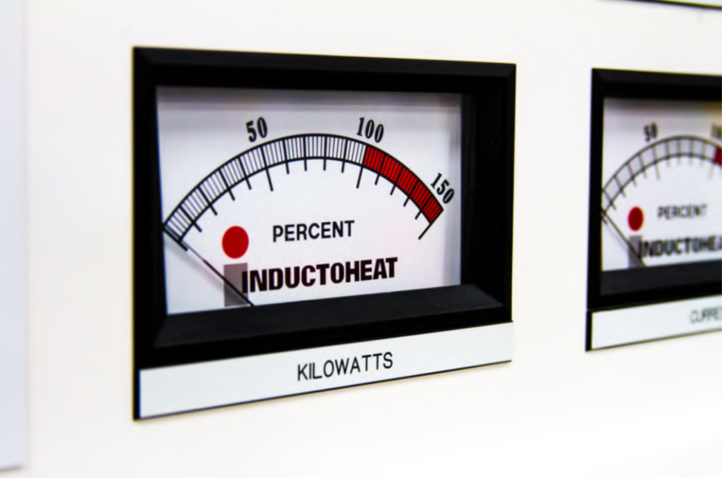
Medidor analógico de la Fuente de alimentación, % potencia–kilovatios | Crédito de la imagen: Inductoheat
Verificar periódicamente que las conexiones eléctricas de las barras conductoras y de las terminales de cableado estén firmes.
Revisar que todas las conexiones de las mangueras del sistema de enfriamiento estén firmes, especialmente a medida que las mangueras envejecen.
Verificar que todos los interruptores de protección funcionen correctamente.
Asegurarse de que el agua del sistema de enfriamiento esté limpia y comprobar su conductividad mensualmente.
Consultar el manual del fabricante para obtener más información.
El Temple: Finalización del Proceso
El calentamiento representa solo la mitad del proceso. El temple comienza una vez que el componente ha alcanzado la temperatura de austenización a la profundidad deseada. El medio de enfriamiento se rocía uniformemente sobre la superficie de la pieza, extrayendo el calor de forma rápida y controlada. Este enfriamiento permite la formación de martensita, proporcionando al componente automotriz una capa superficial endurecida. Todo el proceso se lleva a cabo dentro de límites de operación previamente establecidos para garantizar la repetibilidad del tratamiento térmico.
El fluido de temple suele ser agua con aditivo polimérico. Es fundamental mantenerlo a la temperatura adecuada y con la concentración especificada de polímero. El sistema de temple suministra este fluido con una sincronización precisa respecto al ciclo de calentamiento. Asimismo, la bomba y las válvulas deben garantizar caudales y presiones constantes. El intercambiador de calor del sistema elimina el exceso de calor del fluido de temple; de lo contrario, su temperatura aumentaría progresivamente después de cada ciclo.
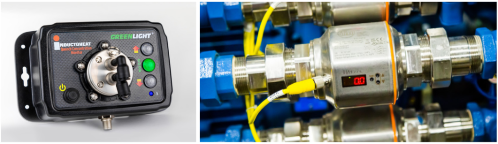
Monitor de concentración (izquierda) y válvulas de la tubería del sistema de temple (derecha) | Crédito de la imagen: Inductoheat
Con el paso del tiempo, parte del agua del fluido de temple se evapora, incrementando la concentración del polímero. Además, el fluido se contamina con residuos de aceite, virutas metálicas y otras impurezas. Los filtros tipo bolsa del sistema se saturan y los múltiples orificios de las boquillas de aspersión pueden obstruirse debido a la acumulación de incrustaciones y partículas. Por ello, el sistema de temple debe recibir mantenimiento periódico para garantizar un enfriamiento controlado y repetible. Solo así el proceso de tratamiento térmico puede completarse de manera consistente y confiable.
Confiabilidad basada en datos
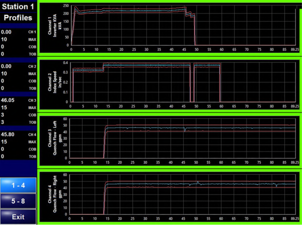
Los equipos de inducción deben operar con un alto nivel de precisión para lograr el tratamiento térmico especificado. Cuando estos sistemas incorporan monitoreo en tiempo real y adquisición de datos durante el proceso, se incrementa aún más la confianza en los resultados obtenidos. El monitoreo mediante “firmas” de proceso mide las múltiples variables del tratamiento térmico por inducción en cada ciclo. Esta “firma” puede incluir parámetros eléctricos como la potencia del inversor, la corriente, el voltaje y la frecuencia a lo largo del proceso. Asimismo, puede registrar la temperatura del medio de enfriamiento, el flujo y la presión del fluido de temple, así como la velocidad de escaneo de la máquina y la velocidad de rotación del husillo. Para cada una de estas variables se establece un rango de variación permitido, el cual se representa gráficamente en función del tiempo. Cualquier desviación fuera de estos límites durante el ciclo, hará que la máquina genere un fallo de proceso.
Firma de proceso del sistema QAS de Inductoheat, mostrando los límites superior e inferior permitidos y el registro de variables como la potencia del inversor (kVA), la velocidad de escaneo y el caudal de temple de los husillos izquierdo y derecho | Crédito de la imagen: Inductoheat
Esta funcionalidad constituye un elemento fundamental dentro de un sistema de aseguramiento de la calidad (QAS por sus siglas en inglés), ya que garantiza la confianza durante cada turno de producción. En el caso de componentes automotrices identificados mediante códigos de barras u otros marcadores únicos, también permite garantizar la trazabilidad de los componentes tratados térmicamente, almacenando la firma del proceso y asociándola a cada componente tratado térmicamente. Este paso permite obtener datos clave para aislar un lote de piezas si fuera necesario, evitando la necesidad de poner en cuarentena más unidades de las estrictamente necesarias.
Equipos Confiables. Mejores Componentes. Vehículos más Resistentes.
En toda la industria automotriz, desde camiones de servicio pesado hasta los SUVs y crossovers de uso cotidiano, el desempeño de un vehículo se construye capa por capa. A medida que las plataformas vehiculares continúan evolucionando, los procesos de tratamiento térmico deben avanzar al mismo ritmo de diseños de componentes cada vez más complejos. Contar con equipos de inducción confiables es fundamental para afrontar estos desafíos. Cada elemento del sistema debe operar con precisión y consistencia. El mantenimiento preventivo, incluido el reemplazo periódico de componentes sujetos a desgaste, como las bobinas de inducción, contribuye a mantener la estabilidad del proceso, obtener resultados consistentes y garantizar una producción confiable.
Para muchos fabricantes, preservar la confiabilidad también implica modernizar sus equipos existentes. Con frecuencia, los sistemas de inducción de mayor antigüedad pueden reacondicionarse mediante la incorporación de controles modernizados, nuevas fuentes de alimentación y componentes críticos actualizados, lo que permite prolongar su vida útil al tiempo que mejora el rendimiento y el tiempo de actividad. Asimismo, estos equipos pueden reacondicionarse para adaptarse a nuevos programas de tratamiento térmico.
Al invertir en tecnología de inducción confiable, los fabricantes pueden seguir produciendo componentes de alta calidad capaces de satisfacer las exigencias de los vehículos actuales.
Acerca del autor:
Aaron Goodwin Ingeniero de Desarrollo de Negocios Inductoheat
Aaron Goodwin cuenta con más de 32 años de experiencia en la industria del calentamiento por inducción, durante los cuales ha desempeñado diversos cargos técnicos en Inductoheat, ubicada en Madison Heights, Michigan. Actualmente se desempeña como Ingeniero de Desarrollo de Negocios, brindando soporte técnico tanto al equipo de ventas como de ingeniería. Entre sus principales responsabilidades se encuentra la dirección del equipo de simulación mediante análisis por elementos finitos (FEA) para el diseño de bobinas y procesos de calentamiento por inducción.
Además, Aaron colabora con las empresas hermanas del grupo Inductotherm alrededor del mundo, impulsando el desarrollo tecnológico, el intercambio de conocimientos y la implementación de soluciones enfocadas en las necesidades de los clientes.
Reliable induction heat treating depends on more than metallurgy — it requires precise, repeatable performance from every part of the induction system. In this Technical Tuesday installment, Aaron Goodwin, business development engineer for Inductoheat, explores how induction coils, power supplies, quench systems, and real-time process monitoring work together to consistently achieve the hardness, case depth, and microstructure demanded by today’s automotive components. Learn how equipment reliability, preventive maintenance, and process control help manufacturers reduce variability, improve quality, and keep production running efficiently.
This informative piece was first released in Heat Treat Today’sAugust 2026 Annual Automotive Heat Treating print edition.
There is a critical partnership between an automotive component’s design and its heat treat requirement. In modern vehicle manufacturing — whether trucks, SUVs, or crossovers — the margin for error is very small. Components like axles, gears, shafts, and other engine/drivetrain elements are subjected to demanding loads, high torque, and complex operating conditions. These vehicles must balance durability, efficiency, quiet operation, and performance. They also need to successfully handle a wide range of driving scenarios, from stop-and-go urban traffic to towing, off-road use, and long-distance travel.
Across these vehicle platforms, one reality remains constant. While material selection and engineering design are critical, consistency and reliability of the heat treating process determine whether components perform as intended in real-world conditions. Induction heating for case hardening of automotive components is a common choice among design engineers, and reliable induction heating equipment is key.
From the induction coil to the power supply and the quench system, each must operate with precision and repeatability for every cycle. Induction case hardening depends on tightly controlled variables working in harmony. When performance is stable, quality heat treated components follow. When it is not, variability is introduced and with it risk.
The Link Between Induction Equipment and Metallurgy
Sectioned and etched case-hardened shaft with large splines | Image Credit: Inductoheat
Heat treated components are evaluated based on hardness, case depth, and microstructure of the steel after processing. Each component has a heat treat specification that defines these metrics. Some components require shallow case depths while others have very deep case. Shallow case is needed for surface wear resistance, while deep case is specified for strength under high torsional loads, and there are scenarios in between.
Induction heat treatment equipment reliably executes several tightly controlled variables to produce the required metallurgical properties. Key variables include power output and frequency, heating time, coil geometry and position, quench timing, and flow rates.
Each variable plays a critical role: even small deviations can significantly alter results. A slight fluctuation in power delivery, for example, may reduce case depth or create uneven hardness profiles. In truck components, this could result in reduced fatigue life under high loads. In a crossover or SUV, it may show up as premature wear or component failure. Reliable equipment ensures that these variables remain tightly controlled cycle after cycle, part after part. It transforms heat treating from a “variable process” into a repeatable, engineered system.
The Role of Induction Coil
The induction coil is where the energy meets the automotive component. Its design and condition directly influence heating and resulting hardness case patterns. A well-designed and properly maintained coil provides consistent electromagnetic coupling, uniform heat distribution along the surface, and sufficient penetration sub-surface for creating required case depths and hardness profiles.
When energized, the induction coil produces a magnetic field. From this, the automotive component begins to experience Joule heating from induced current, known as eddy currents. Heat times vary but are often only a few seconds in duration to reach the temperature required for the formation of austenite (range of 750–850°C [1382–1562°F], depending on chemical composition of steel).
Induction scan coil with integrated spray quench for case hardening | Image Credit: Inductoheat
Induction coils are perishable tooling components. Over time, thermal cycling, surface oxidation, and degradation, along with mechanical fatigue can reduce performance. Minor changes in coil geometry, alignment, or surface conditions can alter the electromagnetic field and introduce variability. What makes this especially challenging is that these changes are often gradual and not immediately visible. A coil may continue operating while quietly affecting heat distribution. Routine inspection, cleaning, and scheduled replacement are essential. In high-volume automotive manufacturing, proactive coil management is critical to maintaining process stability and reliably heat treated components.
Power Supply Stability
The induction power supply governs how energy is delivered to the coil and thus the component being heat treated. A stable output of power is critical for repeatable heating and consistent metallurgical results. Selection of the proper output frequency is important to balance the required depth of heating and the surface temperature of the component. For case hardening, the most common frequencies utilized fall in the range of 1,000 Hz up to 200 kHz. While a single power supply cannot cover this entire frequency range, most will provide some range of frequency flexibility.
Power supplies have precise and programable energy delivery at a stable frequency. They provide rapid response to variations in load as the temperature of the automotive component increases, passes through the curie point, and reaches the target temperature. This power supply gives reliable performance across long production runs. This is important when thousands of components must meet specifications in a narrow margin of variability. If a power supply introduces fluctuations, these will affect the heating rates and final hardened properties. For manufacturers, this leads to scrap parts and reduced profitability.
Power supply analog meter, % power–kilotwatts | Image Credit: Inductoheat
These work horses need scheduled maintenance. After all, reliable power delivery directly supports both quality and productivity. Personnel must:
Periodically check the power supply for tight electrical connections on bus work and wire terminals.
Check all cooling water hosing connections for tightness as the hoses age.
Verify that all protection switches are working.
Ensure that the cooling system’s water is clean and check its conductivity monthly.
Refer to the manufacturer’s manual for more information.
Quenching: Completing the Process
Heating is only half of the equation. The quenching process is initiated after the component has reached its austenitizing temperature at the desired depth. Quench fluid is sprayed uniformly onto the surface of the component, which removes heat in a rapid and controlled manner. This produces the formation of martensite giving the automotive component a case-hardened surface layer. All of this is done within proper limit set points to produce repeatable heat treated components.
Quench fluid is typically water with polymer additive. It needs to be maintained at the appropriate temperature and with the required percentage of polymer quench additive. The quench system delivers it with precise timing relative to heating. The pump and valves must provide consistent flow rates and pressures. The heat exchanger in the quench system will remove excess heat from the quench fluid. Otherwise, the temperature of the fluid will continue rising after each cycle.
Over time, quench water evaporates raising the concentration of polymer quench. It also becomes contaminated with oily residue, metal chips, and more. Quench system bag filters become full, and the many orifices of quench spray devices get clogged with scale and debris. The quench system needs to be maintained to ensure that cooling is controlled and repeatable. This completes the heat treating process with consistency and reliability.
Data-Driven Reliability
Induction equipment must function with precision to achieve the required heat treatment. When this equipment includes real-time monitoring and data collection during the process, further confidence is provided. Signature monitoring measures the many aspects of induction heat treatment for every cycle. This “signature” can record electrical parameters like inverter power, current, voltage, and frequency over the process time. It can also include quench fluid temperature, flow, and pressure, along with machine scan speed and spindle rotation speed. Each of these is given a percentage of permitted variation, graphed over time. Any deviation outside of these boundaries during the cycle, and the machine will initiate a process fault.
Inductoheat QAS process signature with high/low boundaries; graphing interverter KVA scan speed, quench flow-left spindle, quench slow-right spindle | Image Credit: Inductoheat
This can be an important part of a quality assurance system (QAS) and ensure confidence during each production shift. For automotive components with barcodes or other unique markings, traceability becomes possible, saving the process signature from the machine and assigning it to the heat treated component. This step can provide critical data to isolate a batch of parts should the need arise, avoiding the tendency to quarantine more pieces than necessary.
Across the full spectrum of vehicle manufacturing, from heavy-duty trucks to everyday SUVs and crossovers, performance is built layer by layer. As vehicle platforms continue to evolve, heat treating processes must keep pace with increasingly complex component designs and performance requirements. Reliable induction equipment is essential to meet these challenges. Each aspect must operate with precision and consistency. Routine maintenance, including the replacement of wear items such as induction coils, helps ensure process stability, consistent results, and dependable production.
For many manufacturers, maintaining reliability also means modernizing existing equipment. Aging induction systems can often be rebuilt with updated controls, power supplies, and critical components, extending service life while improving performance and uptime. They can also be re-tooled for new heat treat programs.
By investing in induction equipment, manufacturers can continue producing high-quality components that support the demands of today’s vehicles.
About The Author:
Aaron Goodwin Business Development Engineer Inductoheat
Aaron Goodwin has over 32 years of experience in the induction heating industry, having held a variety of technical positions with Inductoheat in Madison Heights, Michigan. In his current role as business development engineer, Aaron provides technical support to both sales and engineering, with responsibilities that include leading the finite element analysis (FEA) simulation team for coil and process design. Aaron also collaborates with global sister companies throughout the Inductotherm Group, supporting technology development, knowledge sharing, and customer-focused solutions worldwide.
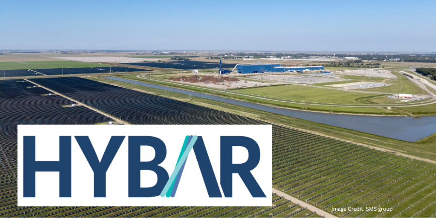
Hybar LLC, a U.S. steel producer, is adding a second continuous minimill at its Osceola, Arkansas, operation that will integrate electric arc furnace (EAF) melting, ladle refining, continuous casting, induction equalization, and rolling to increase reinforcing bar production by 630,000 short tons annually.
SMS group will supply the CMT® 550 mill, which will be installed alongside Hybar’s existing CMT® 550 operation, creating a twin-mill configuration that will share existing site infrastructure. Groundbreaking is expected in late 2026, with startup scheduled approximately 24 months later.
The meltshop will feature an EAF based on SMS group’s EDGE DC design platform and a twin ladle furnace station. An X-Pact AURA electrical power system will supply the melting unit, which is designed for production rates exceeding 80 tons per hour.
The mill will connect steelmaking, casting, and rolling in a continuous production process. A high-speed, single-strand endless caster will connect the meltshop to the rolling mill through an induction equalization furnace, reducing the need for conventional fossil-fuel-fired reheating between casting and rolling.
The new facility will produce reinforcing bars ranging from 12.4 to 35 millimeters and will include provisions for future installation of vertical compact coiling technology. The rolling mill will include 14 housing-less stands and a six-pass high-speed finishing block, as well as laser measurement equipment for dimensional verification and process control.
The project will also incorporate plant-wide acquisition of real-time production data. The information will feed a digital platform designed to support equipment monitoring, operational analysis, and machine-learning models.
The second mill will use infrastructure associated with Hybar’s existing operation, including access to the site’s 105-megawatt solar installation and 160-megawatt-hour battery storage system. The configuration is intended to reduce energy us and emissions compared with conventional minimill production.
“Building on the success of our first CMT® 550 mill at Hybar’s Osceola site to produce long products, we see huge potential to expand our capacities here at Osceola by combining logistics and labor expertise already on-site with this CMT® twin solution,” said David Stickler, CEO of Hybar. “This enables us to effectively respond to the increasing demand for green long production by taking advantage of shared utility costs.”
Press release is available in its original form here.