The Heat Treat Doctor® ha vuelto para ofrecer sabios consejos a los lectores de Heat Treat Today y para responder a suspreguntas sobre el tratamiento térmico, brazing, sinterizado y otros tipos de procesamiento térmico, así como preguntassobre metalurgia, equipos y problemas relacionados con los procesos.
The Heat Treat Doctor® has returned to offer sage advice to Heat Treat Today readers and to answer your questions about heat treating, brazing, sintering, and other types of thermal treatments as well as questions on metallurgy, equipment, and process-related issues.
This article was originally published inHeat Treat Today‘sSeptember 2024 People of Heat Treat print edition.
El temple es un paso fundamental en el proceso de tratamiento térmico. Y si bien el especialista en tratamiento térmico suele tener varias opciones disponibles, existe un delicado equilibrio entre lo que está disponible para nosotros y cómo podemos optimizar sus características de rendimiento para cumplir con los requisitos/especificaciones de nuestros clientes. Se deben tener en cuenta cuidadosamente el material, el diseño de la pieza (geometría), los requisitos previos y posteriores de manufactura, la carga, el cambio dimensional permitido (es decir, la distorsión) y el proceso como tal. Conozcamos más.
Medios de temple: una breve Descripción
Los medios de temple actuales ofrecen una amplia gama de capacidades que, en algunos casos, se traslapan. Sin embargo, en un nivel fundamental, la función de un medio de temple es extraer calor de la superficie de la pieza para cumplir con una velocidad crítica de enfriamiento especificada y con ello lograr la microestructura necesaria para lograr las propiedades mecánicas y físicas requeridas. En el temple de aceros, por ejemplo, se debe evitar pasar por la “nariz” de la curva de transformación-tiempo-temperatura (TTT) si el resultado final deseado es una microestructura martensítica (o bainítica). Por el contrario, la velocidad de enfriamiento para un proceso de normalización requiere enfriamiento “al aire”, un término que a menudo se malinterpreta y que abordaremos en una discusión futura.
Figura 1. Medios de Temple comunes y su efecto en la distorsión (1)
Sin embargo, un medio de temple (Figura 1) es más que solo su velocidad de enfriamiento. Los medios de temple deben ser estables durante su vida útil, especialmente con respecto a la degradación (por ejemplo, oxidación), ser seguros, ser fáciles de arreglar y mantener, tener un alto punto de vaporización, idealmente no interactuar con la superficie de la pieza, usarse dentro de su rango de rendimiento óptimo, tener una larga vida útil, eliminarse fácilmente mediante limpieza después del temple y ser rentables.
A manera de una caracterización muy amplia, los medios de temple se pueden dividir en las siguientes categorías generales:
Medios de temple líquidos (p. ej., a base de agua, aceites, polímeros, sales fundidas y metales fundidos)
Medios de temple gaseosos (p. ej., aire, nitrógeno, argón, hidrógeno, vapor, dióxido de carbono, dióxido de azufre, gases reductores, atmósferas protectoras sintéticas o generadas, gases a alta presión)
Medios de temple sólidos (p. ej., dados de prensa enfriados, placas y polvos)
Medios de medios mixtos (p. ej., temple por aspersión, lechos fluidizados)
Figura 2. Diagrama de Ishikawa (también conocido como de pescado) de las variables de temples (1)
Selección del medio de temple óptimo
Contact us with your Reader Feedback!
Se deben tener en cuenta varios factores al seleccionar el mejor medio de temple. A continuación, se enumeran algunos de los aspectos importantes a tener en cuenta al seleccionar el medio adecuado (Figura 2):
Material: composición química, templabilidad, forma (p. ej., barra, placa, forja, fundición), tipo (p. ej., forjado, sinterizado) y limpieza, por nombrar algunos
Geometría/diseño de la pieza: forma, tamaño, peso, complejidad
Estado de laminación o tratamiento térmico previo: recocido, normalizado, preendurecido, relevado de esfuerzos
Estado de tensión: el efecto acumulativo de las operaciones de laminación y las operaciones de fabricación del cliente antes del tratamiento térmico
Carga: canastillas (aleación, compuesto C/C, placas de grafito, etc.)
Parámetros del proceso: temperatura, tiempo, precalentamiento
Selección del equipo: ¿es óptimo o simplemente adecuado para el trabajo?
Medio(s) de temple disponibles: sus limitaciones y ventajas
Es importante hablar brevemente aquí sobre dos aspectos del proceso de selección del medio de temple. Primero, observar la diferencia entre dureza y templabilidad (que analizaremos con más detalle en el futuro). Los tratadores térmicos tienden a centrarse en la dureza (ya que podemos medirla fácilmente en nuestro taller), pero la templabilidad es una consideración crítica en la selección del medio de temple. La templabilidad es una propiedad del material independiente de la velocidad de enfriamiento y dependiente de la composición química y el tamaño del grano. Cuando se evalúa mediante pruebas de dureza, la templabilidad se define como la capacidad del material bajo un conjunto dado de condiciones de tratamiento térmico para endurecerse “en profundidad”. En otras palabras, la templabilidad se relaciona con la “profundidad de endurecimiento”, o el perfil de dureza obtenido, no con la capacidad de alcanzar un valor de dureza particular. Cuando se evalúa mediante técnicas microestructurales, la templabilidad se define (para aceros) como la capacidad del acero para transformarse parcial o completamente de austenita a un porcentaje definido de martensita.
Tabla 1. Valores medios e instantáneos del coeficiente de transferencia de calor (3)
En segundo lugar, se debe tener en cuenta tanto el valor medio como el instantáneo del coeficiente de transferencia de calor alfa (α) del medio de temple. Aunque la “potencia” máxima de temple se puede describir mediante el coeficiente de transferencia de calor instantáneo, el coeficiente de transferencia de calor promedio (Tabla 1) proporciona una mejor comparación relativa de los diversos medios de temple, ya que representa el valor del coeficiente de transferencia de calor en todo el rango de enfriamiento (desde el inicio hasta el final del temple). Es importante recordar que la capacidad de gestionar (no controlar) la distorsión es un delicado acto de equilibrio entre la extracción uniforme del calor y la transformación adecuada.
Tabla 2. Clasificación de los aceites de temple (1)
Un ejemplo común: selección de aceite de temple
Los factores importantes a tener en cuenta al seleccionar un aceite de temple, que son válidos en una forma ligeramente modificada para la mayoría de los medios líquidos, son: el tipo de medio (es decir, características del temple, datos de la curva de enfriamiento, nuevo y a lo largo del tiempo); velocidad de temple (consulte a Tabla 2); temperatura de uso; volumen efectivo del tanque de enfriamiento [es decir, la regla de un galón por libra de acero (8,4 L/kg)]; y los requisitos del cliente.
Los factores de diseño del tanque de temple también juegan un papel importante e involucran lo siguiente:
Volumen de aceite en el tanque de temple
Número de recirculadores o bombas
Ubicación de los recirculadores
Tipo de recirculadores (velocidad fija ovariable)
Disposición de los deflectores internos del tanque (tubos de aspiración, álabes de flujo direccional, etc.)
Diseño del elevador de temple (es decir, restricciones de flujo)
Dirección del flujo del temple (hacia arriba o hacia abajo a través de la carga)
Tamaño de la propela (diámetro, espacio libre en el tubo de aspiración)
Máximo incremento dela temperatura (diseño) delaceite después del temple
Altura del aceite sobre la carga
Intercambiador de calor: tipo, tamaño, tasa de extracción de calor (BTU instantáneos/minuto)
Tiempo de recuperación del aceite hasta el set point
Por último, se deben tener en cuenta factores como: la masa de la pieza; la geometría de la pieza (por ejemplo, secciones delgadas y gruesas, esquinas y barrenos afilados, perfil de los dientes del engrane, perfil de la rosca, etc.); espaciamiento de la pieza en la carga; velocidad de flujo efectiva a través del área de temple (vacía y con carga); estado de tensión de operaciones anteriores (de manufactura); operaciones de tratamiento térmico posteriores a realizar (si las hay); carga, incluidas las charolas, las canastillas y el herramental (material y diseño); y el material (composición química y templabilidad).
Reflexiones finales
El temple, considerado por muchos como un tema complejo y multifacético, es un asunto que los especialistas en tratamiento térmico deben supervisar y controlar constantemente. En futuras entregas, analizaremos muchos de los aspectos individuales del temple. Lo importante aquí es reconocer que, si se realiza correctamente, el temple (en cualquier forma) optimizará un tratamiento térmico determinado y ayudará a producir las piezas de la más alta calidad que exigen las industrias a las que prestamos nuestros servicios.
Referencias
Daniel Herring, Atmosphere Heat Treatment, Volume II: Atmospheres | Quenching | Testing (BNP Media Group, 2015).
Bozidar Liscic et al., Quenching Theory and Technology, Second Edition (CRC Press, Taylor Francis Group, 2010).
Daniel Herring, “A Review of Gas Quenching from the Perspective of the Heat Transfer Coefficient,” Industrial Heating, February 2006.
Sobre el autor
Dan Herring “The Heat Treat Doctor” The HERRING GROUP, Inc.
Dan Herring ha trabajado en la industria durante más de 50 años y ha adquirido una vasta experiencia en campos que incluyen ciencia de materiales, ingeniería, metalurgia, investigación de nuevos productos y muchas otras áreas. Dan es autor de seis libros y más de 700 artículos técnicos.
Para más información: Comuníquese con Dan en dherring@heat-treat-doctor.com.
For more information about Dan’s books: see his page at the Heat Treat Store.
Find Heat Treating Products And Services When You Search On Heat Treat Buyers Guide.Com
The Heat Treat Doctor® has returned to offer sage advice to Heat Treat Today readers and to answer your questions about heat treating, brazing, sintering, and other types of thermal treatments as well as questions on metallurgy, equipment, and process-related issues.
The Heat Treat Doctor® ha vuelto para ofrecer sabios consejos a los lectores de Heat Treat Today y para responder a suspreguntas sobre el tratamiento térmico, brazing, sinterizado y otros tipos de procesamiento térmico, así como preguntassobre metalurgia, equipos y problemasrelacionados con los procesos.
This article was originally published inHeat Treat Today‘sSeptember 2024 People of Heat Treat print edition.
Quenching is a critical step in the heat treating process. And while there are often several choices available to the heat treater, a delicate balance exists between what is available to us and how we can optimize its performance characteristics to meet our client’s requirements/specifications. Material, part design (geometry), pre-and post-manufacturing requirements, loading, allowable dimensional change (i.e., distortion), and the process itself must be taken into careful consideration. Let’s learn more.
Quenchants — A Brief Overview
Today’s quenchants offer a broad and, in some instances, overlapping range of capabilities. But at a fundamental level, the role of a quenchant is to extract heat from the part surface to meet a specified critical cooling rate and achieve the desired microstructure in the component part necessary to achieve the required mechanical and physical properties. In hardening of steels, for example, one must miss the “nose” of the time-temperature transformation (TTT) curve if the desired end-result is a martensitic (or bainitic) microstructure. By contrast, the cooling rate for a normalizing process requires cooling in “still air” — a term that is often misunderstood and which we will cover in a future discussion.
Figure 1. Common types of quenchants and their effect on distortion (See Reference 1)
However, a quenchant (Figure 1) is more than just its cooling rate. Quenchants should be stable over their service life, especially with respect to degradation (e.g., oxidation), be safe, be easy to service and maintain, have a high vaporization point, ideally not interact with the part surface, be used within their optimum performance range, have long life, be easily removed by cleaning after quenching, and be cost effective.
As a very broad-based characterization, quenchants can be divided into the following general categories:
Mixed media quenchants (e.g., mist or fog quenching, fluidized beds)
Figure 2. Ishikawa (aka fishbone) diagram of quenching variables (See Reference 1)
Selection of the Optimal Quench Medium
Contact us with your Reader Feedback!
Various factors must be taken into consideration when selecting the best quench medium. The following are some of the important considerations when selecting the proper quench medium (Figure 2):
Material — chemistry, hardenability, form (e.g., bar, plate, forging, casting), type (e.g., wrought, powder metal), and cleanliness to name a few
Part geometry/design — shape, size, weight, complexity
Mill or preheat treatment condition — annealed, normalized, pre-hardened, stress-relieved
Stress state — the cumulative effect of both mill operations and customer manufacturing operations prior to heat treatment
Process parameters — temperature, time, preheating
Equipment selection — is it optimal or simply adequate for the job?
Quench medium(s) available — their limitations as well as their advantages
It is important to talk briefly here about two aspects of the quench medium selection process. First, note the difference between hardness and hardenability (which we will discuss in more detail in the future). Heat treaters tend to focus on hardness (since we can easily measure it in our shops), but hardenability is a critical consideration in quench medium selection. Hardenability is a material property independent of cooling rate and dependent on chemical composition and grain size. When evaluated by hardness testing, hardenability is defined as the capacity of the material under a given set of heat treatment conditions to harden “in-depth.” In other words, hardenability is concerned with the “depth of hardening,” or the hardness profile obtained, not the ability to achieve a particular hardness value. When evaluated by microstructural techniques, hardenability is defined (for steels) as the capacity of the steel to transform partially or completely from austenite to a defined percentage of martensite.
Table 1. Average and instantaneous values of the heat transfer coefficient (See Reference 3)
Second, one must be aware of both the average and instantaneous value of the heat transfer coefficient alpha of the quench medium. Although the maximum quenching “power” may be described by the instantaneous heat transfer coefficient, the average heat transfer coefficient (Table 1) provides a better relative comparison of the various quenching media since it represents the value of the heat transfer coefficient over the entire range of cooling (from the start to the end of quenching). It is important to remember that the ability to manage (not control) distortion is a delicate balancing act between uniform heat extraction and proper transformation.
A Common Example — Quench Oil Selection
Important factors to consider when selecting a quench oil, which hold true in a slightly modified form for most liquid quenchants, are: the type of quenchant (i.e., quench characteristics, cooling curve data — new and over time); quench speed (see Table 2); usage temperature; effective quench tank volume (i.e., the one gallon per pound of steel [8.4 L/kg] rule); and the client’s requirements.
Table 2. Classification of quench oils (See Reference 1)
Quench tank design factors also play an important role and involve the following:
Volume of oil in the quench tank
Number of agitators or pumps
Location of agitators
Type of agitators (fixed or variable speed)
Internal tank baffle arrangement (draft tubes, directional flow vanes, etc.)
Quench elevator design (i.e., flow restrictions)
Quenchant flow direction (up or down through the load)
Propeller size (diameter, clearance in draft tube)
Maximum (design) temperature rise of the oil after quenching
Finally, consideration must be given to factors such as: part mass; part geometry (e.g., thin and thick sections, sharp corners and holes, gear tooth profile/modulus, thread profile, etc.); part spacing in the load; effective flow velocity through the quench area (empty and with a load); stress state from prior (manufacturing) operations; post heat treat operations to be performed (if any); loading including the grids, baskets, and fixture (material and design); and the material (chemistry and hardenability).
Final Thoughts
Quenching, considered by many to be a complex and multi-faceted subject, is one heat treaters must constantly monitor and control. In future installments we will be discussing many of the individual aspects of quenching. What is important here is to recognize that done correctly, quenching (in whatever form) will optimize a given heat treatment and help produce the highest quality parts demanded by the industries we serve.
References
Daniel Herring, Atmosphere Heat Treatment, Volume II: Atmospheres | Quenching | Testing (BNP Media Group, 2015).
Božidar Liščić et al., Quenching Theory and Technology, Second Edition (CRC Press, Taylor Francis Group, 2010).
Daniel Herring, “A Review of Gas Quenching from the Perspective of the Heat Transfer Coefficient,” Industrial Heating, February 2006.
About the Author
Dan Herring “The Heat Treat Doctor” The HERRING GROUP, Inc.
Dan Herring has been in the industry for over 50 years and has gained vast experience in fields that include materials science, engineering, metallurgy, new product research, and many other areas. He is the author of six books and over 700 technical articles.
In this episode of Heat TreatRadio,Doug Glenn discusses the hardenability of materials with guest Michael Mouilleseaux, general manager at Erie Steel LTD. Michael walks us through how to interpret hardenability charts and provides detailed insights on reading these charts, including addressing the importance of understanding the nuances of complicated part geometry.
Below, you can watch the video, listen to the podcast by clicking on the audio play button, or read an edited transcript.
The following transcript has been edited for your reading enjoyment.
Understanding a Hardenability Chart (01:59)
Doug Glenn: What I’d like to do is talk through this chart and learn how to read this a little bit better. And I’d like to ask questions about it because I’m not familiar with this, and I’m sure there are going to be some listeners and viewers who aren’t familiar with it. This will be just a quick tutorial on how to read these charts.
Go to the upper, right-hand corner. First off, SAE 4320H is the grade of the steel that we’re talking about?
The Heat Treat Lunch & Learn crew: Doug Glenn, Publisher of Heat Treat Today; Michael Mouilleseaux, General Manager at Erie Steel LTD.; Bethany Leone, Managing Editor of Heat Treat Today Use this chart to follow along with the conversation. Source of chart: Erie Steel, Ltd.
Michael Mouilleseaux: Correct.
Doug Glenn: Then the table right below that you’ve got percentage C (carbon). Is Mn manganese?
Michael Mouilleseaux: Manganese.
Doug Glenn: Thank you very much. Silicon, nickel, chrome, moly. My question is about those ranges. Is this basically saying the percentage carbon on the far left in 4320H goes anywhere from 0.17–0.23?
Michael Mouilleseaux: That is correct.
Doug Glenn: Okay. So that’s variability right there. All of those are basically telling you what the ranges are in those alloys in this grade of steel?
Michael Mouilleseaux: That is correct.
Doug Glenn: Then you go down to the top columns of this table below, and it says “Approximate diameter of rounds with same as quenched HRC in inches.” Right?
Approximate diameter of rounds with same as quenched HRC in inches Source: Erie Steel, Ltd.
Michael Mouilleseaux: Yeah. Essentially, the first three rows are for water quenching. And the bottom three are for oil quenching.
Doug Glenn: If you go over to the second major column called “Location in round,” what’s the size of the round we’re working on here?
Michael Mouilleseaux: It can vary. Go down to where it says, “Mild Oil Quench,” then left to “Surface,” then left then go to “2 inches.” Then, go straight down to the bottom, and that’s approximately J5. So, the “Distance from Quenched End — Sixteenths of an Inch” is Jominy position 5.
Michael Mouilleseaux: If you go to Jominy position 5 on the left-hand chart, you can see the hardness limits for that; the maximum is Rockwell C 41, and the minimum is Rockwell C 29. So, the chemistry can vary provided the hardenability at J5 is 29–41.
Doug Glenn: That’s the acceptable range?
Michael Mouilleseaux: That’s the acceptable range. That’s one way of looking at it. The chemistry would allow you to do that.
Now, go back to the chart on the right-hand side and to “Surface,” move down one row to “¾ radius from center,” and go left to two inches. Moving down from there you see that is Jominy position 8. So, the surface of a two-inch round is Jominy position 5, and the ¾ radius is Jominy position 8.
If you go to the hardness chart on the left-hand side, that says that if you had a two-inch round of 4320H, and it was oil quenched, and you check the hardness at ¾ radius, then the expectation is that it would be 23–34.
Now, go back to the same chart that we were just at, and go to the “Center” row of “Mild oil quench.” Continue left to two inches, and that’s J12. Go back to the left-hand chart, and J12 is 20–29 in the center of the part.
So, the surface of the part could be 41, ¾ radius, center of the part would be 34, and the center of the part would be 29.And that would all meet the criteria.
Doug Glenn: The maximum for J5 would be 41.But at J12 you could get a 20 in the middle.
Michael Mouilleseaux: Right. That is one way to look at this chart. But there is another way.
Notice that it says “rounds.”There are some nuances to having flats and rectangles because, if you think about it, for the cross-sectional area of a rectangle, the hardenability is going to be determined by the direction that it is thinnest, not by the direction that it is thickest.
Take a gear tooth, for example: in the chart that we just made up the gear teeth, the root of the gear was about a half inch, just slightly more; and if we go to this same chart, go to “Center” of “Mild oil quench,” and then go to a “0.5 inch,” and when you go straight down, that’s the J3.
Is a gear necessarily a round? Of course, the answer to that is no. So, in complex shapes you can use this data, but you have to interpolate it in order to understand it.
To some extent, the first time you run this, you’re going to say, “I have a gear, and the root is a half inch across. And I know that the J3 is 40. And I’ll run this part, and I’ll section it and I’ll measure it and it’s 40. And I’ll say that’s a good approximation of that.” And experientially, you build confidence in this, that is, it’s your operation, your quenching operation, and your components. It allows you to interpolate these, and they become extremely useful.
So, is it definitive? No. Is it useful? Yes.
Doug Glenn: It gives you a ballpark, right? I mean, it’s giving you something, maybe guardrails.
Michael Mouilleseaux: It gives you a ballpark; it gives you guardrails. And I can tell you that after having run gear product in the same equipment for ten years, I can say that it’s definitive. I can say that if I have this hardenability, and I get this hardenability number for this heat, and these gears are made from this heat of steel, and it has a J3 of 42. If I’m at 38, I know something is going on other than just hardenability. And, at that point, I would suspect my heat treat operation.
Doug Glenn: Yeah. I have one more question about this chart: On the bottom right part of the graph there are two plot lines on there. What do those represent? I was thinking one represented the water quench and the bottom one represents the oil quench.
Plot lines representing maximum hardenability and minimum hardenability Source: Erie Steel, Ltd.
Michael Mouilleseaux: The top one represents the maximum hardenability. And the lower the lower one represents the minimum hardenability.
Doug Glenn: That’s your band. Okay. Those are basically your values over on the left-hand side then. Very good.
I don’t know about you, but I found that helpful. I really didn’t ever know how to read these tables. So, maybe someone else will find that useful. Thanks, Michael. I appreciate your expertise.
Michael Mouilleseaux: It’s been my pleasure.
About The Guest
Michael Mouilleseaux General Manager at Erie Steel, Ltd. Sourced from the author
Michael Mouilleseaux is general manager at Erie Steel LTD. Mike has been at Erie Steel in Toledo, OH, since 2006 with previous metallurgical experience at New Process Gear in Syracuse, NY, and as the Director of Technology in Marketing at FPM Heat Treating LLC in Elk Grove, IL. Having graduated from the University of Michigan with a degree in Metallurgical Engineering, Mike has proved his expertise in the field of heat treat, co-presenting at the 2019 Heat Treat show and currently serving on the Board of Trustees at the Metal Treating Institute.
The future of heat treating requires new manufacturing solutions like robotics that can work with modular design. Yet so also does temperature monitoring need to be seamless to know how effectively your components are being heat treated — especially through being quenched.In this Technical Tuesday,learn more abouttemperature monitoring through the quench process.
Gas Carburization
Contact us with your Reader Feedback!
Carburizing has rapidly become one of the most critical heat treatment processes employed in the manufacture of automotive components. Also referred to as case hardening, it provides necessary surface resistance to wear, while maintaining toughness and core strength essential for hardworking automotive parts.
Figure 1. Typical carburizing heat treat temperature profile showing the critical temperature/time steps: (i) carburization, (ii) quench, and (iii) temper. (Source: PhoenixTM)
The carburizing process is achieved by heat treating the product in a carbon rich environment (Figure 1), typically at a temperature of 1562°F–1922°F (850°C–1050°C). The temperature and process time significantly influence the depth of carbon diffusion and other related surface characteristics. Critical to the process is a rapid quenching of the product following the diffusion in which the temperature is rapidly decreased to generate the microstructure, giving the enhanced surface hardness while maintaining a soft and tough product core.
The outer surface becomes hard via the transformation from austenite to martensite while the core remains soft and tough as a ferritic and/or pearlitic microstructure. Normally, carburized microstructures following quench are further tempered at temperatures of about 356°F (180°C) to transform some of the brittle martensite into tempered martensite to enhance ductility and grindability.
Critical Process Temperature Control
As discussed, the success of carburization is dependent on accurate, repeatable control of the product temperature and time at that temperature through the complete heat treatment process. Important to the whole operation is the quench, in which the rate of cooling (product temperature change) is critical to achieve the desired changes in microstructure, creating the surface hardness. It is interesting that the success of the whole heat treat process can rest on a process step which is so short (minutes), in terms of the complete heat teat process (hours). Getting the quench correct is not only essential to achieve the desired metal microstructure, but also to ensure that the physical dimensions and shape of the product are maintained (no distortion/warping) and issues such as quench cracking are eliminated.
Obviously, as the quench is so critical to the whole heat treat process, the correct quench selection needs to be made to achieve the optimum properties with acceptable levels of dimensional change. Many different quenchants can be applied with differing quenching performances. The rate of heat transfer (quench rate) of quench media in general follows this order from slowest to quickest: air, salt, polymer, oil, caustic, and water.
Technology Challenges for Temperature Monitoring
When considering carburization from an industry standpoint, furnace heat treat technology generally falls into one of two camps, embracing either air quench (low pressure carburization) or oil quench (sealed gas carburization/LPC with integral or vacuum oil quench). Although each achieves the same end goal, the heat treat mechanisms and technologies employed are very different, as are the temperature monitoring challenges.
To achieve the desired carburized product, it is necessary to control and hence monitor the product temperature through the three phases of the heat treat process. Conventionally, product temperature monitoring would be attempted using the traditional trailing thermocouple method. For many modern heat treat processes including carburization, the trailing thermocouple method is difficult and often practically impossible.1 The movement of the product or product basket from stage to stage, often from one independent sealed chamber to another (lateral or vertical movement), makes the monitoring of the complete process a significant challenge.
With the industry driving toward fully automated manufacturing, furnace manufacturers are now offering the complete package with full robotic product loading that includes shuttle transfer systems and modular heat treat phases to process both complete product baskets and single piece operations. Although trailing thermocouples may allow individual stages in the process to be measured, they cannot provide monitoring of the complete heat treat journey. Testing is therefore not under true normal production conditions, and therefore is not an accurate record of what happens in normal day to day operation.
Figure 2 shows schematic diagrams of two typical carburizing furnace configurations that would not be possible to monitor using trailing thermocouples. The first shows a modular batch furnace system where the product basket is transferred between each static heat treat operation (preheat, carburizing furnace, cooling station, quench, quench wash, temper furnace) via a charge transfer cart. The second shows the same heat treat operation but performed in a continuous indexed pusher furnace configuration where the product basket moves sequentially through each heat treat operation in a semi-continuous flow.
Thru-process temperature monitoring as a technique overcomes such technical restrictions. The data logger is protected by a specially designed thermal barrier, therefore, can travel with the product through each stage of the process measuring the product/process temperature with short, localized thermocouples that will not hinder travel. The careful design and construction of the monitoring system is important to address the specific challenges that different heat treat technology brings including modular batch and continuous pusher furnace designs (Figure 2).2
The following section will focus specifically on monitoring challenges of the sealed gas carburizing process with integral oil quench. Technical challenges of the alternative low pressure carburizing technology with high pressure gas quench have previously been discussed in an earlier publication.3
Monitoring Challenges of Sealed Gas Carburization — Oil Quench
Figure 3. “Thru-process” temperature monitoring system for use in a sealed carburizing furnace with integral oil quench — (3.1) Monitoring system entering furnace with thermocouple fixed to automotive gears, product test pieces (3.2) System exiting oil quench tank (3.3) System inserted into wash tank with product basket (Source: PhoenixTM)
Presently, the most common traditional method of gas carburizing for automotive steels is often referred to as sealed gas carburizing. In this method, the parts are surrounded by an endothermic gas atmosphere. Carbon is generated by the Boudouard reaction during the carburization process, typically at 1562°F–1832°F (850°C –1000°C). Despite the dramatic appearance of a sealed gas carburizing furnace, with its characteristic belching flames (Figure 3), from a monitoring perspective, the most challenging aspect of the process is not the heating, but the oil quench cooling. For such furnace technology, the historic limitation of “thru-process” temperature profiling has been the need to bypass the oil quench and wash stations, missing a critical process step from the monitoring operation. Obviously, passing a conventional hot barrier through an oil quench creates potential risk of both system damage from oil ingress and barrier distortion, as well as general process safety. However, the need to bypass the quench in certain furnace configurations by removing the hot system from the confined furnace space could create significant operational challenges, from an access and safety perspective.
Monitoring of the quench is important as ageing of the oil results in decomposition (thermal cracking), oxidation, and contamination (e.g. water) of the oil, all of which degrade the viscosity, heat transfer characteristics, and quench efficiency. Control of physical oil temperature and agitation rates is also key to oil quench performance. Quench monitoring allows economic oil replacement schedules to be set, without risk to process performance and product quality.
Figure 4. “Thru-process” temperature monitoring system oil quench compatible thermal barrier design: (1) Robust outer structural frame keeping insulation and inner barrier secure; (2) Internal thermal barrier — completely sealed with integral microporous insulation protecting data logger; (3) Mineral insulated thermocouples sealed in internal thermal barrier with oil tight compression fitting; (4) Multi-channel high temperature data logger; and (5) Sacrificial insulation blocks replaced after each run.
(Source: PhoenixTM)
To address the process challenges, a unique thermal barrier design has been developed that both protects the data logger in the furnace (typically three hours at 1697°F/925°C) and also protects during transfer through the oil quench (typically 15 mins) and final wash station (Figure 3). The key to the barrier design is the encasement of a sealed inner barrier with its own thermal protection with blocks of high-grade sacrificial insulation contained in a robust outer structural frame (Figure 4).
Quench Cooling Phases
Monitoring the oil quench in carburization gives the operator a unique insight into the product’s specific cooling characteristics, which can be critical to allow optimal product loading and process understanding and optimization. From a scientific perspective, the quench temperature profile trace, although only a couple of minutes in duration, is complex and unique. From a zoomed in quench trace (Figure 5) taken from a complete carburizing profile run, the three unique heat transfer phases making up the oil quench cool curve can be clearly identified:
Figure 5. Oil quench temperature profile for different locations on an automotive gear test piece shows the three distinct heat transfer phases: (1) film boiling “vapor blanket”, (2) nucleate boiling, and (3) convective heat transfer. (Source: PhoenixTM)
Film boiling “vapor Blanket”: The oil quenchant creates a layer of vapor (Leidenfrost phenomenon) covering the metal surface. Cooling in this stage is a function of conduction through the vapor envelope. Slow cool rate since the vapor blanket acts as an insulator.
Nucleate boiling: As the part cools, the vapor blanket collapses and nucleate boiling results. Heat transfer is fastest during this phase, typically two orders of magnitude higher than in film boiling.
Convective heat transfer: When the part temperature drops below the oil boiling point. the cooling rate slows significantly. The cooling rate is exponentially dependent on the oil’s viscosity.
From a heat treat perspective, the quench step relative to the whole process (hours) is quick (seconds), but it is probably the most critical to the performance of the metallurgical phase transitions and achieving the desired core microstructure of the product without risk of distortion. By being able to monitor the quench step, the process can be validated for different products with differing size, form, and thermal mass. As shown in Figure 6, the quench curve profile over the three heat transfer phases is very different for two different automotive gear sizes.
Figure 6. Oil quench temperature profile for different automotive gear sizes (20MnCr5 case hardening steel) with different thermal masses: Passenger Car Gear (2.2 lbs) and Commercial Vehicle Gear (17.6 lbs) (Source: PhoenixTM)
Summary
As discussed in this article, one of the key process performance factors associated with gas carburization is the control and monitoring of the product quench step. Employing an oil quench, the measurement of such operation is now very feasible as part of heat treat monitoring. Innovations in thru-process temperature profiling technology offer specific system designs to meet the respective application challenges.
References
[1] Dr. Steve Offley, “The light at the end of the tunnel – Monitoring Mesh Belt Furnaces,” Heat Treat Today, February 2022, https://www.heattreattoday.com/processes/brazing/brazing-technical-content/the-light-at-the-end-of-the-tunnel-monitoring-mesh-belt-furnaces/.
[2] Michael Mouilleseaux, “Heat Treat Radio #102: Lunch & Learn, Batch IQ Vs. Continuous Pusher, Part 1,” interviewed by Doug Glenn, Heat Treat Radio, October 26, 2023, audio, https://www.heattreattoday.com/media-category/heat-treat-radio/heat-treat-radio-102-102-lunch-learn-batch-iq-vs-continuous-pusher-part-1/.
[3] Dr. Steve Offley, “Discover the DNA of Automotive Heat Treat: Thru-process Temperature Monitoring,” Heat Treat Today, August 2023, https://www.heattreattoday.com/discover-the-dna-of-automotive-heat-treat-thru-process-temperature-monitoring/.
About the Author
Dr Steve Offley (“Dr O”), Product Marketing Manager, PhoenixTM
Dr. Steve Offley, “Dr. O,” has been the product marketing manager at PhoenixTM for the last five years after a career of over 25 years in temperature monitoring focusing on the heat treatment, paint, and general manufacturing industries. A key aspect of his role is the product management of the innovative PhoenixTM range of thru-process temperature and optical profiling and TUS monitoring system solutions.
Oil quenching can be a dirty phrase around the heat treat shop. But with vacuum, does it have to be?
This Technical Tuesday article was written by Don Marteeny, vice president of engineering at SECO/VACUUM Technologies,forHeat Treat Today’sNovember 2023 Vacuum Heat Treating print edition.
There are metallurgical advantages to oil quenching for which there are no gas quench substitutes, but for a time, those advantages only came bundled with some disadvantages that proved incompatible with a growing preference for vacuum processes. This drove vacuum oil quenching (VOQ) to evolve and improve, often faster than its reputation. VOQ has since matured into a convenient, safe, and economical choice, offering today’s vacuum heat treaters all the metallurgical advantages of oil quench without any of the compromises.
A Familiar Scene . . .
Don Marteeny
Vice President of Engineering
SECO/VACUUM TechnologiesContact us with your Reader Feedback!
When oil quenching is mentioned in the break room of any heat treat department, it’s a sure bet that those listening have very similar thoughts. With just the mere mention of oil, their thoughts carry them, not to memories of the first time they helped their dad change the oil in their car in the family garage, but instead to a row of furnaces belching flames from their doors. Next, they are sure to see one of the doors open, and the familiar sensation of hot air moves through their mind. They may – for a moment – expect the smell of salt air, the sand between their toes, and the sun from above.
For many heat treaters, this is but a momentary escape. Soon, the taste and smell of hot oil and metal return them to the moment, and they know they are standing next to a row of batch integral quench (aka, batch IQ or BIQ) furnaces.
It’s about then they will feel the heat of those flames at the end of this furnace line or by the transfer car, wiping the sweat from their brow with a sooty hand and anticipating a return to the break room for a cool drink of water.
Sound familiar? If so, you’re one of the hundreds of heat treaters who has had the pleasure of operating a tried-and-true atmosphere integral quench line; it faithfully does its job, hardening and case hardening steels where oil is the only heavy lifter that can do the job.
While heat treaters have been diligently pumping out oil hardened steels, furnace builders and OEMs alike have been trying to find ways to move away from oil to quenchants that, primarily, reduce distortion, but also that are cleaner, require less processing, and present a safer working environment. Despite their efforts working with modified quenchants – including high pressure gas quenching (HPGQ) in vacuum furnaces – oil quenching has proven robust, maybe even stubborn.
Does that mean we are stuck with the integral quench furnace and its fire-breathing ways? Not necessarily. . . .
Figure 2. D-Type double chamber for batch work processing with conventional loading over the oil quench
Source: SECO/VACUUM Technologies
An Invention Waiting on Improvement
The concept of a vacuum oil quenching furnace is nothing new. When first developed, it was unique because it combined the advantages of vacuum heat treating with the ability to oil quench. But at the time, they were an unlikely couple that never really got along as well as the atmosphere furnace with an oil quench tank.
Vacuum oil quench furnaces were expensive, had large footprints, and were not particularly reliable. Plus, if case hardening was required, low pressure carburizing was not particularly attractive as it was still in its infancy, at least compared to gas carburizing. So, VOQ stayed in the shadows, fulfilling limited roles where the application warranted the extra complication of vacuum. In the meantime, the integral quench furnace became the workhorse of choice, churning out oil and case hardened parts for industries worldwide.
HPGQ Drives Improvement in Vacuum Furnace Technology
Despite the success of the integral quench furnace, VOQ remained present, stirring in the shadows. In the meantime, vacuum furnace technology advanced through the development of high pressure gas quenching. The design and construction of a vacuum furnace lent itself to this application well and introduced a host of advantages, such as found in Maciej Korecki’s “Case Study of CMe-T6810-25 High Volume Production”:
• Decreased distortion
• Elimination of intergranular oxidation (IGO)
• No decarburization
Vacuum Furnaces Move from Niche to Standard Issue
In addition, these design developments supported the opportunity to case harden parts through the use of low pressure carburizing (LPC). Coupled with quenching pressures up to 25 bar, the HPGQ-equipped vacuum furnace became a real option for the heat treater interested in through hardening that did not require:
• Special atmosphere generation equipment (atmosphere generator)
• Lengthy furnace-conditioning cycles to assure the correct gas carburizing conditions as is typically necessary in the batch IQ furnace
• Post-heat treating surface cleaning in the form of washing or oxidation removal
VOQ Begins to Follow Suit
Still, vacuum and HPGQ were limited in their ability to serve in the role of hardening some steels when considering common geometries. This meant that, for those steels, oil remained the go-to quenching solution. As a result, the VOQ furnace became the furnace of choice.
It still required:
• Post-quench wash
• Aggressive oil circulation to minimize distortion
• Selection of the appropriate oil
• Careful fixture design
However, the advantages were too many to ignore. The fact that one could through harden steels like 8620 in a clean environment without the safety and cleanliness concerns inherent to integral quench furnaces was a huge advantage. And although furnace footprint remained a concern until the early 2000s, advancements in areas such as mixer design, vacuum pumps, and low vapor pressure quenching oils all contributed to decreasing the footprint and increasing the reliability of VOQ, making it an even more viable option. In more recent times, environmental concerns have also renewed attention to the VOQ furnace because of its vacuum capability.
Advantages include:
• Electric heating – no natural gas consumption
• Inert gas atmosphere or vacuum environment – no atmosphere generator needed • Zero CO2 emissions, even when case hardening using LPC
Figure 3. T-Type triple chamber for continuous batch work – oil quench or gas cooling/quenching with a separate chamber for preheating and semicontinuous operation
Source: SECO/VACUUM Technologies
Which Brings Us to Today
Vacuum oil quenching technology has progressed to overcome the challenges of yesteryear, and technological improvements have made it a flexible and configurable option for a heat treater’s current – and future – needs.
The VOQ is now available in configurations that provide both batch and semicontinuous options. This provides the opportunity to harden or case harden components with increased productivity and efficiency.
A common configuration offered is the two-chamber VOQ furnace as pictured in Figure 2. In this batch type configuration, common working zone sizes – such as 24″ x 24″ x 36″ or 36″ x 36″ x 48″ – are available with load capacities up to 2,650 lbs. A graphite-insulated hot zone provides the capability to achieve working temperatures up to 2400°F while providing the platform to case harden using LPC. This configuration also has the ability to conduct partial pressure heating using nitrogen. When quenching, the use of high-flow oil mixers promotes good oil mixing during quench to minimize distortion. This configuration can also cool in nitrogen above the oil in the quench tank, providing additional process flexibility.
In applications requiring higher productivity, a third preheating chamber can be added to the furnace system to provide the opportunity to preheat the furnace charge. The addition of the preheating chamber provides a semicontinuous operation as opposed to the batch operation provided by the two-chamber furnace. The result is a two times increase in throughput of the furnace system. Depending on the process requirements, production rates of up to 440 lb/hr are possible. The modern vacuum oil quench offers a versatile platform with a compact design capable of multiple processes and high production rates. The traditional two-chamber VOQ offers a batch platform capable of neutral and case hardening through the use of LPC. The three-chamber model provides similar options with the opportunity for high-capacity production through the addition of a preheating chamber with semicontinuous processing. Both demonstrate the advancements and the potential of this modern furnace as flexible, safe, and environmentally-friendly option in oil quenching.
Figure 4. An LPC process that yielded a net 1,322 lb (600 kg) load of gears with an effective case depth of 0.039 in (1 mm). This resulted in a throughput of 294 lb/hr (133 kg/hr). Slight adjustments to this process have rendered production of up to 440 lb/hr. (Source: Maciej Korecki, “Case Study of CMe-T6810-25”)
Source: SECO/VACUUM Technologies
About the Author: Don Marteeny has been vice president of Engineering for SECO/VACUUM Technologies for over five years. He is a licensed professional engineer and has been a leader at the company over the last several years filling project management and engineering leadership responsibilities. Don is a member of Heat Treat Today’s 40 Under 40 Class of 2021.
For more information: Contact Don at Don.Marteeny@secowarwick.com
Find heat treating products and services when you search on Heat Treat Buyers Guide.com
Thirsting for knowledge about quenching, but not sure where to start? Heat TreatToday has coalesced technical information across articles and podcast episodes from key experts, including significant quenching methods, innovative developments with quenching, and how to control temperature during the process.
Discover more about these three topics in today’s Technical Tuesday original content feature.
Monitor Quench Temperatures with Unique Thermal Barrier Designs
Automotive heat treating operations require repeatable operations to ensure that the composite parts within an automobile perform reliably. Steve Offley, also known as “Dr. O," the product marketing manager at PhoenixTM, outlines case studies of several temperature-critical operations to demonstrate how unique thermal barrier design for thru-process monitoring systems can solve temperature measuring problems. These processes include sealed gas carburizing into an integrated oil quench as well as LPC followed by transfer to a sealed high-pressure gas quench chamber.
Offley comments on the quenching process following LPC, saying, "During the gas quench, the [thermal] barrier [for temperature monitoring] needs to be protected from Nitrogen N2(g) or Helium He(g) gas pressures up to 20 bar." If you are facing heat treat processing with integrated quench, learn more about this temperature monitoring solution.
Intensive Quenching: An Answer for a "Greener" Heat Treat?
Gas furnaces have the potential to be a significant source of carbon emissions in many essential heat treat processes. However, an innovative approach combining induction through heating with intensive quenching could be one answer for greener heat treating, particularly for steel production.
In this article, Chris Pedder,Edward Rylicki, and Michael Aronov share that an “ITH + IQ” technique "eliminates, in many cases, the need for a gas-fired furnace when conducting through hardening and carburizing processes." A lot of this comes down to shortening the time it takes to perform this process, but there is so much more that the authors illuminate in their tests and graphs.
Drinking from a Firehose: Answering Your Quench Questions with a Thorough Radio Review
Stay afloat in a sea of quenching tips with this Heat TreatRadio review, summarizing three recent podcast episodes centered around quenching tips, techniques, and training — especially applying to the auto industry.
Explore the "green" process of salt quenching with Bill Disler of AFC-Holcroft, the topic of water in your quench tank with Greg Steiger of Idemitsu Lubricants America, and a broad review of auto industry quenching with Scott MacKenzie of Quaker Houghton, Inc.
On site at heat treat operations, gas-fired furnaces can be a significant source of carbon emissions. But depending on the desired heat treatment, an alternative approach that combines induction through heating and intensive quenching could be the “green ticket.” Learn about the ITH + IQ technique and discover how certain steels may benefit from this approach.
This Technical Tuesday article was composed by Edward Rylicki, Vice President Technology, and Chris Pedder, Technical Manager Heat Treat Products and Services, at Ajax TOCCO Magnethermic Corp., and Michael Aronov, CEO, IQ Technologies, Inc.It appears in Heat Treat Today's May 2023 Sustainable Heat Treat Technologiesprint edition.
Introduction
Chris Pedder, Technical Manager Heat Treat Products and Services, Ajax TOCCO Magnethermic Corp. Source: Ajax TOCCO Magnethermic Corp.
Induction heating is a green, environmentally friendly technology providing energy savings and much greater heating rates compared to other furnace heating methods. Other advantages of induction heating include improved automation and control, reduced floor space, and cleaner working conditions. Induction heating is widely used in the forging industry for heating billets prior to plastic deformation. Induction heating is also used for different heat treatment operations such as surface and through hardening, tempering, stress relieving, normalizing, and annealing. However, the amount of steel products subjected to induction heating in the heat treating industry is much less compared to that processed in gas-fired furnaces.
Contact us with your Reader Feedback!
Gas-fired heat treating equipment is a major source of carbon emissions in the industry. As shown in Reference 1, induction through heating (ITH) followed by intensive quenching (IQ) (an “ITH + IQ” technique) eliminates, in many cases, the need for a gas-fired furnace when conducting through hardening and carburizing processes — the two most widely used heat treating operations for certain steel parts. Eliminating gas-fired furnaces will result in significant reduction of carbon emissions at on-site heat treat operations.
Dr. Michael Aronov, CEO, IQ Technologies, Inc. Source: Ajax TOCCO Magnethermic Corp.
The goal of this article is twofold: 1) to evaluate carbon emissions generated during through hardening of steel parts and carburizing processes when conducted in gas-fired furnaces, and 2) to discuss how these emissions can be reduced to zero using the ITH + IQ process.
Evaluation of Carbon Emissions for Through Hardening and Carburizing Processes
Ed Rylicki, Vice President Technology, Ajax TOCCO Detroit Development & Support Center Source: Ajax TOCCO Magnethermic Corp.
Most through hardening and carburizing operations for steel parts are conducted in batch and continuous integral quench gas-fired furnaces. Assumptions made for evaluating CO2 emissions produced by a typical integral quench furnace are presented in Table 1. Note: The values of carbon emissions presented Table 1 are conservative since they don’t consider the amount of CO2 produced by furnace flame screens and endothermic gas generators used to provide a controlled carburizing atmosphere in the furnace. Also, it’s assumed that the furnace walls are already heated through when loading the parts, so there are no heat losses associated with the thermal energy accumulated by the furnace walls.
Table 1. Assumptions for calculating of carbon emissions by integral quench furnace Source: Ajax TOCCO Magnethermic Corp.
Emissions Generated During the Through Hardening Process
A furnace time/temperature diagram for the through hardening process considered is presented in Figure 1. Carbon emissions Ehard produced by the furnace considered during heating of the load to the austenitizing temperature prior to quenching are calculated by using the following equation,
(Equation 1) Ehard = k • Qhard
where:
■ k = the emission coefficient (equal to 0.050 • 10-3 kg per 1 kJ of released energy when burning natural gas (see Reference 2) ■ Qhard = thermal energy required for heating up the above load from ambient to the austenitizing temperature
A value of Qhard is calculated by the equation below,
■ M = load weight, kg ■ C = steel specific heat capacity (kJ/kg°C) ■ Ta = part austenitizing temperature (°C) ■ To = part initial temperature (°C) ■ Eff = furnace thermal efficiency (a ratio of the furnace thermal losses to the gross heat input)
From equations (1) and (2), the amount of carbon emissions produced by the above furnace during one hardening operation is 40.2 kg. To determine an annual amount of carbon emissions, calculate the number of hardening cycles per year (Nhard) run in the furnace. From Figure 1, a duration of one hardening cycle is 4 hours (3 hours for austenitizing of the parts plus 1 hour for quenching the parts in oil and unloading/loading the furnace). Thus, Nhard is equal to:
Nhard = 360 day • 24 hour • 0.85 / 4 hour = 1826
Figure 1 Source: Ajax TOCCO Magnethermic Corp.
Annual CO2 emissions from one integral quench batch gas-fired furnace are 40.2 • 1836 = 73,807 kg, or more than 73 t
Emissions Generated During Carburizing Process
A simplified furnace time/temperature diagram for the carburizing process considered is presented in Figure 2. Carbon emissions (Ecarb) produced by the above furnace during the carburizing process are calculated by the following equation,
(Equation 3)
Ecarb = k • Qcarb
where:
■ Qcarb = a thermal energy expended by the furnace during the carburizing process. A value of Qcarb amounts to two components:
(Equation 4)
Qcarb = Qcarb1 + Qcarb2
Qcarb in the following equation is:
■ Qcarb1 = energy required for heating up the load to the carburizing temperature
■ Qcarb2 = energy needed for maintaining the furnace temperature during the remaining duration of the carburization process (for compensation of the furnace thermal losses since the parts are already heated up to the carburizing temperature)
A value of Qcarb1 is calculated using equation (2) where the part carburizing temperature Tc is used instead of part austenitizing temperature Ta (see Table 1):
A value of Qcarb2 is a sum of the flue gas losses and losses of the thermal energy through the furnace walls by heat conduction. Qcarb2 is evaluated from the following considerations. Since the assumed furnace thermal efficiency is 65%, the furnace heat losses are equal to 35% of the gross heat input to the furnace. Hence, the furnace heat losses Qloss1 during the load heat up period (the first 3 hours of the carburizing cycle, see Figure 2) are the following:
Thus, the total amount of the thermal energy expended by the furnace during the carburizing cycle is Qcarb = 0.887 • 106 + 0.827 • 106 = 1.71 • 106 kJ. The total amount of the CO2 emissions from carburizing of the load in the furnace considered according to equation (3) is: Ecarb = 0.050 • 10-3 • 1.71 • 106 = 85.7 kg. To determine an annual amount of carbon emissions from one carburizing furnace, calculate the number of carburizing cycles run in the furnace per year. Per Figure 2, a duration of one carburizing cycle is 12 hour (1 hour for the furnace recovery plus 10 hour for carburizing of parts at 927°C plus 1 hour for quenching parts in oil and for unloading and loading the furnace). Thus, the number of carburizing cycles per year Ncarb is:
Ncarb = 360 day • 24 hr • 0.85 / 12 hr = 612
Figure 2 Source: Ajax TOCCO Magnethermic Corp.
Annual CO2 emissions from one integral quench batch carburizing furnace is about 85.7 • 612 = 52,448 kg, or more than 52 t.
Reducing Carbon Emissions Using the ITH + IQ Process
Reference 1 presents results of two case studies of the ITH + IQ process on automotive input shafts and drive pinions. The study was conducted with a major U.S. automotive part supplier. A two-step heat treating process was used for the input shafts, consisting of batch quenching parts in oil or polymer using an integral quench gas-fired furnace for core hardening followed by induction hardening. This two-step method of heat treatment is widely used in the industry for many steel products. It provides parts with a hard case and tough, ductile core.
Substituting the “ITH + IQ” method for the two-step heat treating process not only eliminates the batch hardening process, but also requires less alloy steel for the shafts that don’t require annealing after forging. Thus, in this case, applying the ITH + IQ technique eliminates two furnace heating processes for the input shafts, resulting in the reduction of the CO2 emissions to zero for the shafts’ heat treatment. Per client evaluation, as mentioned in Reference 1, the hardness profile in the intensively quenched input shafts was similar to that of the standard shafts. Residual surface compressive stresses in the intensively quenched shafts were greater in most cases compared to that of the standard input shafts, resulting in a longer part fatigue life of up to 300%.
Per Reference 1, the environmentally unfriendly carburizing process can be fully eliminated in most cases for automotive pinions when applying the ITH + IQ method and using limited hardenability (LH) steels that have a very low amount of alloy elements. A case study conducted for drive pinions with one of the major U.S. automotive parts suppliers demonstrates the intensively quenched drive pinions met all client’s metallurgical specifications and passed both the ultimate strength test and the fatigue test. It was shown that the part’s fatigue resistance improved by about 150% compared to that of standard carburized and quenched in oil drive pinions. In addition, distortion of the intensively quenched drive pinions is so low that no part straitening operations were required.
Conclusion
Coupling Ajax TOCCO’s induction through heating method with the intensive quenching process creates a significant reduction of CO2 emissions produced during heat treatment operations for steel parts. For the through hardening process, eliminating just one batch integral quench gas-fi red furnace will reduce carbon emissions by more than 73 ton per year. For the carburizing process, eliminating just one batch carburizing furnace will reduce carbon emissions by more than 52 ton per year. Note that for continuous gas-fired furnaces, the carbon emission reduction will be much greater due to higher continuous furnaces production rates (hence a much higher fuel consumption).
Per our experience, the ITH + IQ process can be applied to at least 20% of the currently through-hardened and carburized steel parts. Per two major heat treating furnace manufacturers in the U.S., there are thousands of atmosphere integral quench batch and continuous furnaces in operation in the U.S. That means hundreds of gas-fired heat treating furnaces can be potentially eliminated, drastically reducing carbon emissions in the U.S., supporting a lean and green economy.
Ed Rylicki has been in the induction heating industry for over 50 years. He is currently Vice President Technology at Ajax TOCCO Detroit Development & Support Center in Madison Heights, Michigan.
Mr. Chris Pedder has over 34 years of experience at Ajax Tocco Magnethermic involving the development of induction processes in the heat treating industry from tooling concept and process development to production implementation.
Dr. Michael Aronov has over 50 years’ experience in design and development of heating and cooling equipment and processes for heat treating applications. He is CEO of IQ Technologies, Inc. and a consultant to the parent company Ajax TOCCO Magnethermic.
Fundamentals of furnace maintenance sometimes fall between that tricky area of realizing their importance and getting pushed to the end of the to-do list. This original content piece shares tips to bring the fundamentals back to where they belong: at the top of the to-do list.
Ben Gasbarre President, Industrial Furnace Systems Gasbarre Thermal Processing Systems
Safety First | Whether the furnace is in operation, or it is having down time, proper safety measures must be in place. Personal protective equipment, proper shut down of power sources, and even the buddy system are topics taken in to consideration.
Asset Management System | Have up-to-date maintenance records available to any and all employees. "Ensuring important information, such as alloy replacements, burner tuning, or control calibration information, can help operations and maintenance personnel as they plan and assess future equipment needs," comments Ben Gasbarre, president industrial furnace systems at Gasbarre Thermal Processing Systems.
Cleaning | Reminders include: change filters on combustion blowers, clean things like burners and flame curtains, clean out endothermic gas lines, burn off manual probes at least once a week, etc.
Daniel Hill, PE Sales Engineer AFC-Holcroft Source: AFC-Holcroft
Rules and Regulations | The military and energy industries are sectors that have strict standards to follow. Different heat treating shops are using a software module to maintain furnace data, looking at data reports to make sure the furnace systems are running properly.
Timely Maintenance | Making a maintenance plan and then following it means that no tasks are overlooked or forgotten.
After Repairs and Adjustment | Make sure that after trouble shooting and performing repairs, the software generated reports are examined and that furnaces continue to be maintained. Daniel Hill, PE, sales engineer at AFC-Holcroft says, "This saves valuable time and resources, improves availability, and likely increases profitability."
Greg Steiger Senior Key Account Manager Idemitsu Lubricants America
Proper Levels of Sludge and Water Quench | Failing to keep the quench oil clean results in problems on surface finish. Maintain the quench from the start by filtering, cleaning, and replenishing to keep end product surfaces more acceptable.
Frequency of Sampling | "[The] more often a quench oil is analyzed, the easier it is to use the quench oil analysis as a tool in the proper care of a quench oil," explains Greg Steiger, senior key account manager at Idemitsu Lubricants America.
Regular Addition of Fresh Oil | Proper maintenance of quench oil will result in some loss through filtration. Be sure to replenish.
Find heat treating products and services when you search on Heat Treat Buyers Guide.com
Twice a month, Heat TreatToday publishes an episode of Heat TreatRadio, an industry-specific podcast that covers topics in the aerospace, automotive, medical, energy, and general manufacturing realms. Each episode provides industry knowledge straight from the experts.
Stay abreast of quenching tips, techniques, and training --- especially in the auto industry --- with this original content piece that draws from three video/audio episodes.
Heat Treat Radio: The Greenness and Goodness of Salt Quenching with Bill Disler
Bill Disler President, CEO AFC-Holcroft Source: AFC-Holcroft
Sure, salt quenching has been around for quite some time, but this method is coming more to the forefront when we consider some of the concerns and costs of oil quenching. In this Heat TreatRadioepisode, listen in to Bill Disler of AFC-Holcroft discuss the pros and cons of salt quenching. His brief overview and then salt versus other quench options will leave you ready to embrace quenching at your heat treat shop.
Contact us with your Reader Feedback!
"I’d say, in general, the most common thoughts with salt are to use it for bainitic quenching. If you’re quenching into a bainitic structure, salt has always been the only way to do this," comments Bill. "But what we’re seeing the growth into, and much more activity, is martensitic quench." As you listen, key into the point of salt quenching offering a "green-minded" solution due to recyclability.
Heat Treat Radio: Water in Your Quench with Greg Steiger, Idemitsu
Greg Steiger Senior Key Account Manager Idemitsu Lubricants America
Water in the quench tank? How much is too much? What do you do to get rid of it? Is it possible to prevent water from getting into the tank? Greg Steiger of Idemitsu answers these questions and more in this essential episode.
"Our research has shown that basically about 200-250 ppm water, you start to get uneven cooling," Greg Steiger cautions. "When you start getting up to large amounts of water, somewhere around 750 ppm to over 1000 ppm, it becomes a safety issue."
The entire episode gives answers to how to identify, prevent, and remove water in the quench.
Heat Treat Radio: All Things Auto Industry Quenching with Scott MacKenzie
D. Scott MacKenzie, Ph.D Senior Research -- Metallurgy Quaker Houghton, Inc.
This interview gets to some nitty gritty details regarding quenching and the shift to electric vehicles. What does the future of heat treating look like for electric vehicles (EVs)? Where is aluminum heat treat fitting in? Listen in to get industry insight on these answers. Scott MacKenzie of Quaker Houghton also explores simulation and modeling, the need for trained metallurgists in our industry, and more broad heat treat considerations.
"The next thing you have to understand is the quenchant itself," Scott MacKenzie advises. "You have to understand the physical properties."
Heat Treat Radio host andHeat Treat Today publisher, Doug Glenn, sits down with Dr. D. Scott MacKenzie, the senior research scientist and metallurgist at Quaker Houghton, for a deep dive into quenching in the automotive heat treat industry. We’re talking the implications of electric vehicles (EV), aluminum and automotive manufacturing, simulation, and training in quench and heat treat.
This automotive industry-focused episode about quenching comes on the heels ofHeat Treat Today's August 2022 Automotiveprint edition.
Below, you can watch the video, listen to the podcast by clicking on the audio play button, or read an edited transcript.
The following transcript has been edited for your reading enjoyment.
Doug Glenn (DG): We’re here today with Dr. D. Scott MacKenzie from Quaker Houghton. We’re going to talk a little bit about quenching. Scott, first off, welcome to Heat Treat Radio.
Scott Mackenzie: Thank you. And I just go by “Scott.”
Contact us with your Reader Feedback!
DG: Very good. You and I have known each other long enough, I can probably do that and get away with it, so that’s okay.
SM: Everybody calls me Scott. I don’t like being called doctor.
DG: Let me give the folks a bit of an intro and then I’m going kind of highlight some of the stuff we’re going to be covering today. We’re going to be talking quenching because Scott is obviously the “quench king” here. We’re going to talk about EV (electric vehicles) a little bit. We’re going to talk about aluminum in the automotive industry, modeling and simulation and, briefly, we’re going to talk about a product that Quaker Houghton came out with not too terribly long ago called GREENLIGHT. We’re also going to talk about training for captive and/or commercial heat treaters in regard to quenching. So, that’s stuff to look forward to.
First, let me just mention that Scott is presently the senior research scientist and metallurgist for Quaker Houghton (formerly Houghton International) in Conshohocken, PA. He joined Houghton International in 2001 as a technical specialist heat treating marketing and moved into the heat treat laboratory, to the supervisor position, in 2007. Prior to joining Houghton, he worked as an associate technical Fellow in failure analysis, at the company actually, for six years and manufacturing engineer for the steel and aluminum heat treating departments for twelve years. He was past president of IFHTSE (International Federation for Heat Treatment and Surface Engineering) from 2018 to 2020. He is an active member of ASM and served on a lot of committees at ASM as well as member or chairman. You’ve authored, Scott, several books and over one hundred peer-reviewed papers.
So, I expect to see an increase in induction hardening or, at least, stay the same, but more atmosphere, traditional atmosphere, endothermic atmosphere and quenching and quenching in a quenchant — that’s going to be drastically hit in the next five to ten years.
Scott got his BS in metallurgical engineering from Ohio State University and got his MS and PhD from the University of Missouri Rolla. Bottom line, Scott is well qualified to talk about quenching and that’s what we want to do.
Scott, before we jump in and ask the first question, is there anything else you’d like to share with us about your background: where you’ve been, some of your more interesting experiences, or things that would be of interest?
SM: One, I got my PhD late in life. I started on my PhD when I was 45. So, I already had practically 15 years of experience on the shop floor, mostly doing heat treat with doing all the landing gear for the F/A-18, the F15, the AV-8B Harrier, wing skins for aircrafts like MD-80, DC-9, DC-10, MD-11 and then later when I was at Boeing, some of the 737 wing skins and all that sort of stuff. A lot of manufacturing on the shop floor.
DG: It’s a real advantage going to school late in life, too, because you come there with a real different perspective. You’re not green, you know the questions to ask, you know what’s BS and what’s not BS.
SM: Well, the trouble with that is twofold: One, you’re not willing to take any BS from the professors, right? And also, you are more willing to challenge them. In that, from a teacher’s perspective, you’re a much more difficult student because you question more. But, by the same token, you’re also easier to teach because you’re more motivated — you’re not just there because mommy is paying the bill.
"Well, there’s a big thing about EV that is going to drastically impact heat treating and the heat treating industry, as well as quenchants." -- Scott MacKenzie
DG: Yes, absolutely. I taught school a little bit, not college level, but I’d much rather have students that are engaged.
Let’s talk about electric vehicles. It’s a transition that seems to be coming on. Let’s talk about it in terms of heat treating, in general, and quenching, in particular. What do you think about this EV thing? How is it going to impact heat treat?
SM: Well, there’s a big thing about EV that is going to drastically impact heat treating and the heat treating industry, as well as quenchants. Presently, approximately 50% of the heat treaters, (at least in the U.S. and probably globally), are related to heat treating of gears. . . transmission gears, etc. Then we have doing other suspension components, like the tulips with the drive shaft, etc. But should the complete EV — and I’m not talking hybrids, I’m talking about a complete EV . . . EV’s drive by, you put your foot on the accelerator, it goes through, like, a potentiometer computer and that will control the four motors at each wheel, or just two. There’s no transmission involved. So, since there’s no transmission involved, there is no requirement for gears and since there is no requirement for the gears, there is no requirement for heat treat. And so, if we get a full implementation of electric vehicles, we’ll have roughly 50% excess capacity in the heat treat industry, which means the grid people won’t be selling as many grids and the quenchant people won’t be selling as much quenchant.
Even in the racing world — why, even Formula 1 is going to electric, they have Formula E which is all electric. You look at even the super cars. Aston Martin just announced a fully electric vehicle. Pagami just came out with a [indiscernible] last night. (I’m a big fan of Aston Martin.) You have the Lamborghini, Ferrari – they’re all coming out with electric vehicles, either hybrid or fully electric. Volvo is committed to 100% electric by 2025. So, we need to pay attention to where the industry is going.
Now, you will still the suspension components, for instance the tulips, the drive shaft where the motor attaches to the wheel, and back shafting. But that will be predominantly not by traditional atmospheric quench, it’s going to be done by induction hardening. So, I expect to see an increase in induction hardening or, at least, stay the same, but more atmosphere, traditional atmosphere, endothermic atmosphere and quenching and quenching in a quenchant — that’s going to be drastically hit in the next five to ten years.
DG: So, gears, I assume, cam shafts — we’re not going to see that? Drive shafts to a certain extent, not the same type of drive shafts that you’ve got now, but they’ll be a different type — there will be four independent ones, I suppose. Does the move to EV add anything? Are we doing heat treating of armatures or anything in the motors, motor laminations or anything of that sort? Does it add to the heat treat load?
SM: Certainly, the motor laminations- that requires a special thermal process. It’s not quite heat treating because the thermal lamination is going to require different materials (right, silicon steels). You are also going to see much more, leading into your other question about aluminum heat treating, because the structures are going to be moving in either much higher strength steels or bodies to meet crash tests. You’re either going into aluminum because of lighter weight or for very high performance, you’re going to go into carbon fiber. Carbon fiber will require the resins and the pre-peg will require thermal processing. But that’s more like in an autoclave, like airframers do.
Aluminum will require a different mindset. This will require, and it’s already starting to happen where automotive manufacturers are starting to do aluminum heat treating, and a lot of them are adopting a lot of the aerospace specifications, for good or bad, by AMS 2770 or heat treating recipes. It eliminates a lot of research and development on their part.
DG: Right, you’ve got to stick the AMS 2770.
SM: Or, you can do like the Japanese have done, in many cases. They’re not going to aluminum. What they’re doing is higher strength steel and just making it thinner and they’re going to add using special design steels, much more highly refined grain, you’ve got other stuff in there, you’ve got other stuff, to get the high hardness. Then, what they’re doing is, for instance, they’re forging it at a high temperature, and the Germans are also doing this, too, as part of Audi and Mercedes, is they forge the sheet, they take the forge sheet, they put into a pour compress, they heat it up to the forging temperature, then what they do is then they stamp it into the sheet, into the form, the very complicated form, and then what they do is they quench it while it’s in plaque. In other words, they have all kinds of pulls in the dye and so it’s actually acting like the quench press, in this case, by quench press. So, then they have a fully heat-treated part as it exits the forging press.
DG: And that was steel or aluminum?
SM: Steel.
DG: Steel, ok. High strength steel, specially designed, let’s say, “designer steels,” or whatever. Okay.
SM: So, all it does is once it gets out of the forge press, it’s stamped and goes out. It goes directly into the tempering process. Sometimes it goes directly out without tempering, it gets painted and then puts into a [indiscernable] and that does the tempering operation.
DG: As far as the quenching part, obviously you’re quenching through the dye, as you mentioned, so that’s changing. Is any impact the same type of polymer quenching, I assume?
SM: No, it’s just the mass of the dye. They may use air and the mass of the dye. You know, when you think of it, a dye has to buried large compared to my sheet metal; it’s a thermal mass. So, they’re using the thermal mass of the dye to quench the part.
DG: Which they’re obviously cooling that dye because it’s going to be warming up. Okay, very interesting.
SM: One of the problems is cooling the dye and cooling the dye quick enough, so they have to use all kinds of very special panels, high velocities of water, etc.
DG: Just a quick editorial comment about this: There is a debate out there — maybe you can comment on this if you’d like, Scott — in the “green” world regarding the use of aluminum panels versus steel in the automotive industry with body and white type of panels for cars. Those who are “green” seem to say, “We need to push for aluminum.” But the fact of the matter is aluminum takes a lot more energy and actually has a higher carbon footprint to produce than most steels do when the steels are created. So, it’s an interesting thing that the Japanese and the Germans are moving towards custom design, high strength steels as opposed to potentially aluminum. What do you think?
SM: Well, if you look at aluminum, and it depends on at what point in the process you look at it. If you look at just the overall of aluminum, because of the high degree of recycling of aluminum, we’re not mining anything, we’re not mining bauxite, so all of it goes in and then it’s all ready. All you have to do is melt it and alloy it but grade the alloy.
So, instead of making it with the high energy cost of the bauxite process — which is interesting, some of the cheapest is up in Iceland. It’s just tremendous because of the cost of electricity. It’s really interesting seeing those in Iceland. Anyway, that’s neither here nor there. If you look at the whole process from a cradle to grave aspect, aluminum is very attractive. Steel, on the other hand, while we’re doing a lot more recycling and we’re putting it in instead of the old process where you take the taconite and you make a series of blast furnaces and then you put it into a mixer and then you put it into the open hearth or BOF cast and ingot, etc., now we’re running scrap nearly 100% scrap in an electric arc furnace, put into a caster and out.
So, from electricity required to melt it, it obviously doesn’t take as much electricity to melt the aluminum as it does steel just because the temperature is different. You’re looking at 2700 versus 1200 for aluminum. So, in terms of an environmental impact, you have to look at all the numbers. Aluminum would come out the winner because you don’t have to mine it.
DG: Our next topic I want to talk about with you is simulation and modeling. We’ve talked a bit about that offline, and the developments there. As far as quenching goes, what can you tell us in the quenching world, as far as simulation and modeling? What is happening?
SM: It can be done, and it can be done accurately. But part of that is dependent upon the quality of your materials data. That’s the part. We need to know how that will respond as a function of the constituent of equations within the part. For instance, if I put a stress on it or put a strain on it, what’s the plasticity of the part? How will it perform?
The next thing you have to understand is the quenchant itself. You have to understand the physical properties. Let me share something if I may. Can you see the screen?
DG: Yes, I can actually.
SM: We have to look at the heat transfer. We have to look at the temperature, we have to look at the thermal conductivity, thermal detectivity as well as the position and space (X, Y, Z), as well as time, because you know, obviously it’s a time function. So, we have to understand that within the part.
Now, we also have to do the same sort of thing on the quenchant, but now it’s a function of space on the surface of the part. Now we have to look at velocity, we have to look at surface temperature, velocity, thermal conductivity as well as X, Y, Z, and time.
That’s why there’s been so much modeling and good effect with, for instance, high pressure gas quenching. Because the properties of the gases used are well known, well documented. You just look them up in a table someplace. Quenchants, on the other hand, the quenchant suppliers have done a lousy job of documenting the thermal properties. That’s starting to change. So, that’s one of the problems that you see is that the thermal properties of the quenchant are not well established.
The second thing is, is looking at the boundary conditions of the part is that changes as a function of position and agitation — the agitation rates can change around a part. If I look a part, the quench rates change as a function of velocity. Well, the suppliers have not done a real good job of characterizing their quenchants as a function of velocity. That’s a problem, which is getting worked on.
In terms of the simulation, it can be done if you’ve got good boundary conditions. The boundary conditions being the stuff on the outside of the part and the stuff inside the part. Once you do that, and you can do this with either using something like computational flow dynamics and then applying that as whatever velocity heat transfer coefficient that you get out of that and apply to the boundary of the part, then you can use a variety of different software programs, such as Dante or SIMHEAT — both of those are good, just a difference in their material databases. Each will give similar results but it’s a function — garbage in, garbage out. You have to have good material properties and good boundary conditions. If you have those, then you can get a reasonable result. But, if you don’t, you’ll just get garbage results.
DG: As far as simulation goes, obviously it’s something that can be done. Do you see the use of it growing significantly over the next 5-10 years and, if so, any particular areas do you see it growing? I’m assuming it’s going to be in high value parts, right? You’re probably going to see it more there than in your nuts and bolts.
SM: I see it more in the higher value parts. And also, induction hardening. Let me explain: One, in the high value parts because they want to be able to characterize the parts. Either as, “Oops, I sent this part out and it cracked, what happened” as an analysis tool to prevent or to explain why something broke. I see this occurring more in the automotive world at the OEM level. You see some of it in the second-tier aerospace where they’re trying to understand to reduce residual stresses, reduce distortion. At the commercial heat treat? No. They just get paid to quench the part and shove it out the door.
DG: Is it genuinely accessible today? You mentioned Dante and things of that sort. I know Quaker Houghton probably is, but are most of the quench companies working with modeling or is it not that commonplace?
SM: It’s not that common. Part of it is because, you know, the quenchant business is a very competitive business. It just is. A lot of people look at it as strictly a commodity. Quite frankly, we’ve lost sales, I’ve lost sales, over a penny a gallon. And so, one of the things that’s very difficult, and it’s more difficult for the salespeople is to look at the value ad and that value ad can either be we’re not the cheapest quenchant out there. We’re the Cadillac, we’re not the Chevy. So, to justify that higher price (and my salary), we have to sell the value ad, and that value ad can be help with making sure that when I quench my parts in it, I’m going to make properties.
For instance, most quenchant suppliers do not have a metallurgist. One, metallurgists are hard to find anyway, so they’ll get a materials science person which may or may not be exposed to heat treating. So, they have to help them understand whether or not they’re going to make parts. In other words, to mitigate the risk in changing to another quenchant. The value ad is the back-up support from the metallurgical point of view. That’s help understanding, not only just the chemistry of the quenchant and what it does, but what happens to the part. Why is my part stained? Why did my part crack? Or why did my part work this way as opposed to that way? How can I approve the residual stress state in that part? How can I reduce distortion? How can I achieve better properties? Those are the things that we can help with.
Some of the other suppliers can also do it, but they’re not doing using modeling or using computational flow dynamics or using the modeling program, they’re doing it based on their experience. It’s something I do too, but I can do that with the modeling and my experience to get it even closer.
Did that answer your question?
DG: Yes. Basically, I was just trying to get a sense from our listeners, many of them are going to be manufacturers with heat treat in-house, “captive heat treaters,” as we call them. I’m just curious how accessible it is. Is it something they can call today and say, “Can you help me with this, and can we model it?” It sounds like, “yes” but not with all quench suppliers, but it is possible.
SM: There are also consultants out there that can do it.
DG: Speaking of green, speaking of money, Quaker Houghton, several years ago, probably three or four years ago. . .
SM: Three years, next month.
GREENLIGHTTM
DG: . . . came out with this product called Greenlight Unit and I’ve been wanting to talk to somebody over there about that. From a 30,000-foot view, what is it, why does it work, why should people care about it?
SM: What the GREENLIGHT unit is, at it’s very simplest — you’re measuring something and that measuring something could be, for instance, polymer concentration using [indiscernible]. You’d be measuring ph. You could be measuring some other physical property. You tell the unit — these are the ranges that I want to use. You can use it to computer interface or PLC interface, and I set this box on, for instance, my induction hardener which is very common. I have a concentration range for the polymer quenchant. If I go below that it puts a big red flag. If everything is good, it waves a green flag. If it’s either too high or too low, it waves a red flag and says, “pay attention.” Now, that red flag can be either I could add water or add polymer and I could tell either a person to do that, you know, “Operator, come and do this for me” or it can tell a PLC to actuate a pump — either add water or to add polymer. All automated, don’t have to pay attention to it.
DG: And that works, not just on induction equipment, just to be clear. You can do this on quench coolant tank or whatever.
SM: Yes, absolutely, anywhere. I can put it on polymer quenchant, for example. Most commonly, it is being used on induction. In fact, it’s standard on some of the induction hardening equipment.
DG: So basically, just a simple human-machine interface or human-quench fluid interface is going to tell you whether it’s within spec or not and if it’s not in spec, the green light goes out and the red light comes on.
SM: And some alarm comes on and some enunciation, whether it’s visual or audible or both.
DG: And you either fix it manually or you’ve got it programed so that a PLC can make whatever adjustments.
SM: You can contact those so that you can tell a PLC to do some action.
Training for quench and heat treat knowledge is available, and the next generation of metallurgists and engineers need it: "As far as training goes, the fact of the matter is, if you don’t have in-house resources to help you understand heat treating and/or the quenching aspect of it, I think, point being, there are consultants out there that can do it, there are quench companies like Quaker Houghton, for example." - Doug Glenn
DG: Let’s hit one other main topic before we wrap up today. You’ve already kind of hinted at it, but I think that it’s something that’s important. We’ve talked a lot about “brain drain” in the industry and the fact that, and you and I actually spoke off-line not too long ago about, metallurgy programs versus material science programs and the fact that sometimes material science graduates don’t necessarily have a full grasp on what metallurgy is and how it works. . . .
When companies that are manufacturers with their own in-house heat treat are needing help, how are they going to get training? Where can, in fact, they go to get questions answered and things of that sort. And how bad is that problem?
SM: One, it’s a global issue. Metallurgy is kind of like a forgotten science. I was one of the last at Ohio State to actually graduate with a metallurgy degree, metallurgical engineering. After that they changed to material science.
The reason is because one of our illustrious funding [parameters] for grant-funding says: We already know everything there is to know about heat treatment metallurgy; we need to be focusing our energies on nano-this or green-this or additive manufacturing or whateverkind of buzz word. In other words, I’ll send something in, toss in those buzz words and you can get a grant. In other words, it’s because the universities are chasing the government cheese when, really, what the industry needs is people who have a strong grasp of the metallurgy of something. For instance, when I went to school, back in the dark ages (about 1980), back when we still used slide rules (I still have mine), we actually had whole courses, multiple semesters on heat treating. How does a steel react when I change the quench rate? We have the different microstructures you get. Looking at the microstructure, what do we get?
Now, with a material science degree, what we were exposed to in multiple semesters, they may get mentioned in a single lecture.
DG: And spend the rest of the time talking about plastics, polymers, composites and high-faulting new stuff, which is important, but. . . .
SM: Just to give you an idea: I had a customer, and they were having, roughly, 95% cracking. They asked me to help. They’re using our quenchant. What they were doing is that they were taking the parts and they were putting them into the high temperature in the austenizing furnace. They would then quench them into our polymer quenchant, and these were parts like 4340, big parts. They only had one furnace. So, what they would do is after they quenched it, they’d take up the parts then they would put them outside in the snow so they could let the furnace cool down so they could then temper them. Usually, it would take overnight. But when they would come around the next morning, all these big, expensive, large — and we’re talking several hundred-pound parts — were sitting there in multiple pieces because of quench cracking. They wanted to understand why this was happening. So, I go in there and I meet and talk to their metallurgist, and I said, “Ok, the problem you’re having is an issue with quench cracking which is due to transformation martensite, and you need to get rid of the residual stresses by putting in to temper immediately. The metallurgist looked at me and asked me, “What’s martensite?” I had to control my . . . yeah. And I asked her, “Where did you go to school?” She went to Carnegie Mellon.
DG: Not that it’s not a good school; your point being they’re not covering the metallurgy that they need.
SM: I looked at her and I said, “I know a lot of the professors there. In fact, I flunked out of Carnegie Mellon.” You know, I got lousy grades, I flunked out of Carnegie Mello. I was accepted and then flunked out, so I know! I mean, Metallurgical and Materials Transactions A is by Dave Laughlin who is at Carnegie Mellon. He is a wonderful person; I think he may have retired now. He was a wonderful professor, and he gave me my first metallurgy program. He was also very supportive of me throughout my career. But I looked at him and said, “As I recall, we were taught these courses, I had. . . I mean we were taught these courses.” I mean we had Massalski, Laughlin, I had a whole bunch of people that were well up in the [field]. She looked at me and said, “Well, it was a material science degree, and I took the ceramic option.” So, anyway, we had to go through and do all the training, what’s required and all that stuff. We got it and so we understood what was going on, we understood the ramifications of different quench rates and got that all resolved.
Then I talked to this When I was working on my. . . . Afterwards, I talked to one of my professors who has since passed away at University of Missouri Rolla (or now known as Missouri Institute of Science & Technology), and he said that’s unfortunately truth. If you want somebody that’s knowledgeable in heat treatment, don’t hire a material science person, hire a mechanical engineer because at least they will be exposed to it.
DG: That’s a good point. It’s possible that the mechanical engineers are going to have more exposure to, at least, the effects of heat treat and understand heat treat more than maybe materials engineers do who may have one course. You mentioned before, Scott, that there are only a couple of schools in the U.S. now that still maintain an actual metallurgy degree. Do you recall who they are?
SM: Yes. I believe the University of Missouri Rolla (Missouri Institute of Science & Technology) in beautiful and scenic Rolla, Missouri. There is the University of Arizona, but I believe they are focused strictly on, mostly, mining. . .
DG: Yes, because there’s a heavy metallurgy emphasis in mining, as well.
SM: . . . There is the University of South Dakota and maybe the University of Idaho, but I’m not sure on that one.
DG: The Colorado School of Mines? I think they, at least, used to.
SM: Yes, they still do. But that’s four colleges.
DG: I guess an application here is for companies who are looking to hire people to help them with metallurgy because what we’re talking about here is training and getting the brain-drain, is to be very careful who you’re hiring and where they came from. Not to say that all materials engineers are not worth their salt, because that is not the case, but you need to ask the question: “How much exposure, what has been your experience in metallurgy, specifically?” I think that’s the point.
Click to read about Sergio Gallegos Cantu
SM: And I’ll tell you what. The industry right now is a bunch of old guys. We’re retiring. I’m going to be retiring probably in the next up to three years. But if you look at other people in the world, we’re all getting up there, and the young people to replace us will have to be knowledgeable, otherwise we’re going to repeat all the same mistakes all over again.
DG: Well, I want you know, there are a lot of young people coming up in the industry, right there, 40 Under 40. There are some good, good people. It’s amazing. But your point is very well taken.
SM: And one of those 40 Under 40 has been brought along. Sergio.
DG: Sergio, wonderful, wonderful.
SM: That said, somebody that is very knowledgeable in heat treatment, is still going to be needed —whether you’re doing for production of gears, not necessarily for transmissions, but gears or wind turbines. Heat treatment of turbine blades, heat treatment of . . . whatever. Somebody who’s knowledgeable in heat treatment, a young person, will be able to write their own ticket.
DG: I agree with you!
SM: One of the beauties of heat treatment that I’ve had is I’ve never had to worry about losing my job, I’ve never had to be worried about being laid off, and I’ve been through some ugly layoffs. When I was at McDonnell Douglas, we had 64,000 people at one time; the next morning we had 30,000. In one day, they laid off 35,000 in one location. So, I’ve never had to worry about being laid off. I’ve never had to worry about — if something happens, will I be able to find a job? I’ve never had that issue.
DG: It’s never been an issue for you. That’s great.
SM: And I think that that will be true of any young person in heat treating. You’ll always be able to find a position.
DG: That’s great, Scott. I appreciate it. Just to wrap this one little segment up as far as training goes, the fact of the matter is, if you don’t have in-house resources to help you understand heat treating and/or the quenching aspect of it, I think, point being, there are consultants out there that can do it, there are quench companies like Quaker Houghton, for example.
SM: And there are heat treating societies, for instance, ASM heat treat society. Since this is global, all of the heat treating societies, whether it is the Chinese heat treating association, the Chinese heat-treating society (there are two of them), ASMET which is the Austrian, IWT which is the German, the Italian heat treat society, the Czechoslovakian, Indian heat treat society (which is actually part of ASM) — all those societies have their own training programs and they’re good. I taught some of them and other people have taught. Take advantage of your local heat treating society. And do the training of your own people. Or you can use consultants.
DG: Right. And I was going to say to anybody listening, if they need help finding those resources, you can feel free to call us. I’m sure that Bethany will put some information in this podcast about how you can get ahold of us to help. If nothing else, we can put people in touch with you, Scott, which leads me to the final question: How much information are you willing to give away as far as people contacting you. And don’t worry, you’re probably not really allowed to retire, so even if you do, these people will find you. How can they contact you?
SM: Well, you have my email address — scott.mackenzie@quakerhouton.com. Right now, I’m not taking any consulting positions. I get asked routinely. Part of that is because it’s a conflict of interest with my existing job. If you’re using our quenchants, I can help you. Or, if you’re looking to use our quenchants, I can help you. And that isn’t just choosing a quenchant. Obviously, I can help you select a quenchant if you’re unhappy with your existing product. But I can also help you minimize distortion, better reproduce better properties, whether that’s now we do do a company can come to us and ask for CFP modeling of a quench tank — we can do that. Or we can do that as part of the modeling of the part, we can do that. And we can do it and tie them together, as best we can, depending on the position of the quench tank, and we can do that on as-needed basis. So, I can help you in that fashion. But there are also other people out there — Andy Banka at Airflow Sciences, which can do CFP work; Dante Technologies; TRANSVALOR in Europe and in the U.S. can also do stuff. We happen to work with TRANSCALOR. They can all do that, and they can do it for a consulting fee.
So, it can be done. When I figure out when I’m going to retire, then I’m going to try and figure out what I’m going to do after that.
DG: We’ll find you, don’t worry; you won’t be able to hide.
SM: That’s what I’m afraid of.
DG: Exactly. Very good, Scott. I appreciate it. Are there any closing comments you’d like to make? Is there anything we missed that you’d want to include? I think we’ve hit on most of the major stuff we were thinking about.
SM: I think probably the biggest thing is encourage your young people to go to conferences, and I’m not just talking about where they’re laying out a whole bunch of equipment. Not just an exhibition so you can look at equipment. They need to go to the events so one, they can meet other experts, so they can be educated, and I’m not just talking about taking an ASM course; I’m talking about going to the conference, being able to ask questions of other experts as well as talk to their peers. What are the problems their peers are having? The point is, it’s likely the same sort of problem. And be able to expand the horizon by seeing the conference, the conference proceedings, etc. Encourage them to go to those sorts of things. And also submit papers, etc. because that’s the only way they’ll grow. And that’s what you want, you want the people to grow within the organization, and encourage them to grow within the organization so they become more of a value to that organization.
DG: Yes. There’s no better way to learn than to teach. Once you decide you’ve got to teach, you’ve got to learn the stuff.
Well, you’ve done a great job of that over the years, Scott. I know there’s many, many people in the industry who have appreciated your expertise and we certainly appreciate you being with us here today. Thank you very much for your time and we’ll look forward to talking with you again. Don’t retire too soon — we’ll need you here, so stick around!


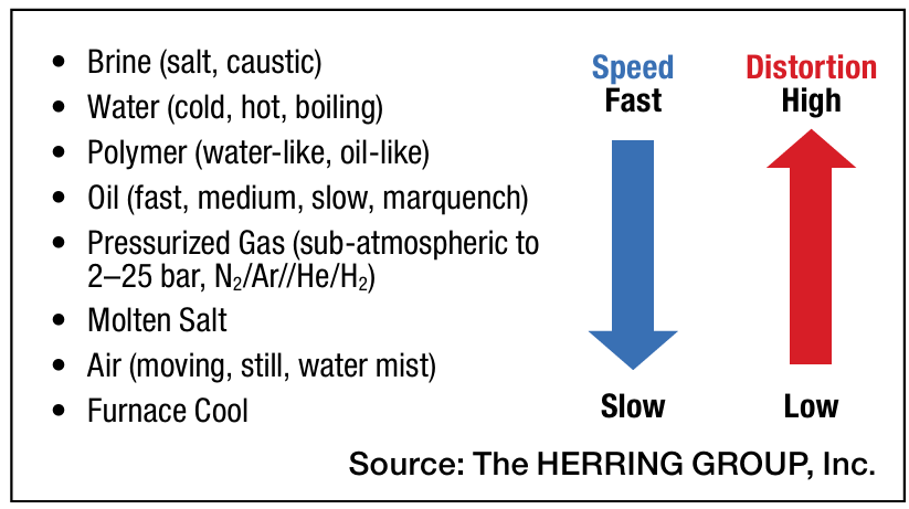


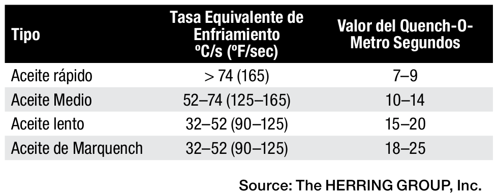


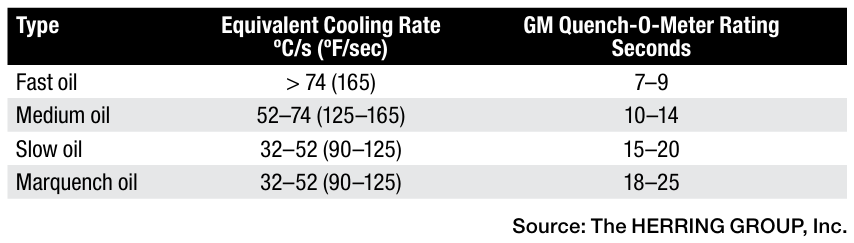
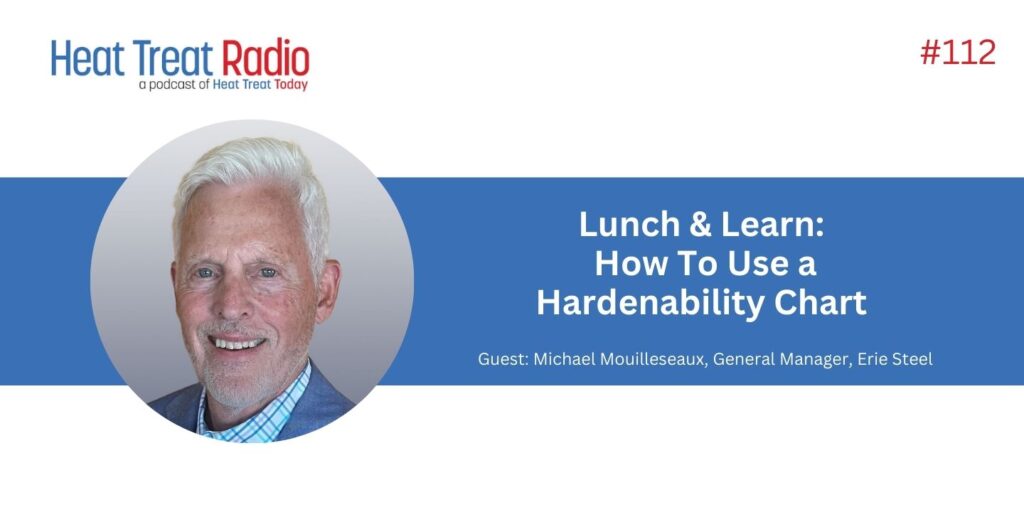


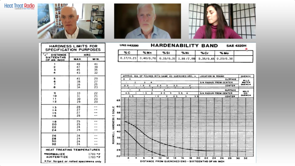
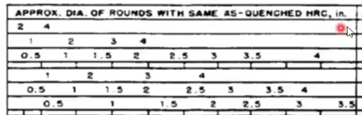
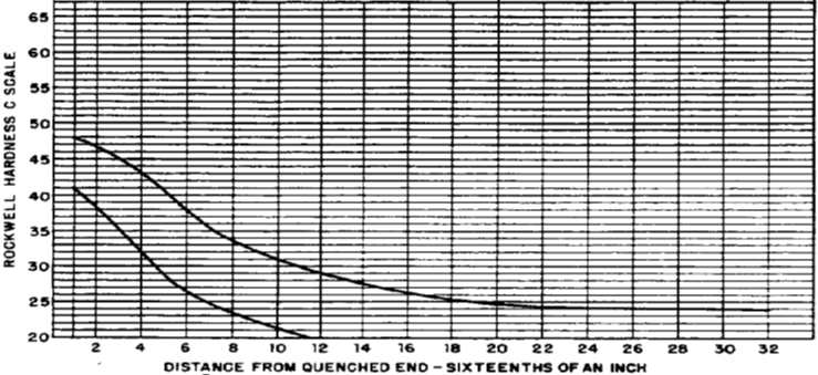


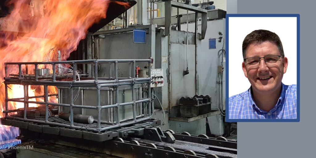
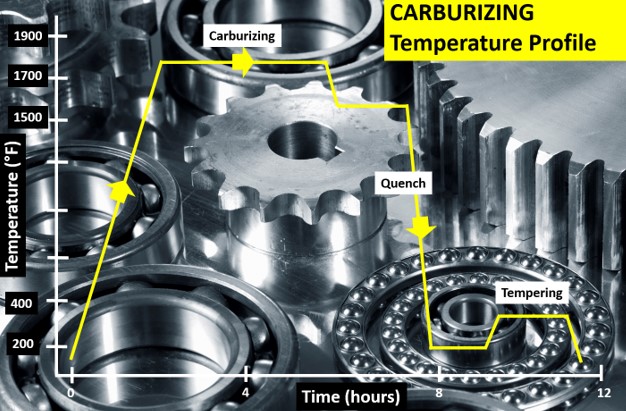

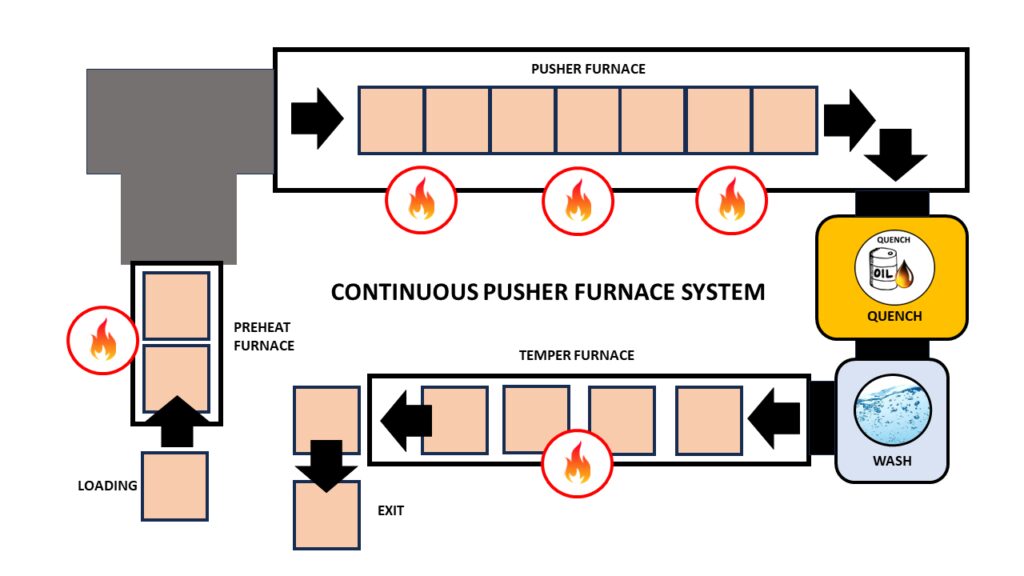

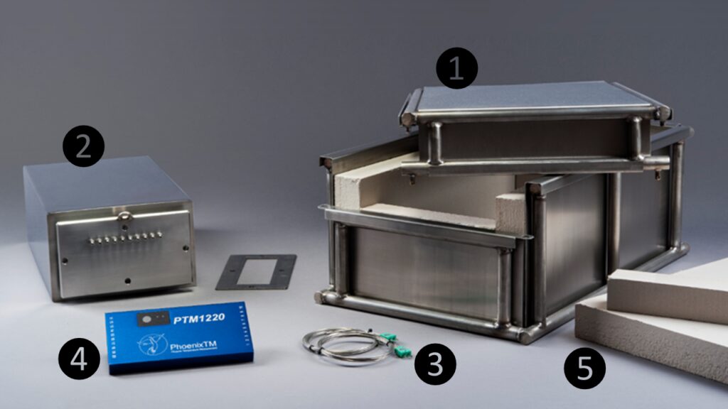

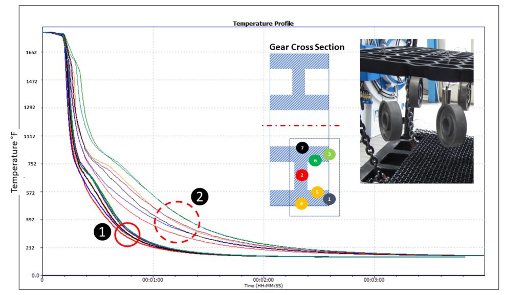

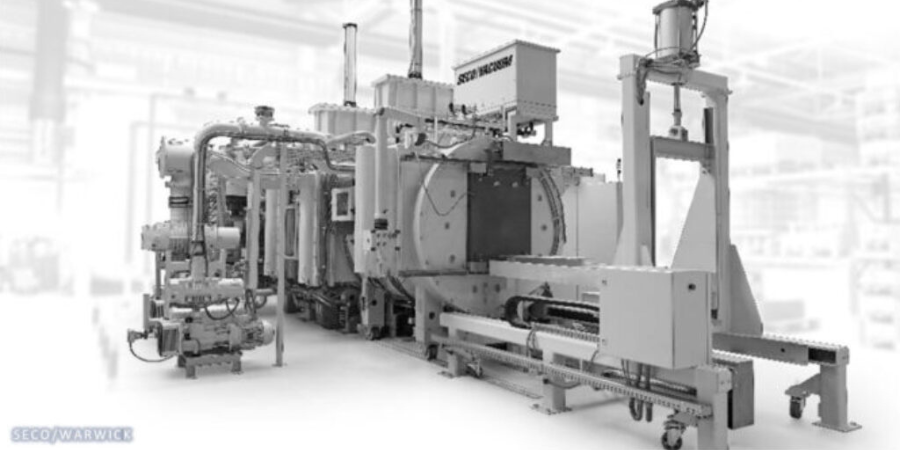


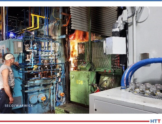
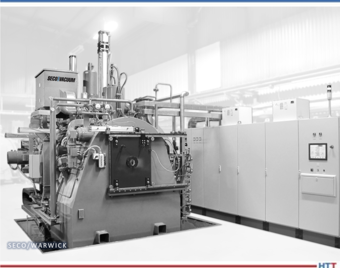
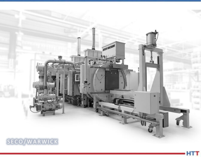
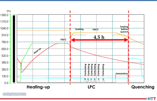

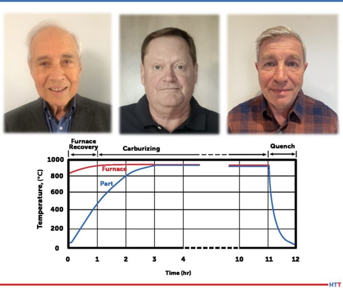


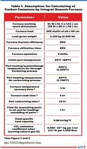
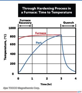
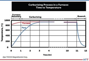


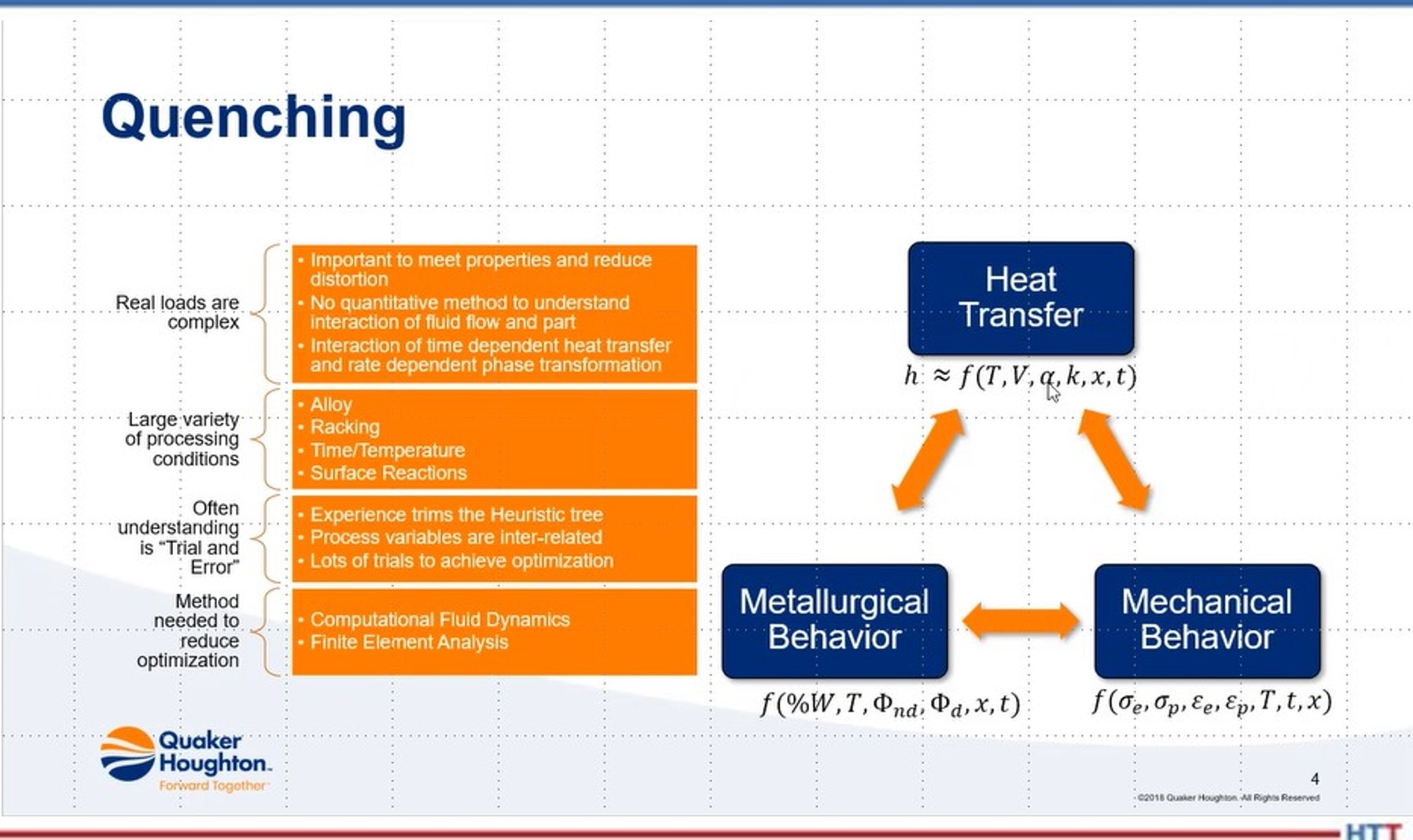 DG: Our next topic I want to talk about with you is simulation and modeling. We’ve talked a bit about that offline, and the developments there. As far as quenching goes, what can you tell us in the quenching world, as far as simulation and modeling? What is happening?
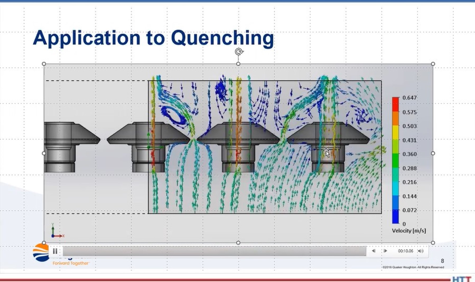 In terms of the simulation, it can be done if you’ve got good boundary conditions. The boundary conditions being the stuff on the outside of the part and the stuff inside the part. Once you do that, and you can do this with either using something like computational flow dynamics and then applying that as whatever velocity heat transfer coefficient that you get out of that and apply to the boundary of the part, then you can use a variety of different software programs, such as Dante or SIMHEAT — both of those are good, just a difference in their material databases. Each will give similar results but it’s a function — garbage in, garbage out. You have to have good material properties and good boundary conditions. If you have those, then you can get a reasonable result. But, if you don’t, you’ll just get garbage results.