Demonstrating Oil Quenching Effectiveness
 In this article by Lee Gearhart, Principal Engineer, Materials and Processes, Moog, Inc., and Chair, Aerospace Metals Engineering Committee, read about a “real time” heat treat inquiry regarding the interpretation of changed oil quenching effectiveness testing in AMS 2759, and Lee’s desire to ensure that the heat treater’s system maintains its effectiveness.
This article article first appeared in the latest edition (June 2020) of Heat Treat Today’s Automotive Heat Treat magazine.
* Please see the bottom of the article to view the AMS2759 sections to which Lee refers.
The Query:

A gentleman, to whom I’ll refer as Mr. XXXX, sent the following query to SAE, the publisher of Aerospace Materials Specifications. The subject line was as follows: “Clarification of AMS 2759G for Committee ‘E’.”
The letter read:
I would like to get some clarification about AMS 2759, Revision G, paragraphs 3.10.3 through 3.10.3.1.5.5. My issue, as an independent testing lab, is the terminology used in 3.10.3.1.5.1 and 3.10.3.1.5.3., and how
I am to determine the acceptance criteria for the hardness in the center diameter of the quench effectiveness samples supplied to us by heat treating companies. Let me walk through the steps that lead up to the determination of minimum hardness at the center of the diameter of the coupon prepared.
Paragraph 3.10.3.1.2 states specific size test bars to use for the quench effectiveness testing, based on the alloy, in sub-paragraphs a., b., c., and d. For 4130 (a.), use 1.5” long, 0.50” diameter bar and for 4330V (c.), use 7.5” long, 2.5” diameter bar. Then, we cut the test coupon from this specimen todetermine hardness at the center diameter, per 10.3.1.4.
Next, we have to determine whether this hardness result, taken at the center diameter, conforms to the spec, and here is where my issue is. Paragraphs 10.3.1.5.1 and 10.3.1.5.3 both state, “…shall not be less than the hardness on the end-quench hardenability curve corresponding to the diameter of the specimen…” So, if I am to use the diameter of the specimen as my guide from paragraph 3.10.3.1.2, a.and c., then the end-quench result on the mill cert corresponding to 8/16 would represent the 0.50”diameter, and 40/16 would represent the 2.5” diameter. ASTM A255 has you stop taking readings on the Jominy bar at 32/16 (2.0”), so there would not be a result on the Mill Cert for the 40/16 requirement.
I don’t believe this is the correct depth. I believe the end-quench result corresponding to one-half the diameter would be the appropriate depth to use as a minimum requirement, since we are taking the hardness reading at one-half the diameter; in the center of the diameter. So, the end-quench result on the mill cert corresponding to 4/16 would represent the 0.50” diameter and 20/16 would represent the 2.5” diameter bar. These requirements are more stringent and would better represent the effectiveness of the quench media to properly quench the specimens and correlate this back to the certified values of the material based on the mill cert reading for the corresponding J values.
Please review this and consult with the Committee to see if this would better represent the intent of these paragraphs for acceptance of quench effectiveness.
The Response:
Because of my position as chairperson of the Aerospace Metals Engineering Committee, the question eventually made its way to my desk. Here is my response:
When reading your question, it suddenly struck me – you’re missing the secret decoder ring! In other words, you cannot directly compare an oil quenched sample to a water quenched (Jominy) test coupon.
Allow me to give you a long-winded explanation that I wrote for Committee E on Steel for the Aerospace Materials Division, the committee that has jurisdiction of AMS2759 on Heat Treating of Steel. The committee had been asked for an explanation of what the 3.10.3 Quench System Monitoring is supposed to do; after the text in italics, I’ll directly answer you.
Let me start by noting the whole purpose of 3.10.3.1, which was to provide a means for a heat treater to demonstrate that their oil quenching system continues to work well. If they do the steps outlined in 3.10.3.1, they do not need to seek approval from their customers for this method. If they choose a different method for monitoring the quench system, they need approval by the cognizant engineering organization (CEO). Since a heat treat firm will probably have many customers with different CEO’s, it makes sense to have one test procedure on which all can agree.
The method starts with the heat treat quality function choosing one of the suggested alloys and bar size configurations noted in 3.10.3.1.2. The constraints of the choice are that the hardenability of the sample has to be enough that they will get full hardening in the center, but not so much that a bar 1.25 times the diameter chosen would get full hardening. (That prevents me from using an air hardening steel, which will not show any difference when my quench system degrades.) If the three choices in 3.10.3.1.2 (a-c) will not work, then (d) offers an out, using other materials and dimensions, established in pre-production testing.
Prior to initial production, and quarterly afterward, the heat treater runs one of the test bars in a typical or simulated production load. They then section out a half-inch slice from the middle of the length of the bar and test the hardness. If in the quarterly testing it remains above the acceptance criterion established by the pre-production testing, their quench system passes.

Accept/reject criteria is that the hardness in the center meets the hardness of the end-quench hardenability curve done by the original mill, or someone else, per ASTM A255, on the material used for the test. AMEC wanted this because using the generic curves in ASTM A304 is too general, and the curves are routinely done by the steel mills. I’ve attached an example cert (Figure 1) for some 4130 we bought not long ago, and at the bottom of the page are the Jominy numbers! They range from 51 to 24; so, which should I use?
To find the correct accept/reject hardness, I go to a curve that shows what Jominy distance in sixteenths of an inch reflects the cooling at the center of the size of test bar I use. If I’m using 4130 steel from my certified lot of material, the specimen is half inch in diameter, and the attached Timken curves say that the center of a half inch bar cooled with an H of 5 (good agitation) corresponds to a Jominy distance of 3/16, so the hardness required is 49 HRC. If I use a different curve, like the other one attached from an old Copperweld brochure (Figure 2), I get a Jominy distance of 31⁄2, so my acceptance number is somewhere between 49 and 46, so I’ll use 48 HRC. This difference is small, and unimportant, since I’m only using it to show if there is degradation in the oil quench performance.
This “compare it with the Jominy curve done by the mill” is only for the 4130 and 4330V specimens noted in 3.10.3.1.5.1 and 3.10.3.1.5.3. For specimens made of 4140, we call out HRC 44 in the center and HRC 50 in the 3⁄4 radius position of the 11⁄2 inch diameter specimen.
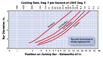
So, the 8/16 position on the Jominy curve doesn’t mean it’s appropriate for a half inch diameter specimen – it’s just pointing to the spot on the Jominy bar that’s 8/16 inch from the end that gets sprayed with water. The “secret decoder ring” I mentioned are the “Jominy cooling rates” or the “Pages from Timkin” attachment (Figures 3). These translate the speed of quenching at any sixteenth- inch position of a Jominy bar to the equivalent rate of quenching of surface, mid-radius, and center of bars of different size quenched in various coolants. I tend to use the “Jominy cooling rates” attachment, which I got from an old Copperweld Steel brochure, but since the Timkin Practical Data Handbook for Metallurgists is on the web for free, it’s probably a more universal reference.
Hence for 0.50” diameter 4130 bar, the center hardness should be that corresponding to between 3 and 4 sixteenths of an inch. For the 2.5” diameter bar, quenched in mildly agitated oil, the cooling rate at the center would be represented by the 14/16” position on the Jominy bar. Maybe 15/16” – it’s kind of hard to read. Hence you read the data from the mill cert FOR THE STEEL FROM WHICH THE PIECES WERE MADE and use those numbers as accept/reject. HTT
About the author: Lee Gearhart, P.E., has worked for Moog, Inc. since 1982 and is currently Principal Engineer, Materials and Process Engineering. In addition to being a worldwide resource for the company, Lee is the current chair of the Aerospace Metals Engineering Committee, where much of the discussion on heat treating specifications occurs.
For more information, contact Lee at lgearhart@moog.com or 716-687-4475
*Section 3.10.3 from AMS2759 Heat Treatment of Steel Parts (This section is one of the big changes to AMS2759 revision F, April 2018, which was then tweaked to revision G in August 2019)
The sections to which the article discusses is 3.10.3.1, 3.10.3.1.2 (a-d), 3.10.3.1.5.1 and 3.10.3.1.5.3
3.10.3 Quench System Monitoring
The quench system includes the quench volume, type of fluid, recirculation velocity and uniformity, and heat exchange capacity. The consistency of the quench system shall be monitored quarterly, by processing test parts, as outlined below, which are capable of detecting changes in the cooling characteristics of the system. Testing of water quench systems is not required. Quench system monitoring test procedures other than those described in 3.10.3.1 shall be approved by the cognizant engineering authority. When destructive mechanical property testing is required for part acceptance, quench system monitoring is not required.
3.10.3.1 Test Specimen Requirements
3.10.3.1.1 Test Specimen Alloy/Configuration
3.10.3.1.1.1 Round specimens of carbon or low alloy steel, of appropriate hardenability and dimensions shall be used. Selection of the specimen dimensions/hardenability combination shall be aimed at achieving full hardening (e.g., 95% martensite) at the center of the specimen. The specific combination of alloy/dimensions chosen shall be such that the specimen would not be capable of achieving full hardening at 1.25 times the diameter chosen for the test specimen. The length of the test specimen shall be at least three times the diameter.
3.10.3.1.1.2 The test specimens used for the initial and subsequent evaluation of a particular quenchant shall be from the same alloy and preferably the same chemistry heat of material to eliminate material chemistry and hardenability differences from the alloy selection. Hardenability results shall not be lower than that represented by requirements in 3.10.3.1.5.
3.10.3.1.2 Test specimen alloy/dimensions shall be one of the following:
- 4130 round bar, minimum 1.50 inches (3.81 cm) long, 0.50 inch (1.27 cm) nominal diameter.
- 4140 round bar, minimum 4.50 inches (11.43 cm) long, 1.50 inches (381 cm) nominal diameter.
- 4330V round bar, minimum 7.50 inches (19.05 cm) long, 2.5 inches (6.35 cm) nominal diameter.
- Other material and dimensional requirements established in pre-production testing or as specified by the cognizant engineering organization. See 8.5 for shape equivalent guidelines.
3.10.3.1.3 Test Specimen Processing
Quarterly quench system monitoring tests shall be run with a typical or simulated production load. Heat treat loads shall be processed in accordance with the appropriate AMS2759 slash specification requirements.
3.10.3.1.4 Specimen Testing Requirements
After quenching the test specimen, a 0.5-inch-thick specimen shall be cut from the center of the test specimen length and prepared for hardness testing in the untempered condition. Specimen shall be prepared to ensure it is free from overheating. The minimum hardness at the center of the diameter shall meet the hardness requirements of the approved procedure in 3.10.3.
3.10.3.1.5 Test Specimen Hardenability
3.10.3.1.5.1 Round Bar Specimen 4130
After quenching, the center of the diameter shall not be less than the hardness on the end-quench hardenability curve corresponding to the diameter of the specimen when tested in accordance with ASTM E18. The end-quench hardenability curve shall be the actual hardenability curve determined in accordance with ASTM A255 on the material used for the test specimen.
3.10.3.1.5.2 Round Bar Specimen 4140
The hardness in the center of the diameter shall not be less than HRC 44 and the 3/4 radius shall not be less than HRC 50 when tested in accordance with ASTM E18.
3.10.3.1.5.3 Round Bar Specimen 4330V
The hardness in the center of the diameter shall not be less than the hardness on the end-quench hardenability curve corresponding to the diameter of the specimen when tested in accordance with ASTM E18. The end-quench hardenability curve shall be the actual hardenability curve determined in accordance with ASTM A255 on the material used for the test specimen.
3.10.3.1.5.4 If other combinations are established, the accept/reject criteria shall be as specified in the ordering information.
3.10.3.1.5.5 It is the responsibility of the heat treater to provide the material and hardenability data specified above.
3.10.3.2 Any failures shall be documented by the heat treater’s corrective action system.
3.10.3.2.1 As a minimum, if the test specified in 3.10.3 fails, the quench medium shall be analyzed as specified in 3.10.3.3.
3.10.3.3 Quench Media Control
3.10.3.3.1 Each new shipment of quenchant from a vendor shall meet the requirements for the particular quenchant listed in 3.10.3.3.1.1 through 3.10.3.3.1.3 as applicable. The vendor shall furnish a certificate of conformance stating that the quenchant meets the requirements including, in addition to the vendor designation, the cooling curve, the cooling rate curve, the maximum cooling rate, and:
3.10.3.3.1.1 For mineral oil based quenchants, the certificate shall also include the viscosity, flash point, temperature at the maximum cooling rate.
3.10.3.3.1.2 For vegetable or ester-based oil quenchants, the certificate shall also include the viscosity, flash point, temperature at the maximum cooling rate.
3.10.3.3.1.3 For polymer quenchants, the certificate shall also include the undiluted pH and viscosity. The pH, viscosity, maximum cooling rate and the temperature at the maximum cooling rate shall be provided at 20% concentration by weight.
3.10.3.3.2 Cooling curve tests shall be performed semi-annually, or when required by corrective action (3.10.3.2), in accordance with ASTM D6200, ISO 9950 or JIS K 2242, ASTM D6482, or ASTM D6549, as applicable to the specific quench medium. If no alternative limits have been established by pre-production tests or specified by the cognizant engineering authority, exceeding the following limits compared to the initial shipment of quenchant shall be cause for corrective action:
- For mineral oils: Temperature of the Maximum Cooling Rate: (±68 °F) (37.8 °C) Maximum Cooling Rate: (±25 °F/s) (13.9 °C/s)
- For vegetable or ester-based oils: Maximum Cooling Rate: (±25 °F/s) (13.9 °C/s) Temperature of the Maximum Cooling Rate: (±68 °F) (37.8 °C)
- For polymer quenchants: Maximum Cooling Rate: ±15% Temperature of the Maximum Cooling Rate: ±15%
Demonstrating Oil Quenching Effectiveness Read More »


 From top left clockwise