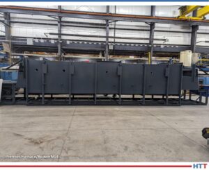
The first of five new mesh belt temper furnaces was shipped from Michigan manufacturer to the southern U.S. The second and third furnaces are ready for the next phases of production, and they all will be used for preheating and tempering of steel bar stock.
Premier Furnace Specialists, Inc./BeaverMatic has scheduled the first installation for the last week of August. The remaining four will be completed and installed through January 2024. These furnaces are natural gas fired with an operating temperature of 1600°F. They have thirty-six inch wide mesh belts capable of 2000 lbs per hour. The furnaces are all operated through a 23.8” HMI color touch screen interface.
Mesh belt furnace from Premier Furnace Specialists, Inc./BeaverMatic Source: Premier Furnace/BeaverMatic
“We built them a similar furnace in 2022,” commented Steve Ignash, sales engineer at Premier. “The [latest] system was designed, built, and tested at our new 40,000 square foot facility in Farmington Hills, MI.”
Find heat treating products and services when you search on Heat Treat Buyers Guide.com
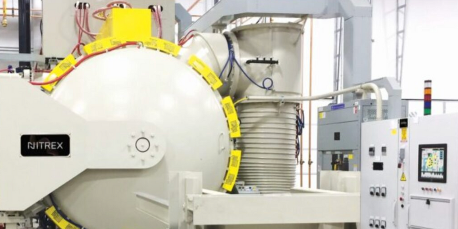
A set of nitriding/nitrocarburizing systems has been installed for a European hydraulics manufacturer. The furnaces help produce components for hydraulic pumps and motors and strengthen the company’s in-house heat treatment capabilities.
The furnaces are from Nitrex – a company based in North America with international locations. This is the second set of systems from the same manufacturer. These systems primarily serve to nitride/nitrocarburize pieces made from various steels and alloys and will help meet the growing demand for hydraulic components.
Hydraulics systems expand heat treat capabilities Source: Nitrex
“The nitriding/nitrocarburizing furnaces have [. . . integrated] seamlessly into our customer’s operations,” commented Mark Hemsath, vice president of sales, furnaces & heat treating services at Nitrex.
Find heat treating products and services when you search on Heat Treat Buyers Guide.com
Discover expert tips, tricks, and resources for sustainable heat treating methods Heat TreatToday’srecent series. Part 4, today’s tips, covers induction heating, quench, and insulation tips. We’ve added resources towards the end of today’s post for further enrichment.
This Technical Tuesday article is compiled from tips in Heat TreatToday’sMay Focus on Sustainable Heat Treat Technologiesprint edition. If you have any tips of your own about induction and sustainability, our editors would be interested in sharing them online at www.heattreattoday.com. Email Bethany Leone at bethany@heattreattoday.com with your own ideas!
1. Tips for Induction Hardening
Contact us with your Reader Feedback!
What are the benefits of induction hardening? Here are a few:
Saves space: Induction hardening requires minimum space required in comparison with furnaces
Saves energy: Induction heating equipment does not need to be kept running when not in use
Clean: Induction heating equipment requires no combustion gases
Energy-efficient: Only a small proportion of the material needs to be heated
Minimize deformation: Induction hardening requires no applied force
Save maintenance costs: Inductor coils have a long life, reducing the need for maintenance
Source: Humberto Torres Sánchez, Chief Metallurgist, ZF Group
2. Insulation = Key for Energy Savings in Vacuum Furnaces
Look for insulation quality in your next vacuum furnace.
Source: NITREX
Improvements in insulation materials are also contributing to greater energy efficiency of vacuum furnaces. Most furnaces on the market today have a 1” (25.4 mm) graphite board with bonded Grafoil and two layers of graphite felt. However, the insulation performance of a 1” (25.4 mm) graphite board is about 25% less efficient than a 1” (25.4 mm) graphite felt. For processes that require high operating temperatures, typically over 2,200°F (1,204°C), an all graphite felt that is 2” or 2.5” thick (50.8 mm or 63.5 mm) minimizes heat loss inside the hot zone. Efficiency gains of up to 25% are possible over the standard 1” (25.4 mm) board and 1” (25.4 mm) graphite felt insulation and an even greater gains at higher operating temperatures. To safeguard the graphite felt from mechanical harm and localized compression, these thicker all-graphite felt insulation configurations are usually covered with a carbon fiber composite (CFC) sheet about 0.050” (1.27 mm) thick.
Fuel efficiency (and the stringent requirement for passenger safety) has raised the bar for the automotive industry to procure steel with high strength, hardness, and ability to fabricate. Reduction of weight requires lighter cars with thinner body material which can absorb impact. These dual contradictory properties of high hardness material which can be easily shaped can normally be achieved either by heat treat or through addition of alloys. These two processes are described below.
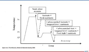
Normal heat treatment to produce small grains in the material will increase the hardness in steel but also create a propensity to fracture. Thus, a process known as quench and partition — where carbon diffusion from martensite to retained austenite to stabilize the latter — has been introduced. Further verification and prediction of the phases has been conducted using thermodynamics modeling for phase characteristics by Behera & Olsen at Northwestern University, Materials Science and Engineering.
The process starts with full automatization (or in some cases intercritical annealing) followed by fast quench to a defined quench temperature (QT) between the martensite start, Ms, and martensite finish, Mf, temperature. The steel is then reheated to the partition temperature (PT) and held there for a certain partition time followed by a quenching step again to room temperature, as shown in the image.
Quench and partition process
Source: Speer et al. The Minerals, Metals, & Materials Society 2003
The quenching step establishes the largely martensite matrix while the partition step helps stabilize the retained austenite by carbon partitioning. During the holding step, carbon diffuses from martensite to retained austenite and thus improves its stability against subsequent cooling or mechanical deformation. The final microstructure consists predominantly of tempered martensite and stabilized retained austenite with possibly a small amount of bainite formation and carbide precipitation during the partition step and fresh martensite formation during final quenching.
The other process to achieve high hardness and high ductility is by alloy addition in carbon steel. Over, 2,000 different types of steel exist. A new type of steel that is extremely strong, but simultaneously ductile is used in the automotive industry. Small quantities of elements like vanadium or chrome in steel promotes ductility. They are not brittle; however, up until now they have not been strong enough to enable the construction of car bodies with thinner sheets.
In the crystals of steels, the atoms are more or less regularly arranged. Steels become particularly ductile though if they can switch from one structure to another. This is because this process allows energy absorption, which can then no longer initiate any damage in the material. In a car body or other steel components, tiny areas then alternate with the two different atom arrangements.
Ductile steels have two coexisting crystal structures. The search produced an alloy made from 50% iron, 30% manganese and 10% respectively of cobalt and chrome (Max Planck Institutes).
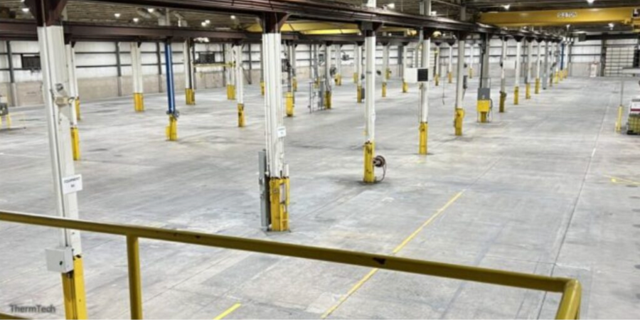
A heat treat company based in Waukesha, WI, has expanded with a 95,000 square foot building in New Berlin, WI. The New Berlin facility is seven miles from their Travis Road campus.
Steve Wiberg and Mary Wiberg Springer, owners of ThermTech, share that the plant’s square footage will be 270,000. The new space will be used for the company’s expansion. The new facility will allow the heat treater to continue to meet their clients’ needs as they expand their core offerings: hardening, tempering, surface heat treatment, carburizing, vacuum treatments, annealing, press quenching, austempering, and aluminum heat treatment.
Find heat treating products and services when you search on Heat Treat Buyers Guide.com
What makes the geometry of a part “complex”? With the increasing use of AM and 3D printing for parts along with typically complex parts, heat treaters in many industries must acquire the equipment and technical know-how for precise applications.
This Technical Tuesday article is compiled from Heat TreatTodayarticles and industry news releases. Email Bethany Leone at bethany@heattreattoday.com or click the Reader Feedback button below to chime in on the topic.
What Are Complex Geometries?
Contact us with your Reader Feedback!
Complex geometries in industrial parts are often defined by their intricate patterns and structures, which entail specialized heat treat processing. As Inductoheat describes in a case study with Stellantis, “Many times, complex geometries of components are linked to intricate hardness patterns and specific requirements for magnitude and distribution of residual stresses.”
Heat Treat Equipment for Processing Parts with Complex Geometries
Be it for highly customized medical implants or for engine components in the burgeoning electric vehicle industry, complex geometries need to heat treated carefully. Fasteners in the medical device industry can be quite intricate and susceptible to creep or other dimensional changes; one method heat treating these parts — particularly titanium alloy parts — would be in a vacuum furnace. In vacuum and in hot isostatic presses, the environment allows for complex geometries that are 3D printed to be made into a unified whole piece. “Heat conduction can be carefully monitored [in induction heating coils] to confirm that an overheat condition does not occur at the target temper areas,” making induction a key candidate for heat treating your parts with complex geometries (“Tempering: 4 Perspectives — Which makes sense for you?“). To accommodate the complexities of certain parts, designing an induction coil for the desired case hardening may entail simulation to “[predict] coil heating, which altogether results in a longer coil lifetime,” (“Simulation Software and 3D Printers Improve Copper Coils”). For more on induction coils, check out this article by Dr. Valery Rudnev.
Suffice it to say, there is a great diversity of heat treatment options to explore when it comes to identifying the appropriate equipment for your application.
What Processes Are Used in Heat Treating Complex Geometries?
Perhaps you have all of your equipment needs necessary for heat treating your parts with complex geometries. Are you completing your heat treat processing in the most technically sound manner? Check out the following excerpts that speak to processing complex geometries.
“[Forging] at elevated temperatures enables reaching high strains and forming complex geometries in a single stroke. Additionally, thermal and mechanical influence during the forging can lead to improving local mechanical properties and the quality of the resulting joining zone.” (“Thermomechanical Processing for Creating Bi-Metal Bearing Bushings“)
“In some cases, such attempts result in a component’s geometries that might be prone to cracking during heat treating or might be associated with excessive distortion . . . . The subject of induction hardening of complex geometry parts (including but not limited to gears, gear-like and shaft-like parts, raceways, camshafts, and other critical components) is also thoroughly discussed, describing inventions and innovations that have occurred in the last three to five years.” (“Heat Treat Training Benefits Stellantis“)
“LPC [low pressure carburizing] with gas quenching can be an attractive option for distortion prone complex geometries as the cooling rates are slower than oil quenching; however, given the slower cooling rate, it becomes very important to choose a higher alloyed steel that will achieve the desired hardness.” (“Elevate Your Knowledge: 5 Need-to-Know Case Hardening Processes“)
Complex Geometries In the News
See how your peers are solving complex geometries needs in these real-life partnerships with industry suppliers. From additive manufacturing (AM) and precision manufacturing parts to heat treat technology, maybe your company is next to leverage manufacturing equipment to “wow” the industry.
Heat Treat Today is partnering with two international publications: heat processing, a Vulkan-Verlag GmbH publication that serves mostly the European and Asian heat treat markets, and Furnaces International, a Quartz Business Media publication that primarily serves the English-speaking globe. Through these partnerships, we are sharing the latest news, tech tips, and cutting-edge articles that will serve our audience — manufacturers with in-house heat treat.
In this article, we look at annealing equipment, innovation in waste management, and thermal processes in Li-ion batteries.
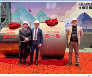
Investing in production of high-performance electrical steel in Shanghai
Source: Baowa
New Electrical Steel Lines for EV Motors
“Fives, a leading engineering group with broad expertise in steel processing and technology, has designed and delivered thermal sections for a new annealing and pickling line (APL) and two new annealing and coating lines (ACL). The lines, designed to produce high quality non-grain oriented (NGO) grades for electric vehicle motors, delivered their first coil between December 2022 and February 2023.”
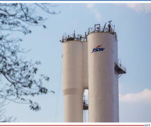
Addressing the issue of plastic waste mgmt.
Source: worldsteel
Successful Trials Will Help Manufacturer Reduce Carbon Footprint
“Integrated steel manufacturer JSW Steel has accomplished a ‘significant breakthrough in environmental sustainability’ by successfully injecting waste plastic into Blast Furnace 3 at its Vijayanagar steel plant following extensive trials.”
Left to right: Huang Ligang, general manager, Kilnpartner; Zhang Yuejin,
Chairman of the board, Kilnpartner; Michael Reisner, CEO, Aichelin Ges.m.b.H.;
Christian Grosspointner, CEO, Aichelin Holding; and Fan Xiaochun, CEO,
Kilnpartner, after signing the contract.
Source: Aichelin
AICHELIN Cooperation Agreement
“The thermal processes used to treat the essential components of Li-ion batteries represent a key technology in this process. These include the cathode as LFP (lithium iron phosphate) or NMC (nickel manganese cobalt) and the active anode material. Only through a highly accurate heat treatment can the crystal structure and morphology of the material be trimmed to ‘peak performance.’ In order to achieve this goal, each manufacturer has its own processes. The common basic requirement is flexible and reliable plant technology, the so-called ‘kilns.’”
Discover expert tips, tricks, and resources for sustainable heat treating methods Heat Treat Today’s recent series. Part 3, today’s tips, covers some combustion content. We’ve added further resources towards the end of today’s post to further enrich your combustion knowledge.
This Technical Tuesday article is compiled from tips in Heat Treat Today’sMay Focus on Sustainable Heat Treat Technologies print edition. If you have any tips of your own about combustion, our editors would be interested in sharing them online at www.heattreattoday.com. Email Bethany Leone at bethany@heattreattoday.com with your own ideas!
1. Combustion Efficiency: Do You THINK or Do You KNOW?
Minimize emission with data Source: PSNERGY
Contact us with your Reader Feedback!
Installing retrofittable monitoring equipment provides real time and historical combustion data.
Combustion is a chemical reaction. With the right mix of fuel and air, emissions are minimized while heat output is maximized.
The question is: “Do you think it is right or do you know it is right?” With today’s technology, knowing combustion is running efficiently by maintaining proper ratios at each burner is not only possible, it is necessary.
Minimize emissions, improve quality, and maximize heat output per BTU with data!
Source: Taylor Smith, Specialist of Technical Sales and Marketing, PSNERGY
#combustion #emissions #energy #efficiency
2. NOx and High Efficiency Burners
Nitrogen oxides, or NOx emissions, are generated in high temperature combustion systems. Nitrogen and oxygen are present in combustion air and react in the high-temperature region of the flame to produce various oxides of nitrogen. NOx is a generic term combining NO (nitric oxide) and NO2 (nitrogen dioxide).
Modern high-efficiency burners with a high pre-heat of combustion air through known means of recuperative or regenerative systems increase the temperature of the oxygen and nitrogen within the combustion air and the potential for high NOx levels. Therefore, NOx reduction methods become even more important with high pre-heat burners.
Typical reduction methods of NOx in high efficiency burner systems include:
Recirculation of combustion products or flue gases is very effective to reduce temperature peaks and therefore reduce nitric oxide formation.
Lowering the temperature of the flame by air staging at the point of combustion.
Flameless oxidation (Flox) reduces NOx using the previously mentioned principles by lowering the peak flame temperature. Flameless oxidation works by injecting gas and preheated air directly into the system, and above the autoignition temperature.
Oxygen combustion can theoretically reduce NOx formation by taking away nitrogen in the combustion process. In this case, pure oxygen is introduced instead of combustion air, but this application is typically limited by process and costs associated in producing pure oxygen.
3. Burner Tuning & Calibration — It’s Not Your BBQ Grill!
Burner tuning and calibration Source: WS Thermal
Burner adjustment to nominal gas and air ratios is a typical component of your combustion equipment maintenance. However, this process cannot be minimized in importance as any adjustment can affect operation, efficiency, exhaust emissions, and equipment life. Factors to consider and address during any burner adjustment include:
Burner adjustment should always be done (when possible) at normal furnace operating temperature under typical production to maintain best conditions for final calibration
Provide clean combustion air: maintain blower filter and consider source of any plant air
An increase of gas may not increase power to system due to heat transfer or throughput issues
A decrease in combustion air will not create a hotter flame or add power to the system as this may only create a gas-rich operation resulting in reduced power and CO in exhaust
Verify gas and combustion supply pressures and consider creating a monthly log of incoming pressures
While a visual inspection of flame can help to verify operation or proper combustion, burner gas/air adjustment cannot accurately be performed by simply looking at color or size of flame
A working understanding of the burner system is important to determine and verify values to gas/air and excess O2 to specific application
Work-from-home benefits and challenges extend to work-from-travel occasions! Access corporate networks and systems with 8 cybersecurity best practices.
Today’s read is a feature written by Joe Coleman, cybersecurity officer at Bluestreak Consulting™. This column is in Heat Treat Today’sJune 2023 Heat Treat Buyers Guide print edition.
Introduction
In this eighth Cybersecurity Desk installment, understand the benefits and challenges associated with working from home or accessing corporate networks and systems while traveling.
Why Are So Many People Working from Home?
The COVID pandemic forced many companies to adapt to remote working and work-from-home (WFH)
Joe Coleman Cybersecurity Officer Bluestreak Consulting Source: Bluestreak Consulting
policies. Even though these policies have provided employees with more flexibility, they have also highlighted cyber risks that companies must consider. As of March 2022, work-from-home and working remotely have increased by 238% compared to pre-pandemic numbers. Although that number has reduced somewhat recently, it has changed the way companies operate and view WFH.
Several benefits of WFH include:
Increased employee retention and productivity
Reduced distractions and interruptions by coworkers
Reduced company overhead costs
Increased family time by eliminating commute
One of the first challenges most companies face when shifting to a WFH model is ensuring every employee has high-speed internet access. Most employees will use home Wi-Fi network or cell phone/wireless carrier as an internet “hot spot.” The first common sense rule of thumb is always try to avoid public Wi-Fi and public charging stations. Any way you choose to access high-speed internet, it must be secure. By now, most companies should have WFH or remote work policies and procedures in place, with employee awareness and training, because they MUST be followed to reduce cybersecurity risks.
Cybersecurity Best-Practices for Securing Remote Workers
If your company has employees that work from home and you’re wondering what cybersecurity measures you should put in place, here are some best practices to help you:
Secure your work sessions: Using a single room that has a door that can lock is the ideal situation when possible. Many WFH employees are either sitting at their kitchen table or in the living room. In those cases, make sure to have your monitor facing a wall to prevent family or guests from viewing your work session and lock your computer when you’re away.
Separate your home and business networks: Separate your Wi-Fi network so company-approved devices will be separate. Even better, use a secure network and a company-issued Virtual Private Network (VPN) to access your business accounts. You can also use BeyondTrust for secure remote access. Home routers should always be updated to the current software version when it becomes available.
Separate work and personal devices: When accessing your corporate network, only use company-approved devices. Unless your company allows Bring-Your-Own-Device (BYOD), never use an unapproved device to access your company network.
Think before you click: Hackers use phishing and other social engineering methods to target employees with legitimate-looking emails and social media messages. These can trick users into providing confidential data, such as usernames, passwords, credit card numbers, social security numbers, account numbers, etc. SLOW DOWN.
Don’t click on links sent from an unknown or untrusted source. Resist the urge to click links in a suspicious email. You can hold your cursor over a link, and it will show you (in the bottom left corner of your screen) the website that it will go to if you click on it. If it’s an unknown or suspicious site, DO NOT click on it.
Click the Image TO Download More Than 350 Cybersecurity AcronymsAntivirus with real-time scanning: Antivirus software detects the presence of malware on your computer. A dynamic scanning feature repeatedly checks for computer infiltration by a malicious threat. Always keep your antivirus up to date and active.
Update programs, applications, and operating systems: Vulnerabilities in applications and operating systems are continually being found and exploited. Cybercriminals often use these vulnerabilities to exploit data and infiltrate devices and networks. Application vulnerabilities are a cybersecurity challenge of remote working. Make sure you are regularly performing updates as they are released.
Use 2-Factor Authentication (2FA) or Multi-Factor Authentication (MFA): If you’re not using 2FA or MFA, you are NOT secure. You should use 2FA or MFA wherever it’s available. Your company should have this requirement in its policies and procedures.
Use strong PINs/passwords on your devices: Strong passwords should contain a good mixture of upper/ lowercase letters, numbers, and symbols (or special characters). Passwords should also not be based on dictionary words and should contain at least twelve characters (the longer the better). Never use the same password for multiple accounts and use a password generator and a password manager.
About the Author:
Joe Coleman is the cybersecurity officer at Bluestreak Consulting™, which is a division of Bluestreak | Bright AM™. Joe has over 35 years of diverse manufacturing and engineering experience. His background includes extensive training in cybersecurity, a career as a machinist, machining manager, and an early additive manufacturing (AM) pioneer. Contact Joe at joe.coleman@go-throughput.com.
Find heat treating products and services when you search on Heat Treat Buyers Guide.com
Heat Treatments, a heat treatment services provider, has added a nitrocarburizing system from a North American based company. The system supports the heat treater’s nitrocarburizing efforts, which include a variety of materials and applications, such as alloy steels, tool steels, and high-speed steels for aluminum extrusion dies.
The NXK series sees the furnace and control panel mounted on an integral platform. The particular NXK-812 model is designed to treat workloads weighing up to 2645 lbs., with measurements of 31.5″ x 47.25″. The system is equipped with process technologies such as Nitreg®-C controlled nitrocarburizing and ONC® post-oxidation.
“We are proud to continue our partnership with Heat Treatments . . . in New Zealand,” said Nikola Dzepina, account executive, Nitrex. “[P]rior installations [have been] in operation between 20-30 years.”
The system was commissioned in the first quarter of 2023.
Find heat treating products and services when you search on Heat Treat Buyers Guide.com
You’ve built your vacuum furnace maintenance program, but still looking for maintenance tips for common issues?
Don Marteeny and Caleb Johnson at SECO/VACUUM Technologies lay out their expert advice to assess your vacuum furnace maintenance issues from all angles. Thanks to Doug Glenn, publisher ofHeat TreatToday, for hosting this interview.
Below, you can watch the video, listen to the podcast by clicking on the audio play button, or read an edited transcript.
The following transcript has been edited for your reading enjoyment.
Doug Glenn: With us today is Don Marteeny. Don is from SECO/VACUUM Technologies LLC and is the VP of engineering. Don has a lot of experience in this industry, so his input will be valuable.
Don Marteeny
VP of engineering
SECO/VACUUM Technologies
Also with us is Caleb Johnson who is the field service manager, also for SECO/VACUUM Technologies. Gentlemen, we appreciate you joining us.
We’re just going to jump right in. We’re talking about top vacuum furnace maintenance concerns.
Trouble Reaching Vacuum Levels (01:35)
Doug Glenn: Probably the most dire concerns is: “Dang it, I can’t get this doggone vacuum furnace down to the vacuum levels that I want.” Where do we go? What do we do?
Caleb Johnson: Yes, that is probably one of the more critical problems on a vacuum furnace. There are a lot of issues that would stem from that.
Caleb Johnson
Field Service Manager
SECO/VACUUM Technologies
Source: LinkedIn
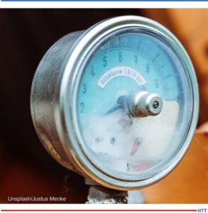
One of the first checks I would ask to look at is the vacuum gauge itself. Does the trending look okay? Do we think the gauge is still functioning properly? What does your scaling look like? Since those are electronic items, they do have a life on them. It’s an easy one to rule out, right off the bat.
The next place to check would be your vacuum pumps. Are they functioning okay? Has the oil been changed recently? Is the pump still working well? Just going through some of the basic checks like this can tell us how the furnace is doing.
Doug Glenn: Is it typical that the vacuum gauge will fail slowly over time? Does it start to get off target? Maybe it immediate: “Boom. This thing is just gone.”
Caleb Johnson: I think it can be either way. On the one hand, it could just not read. On our furnaces, they usually fail high. It will just say it’s at atmosphere even though you’re under vacuum. On the other hand, the low level on the vacuum gauge won’t reach as good a vacuum. Maybe the furnace is there, but the gauge doesn’t register that. The gauge itself just starts drifting. So, yes, either way — they are both common.
Check the gauge
Source: Unsplash/Justus Menke
Doug Glenn: Alright. So, the gauge first and then the pump. Was there anything else?
Caleb Johnson: For the pump, I think you could look at the amp draw on it and make sure the motor is still functioning properly — that’s a big one.
Doug Glenn: Yes, good.
Don Marteeny: Another thing that I’ve seen commonly is that a customer is running a process that may, in some way, present some contamination to the furnace. Usually, one of the questions that I ask after that process is, “How long has it been since you have done a cleaning cycle?” By that I mean, having the furnace run a hundred degrees over the process temperature for 8 hours just to basically bake everything out of the insulation.
A further question to ask: Was the furnace open over the weekend? Did somebody accidentally leave it open, didn’t pump it back down, and there’s moisture.
I would expect the first run that there would be problems reaching vacuum. There’s an easy answer to that. Yes, you might not get through the production that day, but you’ve got to put it through a cleaning cycle first. Let it run over night then start back in the morning and see where you are.
Furthermore, this can also apply to the gauge. Sometimes it’s not necessarily that the gauge has failed, but there is some contamination. There are ways to prevent that, like the installation of what we call “a clarifier” — basically a copper tube that allows anything that might be in the environment to condense before it reaches the vacuum gauge.
There are several remedies for these common issues, and we have to go through the list of all of them when this comes up.
Caleb Johnson: I would say, too, that cleaning cycle gives us a baseline because all our vacuum leak checks are specified in a clean, dry, empty furnace. After a burnout, you try to get rid of all that contamination. When the door hasn’t been opened yet, that’s the best time to do a leak-up check and say, “Is any air getting into the furnace?”
A lot of times, you’ll see discoloration on your load or the furnace itself — if you’re getting air or moisture in there — some blue or green colors that allude to that. Now, if the load is off-gassing, maybe that’s a common color that you’re getting, but specifically, if you’re getting air in the furnace, you may see the discoloration. The leak check would show that.
A lot of times we’re specified at 10 microns an hour, and, over time, furnaces might not meet that spec. As you get further and further from that spec, then it’s time to come back and do a helium leak check. Sometimes they’re called “using the mass spectrometer” — we call it a leak detector — but that’s a surefire way to find out exactly where any air might be getting in the furnace.
Doug Glenn: That was my next question on this, before we get off the topic of not being able to reach the vacuum level: Let’s say it’s not the gauge, let’s say it’s not the pump. What are the common areas? The one that jumps to my mind: Did you check the door seal? Is that valid? Are there other places that we can be checking right off if we’re failing the leak-up test? What are the most common places where we’re going to see failure to hit the vacuum levels?
Caleb Johnson: Door seals, obviously, are the number one issue because that’s constantly opened and closed. They might dry out. The seal needs to be constantly cleaned and greased. Dirt could fall in there. That’s definitely one. Also, the furnace is going through heating cycles, so the power feedthroughs, they’ll get hot. As they expand with the heat and contract with the cold, it creates a potential for a leak because those seals are constantly shifting a little bit.
Really, any penetration that goes from outside the furnace into it is a potential for a leak. Looking at what’s going to see the heat; what’s going to move a little bit; and like the door seal — what’s been opened or even if maintenance was done and some valve was replaced or a seal was touched — that’s usually the first thing to go for.
Doug Glenn: That was the other common sense point worth mentioning: If something was replaced in the furnace, especially anything that penetrates the shell, and you weren’t having troubles before that, obviously you want to go check that stuff out.
Don Marteeny: More to that point, we’ve come across a couple times where a valve was replaced, and that valve was, say, on the incoming gas line, maybe nitrogen or argon. All of a sudden, we have a leak, but we can’t find it. We’ve leak checked the entire furnace multiple times and still can’t find a leak.
Well, the next place to look — and it seems illogical — but the next place to look is that valve because that did change. Maybe there’s no outward appearance of any oxidation, but low and behold, there is some nitrogen or argon leaking into the furnace through a valve seep that we didn’t expect. It doesn’t happen all the time, but it does happen. That one is especially frustrating to find because it’s the last place you’ll ever look.
Waterflow alarm (08:49)
Doug Glenn: Let’s say you’ve got a waterflow alarm. What’s the first thing we are looking for?
Don Marteeny: I’ll jump in on that one, Doug. It’s not just a cold-wall furnace because certainly there are atmosphere-style furnaces out there that have water-cooled flanges that do require some water cooling. Many of those passages that feed those flanges or, like we talked about, power feedthroughs are very small.
All of a sudden you look down and say, “Oh, there’s an alarm on one of the power feedthroughs that’s not getting enough water; the temperature is too hot.” Okay, chances are good that there could have been some contamination that was somewhere in the system that is now blocking one of those small holes — and I’m talking a half inch or a quarter inch hole — and we just don’t have the flow that’s expected.
The natural first step is: How long has it been since you’ve cleaned the system? How long has it been since the system has been flushed? Again, it’s going to be something that you don’t typically think of, don’t do that often, but if, for some reason, there has been some exposure to air in the system (and exposure to air will develop and typically promote the growth of bacteria which can cause issues in the system) or just from natural deterioration.
A lot of those systems are steel pipe, and they develop some scale. That scale goes somewhere, and the first place you’ll see it is on the small passages because it blocks the passage.
There are a couple biodegradable descalers, at least, that I’m aware of, available on the market. If you’ve got glycol, that glycol can be pumped out of the system, screened, filtered, and put back in. At the same time, you can purchase a descaler which typically can be mixed with city water, and you basically flush the system. After maybe one or two flushes, you can be fairly confident that you’ve removed a lot of that scale and reintroduced the glycol if you need to or reintroduced the water coolant.
The important thing is that you’ve replaced the rust inhibitor or any other chemical treatments that you think are necessary or you’ve been told are necessary by the equipment manufacturer.
Doug Glenn: On this water-cooling system, what percentage of vacuum furnaces out there have closed-loop cooling systems, as opposed to somebody just running city water through a furnace for cooling?
Caleb Johnson: I think the majority of our customers do have closed-loop, but it also depends on how much equipment they’re cooling. If it’s a single furnace, the best scenario is usually just a closed-loop, small system. But when you have multiple furnaces in a room, then you’re on a much larger system. It takes more cooling power, and it may not be city water they’re running through. It might be an open-looped system or just multifaceted with their stations.
Doug Glenn: It’s been quite a while, and I don’t know if it still happens that you’ve got somebody that’s running a cold-wall vacuum furnace and they’re running city water through it. Soon all you’ve got is just a bunch of sludge and stuff, and you’re not a cold-wall anymore — you’re basically just heating sludge.
Don Marteeny: Yes. City water can be especially challenging, unlike having a glycol mixture with DI water (deionized water) or DI water that you input into the system initially. That city water can be hard, so it has a lot of dissolved solids. It can have organics that can end up causing issues if there’s a certain section of the vessel that doesn’t get the right circulation. All of a sudden you get a settlement of those sediments in the water. There are lots of different challenges that are brought on by using city water.
Caleb Johnson: And heat is an activator, as well, right? So, as it’s trying to pull that heat off, now that’s activating some of the stuff — that’s what causes some of the scale buildup or the bacteria. Making sure that the size of the system is adequate is necessary, as well.
Doug Glenn: On modern-day vacuum furnaces, do they have regular flow monitoring of water? Do you know if water is going through and can you tell, over time, “Hey, my flow is slowing down” — can you see it coming?
[blocktext align="right"]I would recommend if you do a routine check-out of the furnace for maintenance, maybe in the summertime, that’s the time to do it. Flushing the furnace, removing the coolant, etc., is quite an undertaking.[/blocktext]Caleb Johnson: In our furnaces, we use digital indicators. Some furnaces actually show a flow rate, but a majority of them are just like a dial indicator with LEDs. We start with max flow and, over time, those LEDs drop out and show that you’re losing flow. Then, when it drops below the set point, that’s when you get an alarm.
Doug Glenn: You get an alarm and then you’ve got to do all your cleaning out?
Caleb Johnson: Those are on individual circuits, so you can tell, pretty much, which part of the equipment needs washed out.
Doug Glenn: Before we move on to the third one, any rule of thumb on how frequently you think a vacuum furnace should be descaled or flushed out? Let’s say, even if you’re not experiencing trouble, is there a best practice time frame?
Don Marteeny: Typically, Doug, this is a not a two-hour process, right? I would recommend if you do a routine check-out of the furnace for maintenance, maybe in the summertime, that’s the time to do it. Flushing the furnace, removing the coolant, etc., is quite an undertaking.
It also depends on the type of cooling system you have. If it’s truly closed-loop, and like a lot of the systems we work with today, they actually have a nitrogen blanket so there’s very little oxygen in the system. They typically don’t require flushes as frequently. But if the water that’s going through the furnace can be exposed to oxygen, then we should probably think about more frequent flushes because then you’re introducing the potential for oxidation and organic material that can cause issues.
Overtemperature Alarm (15:40)
"Too hot in here"
Source: Unsplash/siora 18
Doug Glenn: Let’s move on to another alarm issue that’s overtemperature. It’s getting too hot here — what do we do?
Caleb Johnson: The overtemperature is a big issue because it’s a critical part of your process, especially when it’s your control thermocouple. Thermocouples have a life, and they can fail in different ways. I think the hope would be that the reading just drops out and shuts everything down. But sometimes it shorts against the jacket, and you have a small break or it’s an erratic reading.
An erratic reading can cause bigger issues because now, maybe, the furnace is running hotter than you think or colder, and you don’t really know there’s an issue. Eventually, it will breach the max temperature and shut things down. If everything’s looking okay on the screen, you don’t really know what’s going on.
Watch your trending, make sure the temperature isn’t erratic (it should be stable), and also measure against your overtemperature controller. We usually have two thermocouples, whether it’s a dual element or two individual ones. You will have some redundancy there, but you can compare numbers to make sure they’re within a few degrees and reading accurately.
Don Marteeny: Aerospace requires more frequent temperature uniformity surveys and system accuracy tests to be Nadcap certified. If you’re outside that realm and don’t have that audited requirement, we recommend at least an annual temperature uniformity survey and SAT.
There are two schools of thought: I can replace the thermocouple before it fails and just do it and say it’s part of doing business, or I will run it until it breaks and deal with the consequences. It’s totally up to you. Some customers do it one way, others will choose the opposite.
Both ways work, it’s just you’ve got to be, as Caleb mentioned, watching it closely. As we all know, with vacuum furnaces, we can’t see what’s going on in the furnaces, so we must rely on instrumentation. If the instrumentation is lying to you, that can cause more grief.
Doug Glenn: Whether you’re replacing those thermocouples in advance as a precautionary step or if you’re waiting, I would assume it has a lot to do with the value of the product that you’re running in the furnace. The higher the value, I assume you’re going to say, “You know what, if I miss this and mess up the product, it’s better to replace that thermocouple.”
Don Marteeny: Right. And how much are you running the furnace? If it’s a 24/7 operation, obviously, if you can get to the 3-month period and you’re starting to see issues, maybe you just say, “from now on, I’m just going to replace it every 3 months.”
Or, if you’re running two to three cycles a week because that’s what you need the furnace for and that satisfies your production, you might get a year out of it and it’s no big deal. But you’re right, if it’s a $1,000 thermocouple and the load in the furnace is $15,000, you really must consider that.
Caleb Johnson: Another thing to check is just visual inspection. The control thermocouples are usually just hanging out there in the air, so if you’re running larger loads, it’s really easy to bump it. Even if you’re running a survey for aims full size of the working area, make sure that it hasn’t gotten bent or even the tip chipped off. If it does get bumped, then maybe you pay extra attention, or replace it as a precautionary measure.
Doug Glenn: It’s safe to say: “Don’t ignore it!”
Caleb Johnson: When it comes to alarms, yes, and don’t power through it either.
Doug Glenn: That could be catastrophic. You don’t want to open the furnace up and have a nice pool of metal!
Furnace Software (21:04)
Doug Glenn: Let’s go on to another issue. This is probably a pretty big category because the question deals with software and software issues. Let’s say you’re having issues with the furnace software. What are some good techniques here?
Don Marteeny: Indeed, software is quite a broad topic. The first thing that we typically look at is, is it operational, meaning is it a controller issue or is it a display issue? A lot of times, we’ll have a customer call to say, “The furnace stopped in cycle, and it won’t finish the cycle and we can’t get it to end cycle.” It turns out, usually when you start investigating, it’s not really a software issue — although it may appear to be — the software is actually doing its job. There is some underlying mechanical issue that we have to find.
As I mentioned earlier, we can’t see in the vacuum furnace when it’s running, so you have to really dig deeply sometimes to figure out what is actually happening. I think a lot of times we tend to blame the software, but that isn’t always the case.
That being said, let’s take a step back to the aforementioned display. These are Windows machines, quite frequently, and that’s a good thing because that means we can communicate with the rest of our network in any facility.
However, we all know, too, that Microsoft comes with its own set of frustrations, at times. Those obviously aren’t exempt from the display. Whether or not to update the host computer is a topic that I would highly recommend you discuss with the manufacturer. Updates can sometimes cause headaches because Microsoft is changing things in the background.
Maybe you have another manufacturer’s computer that’s not Windows-based. I would definitely talk to that manufacturer at that point. From my experience, most are typically Windows-based, and the interplay between Microsoft and the manufacturer is very important. The manufacturer of the equipment should be telling you how to handle that process.
Be careful. Most furnaces now have a LAN or local area network, so all the components are communicating via ethernet or PROFINET. Often, customers want to extract data from the equipment, which is fine, but make sure that you discuss how to do that with the equipment manufacturer. We don’t want to interfere with the addressing in that LAN. That will cause issues immediately if the equipment isn’t communicating, within that network, to each other.
Back to the beginning, it is always well-advised to look at what the equipment is telling you, what the alarms are, what the software is telling you. Then take a step back and say, “Ok, what else is going on in the furnace?”
Again, the goal, at least to the equipment manufacturer, is that we’re designing the software to help diagnose. Is it always spot-on? No. It’s still a machine. It still can have irregularities, or maybe we just didn’t think of all the scenarios. We do our best, but we don’t always catch everything.
It’s a matter of stepping back and looking at the situation. Of course, if you can’t find it, that’s when we, or any other manufacturer, can step in and say, “Hey, in this scenario, you need to go look at these items.”
Caleb Johnson: Don was touching on software glitches, but the other thing is maybe you’re losing data. It may be a hardware issue with the computer, as well. A lot of these industrial PCs are pretty robust, and they outlive the Windows operating system. You need to check if it’s still supported by Windows, or if your hard drive is full. Because we collect trend data on our computer, there are files that will start to fill up the hard drive. Once it’s out of space, then the computer doesn’t know where to put stuff. It will start glitching and having issues. That’s another thing to check.
Doug Glenn: Alright guys, thanks. That was the top four. What I want to do now is go into the “rapid fire round.” I’m going to give you probably four to five additional items. We don’t want to go into a lot of depth on these, and we’ll see how quickly we can run down through these.
Hot Zone Replacement (26:04)
Doug Glenn: The first one is this: When do I know that it’s time to reline and/or replace my hot zone?
Caleb Johnson: I think the quick answer would be a uniformity survey. Are you still uniform within your working area? Are you within the calibration, or do you have hot spots and cold spots? Another thing to check would be the energy usage for the hot zone for the heating elements. Are you pulling more power because you’re losing more heat? As the insulation erodes away, then the heat starts escaping out the hot zone area.
Doug Glenn: Any validity just to looking at it?
Caleb Johnson: I’d say you can see the erosion quickly. A lot of the seams where the insulation meets each other will start to become a crevice.
Discolored Parts (27:02)
"Severe discoloration of stainless steel parts and fixturing discolored by a water leak."
Source: Dan Herring, "The Heat Treat Doctor"
Doug Glenn: This is fairly typical. We mentioned it here earlier: I’m getting discolored parts. What am I looking for?
Don Marteeny: Discolored parts are a common complaint. “Hey, I was fine last week and now, all of a sudden, it’s coming out looking like a rainbow.” It typically depends on the material being treated, but colors such as rainbow are oxidation of some sort. In a short answer — it’s a leak check. Have you done a leak test lately? What is the leak-up rate? Has it changed? That’s the first place to start.
Doug Glenn: I have also heard: If you’re running a variety of different parts or different items/materials through your furnace, you’ve got to be careful that the previous load may have deposited some sort of material on a cold spot in the furnace. Then, when you heat it back up again, it can react with the current load. Is there validity to that one?
Caleb Johnson: Yes, if you’re running parts that have coolant or cut-in oil or something, then that’s stuff that off-gases. If you run a high specialty metal that needs pure air, and maybe it’s a higher temperature too, then all of that is off-gassing. Normally if you’re running a special load like that, you should look at running a cleaning cycle beforehand to ensure that there is nothing in an off-gas from the previous load.
Door Seals (28:36)
Doug Glenn: We talked about replacing the hot zone. How about replacement of door seals?
Caleb Johnson: If it hasn’t been greased regularly or if it’s old, it will start to crack and split. Just look at the condition of the door seal and the seam, too, because a lot of times they’re glued together at a seam. If that seam starts splitting apart, that can introduce a leak. It’s time to get it replaced.
Doug Glenn: Basically perform a mechanical inspection, unless you’re getting leak-up. Then if you can isolate that the door seal is the issue, then obviously it’s got to be replaced.
This is probably “Vacuum Furnace 101”: Every time you’re closing it, you should be wiping down the seal and the main, right? Is that a good practice?
Caleb Johnson: Yes. And you don’t always have to clean it, clean it, but even just wiping it to make sure that the grease didn’t catch a lot of dirt in there and is still lubricating the seal.
Doug Glenn: Two more: Let’s say you’re getting the strange black spots or black marks on the inside of the furnace, typically around heating elements and/or feedthroughs and things of that sort. What causes that?
Don Marteeny: Back to that watching the power consumption. Some of the newer furnaces are equipped with gauges that monitor power, current, etc. If you go back and look at the trends and see a lot of current spikes, that’s a surefire indication of arcing. If you open the furnace and see black marks, what’s happening is that that carbon graphite insulation is being destroyed from an electrical arc.
The next thing to ask after that is are the insulators still in place? Have they been contaminated with something that is now preventing them from being a good electrical insulator? The other thing that comes up once in a while is what is the environment like in the furnace? Are you introducing a gas that could be creating a short, a path to ground for the electricity passing through the heating elements? Those are all some things to consider.
Doug Glenn: If you’ve got black marks in the furnace, more than likely you’re having an arc party in there when the door is closed.
Caleb Johnson: Yes. Make sure your heating element hardware is tight because they expand with the heat, so they will start to loosen up. You want to do periodic inspections to make sure that all the hardware is still tight.
High Velocity Fans (31:19)
"We're pushing those fan motors pretty hard during quench."
Source: LinkedIn/Daniel Dudar
Doug Glenn: A lot of vacuum furnaces have high pressure gas quenching. There are some pretty big fans in there. Is there an A-#1 thing we need to be thinking about when we talk about high velocity fans and things of that sort? What are our concerns there?
Don Marteeny: There are a couple different things to be aware of: Number one, when they’re in operation, most of the equipment has a failsafe to keep it from, say, drawing too much current for too long a time and overheating.
We’re pushing those fan motors pretty hard during quench, so the wear during that period is very high. Over time, of course, things like bearings are going to be a concern because they don’t always run for that long. When they are running, they’re running at 100/110%. We’ve got to keep that in mind.
The next thing to consider is how they’re cooled. It depends on the manufacturer. Some are still a fan-cooled motor inside, so they are still relying on gas cooling. It’s got to be kept clean, so that the cooling rate is correct. In our case, we’re water cooling them. We just have to maintain water flow, so we’re back to that conversation. But those, I think, would be a couple of the key things.
Maybe Caleb can expand on some of the erosion that can happen in the hot zone as a result of high velocity/high pressure quench.
Caleb Johnson: As it erodes especially, and creates air leaks, then that air forges its path through there and makes it worse and worse. If you start to see erosion to the point where you think air is getting through, you’re going to want to try and remedy that whether by replacing the insulation or even a short-term patch until you get a new hot zone.
Doug Glenn: You’re talking about erosion and you’re talking about where the high-pressure gas is actually eroding the, let’s say, graphite or whatever, so that now you’re exposing the shell of the furnace.
Caleb Johnson: The rollup for the hot zone, yes.
Another thing you mentioned is high pressure. We put a lot of pressure in there, and it’s high velocity. If you have small parts, depending on the direction of flow, you want to make sure smaller parts fix nice because if they blow off your fixturing, they can cause damage within the hot zone.
Don Marteeny: One other point to that, too, is the heat exchanger. We typically don’t think about the heat exchanger, but it’s actually doing a lot of the work in that process. Over time, typically there are rather densely packed fins in those heat exchangers to achieve the amount of heat transfer that’s required for the process, and they can get contaminated, as well. Periodically, it’s not a bad idea — certainly if you’re replacing a hot zone — to clean that heat exchanger.
Doug Glenn: Clean and/or replace. Excellent.
Guys, thanks so much. I really appreciate your expertise. Thanks very much for being with us and sharing your expert knowledge and field experience.
Caleb Johnson: Thank you, Doug.
Don Marteeny: Thank you, Doug.
About the experts:
Don Marteeny has been vice president of Engineering for SECO/VACUUM for over five years. He is a licensed professional engineer and has been a leader at the company over the last several years filling project management and engineering leadership responsibilities. Don is a member of Heat Treat Today's 40 Under 40 Class of 2021.
Caleb Johnson has worked as a field service engineer for SECO/VACUUM for several years before transitioning to field service manager. He now puts his knowledge of vacuum furnaces to good use by directing and assisting the Field Service Team, as well as by providing technical support to customers.
If you’d like to get in contact with Don or Caleb, go to www.secovacusa.com.