MANUFACTURING HEAT TREAT

Cybersecurity Desk: Not Using 2FA or MFA? Your Data Is Not Secure

How can increased cybersecurity measures benefit today’s heat treaters and their clients? Find out more with an exploration of 2FA and MFA!

Today’s read is a feature written by Joe Coleman, cybersecurity officer at Bluestreak Consulting™. This column was first released in Heat Treat Today’s August 2023 Automotive Heat Treat print edition.


Introduction

Joe Coleman
Cybersecurity Officer
Bluestreak Consulting™
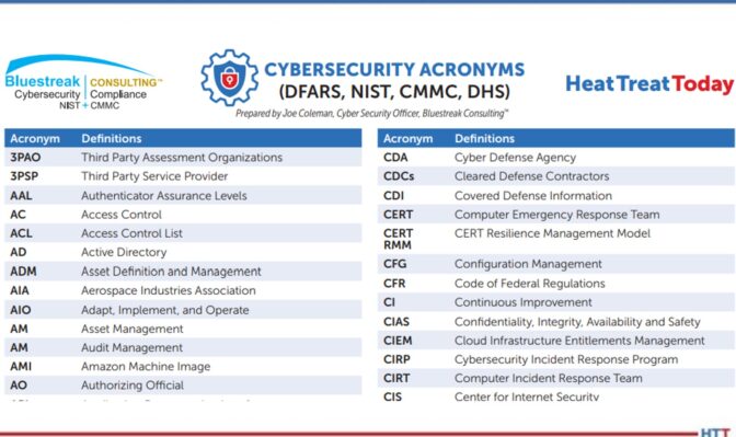
Source: Bluestreak Consulting™

This 9th article in the series from Heat Treat Today’s Cybersecurity Desk will explain the significance of 2FA (2-Factor Authentication) and MFA (Multi Factor Authentication), their benefits, and how they can help secure your data and your clients’ data.

2FA and MFA have proven to be effective methods to enhance online security. And, if you provide any products or services to a DoD (Department of Defense) contractor, this is mandatory for all users accessing your computer systems and critical data. Implementing 2FA is a minimum requirement and is better than just a username/password combination. MFA takes your security to a whole new level.

What Is 2FA?

2FA adds an extra layer of security to the usual username/password combination. It requires users to provide a second authentication factor, typically something they possess, in addition to their password. Common examples include a one-time verification code sent via SMS, email, or generated by an authentication app like Google Authenticator or Authy. By requiring the combination of something known (password), along with something possessed (authentication factor), an additional level of security is provided.

What is MFA?

The strengths of Multi-Factor Authentication (MFA) take security a step further by incorporating multiple authentication factors beyond the customary two. These authentication factors can be categorized into three main types: something you know (password or PIN), something you have (smartphone or security token), and something you are (biometrics like fingerprints or facial recognition). MFA offers increased security as it requires multiple factors to be verified before granting access.

Is MFA Better than 2FA?

In terms of security, the more the better should be the correct mindset. MFA is a more secure method than 2FA, because a user must respond to more checkpoints, especially if authentication factors disperse through different access points that aren’t available online (like a token or security key) and require a physical presence. Proving user identity multiple times instead of just submitting items of proof twice (i.e., 2FA), lowers the chance of a breach and helps achieve security compliance requirements.

Implementing 2FA or MFA

Enabling 2FA and MFA is becoming a more and more accessible option across many platforms and services. The most popular websites, email providers, social media networks, and online banking institutions offer 2FA and/or MFA options. Users can typically find the necessary settings in their account security or privacy preferences. It is crucial to follow the provided instructions for setting up and managing these authentication methods properly. In an age where cyber threats are always rising, protecting our online presence is critical. 2FA and MFA have proven to be effective methods in safeguarding our digital lives. By implementing these extra layers of security, companies can enhance their defenses and protect their data and their clients’ data.

What About Your Outside Personnel Support?

Chart with Cybersecurity Acronyms
Click on the Image for a full list of Cybersecurity Acronyms

Many companies have outside vendor support, and maintenance personnel access their network and systems on a regular basis. For example, they may use VPN access that requires the user to “punch a hole” in the firewall, making it much more vulnerable to unauthorized access. Additionally, it is typically a configuration nightmare for your network and the IT folks to get it working properly.

There is a better way. Through much research and testing, we have found that BeyondTrust is a great tool to use to allow outside vendors secure access to the information they need to see without connecting to your network. It is currently used by 20,000+ organizations worldwide with much success and security. BeyondTrust also records their entire online session so you can see exactly what they accessed and did during the online session. Check out www.beyondtrust.com for more information.

About the Author:

Joe Coleman is the cybersecurity officer at Bluestreak Consulting™, which is a division of Bluestreak | Bright AM™. Joe has over 35 years of diverse manufacturing and engineering experience. His background includes extensive training in cybersecurity, a career as a machinist, machining manager, and an early additive manufacturing (AM) pioneer. Contact Joe at joe.coleman@go-throughput.com.


Find heat treating products and services when you search on Heat Treat Buyers Guide.com


Cybersecurity Desk: Not Using 2FA or MFA? Your Data Is Not Secure Read More »

Castool Heat Treat Capabilities Expand with Nitrocarburizing

Castool Tooling Systems, a tooling provider to extrusion and die-casting companies, expanded its in-house capabilities with a nitrocarburizing system.

The new pit-type nitrocarburizing furnace, a model NX-1625 from Nitrex, is capable of processing large workloads of up to 6000 kg (13,200 lb.) with dimensions of 1550 mm (61”) in diameter and 2500 mm (98.5”) in height. The turnkey solution includes Nitreg®-C controlled nitrocarburizing and ONC® post-oxidation technologies, which can treat shot sleeves made of H13 tool steel while improving strength and longevity and preventing distortion when used in high-temperature and corrosive environments.

Nikola Dzepina
Nikola Dzepina
Account Manager
Nitrex
Source: NITREX

Commenting on the recent nitrocarburizing furnace, Nikola Dzepina, account manager at Nitrex, notes, "[Castool, a division of Exco Technologies] have been outsourcing nitriding to our heat treating services for many years and have been impressed with the quality of service and customer experience."

The large capacity furnace is part of a significant investment project that saw several furnace OEM suppliers collaborating to outfit the New Market, Canada, facility with various pieces of heat treating process equipment.


Find heat treating products and services when you search on Heat Treat Buyer's Guide.com


Castool Heat Treat Capabilities Expand with Nitrocarburizing Read More »

Exo Gas Composition Changes, Part 1: Production

Exothermic gas undergoes a few metamorphoses from the time it is produced to the time it is cooled down after use. Explore the transformations that occur within the combustion chamber to discover the impact these phases can have on the heat treatment atmosphere of your workpieces.

This Technical Tuesday article was composed by Harb Nayar, president and founder, TAT Technologies LLC. It appears in Heat Treat Today's August 2023 Automotive Heat Treating print edition.


Background

Harb Nayar
President and Founder
TAT Technologies LLC
Source: LinkedIn

Exothermic gas, more commonly referred to as Exo gas, is produced by partial combustion of hydrocarbon fuels with air in a well-insulated reaction or combustion chamber at temperatures well above 2000°F. Immediately after they exit the combustion chamber, the reaction products are cooled down using water to a temperature below ambient temperature to avoid condensation. The typical dew point of the cooled down Exo gas is about 10°F above the temperature of the water used to cool down. The cooled down Exo is then delivered to the heat treat furnaces where it gets reheated to the operating temperatures between 300°F and 2100°F.

Contact us with your Reader Feedback!

A simplified schematic flow diagram of Exo gas production followed by its cool down below ambient temperature and its final use in heat treat furnaces is shown in Figure 1.

The following aspects of the Exo gas production are clear from Figure 1:

  1. There is lot of energy lost out of the reaction chamber.
  2. There is additional heat lost during cooling using water.
  3. A good deal of water is used for cooling.
  4. The cooled down Exo gas is re-heated to the process temperature in heat treat furnaces.

Exo gas has been predominantly used and is still being used as a source of nitrogen rich atmosphere for purging, blanketing, and mildly oxide reducing applications in the heat treat and metal working industries.

Figure 1. Schematic flow diagram showing Exo production, cool down, and its use.
Source: Morris, “Exothermic Reactions,” 2023

Examples of applications:

  • Brazing
  • Annealing
  • Hardening
  • Normalizing
  • Sintering
  • Tempering, etc.

Examples of materials:

  • Irons
  • Steels
  • Electrical steels
  • Copper
  • Copper-base alloys
  • Aluminum
  • Jewelry alloys

Examples of product sizes and shapes:

  • Tubes
  • Rods
  • Coils
  • Sheets
  • Plates
  • Components
  • Small parts, etc.

Exo is the lowest cost gas used in furnaces operating at temperatures above about 700°F to keep air out and provide a protective atmosphere with some oxide reducing potential to the materials being thermally processed.

There are two types of Exo gases: lean Exo gas, with mostly nitrogen and carbon dioxide and very little hydrogen, and rich Exo gas, with a little less nitrogen and carbon dioxide and substantially more hydrogen and some carbon monoxide. Typical compositions are given below:

  • Lean Exo: 80–87% Nitrogen; 1–2% Hydrogen; 2–4% H20; 1–2% CO; 10–11% CO2
  • Rich Exo: 70–75% Nitrogen; 9–12% Hydrogen; 2–4% H20; 7–9% CO; 6–7% CO2
Figure 2. Exo gas operating range
Source: SECO/WARWICK

Figure 2 shows graphs of Exo gas composition at various air to natural gas ratios. H2, CO, and residual CH4 decreases with increasing air to natural gas ratio whereas CO2 goes in the opposite direction. H20 content not shown in the graphs is typically in the 2–4% range depending upon the temperature and cooling efficiency of the cooling system. N2 is the balance which increases with increasing air to natural gas ratio.

The generator designs to produce lean and rich Exo gases are slightly different as shown in the schematic flow diagrams below in Figures 3 and 4.

Objective

This paper will demonstrate a simplified software program (harb-9US) developed recently by TAT Technologies LLC that can easily calculate the reaction products composition, temperature, exothermic energy released, various ratios, and final dew point for various combinations of air and fuel flows entering the reaction chamber at a predetermined temperature and pressure.

The data presented in this paper is under thermodynamically equilibrium conditions only, captured when the reaction is fully completed. It does not tell how long it will take for the reaction to reach completion. However, it can be safely said that reactions are completed relatively fast at temperatures above about 1500°F and very slow at temperatures below about 1000°F. The current software program uses U.S. units: flow in SCFH, pressure in PSIG, temperature in degrees Fahrenheit, and heat as enthalpy in BTU.

The composition of the Exo gas for a fixed incoming air to hydrocarbon fuel ratio changes from production in the combustion chamber to the cool down equipment to bring the Exo gas to below the ambient temperature and finally into the furnace where the material is being heat treated.

Understanding the changes in gas composition from Step 1 (Production in the Combustion Chamber) to Step 2 (Cool Down to Ambient Temperature) to Step 3 (At Temperature of Heat Treated Part) can help to improve the composition, quality, and control of Exo gas that will surround the metallic products being heat treated in the furnace.

Figure 3. Lean Exo generator schematic flow diagram
Source: SECO/WARWICK

Step 1: Composition of Exo Gas as Produced in the Combustion Chamber

Table A shows the Exo gas compositions as generated within the combustion chamber at various air to natural gas ratios supplied at 100°F and 0.1 PSIG. In these calculations natural gas composition is assumed as 100% CH4 and air is assumed as 20.95% oxygen and balance nitrogen. CH4 is fixed at 100 SCFH and air flow is varied to give air to natural gas ratios between 9 and 6. Typically a ratio of 9 is used for lean Exo and 7 is used for rich Exo applications. Other ratios are used in some special applications.

Table A: Exo gas compositions in reaction chamber based on 100 SCFH of CH4 with air 900, 850, 800, 750, 700, 650, and 600 SCFH to give air to natural gas (CH4) ratios of 9, 8.5, 8, 7.5, 7, 6.5 and 6 respectively. Air and natural gas (CH4) are at 100°F before entering the combustion chamber.
Source: TAT Technologies LLC

The following key conclusions can be made from Table A as one moves from air to natural gas (CH4) ratio of 9 down to 6:

  1. The peak temperature in the reaction chambers goes from a high of 3721°F down to low of 2865°F. Because of high temperatures, good insulation around the combustion chamber is a must. A significant portion of the exothermally generated energy within the reaction chamber is lost to the surroundings.
  2. There is no residual CH4 in the Exo gas composition at these high temperatures. There is no soot (carbon residue) under equilibrium conditions.
  3. H20 content in the natural gas (CH4) gas in the reaction chamber is very high — from high of 19.11% to low of 15.87%. These correspond to dew point 139°F to 132°F — well above the ambient temperature. Because of the very high dew point, the Exo gas coming out of the reaction chamber must be cooled down below the ambient temperature to remove most of the H20 in the Exo gas to avoid any condensation in the pipes carrying the Exo gas toward the furnace and into the
    furnace.
  4. H2% changes significantly from 0.67% to 9.96%.
  5. The oxide reducing potential (ORP) as measured by H2/H20 ratio changes from a very low of 0.035 to 0.628. ORP in the reaction chamber is overall quite low because of high percentage of H20.
  6. Nitrogen content varies from 70.34% to 61.26% of the total Exo gas in the reaction chamber.
  7. Exothermic heat generated varies from 95.3 MBTU to 54.34 MBTU — it gradually becomes a less exothermic reaction. Gross heating value of CH4 (at full combustion) is 101.1 MBTU/100 cubic foot of CH4.
Figure 4: Rich Exo generator schematic flow diagram
Source: SECO/WARWICK

Question: What happens to the composition of Exo gas as it cools from peak temperature in the combustion chamber to different lower temperatures after it exits from the combustion chamber?

Answer: It changes a LOT, assuming enough time is provided to reach its equilibrium values during cooling down to any specific temperature. Whenever there is a mixture of gases, such as CH4, H2, H20, CO, CO2,O2, N2, there are a variety of reactions going on between the constituents in the reactant gases to produce different combinations of gas products and heats (absorbed or liberated) at different temperatures. The most popular and well-known reactions are:

  • Partial Oxidation Reaction: CH4+ 1/2O2 → CO + 2H2 — exothermic. The reaction becomes more exothermic as O2 increases from 0.5 to 2.
  • Water Gas Shift Reaction: CO + H20 → CO2 + H2 — slightly exothermic. It usually takes place at higher temperatures faster. A catalyst in the reaction chamber can help to lower the high temperature requirement. There are many catalysts. Commonly used are either Ni or precious metals.
  • Steam Reforming Reaction: CH4 + H20 → CO + 3H2 — highly endothermic.
  • CO2 Reforming Reaction: CH4 + CO2 → 2CO + 2H2 — endothermic.

All of these reactions have different degrees of influences from changes in temperature. One could say that the final equilibrium composition of the Exo gas is a continuously moving target as temperature changes. Only the N2 portion stays constant. One can make the following generalized statements covering a broad range of Exo gases (lean and rich) in the reaction chamber:

a) N2 content does not change. It remains neutral at all temperatures.
b) H2 content decreases with increasing temperature.
c) H20 (vapor) content increases with increasing temperature.
d) CO content increases with increasing temperature.
e) CO2 content decreases with increasing temperature.
f) Residual CH4 decreases with increasing temperature.
g) Soot decreases with increasing temperature.
h) Catalysts facilitate the speed of reactions at any temperature.

Conclusion

Exo gas composition changes during its time in the combustion chamber. Reaction products composition, temperature, exothermic energy released, various ratios, and final dew point are all items that need to be taken into consideration to protect the metallic pieces that will be heat treated in the resulting atmosphere. Part 2 will demonstrate this principle and discuss Step 2 (Cool Down to Ambient Temperature) and Step 3 (At Temperature of Heat Treated Part).

About the author:

Harb Nayar is the founder and president of TAT Technologies LLC. Harb is both an inquisitive learner and dynamic entrepreneur who will share his current interests in the powder metal industry, and what he anticipates for the future of the industry, especially where it bisects with heat treating

For more information:

Contact Harb at harb.nayar@tat-tech.com or visit www.tat-tech.com.

References:

Herring, Dan. “Exothermic Gas Generators: Forgotten Technology?” Industrial Heating, 2018. https://digital.bnpmedia.com/publication/m=11623&i=534828&p=121&ver=html5.

Morris, Art. “Exothermic Reactions.” Industrial Heating (June 10, 2023), https://www.industrialheating.com/articles/91142-exothermic-atmospheres.


Find heat treating products and services when you search on Heat Treat Buyers Guide.com


Exo Gas Composition Changes, Part 1: Production Read More »

Solar Atmospheres of Souderton, PA Adds Furnace for Titanium Reclamation

HTD Size-PR LogoSolar Atmospheres Souderton, PA incorporated a high-production vacuum furnace with a work zone of 48"x48"x72" and a weight capacity of up to 7,500 lbs/batch. The furnace doubles the facility's hydriding and de-hydriding capacity in the reclamation of titanium and tantalum materials.

Solar Atmospheres Souderton, PA installed the furnace with Solar Manufacturing's vacuum furnace technology. The technology is aimed at safety and efficiency and will help in the reclamation process.

Solar Atmospheres of Souderton, PA Adds Furnace for Titanium Reclamation Read More »

Aluminum Industry Sees Expansion in Canada

Aluminerie Alouette, based in Sept-Îles, Quebec, Canada, announced several investments in its aluminum smelting operations. These include upgrades to anode baking furnaces as well as a planned installation of new potline technologies that will address waste streams at the site. The Canadian aluminum producer’s new technologies will increase operations and address environmental issues.

Alouette restarted the first firing ramps of its No. 1 (ABF-1) anode baking furnace after a refractory relining project, which was completed with EPCM support from Hatch. With furnace No. 1 restarted, the companies are now beginning work on the restart of a second furnace reline (ABF-2), which is expected to be completed in 2024.

Additionally, Alouette signed two contracts totaling $2.7 million with PyroGenesis Canada Inc. The first contract will address the treatment of spent pot lining (SPL) waste. The technology proposed will use plasma arc thermal treatment to transform the carbonaceous and refractory materials contained in SPL into synthesis gas and aluminum fluoride. The objective of the second contract is to process excess electrolytic bath in a plasma arc thermal treatment plant with the goal of producing aluminum fluoride.


Find heat treating products and services when you search on Heat Treat Buyers Guide.com


Aluminum Industry Sees Expansion in Canada Read More »

Discover the DNA of Automotive Heat Treat: Thru-Process Temperature Monitoring

In addressing the challenges of modern automated production flow, thru-process temperature monitoring and process validation strategies provide viable options in the automotive heat treat industry. Could they help your operations?

This Technical Tuesday article was composed by Steve Offley, “Dr. O,” product marketing manager, PhoenixTM. It appears in Heat Treat Today’s August 2023 Automotive Heat Treating print edition.


The Heat Treat Monitoring Goal

Dr. Steve Offley, “Dr. O”
Product Marketing Manager
PhoenixTM
Source: LinkedIn

In any automotive heat treatment process, it is essential that the heat treat application is performed in a controlled and repeatable fashion to achieve the physical material properties of the product. This means the product material experiences the required temperature, time, and processing atmosphere to achieve the desired metallurgical transitions (internal microstructure) to give the product the material properties to perform it’s intended function.


When tackling the need to understand how the heat treat process is performing, it is useful to split the task up into two parts: focusing on the furnace technology first, and then introducing the product into the mix.

If we consider the furnace performance, we need to validate that the heat treat technology is capable of providing the desired accurate uniformity of heating over the working volume of the furnace for the desired soak time where the products are placed. This is best achieved by performing a temperature uniformity survey (TUS). The TUS is a key pyrometry requirement of the CQI-9 Heat Treat System Assessment (AIAG) standard applied by many automotive OEMs and suppliers.

Traditionally temperature uniformity surveys are performed using a field test instrument (chart recorder or static data logger) external to the furnace with thermocouples trailing into the furnace heating chamber. Although possible, this technique has many limitations, especially when applying to the increasingly automated semi or continuous operations discussed later in this article.

Thru-process Temperature Profiling — Discover the Heat Treat DNA

When it comes to heat treatment, the TUS operation gives a level of confidence that the furnace technology is in specification. However, it is important to understand the need to focus on what is happening at the real core of the product from a temperature and time perspective. Product temperature profiling, as its name suggests, is the perfect technique. Thermocouples attached to the part, or even embedded within the part, give an accurate record of the product temperature at all points in the process, referred to as a product temperature profile. Such information is helpful to determine process variations from critical factors such as part size, thermal mass, location within the product basket, furnace loading, transfer rate, and changes to heat treat recipe. Product temperature profiling by trailing thermocouples with an external data logger (Figure 1) is possible for a simple batch furnace, but it is not a realistic option for some modern heat treat operations.

Figure 1. Typical TUS survey set-up for a static batch furnace. PhoenixTM PTM4220 External data logger connected directly to a 9 point TUS frame used to measure the temperature uniformity over the volumetric working volume of the furnace.
Source: PhoenixTM

With the industry driving toward fully automated manufacturing, furnace manufacturers are now offering the complete package with full robotic product loading — shuttle transfer systems and modular heat treat phases to either process complete product baskets or one-piece operations.

The thru-process monitoring principle overcomes the problems of trailing thermocouples as the multi-channel data logger (field test instrument) travels into and through the heat treat process protected by a thermal barrier (Figure 2).

Figure 2. PhoenixTM thru-process monitoring system. (1) The thermal barrier protects internal multi-channel data logger, (2) the field test instrument, (3) the product thermal profile view, (4) the temperature uniformity survey (TUS), and (5) short nonexpendable mineral insulated thermocouples.
Source: PhoenixTM

The short thermocouples are fixed to either the product or TUS frame. Temperature data is then transmitted either live to a monitoring PC running profile or the TUS analysis software via a two-way RF (radio frequency) telemetry link or downloaded post run.

Although thru-process temperature monitoring in principle can be applied to most heat treat furnace operations, obviously no one solution will suit all processes, as we know from the phrase, “One size doesn’t fit all.”

For this very reason, unique thermal barrier designs are required to be tailored to the specific demands of the application whether temperature, pressure, atmosphere, or geometry as described in the following section.

Product Profiling and TUS in Continuous Heat Treat Furnaces

Thru-process product temperature profiling and/or surveying of continuous furnace operations, unlike trailing thermocouples, can be performed accurately and safely as part of the conventional production flow allowing true heat treat conditions to be assessed. As shown in Figure 3, surveying of the furnace working zone can be achieved using the plane method. A frame attached to the thermal barrier positions the TUS thermocouples at designated positions relative to the two dimensional working zone (furnace height and width) as defined in the pyrometry standard (CQI-9) during safe passage through the furnace (soak time).

Figures 3. Temperature uniformity survey of a continuous furnace using the plane method applying the PhoenixTM thru-process monitoring system. The data logger travels protected in a thermal barrier mounted on the TUS frame performing a safe TUS at four points across the width, which is impossible with trailing thermocouples.
Source: : Raba Axle, Györ, Hungary

Sealed Gas Carburizing and Oil Quench Monitoring

For traditional sealed gas carburizing where product cooling is performed in an integral oil quench, the historic limitation of thru-process temperature profiling has been the need to bypass the oil quench and wash stations.

In such carburizing processes, the oil quench rate is critical to both the metallurgical composition of the metal and to the elimination of product distortion and quench cracks, and so the need for a monitoring solution has been significant. Regular monitoring of the quench is important as aging of the oil results in decomposition, oxidation, and contamination of the oil, all of which degrade the heat transfer characteristics and quench efficiency.

To address the process challenges, a unique barrier design has been developed that both protects the data logger in the furnace (typically 3 hours at 1700°F/925°C) and during transfer through the oil quench (typically 15 minutes) and final wash station.

Figures 4. PhoenixTM thru-process temperature profiling system monitoring the core temperature of automotive parts in a traditional sealed gas carburizing furnace with integral oil quench. (left) System entering carburizing furnace in product basket. (right) Thermal barrier showing outer structural frame and sacrificial insulation blocks protecting inner sealed thermal barrier housing the data logger.
Source: PhoenixTM

The key to the barrier design is the encasement of a sealed inner barrier (Figure 4) with its own thermal protection with blocks of high-grade sacrificial insulation contained in a robust outer structural frame. The innovative barrier offers complete protection to the data logger allowing product core temperature monitoring for the complete heat treat process under production conditions.

Low Pressure Carburizing with High Pressure Gas Quench

In the current business environment, an attractive alternative to the traditional sealed gas carburizing application for both energy and environmental reasons is low pressure carburizing (LPC). Following the vacuum carburizing process, the product is transferred to a sealed high-pressure gas quench chamber where the product is rapidly gas cooled using typically N2 or Helium at up to 20 bars.

Such technology lends itself to automation with product baskets being transferred by shuttle drives and robot loading mechanisms from chamber to chamber in a semi-continuous fashion. The sequential processing (with stages often being performed in self-contained sealed chambers) can only be monitored by the thru-process approach where the system (thermal barrier protected data logger) is self-contained within the product basket or TUS frame.

In such processes the technical challenge is twofold. The thermal barrier must be capable of protecting against not only heat during the carburizing phase, but also very rapid pressure and temperature changes inflicted by the gas quench. To protect the thermal barrier in the LPC process with gas quench, the barrier construction needs to be able to withstand constant temperature cycling and high gas pressures. The design and construction features include:

  • Metal work: 310 stainless steel to reduce distortion at high temperature combined with internal structural reinforcement
  • Insulation: ultra-high temperature microporous insulation to minimize shrinkage problems
  • Rivets: close pitched copper rivets reduce carbon pick up and maintain strength
  • Lid expansion plate: reduces distortion during rapid temperature changes
  • Catches: heavy duty catches eliminating thread seizure issues
  • Heat sink: internal heat sink to provide additional thermal protection to data logger

During the gas quench, the barrier needs to be protected from Nitrogen N2 (g) or Helium He(g) gas pressures up to 20 bar. Such pressures on the flat top of the barrier would create excessive stress to the metal work and internal insulation or the data logger. Therefore, a separate gas quench deflector is used to protect the barrier. The tapered top plate deflects the gas away from the barrier. The unique design means the plate is supported on either four or six support legs. As it is not in contact with the barrier, no force is applied directly to the barrier and the force is shared between the support legs.

In LPC technology further monitoring challenges are faced by the development of one piece flow furnace designs.

Figures 5. (left) Thermal barrier being loaded into LPC batch furnace with TUS frame as part of temperature uniformity survey. (right) Thermal barrier shown with independent quench deflector providing protection during the high pressure gas quench.
Source: PhoenixTM

New designs incorporate single piece or single product layer tray loading into multiple vertical heat treat chambers followed by auto loading into mobile high pressure quench chamber. Miniturization of each separate heat treat chamber limits the space available to the monitoring system. The TS02-128-1 thermal barrier has been designed specifically for such processes utilizing the compact 6 channel “Sigma” data logger allowing reduction of the footprint of the system to fit the product tray and reduce thermal mass. With a height of only 128 mm/5 inch and customized independent low height quench deflector, the system is suitable for challenging low height furnace chambers and offers 1 hour protection at 1472°F/800°C in a vacuum.

Figure 6. (left) Low profile TUS system (TS02-128-1 thermal barrier six channel Sigma data logger) designed with TUS surveying individual one-piece flow heat treatment LPC furnace chambers (right) Thermal barrier shown with optional low profile gas quench deflector.
Source: PhoenixTM

Rotary Hearth Furnace Monitoring — Solution Reheat of Aluminum Engine Blocks

In modern rotary hearth furnaces (Figure 7), temperature profiling using trailing thermocouples is impossible as the cables would wind up in the furnace transfer mechanism. Due to the central robot loading and unloading and elimination of charging racks/baskets, the use of a conventional thru-process system would also be a challenge.

Figure 7. A modern rotary hearth furnace.
Source: PhoenixTM

To eliminate the loading restrictions, a unique thermal barrier small enough to fit inside the cavity of the engine block and allow automated loading of the complete combined monitoring system and product has been developed. To optimize the thermal performance of the thermal barrier with such tight size constraints, a phased evaporation technology is employed. Thermal protection of the high temperature data logger is provided by an insulated water tank barrier design keeping the operating temperature of the data logger at a safe 212°F/100°C or less. The system allowed BSN Thermoprozesstechnik GmbH in Germany to commission the furnace accurately and efficiently and thereby optimize settings to not only achieve product quality but also ensure energy efficient, cost effective production.

Summary

Thru-process product temperature profiling and surveying provide a versatile, accurate, and safe solution for monitoring increasingly automated, intelligent furnace lines and the means to understand, control, optimize, and certify your heat treat process.

About the author:

Dr. Steve Offley, “Dr. O,” has been the product marketing manager at PhoenixTM for the last five years after a career of over 25 years in temperature monitoring focusing on the heat treatment, paint, and general manufacturing industries. A key aspect of his role is the product management of the innovative PhoenixTM range of thru-process temperature and optical profiling and TUS monitoring system solutions.

For more information:

Contact Steve at Steve.Offley@phoenixtm.com.


Find heat treating products and services when you search on Heat Treat Buyers Guide.com


Discover the DNA of Automotive Heat Treat: Thru-Process Temperature Monitoring Read More »

Mesh Belt Temper Furnace Shipped, More To Come

The first of five new mesh belt temper furnaces was shipped from Michigan manufacturer to the southern U.S. The second and third furnaces are ready for the next phases of production, and they all will be used for preheating and tempering of steel bar stock.

Premier Furnace Specialists, Inc./BeaverMatic has scheduled the first installation for the last week of August. The remaining four will be completed and installed through January 2024. These furnaces are natural gas fired with an operating temperature of 1600°F. They have thirty-six inch wide mesh belts capable of 2000 lbs per hour. The furnaces are all operated through a 23.8” HMI color touch screen interface.

Mesh belt furnace from Premier Furnace Specialists, Inc./BeaverMatic
Source: Premier Furnace/BeaverMatic

“We built them a similar furnace in 2022,” commented Steve Ignash, sales engineer at Premier. “The [latest] system was designed, built, and tested at our new 40,000 square foot facility in Farmington Hills, MI.”


Find heat treating products and services when you search on Heat Treat Buyers Guide.com


Mesh Belt Temper Furnace Shipped, More To Come Read More »

Heat Treat Hardening Capabilities Increase for Hydraulics Manufacturer

A set of nitriding/nitrocarburizing systems has been installed for a European hydraulics manufacturer. The furnaces help produce components for hydraulic pumps and motors and strengthen the company’s in-house heat treatment capabilities.

The furnaces are from Nitrex – a company based in North America with international locations. This is the second set of systems from the same manufacturer. These systems primarily serve to nitride/nitrocarburize pieces made from various steels and alloys and will help meet the growing demand for hydraulic components.

Hydraulics systems expand heat treat capabilities
Source: Nitrex

“The nitriding/nitrocarburizing furnaces have [. . . integrated] seamlessly into our customer’s operations,” commented Mark Hemsath, vice president of sales, furnaces & heat treating services at Nitrex.


Find heat treating products and services when you search on Heat Treat Buyers Guide.com

Heat Treat Hardening Capabilities Increase for Hydraulics Manufacturer Read More »

Induction and Sustainability Tips Part 4: Vacuum Furnace and Heat Treat Energy Savings

Discover expert tips, tricks, and resources for sustainable heat treating methods Heat Treat Today’s recent series. Part 4, today’s tips, covers induction heating, quench, and insulation tips. We’ve added resources towards the end of today’s post for further enrichment.

This Technical Tuesday article is compiled from tips in Heat Treat Today’s May Focus on Sustainable Heat Treat Technologies print editionIf you have any tips of your own about induction and sustainability, our editors would be interested in sharing them online at www.heattreattoday.com. Email Bethany Leone at bethany@heattreattoday.com with your own ideas!


1. Tips for Induction Hardening


Contact us with your Reader Feedback!

What are the benefits of induction hardening? Here are a few:

  • Saves space: Induction hardening requires minimum space required in comparison with furnaces
  • Saves energy: Induction heating equipment does not need to be kept running when not in use
  • Clean: Induction heating equipment requires no combustion gases
  • Energy-efficient: Only a small proportion of the material needs to be heated
  • Minimize deformation: Induction hardening requires no applied force
  • Save maintenance costs: Inductor coils have a long life, reducing the need for maintenance

Source: Humberto Torres Sánchez, Chief Metallurgist, ZF Group

#induction hardening #deformation #zerocombustiongas

2. Insulation = Key for Energy Savings in Vacuum Furnaces

Look for insulation quality in your next vacuum furnace.
Source: NITREX

Improvements in insulation materials are also contributing to greater energy efficiency of vacuum furnaces. Most furnaces on the market today have a 1” (25.4 mm) graphite board with bonded Grafoil and two layers of graphite felt. However, the insulation performance of a 1” (25.4 mm) graphite board is about 25% less efficient than a 1” (25.4 mm) graphite felt. For processes that require high operating temperatures, typically over 2,200°F (1,204°C), an all graphite felt that is 2” or 2.5” thick (50.8 mm or 63.5 mm) minimizes heat loss inside the hot zone. Efficiency gains of up to 25% are possible over the standard 1” (25.4 mm) board and 1” (25.4 mm) graphite felt insulation and an even greater gains at higher operating temperatures. To safeguard the graphite felt from mechanical harm and localized compression, these thicker all-graphite felt insulation configurations are usually covered with a carbon fiber composite (CFC) sheet about 0.050” (1.27 mm) thick.

Source: NITREX

#insulation #energysavings #graphite

3. Thinner Steel, Lighter Car

Fuel efficiency (and the stringent requirement for passenger safety) has raised the bar for the automotive industry to procure steel with high strength, hardness, and ability to fabricate. Reduction of weight requires lighter cars with thinner body material which can absorb impact. These dual contradictory properties of high hardness material which can be easily shaped can normally be achieved either by heat treat or through addition of alloys. These two processes are described below.

Normal heat treatment to produce small grains in the material will increase the hardness in steel but also create a propensity to fracture. Thus, a process known as quench and partition — where carbon diffusion from martensite to retained austenite to stabilize the latter — has been introduced. Further verification and prediction of the phases has been conducted using thermodynamics modeling for phase characteristics by Behera & Olsen at Northwestern University, Materials Science and Engineering.

The process starts with full automatization (or in some cases intercritical annealing) followed by fast quench to a defined quench temperature (QT) between the martensite start, Ms, and martensite finish, Mf, temperature. The steel is then reheated to the partition temperature (PT) and held there for a certain partition time followed by a quenching step again to room temperature, as shown in the image.

Quench and partition process
Source: Speer et al. The Minerals, Metals, & Materials Society 2003

The quenching step establishes the largely martensite matrix while the partition step helps stabilize the retained austenite by carbon partitioning. During the holding step, carbon diffuses from martensite to retained austenite and thus improves its stability against subsequent cooling or mechanical deformation. The final microstructure consists predominantly of tempered martensite and stabilized retained austenite with possibly a small amount of bainite formation and carbide precipitation during the partition step and fresh martensite formation during final quenching.

The other process to achieve high hardness and high ductility is by alloy addition in carbon steel. Over, 2,000 different types of steel exist. A new type of steel that is extremely strong, but simultaneously ductile is used in the automotive industry. Small quantities of elements like vanadium or chrome in steel promotes ductility. They are not brittle; however, up until now they have not been strong enough to enable the construction of car bodies with thinner sheets.

In the crystals of steels, the atoms are more or less regularly arranged. Steels become particularly ductile though if they can switch from one structure to another. This is because this process allows energy absorption, which can then no longer initiate any damage in the material. In a car body or other steel components, tiny areas then alternate with the two different atom arrangements.

Ductile steels have two coexisting crystal structures. The search produced an alloy made from 50% iron, 30% manganese and 10% respectively of cobalt and chrome (Max Planck Institutes).

Source: Madhu Chatterjee, PresidentAAT Metallurgical Services LLC

#quenchandpartition #quenchtemp

4. Tips for Selecting Induction Heating Equipment

“The following factors typically influence equipment design:

  • Material
  • Prior microstructure
  • Part geometry
  • Austenitizing temperature
  • Production rate
  • Power requirements, kW (typically selected by vendor based on information provided)
  • Frequency selection, kHz (typically selected by vendor based on information provided)
  • Pattern/profile (i.e., shape of heating area)
  • Coil design (typically selected by vendor based on information provided)
  • Process-development requirements
  • Application-specific criteria (e.g., water vs. polymer quenching)
  • Method of loading and unloading the workpiece (e.g., manual or robotic)
  • Stock removal after heat treatment
  • Type of tempering (i.e., furnace/oven vs. induction)”

SourceDan Herring, The Heat Treat Doctor®, Atmosphere Heat Treatment, vol. 1, 2014, pp. 656.

#inductionequipment #inductiondesign

5. Additional Resources on Induction Heating, Quench, and Insulation

Read more about the processes when you click on these articles:


Find heat treating products and services when you search on Heat Treat Buyers Guide.com


Induction and Sustainability Tips Part 4: Vacuum Furnace and Heat Treat Energy Savings Read More »

ThermTech Expands in Wisconsin

A heat treat company based in Waukesha, WI, has expanded with a 95,000 square foot building in New Berlin, WI. The New Berlin facility is seven miles from their Travis Road campus.

Steve Wiberg and Mary Wiberg Springer, owners of ThermTech, share that the plant’s square footage will be 270,000. The new space will be used for the company’s expansion. The new facility will allow the heat treater to continue to meet their clients’ needs as they expand their core offerings: hardening, tempering, surface heat treatment, carburizing, vacuum treatments, annealing, press quenching, austempering, and aluminum heat treatment.


Find heat treating products and services when you search on Heat Treat Buyers Guide.com


ThermTech Expands in Wisconsin Read More »