Al-u-MI-ni-um. A-LU-mi-num. Heat treating aluminum is not something we often get a chance to talk about, but it is everywhere. From the bikes we ride to the foil bound around last night's burger, this light-weight metal certainly has a place in our daily life. Today's Technical Tuesday original content article highlights some of our favorite aluminum processing features over the years.
Aluminium is the most widely available lightweight bike frame material, up to three times lighter than steel frames. It provides the low weight, stiff, durable, rust resistance, and affordable ride that we look to enjoy up mountains, through city roads, and along park trails. But aluminum also has a bunch of other uses, as in the medical and automotive industries. How is this lightweight metal heat treated? Let's review these three content pieces from Heat TreatToday'sfiles.
Combatting Corundum
Taking it a step back to aluminum melting and refractory, hear what Dan Szynal, VP of Engineering & Technical Services at Plibrico, has to share about the causes and mediation of corundum growth.
What better way to learn about aluminum processing and heat treat rather than watching it happen in this 1940s-1950s video? It's got the classic black & white, intense masculine voice narrator, and the illustrated graphics everyone loves. What do you think of this 22 minute video? Let us know!
"When fully developed and implemented," this piece of news reads, "it will eliminate direct greenhouse gas emissions from the smelting process and strengthen the closely integrated Canada-United States aluminum and manufacturing industry." Learn more about this innovative process for aluminum processing and then compare with current greenhouse advances in the steel industry.
Summer is slipping away, is it time to go back to school? Heat TreatToday is sharing some of the training resources that you should consider if you're committed to increasing your heat treat knowledge.
The resources in this original content article come from Heat TreatToday's 2021 Trade ShowSeptember print edition. If you have a training resource that we missed send your own top pick to Karen@HeatTreatToday.com to be published in the 2022 print edition!
There’s nothing like gathering with fellow industry colleagues at in person seminars, conferences, and classes to learn the basics, the newest trends, and everything in between. Check out the different training opportunities and organizations that provide lessons and courses.
AP University
Dan Hill, AFC-Holcroft: "Applied Process offers their AP University by invitation to train attendees in the benefits, design, and manufacture of austempered ductile iron and austempered steel components. The two-day program includes classroom instruction by several presenters combined with a heat treat plant tour and a ductile iron foundry demonstration. I was fortunate to attend this thorough training and enjoyed all the interaction with presenters. I would recommend this training for prospective customers’ product designers, metallurgists, and quality personnel as the use of austempered components continues to rapidly increase."
Tom Morrison, Metal Treating Institute: "MTI’s online academy has 5 different certificate programs in the areas of technical knowledge, management skills and plant safety. MTI’s online academy meets training guidelines for Nadcap, ARP 1962, ISO9000 and AS9100. Check out the specific certificate programs."
Justin Bunzeluk, AFC-Holcroft: "AFC-Holcroft recently implemented our 'AFC-Holcroft University' courses, which were initially developed specifically for our own employees. Three levels of training, ranging from Basic to Advanced, were offered on a number of topics drilling deep into the technical aspects of equipment design and function. Each training session has been championed by an internal expert on the selected topic. Because the content of each of the 12+ courses is so highly specific to furnaces, we may decide to offer some sessions to customers in the future."
YES Management Training Program
Tracy Dougherty, AFC-Holcroft: "We have been fortunate enough to have had a number of employees over the years enrolled in MTI’s intensive YES Management Training Program. Our graduates have found the program to be well worth the time and travel investment, and AFC-Holcroft considers it an honor to nominate any of our employees to take part in the program."
ASM’s Practical Heat Treating and Basics of Heat Treating
Dan Hill, AFC-Holcroft: "ASM International offers several courses in self-study, virtual, and in-person format designed for the heat treating industry. These allow for great flexibility to get training completed at time and pace convenient for the trainee. I’ve attended both 'Practical Heat Treating' and 'Basics of Heat Treating' courses myself. These are excellent primers with a wealth of course material that I still refer back to from time to time as references."
Twice a month, Heat TreatToday publishes an episode of Heat TreatRadio, a unique-to-the-industry podcast. Whether it’s AMS2750 or CQI-9, these episodes will boost your knowledge about all things heat treat. Listen to these four episodes to gain confidence in compliance. Enjoy this original content, and happy listening!
Justin Rydzewski Director of Sales & Market Development Controls Service, Inc.
Heat TreatRadio: Justin Rydzewski on CQI-9 Rev.4 (Part 1 of 4) – Pyrometry
In this episode of Heat TreatRadio, hear directly from a committee member involved in updating CQI-9. Justin Rydzewski, director of Sales and Marketing at Controls Service, Inc. sheds some light on the automotive equivalent to AMS2750: CQI-9. From translation issues and formatting to new process tables and caveats regarding thermocouples, this episode of Heat TreatRadio provides all the necessary information heat treaters need to use the new revision. It's about more than just pyrometry; it's also about heat treat system assessment and heat treat operation.
To get the run-down on CQI-9, listen to this episode of Heat TreatRadio.
"How like is one test to the next one? What is your means of collecting data and what is your response plan when that data is unfavorable? Having that predetermined, so that you’re not doing in on the fly, can be incredibly helpful."
Heat TreatRadio: Andrew Bassett on AMS2750F (Part 1 of 3)
Andrew Bassett, President, Aerospace Testing and Pyrometry
In this three-part episode, Andrew Bassett of Aerospace Testing and Pyrometry discusses all things AMS2750F. Questions on thermocouples, calibrations and thermal processing classification, SATs, or TUSs? This series of Heat TreatRadio episodes has the answers.
In this first episode, Andrew focuses on thermocouples and sensors and the different thermocouple types that AM2750 Revision F addresses compared to past revisions. The use of nickel/nickel-moly thermocouples and the use of resistant temperature devices are just two of the additions found in Rev. F.
To get an overview of the changes to AMS2750 made in Revision F, as well as to hear a bit about the process for writing the specification book, listen to this series of episodes on Heat TreatRadio.
"I’m an end-user, so I’m able give my input and say, 'Hey, this doesn’t make sense. What you want to add into the spec is not real world.' It’s nice that people such as us get involved with these specifications."
Heat TreatRadio: Reimagining Furnace Compliance with C3 Data’s Matt Wright
Matt Wright Chief Marketing Officer, C3 Data Source: C3 Data
The future of compliance could be in the palm of your hand. Matt Wright, chief marketing officer at C3 Data, describes how C3 Data has encapsulated everything required to be AMS2750 or CQI-9 compliant into one platform: a user-friendly system that can run on a smart phone. No more clipboards, spreadsheets, or post-it notes. Using optical character recognition, heat treaters can complete SATs in real-time. With QR codes, operators can scan thermocouples and access the appropriate table within a specification book.
To learn more about what C3 Data is doing to make compliance easier, listen to this episode of Heat TreatRadio.
"When I look at our industry, one of the things that is the biggest challenge is the flow of information — getting information from where it resides to where it needs to be in the format that it needs to be."
Heat TreatRadio: Justin Rydzewski and James Hawthorne on CQI-9 Rev.4 (Part 3 of 4) – Process Tables & New Resources
James Hawthorne Corporate Heat Treat Specialist, Acument Global Technologies
There's more new material in CQI-9 Rev. 4 than just pyrometry updates. James Hawthorne of Acument Global Technologies, zooms in on changes to CQI-9's process tables and new resources. One of these new resources, a glossary of terms used within the document, was created specifically because of end-user requests. Maintenance request forms, helpful illustrations, and informative figures are just a few other new resources added to the latest version of CQI-9.
"Read the document. Read as much of it as you can and try to understand as much as you possibly can."
To hear more about what's new in CQI-9 Rev.4, listen to this episode of Heat TreatRadio.
Is the sky falling? Are we all doomed? Are we on the cusp of stagflation or hyper-inflation? Is this the beginning of the worst recession since the 1930s? The short answer is no.
Chris Kuehl, PhD, managing director of Armada and economic analyst at Industrial Heating Equipment Association, explains why the future may not be all doom and gloom. Read on to discover a positive outlook on the economy in this original content piece, originally published intheJune 2022 Heat TreatBuyers Guide print edition.
Chris Kuehl Managing Director, Armada, Economic Analyst, IHEA
The frothy coverage of the economy has been an exercise in extremes and one has to wonder why. Especially when we look at the actual data. The signals that are being sent are not all that dire. This is not to say that there are no problems to be aware of and there are most definitely some impending threats, but the near hysteria that shows up almost hourly is not justified by the facts — at least not as they are emerging right now. Why do some economists present these extremely pessimistic assessments and assert that a major catastrophe lies ahead?
The truth is that economists are not all that good at forecasting and predicting despite the fact this is supposed to be our job. The reality is that we have predicted 13 of the last three recessions. The comparisons between an economist and a meteorologist are not flattering but both professions have the same challenge. The data changes and it changes fast. The real purpose of the dire economic forecast is to warn. It is essentially pointing out that the economy is headed for a brick wall unless something changes. The prediction of a major recession in 2030 or 2035 or 2050 is nothing more than a call to action. If the issues that are affecting the economy are not dealt with, the likely outcome will indeed be the recession or other economic calamity that has been forecasted.
The predictions of doom and gloom are designed to call attention to major issues that demand attention sooner rather than later. All are driving the negative performance of the current economy. None of these will be easy to deal with and failure to either prepare for the impact or find a way to avert the disaster will indeed mean the economy could be headed for strains that will significantly hamper growth.
At the top of the list is the supply chain. It is safe to assume that the old system will never return. The breakdown in globalization has been due to everything from geopolitical tension to the desire on the part of companies to have better control of their processes. It is estimated that there will be a trillion dollars of reshoring in the U.S. this year alone. Nearly 70% of those doing business in China want to shift significant production to the U.S. or at least to North America. Robotics and technology allow companies in the U.S. and Europe to compete with those low production cost platforms in other countries. Despite these moves, China and other nations provide trillions of dollars of goods to the U.S. and the rest of the world which means that the reshoring effort will not eliminate the importation of material from China and elsewhere, but the dependence that has developed on the Chinese export sector will diminish. Along with the effort to bring production back to the U.S., there will be diversification when it comes to these overseas sources. There will be expansion to other Asian states such as Vietnam, Thailand, and Malaysia and there will be efforts to expand to more Latin markets such as Colombia and Brazil. Even states in Africa such as Nigeria, South Africa, Ghana, and Kenya will see efforts to expand. It is important to note that all these nations provide opportunities but also challenges.
The next challenge is connected to both the labor issue and the supply chain. Companies that struggle to find the people they want to hire will turn increasingly to automation and robotics. This has already occurred in the manufacturing sector as machines have largely replaced the people who once worked on the line in the factories. Now the automation revolution has reached the service sector with developments such as online buying, self-serve retail, and complete conversion to consumer driven interactions. The need for the labor that once dominated the service sector has largely diminished. The technology demands a higher-level worker, and those people are in even shorter supply than other skilled workers. The future is one of cobots — people interacting with and working alongside machines that have the ability to do their own problem solving. It is the robot and technology revolution that has spurred so much of the reshoring effort as the machines allow U.S. companies to compete with the low wage and low production cost operations overseas.
About the Author: Chris Kuehl is the managing director of Armada and an economic analyst for IHEA. Over the last 21 years, Chris has worked with many private clients and professional associates. He writes a bi-weekly publication for Fabrinomics on the impact of economic trends for manufacturers. Among other advanced degrees, Chris has a doctorate in Political Economics and is a well-known keynote speaker, giving nearly 100 presentations a year.
Find heat treating products and services when you search on Heat Treat Buyers Guide.com
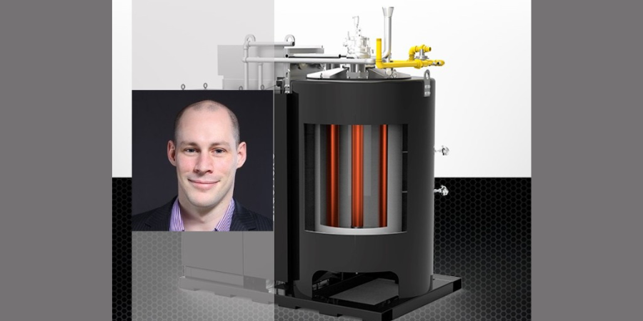
Daniel Panny Product Manager UPC-Marathon in Germany Source: LinkedIn
OWZ Ostalb received a new electrically heated endothermic gas generator. The company wanted to replace the old generator since it had no automatic process control and was unable to control the dew point efficiency in situations where the ambient air changed too much. The old components, which were difficult to replace, further reduced the generator’s overall efficiency.
OWZ Ostalb, a commercial heat treatment company in Aalen, Germany, received the EndoFlex™ S from UPC-Marathon, a Nitrex business unit, in late 2021.
"The customer chose us," says Daniel Panny, product manager at UPC-Marathon in Germany, "because we offered [a] gas mixing and control system, the EndoInjector™, and the [. . .] ReactionCore™ multi-retort system to deliver a reliable, on-demand supply of quality endogas, resulting in significant CO2 savings for their heat-treating operations."
The EndoFlex™ S that was purchased is the electrically heated version with an air cooler, an automatic nitrogen purge system, and additional CH4 monitoring to meet the highest safety standards.
Find heat treating products and services when you search on Heat Treat Buyers Guide.com
What does it mean to "heat treat green"? Between the hype and the cynicism of abilities of "green solutions" to meet climate concerns, there is a robust conversation going on about the real world effects of heat treat technologies and heat treat innovations. In this Technical Tuesday, we'll examine three topics that have been paramount in the discussion over the course of the past year and a half.
If you'd like to read more robust original content from Heat Treat Today, subscribe to the Heat Treat Daily here. Or, if you have a technical article you'd like to share with the North American heat treat industry, contact our editors at editor@heattreattoday.com.
Heat Treating Equipment: Furnaces and Induction Heating
Recently, Solar Atmospheres demonstrated how their new vacuum oil quench furnace is both efficient and safe as well as a "green" alternative to other VOQ methods. Additionally, talk of the greenness of the induction heating process continues to be highly vocalized due to the repeatable and electric method of heating components. Compare these two heat treating equipment technologies below:
Vacuum Oil Quench
"Solar Atmospheres of Western PA announced their newly designed vacuum oil quench furnace (VOQ) has passed startup protocol. There were zero flare and smoke-ups during the quench cycle and the transfer mechanism moved 2000 pound loads with no issues."
Using renewables in the combustion arena of heat treating is a complex topic: real energy used, efficiency, costs, and time to adjust all factor into the discussion. While there still doesn't seem to be one solution to this problem, individuals and companies are drawing lines in the sand to help them make equipment investment decisions for their heat treat operations now.
Overview of the "Renewables" Question
"Using a broad spectrum of green energy sources, likely generated in a decentralized manner, and with regional focus on infrastructure capabilities such as transportation and storage of energy carriers, seems more plausible than focusing purely on an electricity-based energy system."
"But there is really no easy path to replacing the efficiency, both thermodynamic efficiency and economic efficiency, of high temperature heat (flames) — that’s the nature of processing materials. So then, you’re only option is the current affection for “green hydrogen.” This is a profoundly misplaced aspiration."
Water vapor instead of CO2. A huge part of steelmaking is retrieving the pure iron itself in a blast furnace. But this traditional method of getting iron into its usable form requires a lot of heat and a lot of energy. Alternative options that companies are wrestling with are using electric arc furnace (EAF) mills and replacing CO2 with hydrogen. This is a "fringe" conversation to heat treaters, but it is still relevant as downstream manufacturers engineers.
CO2: BOF and EAF Furnaces
"There are a few shifts that need to happen. We must move away from blast furnace steel making. Every product based on that will create huge amounts of CO2. Electric arc furnace (EAF) mills are running the world."
"Around 71 per cent of steel produced today comes from an iron-ore-based method. This typically uses a blast furnace at temperatures of around 1,500°C in which carbon, usually coal, is used to remove oxygen and impurities from the ore to make pig iron. The latter is then turned into steel via a basic oxygen furnace whereby oxygen is blown onto the liquid iron to burn unwanted elements."
"At Cliffs, we don’t want to rely on breakthrough technologies, but rather deal with practical decarbonization options. Our efforts involve the use of the hydrogen contained in natural gas, which is actually a mix of 95% CH4 and 4% C2H6."
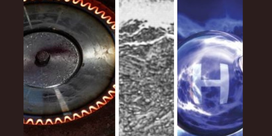
Independence Day is right around the corner, and Heat TreatToday wanted to share some red, white, and blue processes from across the heat treating industry. We're highlighting induction hardening, gas nitriding, and hydrogen generation. Curious? Get ready for Independence Day with this red, white, and blue Technical Tuesday.
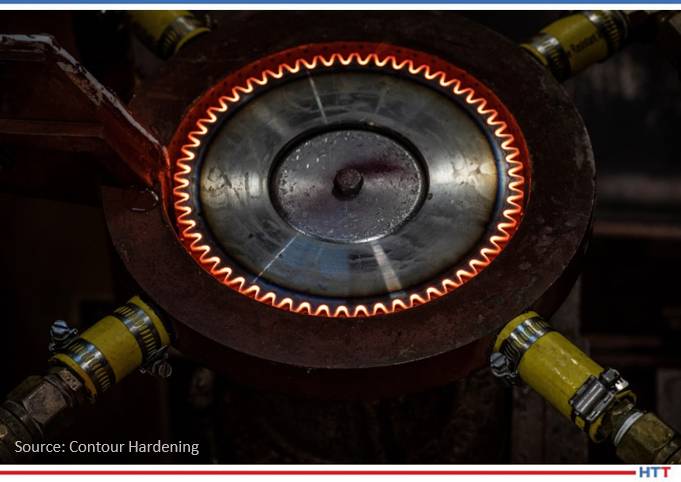
Induction hardening in action Photo Credit: Contour Hardening
Induction hardening is a bit out of place in the heat treating world. There are no huge pieces of equipment, long wait times, or mysterious happenings behind furnace walls. But using those red hot coils for hardening can be a game-changer, because induction hardening offers selective hardening, increased part strength, and uninterrupted process flow.
"The induction coil is a copper conductor that is shaped in order to harden the specified area of the part. The current that flows through the coil is what produces the magnetic field, which in turn heats the part. Coils are typically part specific, since they need to be precisely constructed to heat a particular portion of the part."
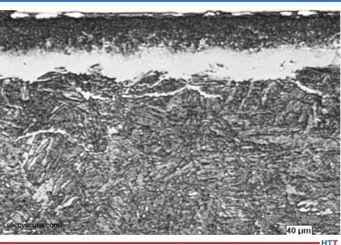
White layer from nitriding Photo Credit: SECO/VACUUM
Gas nitriding is a valuable case hardening process. In gas nitriding, a white layer made up of a nitrogen-rich compound is formed. This white layer is hard and wear-resistant, but is also very brittle.
"This compound layer depth is dependent on processing time. In the more traditional two-stage process, the case depth produces a gradient of hardness from surface to core that commonly ranges from 0.010-0.025”, with minimal white layer, typically between 0-0.0005”."
Water and electricity: that's all the materials that are needed to generate hydrogen on site. Water electrolyzers for hydrogen generation are compact, portable, and reliable, as well as being safer than storing gases. Could the future of heat treating — and perhaps the end of natural gas — be "blue"? Now, unless you live on the beach in the Bahamas, the water you're used to probably isn't blue, but you catch our drift.
"Electricity and water come into a plant in pipes and wires and are highly reliable. Additionally, there are no hydrogen storage tanks taking up a large amount of unusable space."
Find heat treating products and services when you search on Heat Treat Buyers Guide.com
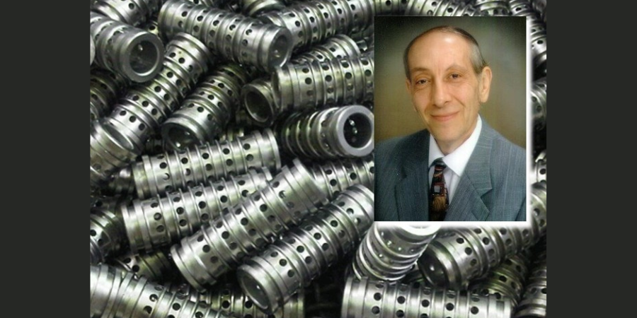
Heat Treat Radiohost, Doug Glenn, and several otherHeat Treat Today team members sit down with long-time industry expert Dan Herring, The Heat Treat Doctor®, to talk about simplified mill practices and processes as they relate to aluminum and steel. Enjoy this second informative Lunch & Learn with theHeat Treat Today team.
Below, you can watch the video, listen to the podcast by clicking on the audio play button, or read an edited transcript.
The following transcript has been edited for your reading enjoyment.
Dan Herring (DH): It’s my pleasure to be here and what I’m going to attempt to do in about the next 30-40 minutes is take about 3 or 4,000 pages of literature and condense it down into some simple English and some common sense, if you will.
We will talk about mill practices, production methods, and what I like to call the forms produced. We might call this whole thing “simplified” for lack of a better terminology, if that makes sense. I’ve selected two very common materials to talk about. The first one is aluminum and the second is steel. But I’m going to disguise that a little bit and talk a little about aluminum and iron. Just to recall, maybe our high school chemistry, aluminum (or aluminium as it’s called by the rest of the world), has chemical symbol Al and iron has chemical symbol Fe. You might wonder how we got Fe from iron: it’s from the Latin word ferrum. Aluminium is another story which I’ll leave for another time, but it is quite interesting.
If we’re going to talk about aluminum and if we’re going to talk about iron, why isn’t steel an element? That’s a question I get very often. Steel is actually an alloy. That’s a combination of different elements. The way I like to think about steel is it’s iron and manganese and carbon and some other alloying elements put in that make specific types of steel that are used for specific applications and application purposes.
Watch or listen to the first episode in this series
The other common question I get is you’ve heard of terms in history like “the stone age” where all the tools and, by the way, the weapons were made of stone. Similarly, the stone age gave way to something called “the bronze age.” That’s where an alloy of copper and tin came on. Again, it made better tools and, by the way, better weapons than the stone tools were. Then, later, you probably heard that there was something called “the iron age”, and we all commonly have heard these terms, but why haven’t we heard about “the steel age”? That’s a common question. What is the steel age? Why isn’t it an age, if you will? That’s because we came up with a very fancy term: The Industrial Revolution, where we started to use steel as an engineering material. I don’t want to get too off subject here, but thought I’d mention that.
So, we begin with raw material, and we call that within the industry an ore. Now, most raw material is in the form of ore or minerals that are found in nature, and they’re typically the element of interest (aluminum or iron in this case) combined with possibly some undesirable elements. The ore that we get from the raw material that we get from the earth has to be refined to make it into a metal. And there are certain raw materials (gold is a good example), that are found in its pure state. I which I could have found more of it in my career, then I wouldn’t be talking to you, but that’s a different story! The idea here is the fact that most ores come in the form of, or most minerals are found in nature and have to be refined.
[blockquote author="Dan Herring, The Heat Treat Doctor®" style="1"][The] chemical bond between aluminum and oxygen is very strong. As a result of that, we need a lot of energy to break that bond apart, to produce aluminum the metal and oxygen the byproduct. A lot of energy is required for that[/blockquote]
The principal ore containing aluminum is something we call bauxite. Bauxite is aluminum oxide, chemical symbol Al203. The way I like to think of bauxite is bauxite is dirt. We can put a dress on it, but it’s still dirt at the end of the day. It’s a special type of dirt. It’s a dirt that has 40-60% aluminum oxide in it. And there are certain areas in the world where bauxite is more common than others. Interestingly enough, Australia is a tremendous source of bauxite as is Africa. That’s why you find the majority of bauxite mines in either Australia or Africa or other places in the world.
When you get into iron, there are two principal ores — there are hematite and magnetite. They are iron oxides and they’re obviously rich in iron.
But to begin, let’s deal with aluminum and what the mill has to do, or what the aluminum manufacturing process really is. We start off, as I said, with dirt, with the raw ore. We then get fancy, and we crush it into a very coarse powder and then after we’ve crushed it, we want to refine it — we want to take and remove some of the impurities. So, we mix it with a little of what we call caustic soda, which is sodium hydroxide, and lime, which is calcium oxide or calcium carbonate, and we use that refining method to purify the raw ore. What we wind up with, interestingly enough, is a very fine white powder which is called alumina or aluminum oxide.
We start out the manufacturing process with a raw material that is a very, very fine powder that is almost all (principally 99%) aluminum oxide. We take it and we put it into a furnace, and we heat it. We do that process with electricity because we’re using carbon anodes, if you will, placed into the bath that we pass current through to melt the aluminum. The process therefore is extremely energy intensive. That’s why you find aluminum production plants in areas like the Tennessee valley, where we have a lot of hydroelectric power. You find them in Iceland, where you have a lot of geothermal energy to help produce electricity. But they’re very electrically intensive operations.
The scientific reason for that is that the chemical bond between aluminum and oxygen is very strong. As a result of that, we need a lot of energy to break that bond apart, to produce aluminum the metal and oxygen the byproduct. A lot of energy is required for that.
You might also find it interesting that when the process was first developed back in the 1880s, and it took that long to produce pure aluminum — if I remember right, the year was 1883 — but the price of an ounce of aluminum was more expensive than the price of an ounce of gold just because of the manufacturing of it.
But anyway, we’ve taken this aluminum powder, which is a white powder, we’ve melted it into a silvery-colored metal, and we do that inside a furnace. Then we tap the furnace — in other words, we pour out the molten aluminum and we either produce cast products from the aluminum or we produce what are called ingots for subsequent working. We either make castings directly or we make ingots.
Cast products, examples of them, might be engine blocks, wheel rims for automobiles, even some small appliances (there are toasters that are cast), patio furniture, tools, cookware — a lot of things wind up just as cast products.
But if we’ve produced an ingot, now we have various methods that we take to produce an engineered product, if you will. We can extrude the aluminum — in other words, we can take an aluminum ingot and we can put it in a press and press it into a form and we can make things like aluminum ladders, bicycle frames, even certain airframe components, out of extruded material. We can take these ingots and we can roll them — we can roll them hot, or we can roll them cold — this is called hot rolling and cold rolling.
But we can turn around and when we roll it, we can make sheet, we can make plate, we can make something that we’re all very familiar with which is aluminum foil. We can make wire, heat exchangers, panels for automobiles, and battery components. Again, in the transportation industry, we can make a lot of things for automobiles or airplanes.
Similarly, we can also forge the material. We hot forge it in this particular case, but we can make various rings and blocks and cylinders and sleeves and components that we can then take and machine.
The process of manufacturing aluminum is relatively straightforward, and it winds up, as I said, with an ingot of some type that is then manufactured into a product.
Doug Glenn (DG): I want to jump in with two thoughts:
You’re talking about that the manufacturing of aluminum from raw materials is highly energy intense. Two points on that: One, it’s much more energy intense than steel production, for one thing, and secondly, that makes some sense of why it is we do so much recycling (or at least try to) of aluminum, because it’s a lot cheaper to take already formed aluminum (an aluminum can or an aluminum wheel off a car) and melt it down. The amount of energy to do that is a lot less than it is to create aluminum from scratch. That was one thing, Dan, if you want to comment on that.
The second thing is you were talking about extruding. I imagine that most everyone knows what that is. You were talking about pressing it into a form. You’ve got to remember that with an extrusion, you’re pressing it through a dye. It’s kind of like your playdough that you push in that form, and you get a shape coming out the other end — that’s extrusion, and not to be confused with forging where you’re putting it into a closed thing and pressing it into a form.
DH: Those are both very, very good comments. Interestingly enough, when you get into iron and steel making, the minerals, the iron oxides if you will, are far easier to break the bond between iron and oxygen than it is between aluminum and oxygen. That’s why the aluminum is such an energy intensive process.
And absolutely correct — recycling saves a tremendous amount of cost and is something that is vital to the long-term success of aluminum because an aluminum product, in general, is more expensive than a steel product.
You are correct — when you extrude something, you basically squeeze it through a dye, if you will. We’ll talk about that a little bit more in forging.
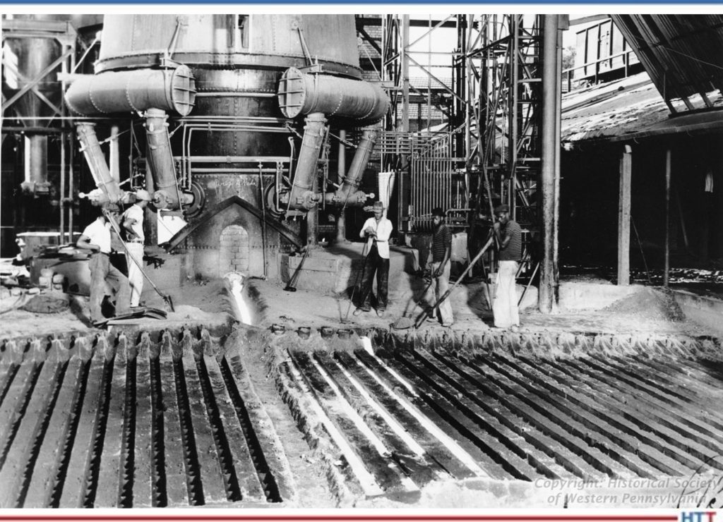
I want everyone to understand that when we start to talk about iron and steel making, because the process has been around for such a long time, there are certain terms that are used in the manufacturing process that have become synonymous with the process itself. Once again, we start out with an iron oxide, a mineral in the form of magnetite or hematite. We take that raw ore and we put it into something called a blast furnace. This is where we do a process called “smelting” of the material. We form a metal by taking and reducing the ore in the presence of air under pressure.
Source: Historic Pittsburgh
Coming out of the blast furnace is molten metal, molten iron, if you will. Now, historically, it’s called “pig iron.” The reason for that is when they originally cast different molds with shapes, the resulting structure looked like a litter of piglets that were actually suckling on their mother. So, the term “pig iron” came about. These little “pigs,” if you will, were broken off from the main casting. As I said, there are a lot of historical things going on.
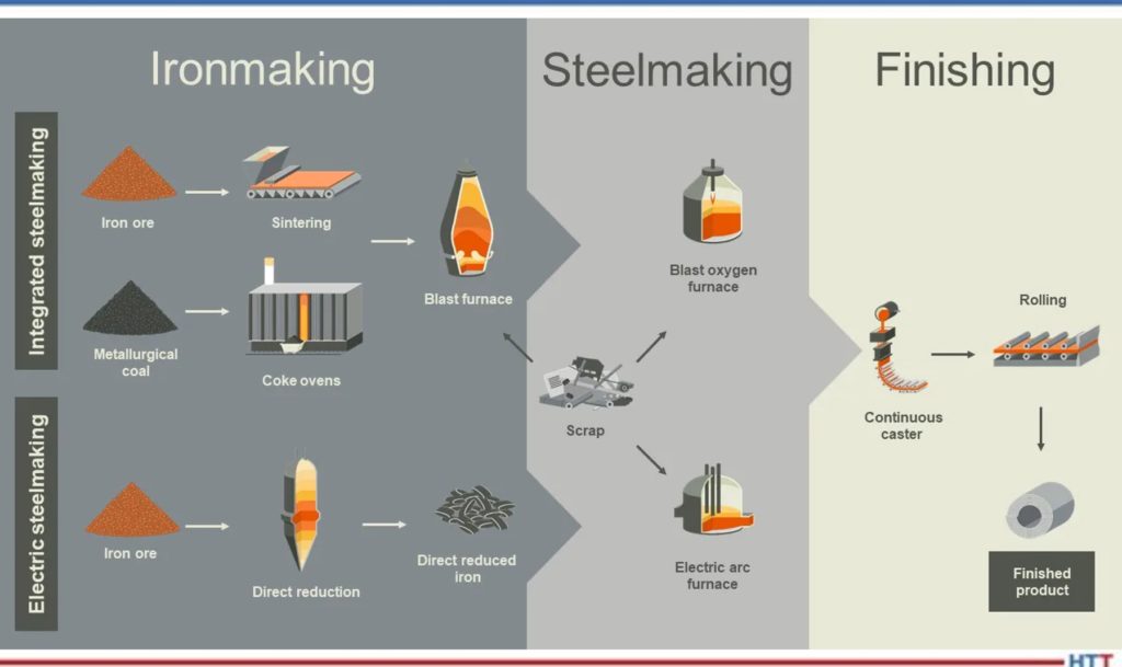
In the old days, you then took the pig iron and you put it into what is called either a BOF (basic oxygen furnace) or an EAF (electric arc furnace) and then you remelted the pigs, if you will. But today, in most of the BOF and EAF processes, you wind up charging a hot liquid iron into those furnaces. They heated up, or continued to heat up, and then you turn around after you’ve converted the pig iron (which is about 94% iron and 6% impurities, so it’s still very impure) and with processing in a BOF or EAF furnace, you get the impurity levels down to less than 1%.
You might say to yourself, “Why is that important?” The idea in steel making is to take the raw material — the iron — and take everything out of it, so we can precisely add back in just those chemical elements that we want to make a particular type of steel. That’s essentially what the BOF or EOF is doing it; it’s converting the molten metal (or the pig iron) into a very, very pure material.
We then do a process which is called “tapping.” We transfer the raw material into a ladle furnace and inside the ladle is where we do the remainder of the refining process. What we wind up doing is we purify the material — we get rid of the additional impurities that are present, anything from hydrogen and oxygen and excess nitrogen to tramp elements and things of this nature. So, in the ladle, we do the refining. This can be done in a vacuum process, a vacuum degassing process, it can be done with an argon process, if you will. But we go from the blast furnace to the refining furnace (the BOF or the EAF), we then go into the ladle and what we’re doing is we’re taking the raw material and we’re making a purer and purer and purer form of, first of all, iron, and then we’re starting to add in elements that we want to make a particular grade of steel or type of steel. Then we’re going to do a process called “teeming” and “casting.” Teeming is basically pouring the molten metal into molds.
Source: BHP
What we wind up with is we have a process where we have liquid steel and we’re going to send it into either something called a continuous caster, we’re going to make ingots out of it, or we’re going to take and atomize the steel. I want to talk about atomizing the liquid steel first. The process is done by adding a gas such as nitrogen or argon or even air, or by using water, but the idea here is that what you wind up with is a powder metal.
By the way, it’s called “powder” metallurgy not “powdered” metallurgy. Powdered is cookies, but powder is what we produce from the atomizing process. The powder can either be spherical in nature or it can be rounded or even irregular-shaped, depending on the type of atomization process. But we take this liquid stream of metal, and we impinge it with either water or gas and burst it or break it apart into particles. Then we do a simple process which is called screening of those particles — it’s basically taking and getting finer and finer, or dividing the powder into finer and finer powders.
Depending on the purification of the powder, how fine the powder is, we use it for what we call conventional powder metallurgy, so we take and use it for basic sintering operations, for example. You’re all familiar with the rearview mirror on your automobile. Interestingly enough, the rearview mirror fits into something called a mirror mount, and that mirror mount is a powder metal part. It happens to be a stainless steel, but it’s a powder metal part.
The idea is the fact that we can have a conventional powder metal. We can have (if we use finer powder) a metal that is suitable for metal injection molding for making things like firearm components, orthodontic braces and things of this nature, or other medical-type devices. Or, if we get a superfine powder, we can turn around and we can use it for something called additive manufacturing.
We’ll talk a little bit more about these later, but from the casting process, we can either go into a continuous caster, we can make ingots, or we can atomize the liquid steel.
If we go into a continuous caster, we’re cooling down the steel and we’re producing three products — they’re called blooms, billets, and bars. Basically, the difference between them is their physical shape. A billet might only be 10 inches square or something of this size (10 x 10 x 10 inches). A bloom is defined as something that is less than one hundred square inches, typically, except if it’s a jumbo bloom caster which makes bigger blooms, but we’ll ignore that as it gets complicated quickly.
The idea here is the fact that we’re either going to take the liquid steel, we’re going to cool it down in some continuous fashion or we’re going to put it into a mold to make an ingot or we’re going to atomize it using water or a gas to make a powder. Those are the three forms that come out of this whole process.
DG: Dan, I’ve got a quick question for you on that: With the aluminum, you mentioned that you can melt it and then cast it directly into a finished product (a cast product). Do we do that much with steel? Do we often take steel and actually take it directly into an alternator casing or some other finished part?
DH: Absolutely. There is a lot of cast steel that is used. The example that comes quickly to mind are probably valve bodies that are used in the petrochemical industry and things. If you think about the iron side, you’re very familiar with cast iron skillets and cast iron cookware. You can also have steel castings as cookware, but you typically don’t as it’s more expensive. But yes, you can make a variety of products directly as a casting.
As I said, you can make powder metallurgy products, and you can also make a family of products that we then call wrought products. What we do is we take those billets, blooms, and bars and then we either hot work them or cold work them to make various types of materials. We can roll them, we can pierce them, we can forge them. We can make sheet, we can make plate, we can make bar and tubular products, we can make wire, we can make strip. A good example is the fact that if you’re a razor blade manufacturer, you want to order material from the mill that’s in the form of strip, thin strip actually.
If, on the other hand, you’re in the oil and gas industry, and if you’re ordering pipe or tubing for use, as we call it, “down hole”, obviously it does no good to have delivered a strip of steel or a sheet of steel or a plate of steel, you want something obviously in the form a tube or a pipe that can then be used.
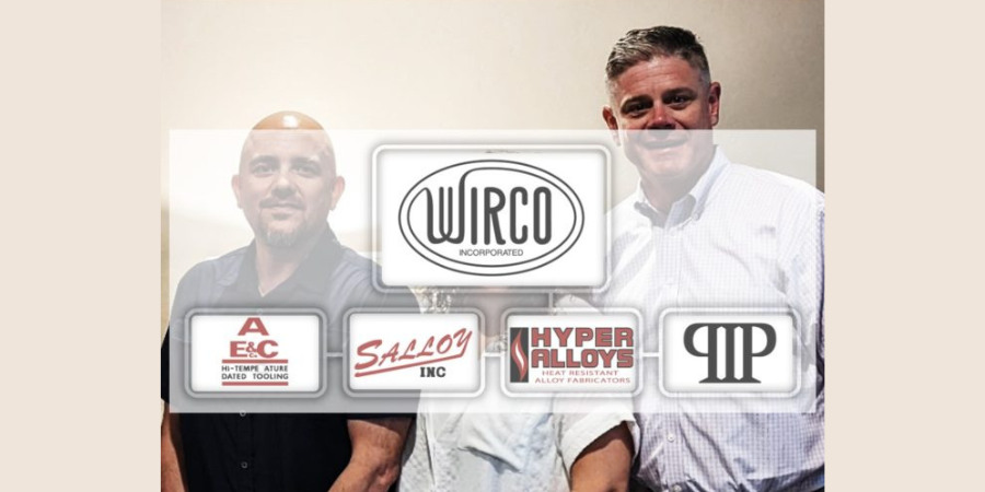
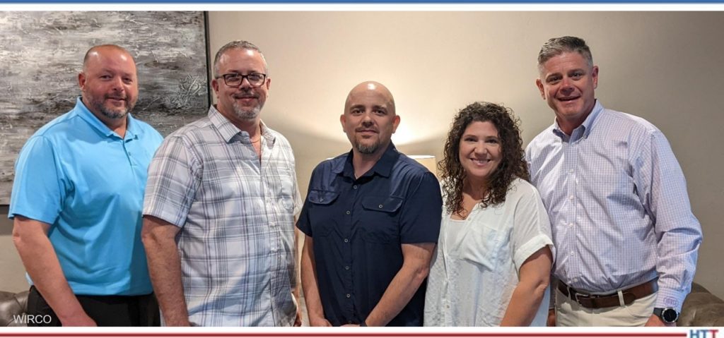
On June 16, 2022, a heat resistant high alloy casting and fabrication company headquartered in Avilla, Indiana acquired certain assets of Performance Industrial Products, LLC (PIP), a dynamic heat resistance high alloy foundry located in Waupaca, Wisconsin.
"We are excited to add PIP’s casting expertise to our American-based centrifugal and no-bake sand casting capabilities," said Chad Wright, president of WIRCO, Inc. "PIP’s expertise and capacity [. . .] greatly increases our ability to supply the growing demand for highly engineered tubular and sand-based castings."
"We are thrilled to be a part of the WIRCO team," added Chris Robbins, president of PIP. He continues that his company looks forward to "We look forward to contributing to their already exceptional reputation in supplying high quality domestic made heat resistant castings and fabrications to the thermal processing industries."
Pictured Above (From Left to Right): Aaron Fisher -Vice President Wirco, Chad Haines – Sales Manager Wirco, Chris and Betsy Robbins PIP, Chad Wright – President Wirco Source: WIRCO
The WIRCO family of companies is headquartered in Avilla, Indiana and is now comprised of three Indiana manufacturing centers along with foundry operations in Champaign, Illinois and Waupaca, Wisconsin.
Find heat treating products and services when you search on Heat Treat Buyers Guide.com
Part discoloration after vacuum heat treating? What can heat treaters do to prevent this? In this best of the web, Q&A-style article, witness the heat treating industry gather around to exchange ideas and find a solution to the problem. Part position, backfill gas level, contaminated quench gas, or an air leak could all be to blame in this Technical Tuesday.
Dan Herring weighs in on the issue as well. To read The Heat Treat Doctor's®diagnosis, click the link below. Learn how the color and position of the discoloration give clues as to the source of the problem.
An excerpt:
"So, what else could be happening? Let The Doctor add a few thoughts to the discussion. First, the fact that the discoloration (staining) is brown in coloration suggests that the oxide is forming on the part surface during cooling when the temperature is in the range of (approximate) 245ºC – 270ºC (475ºF – 520ºF). This is supported by the fact that the oxidation does not occur “during natural cooling” (which we assume to mean cooling under vacuum). Second, the fact that the discoloration is more evident at the bottom of the load suggests the phenomenon is (gas exposure) time dependent, that is, the longer the parts take to cool through the critical range, the greater the chance for discoloration."


 Find heat treating products and services when you search on Heat Treat Buyers Guide.com