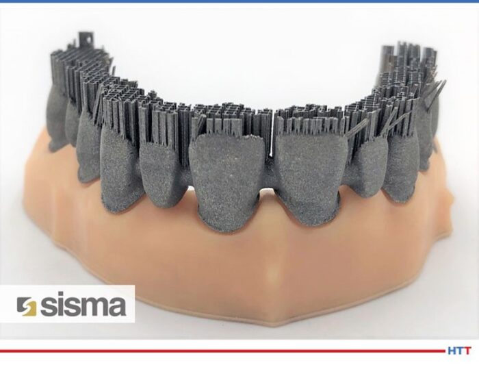
"The global dental 3D printing market is expected to grow significantly over the forecast period... Dental 3D printing is a form of modern dentistry and is considered to be wide-spreading in the dental industry. Dental 3D printing involves creating three dimensional solid dental models such as dentures, surgical guides, dental implants, crown, and bridges." From Market Research Future Report: Dental 3D Printing Market
For this Heat Treat TodayTechnical Tuesday, we are featuring a Best of the Web that highlights cutting edge applications of additive manufacturing (AM). For many in the world of heat treat, AM and 3D are things of the future, oftentimes foreign to the heat treater's processes. What this article reveals is that AM can be utilized in essential and beneficial ways within heat treating.
An excerpt: "...This research and development project managed to optimize the process of making a dental prosthesis using a vacuum furnace. The additive manufacturing allows to create shapes, weights and dimensions customized on different needs and with a precision that has no equal. Strengthened by these peculiarities, the research team worked to further refine and complete the process chain of dental prostheses. Let's see step by step how this process happened."
There is so much to learn in so little time, but if you are at all interested in additive manufacturing (AM), you will want to check out this new study.
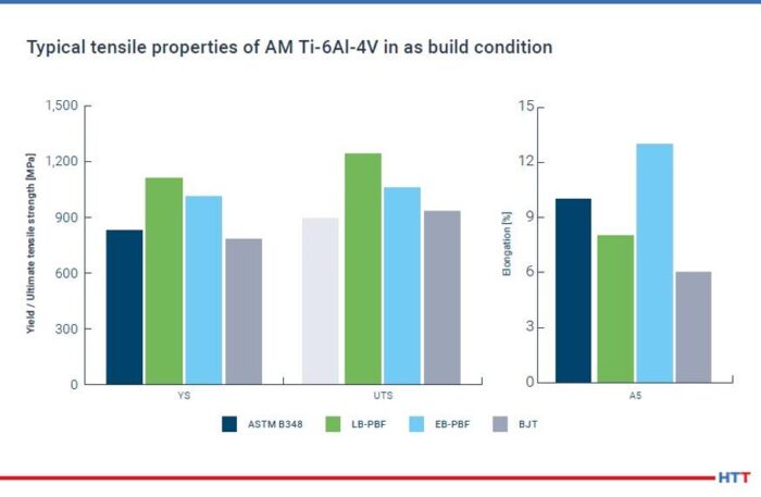
This Heat Treat Today’s Best of the Web feature is full of scholarly findings presented in an easily accessible PDF for free. Three insights that the study elaborates on are: Titanium represents largest share of materials in AM; HIP cycles are not optimized for AM; and part performance may be increased by optimized HIP cycles. The study was developed by Dr.-Ing. Maximilian Munsch, Matthias Schmidt-Lehr, and Dr.-Ing. Eric Wycisk (pictured above in that order).
An excerpt: “To increase the part performance hot isostatic pressing (HIP) is commonly used for highly demanding applications and has become a common post- process for titanium AM parts as well. However, the typically used temperature-pressure-cycles for AM are derived from HIP processes originally used for casting parts.”
Solar Panels (photo source: InterestingEngineering.com)
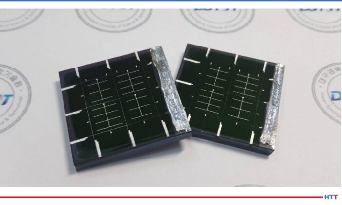
Sometimes our editors find items that are not exactly "heat treat" but do deal with interesting developments in one of our key markets: aerospace, automotive, medical, energy, or general manufacturing. To celebrate getting to the "fringe" of the weekend, Heat Treat Today presents today's Heat Treat Fringe Friday Best of the Web article on efficient alloy-based solar panels. These solar panels are free of toxic metals and can be implemented in producing electronic devices, buildings, and vehicles.
Check out how scientists from Daegu Gyeongbuk Institute of Science and Technology in South Korea were able to overcome issues of underperformance in this article by Interesting Engineering: "Efficient Alloy-Based Solar Panels Created Free of Toxic Metals."
An excerpt: "'Thin-film solar cells using bronze (Cu-Sn) and brass (Cu-Zn) as base materials are composed of non-toxic earth-abundant materials, and have been studied worldwide because of their low cost, high durability, and sustainability,' said Kang[...] While theoretically they are said to perform as well as top market products, in reality, they severely underperform[...] The scientists looked for a way to bypass these flaws and produce the best quality CZTSSe (copper, zinc, tin, sulfur, and selenium) thin films. They came up with the ingenious solution..."
A government military defense organization, located in the southeastern United States, bought a medium-sized high-temperature box furnace for military ceramic composite development. It will also help with research and development for various other components.
The furnace, built by L&L Special Furnace Co., Inc., has a working zone of 24” wide by 18” high by 36” deep and is rated for continuous operating temperatures up to 2500°F (1371°C). It is equipped with silicon carbide heating elements for high temperature operation and sealed from the inside out for use with inert “blanketing gas."
This furnace is controlled by a Honeywellprogram control and corresponding overtemperature protection.
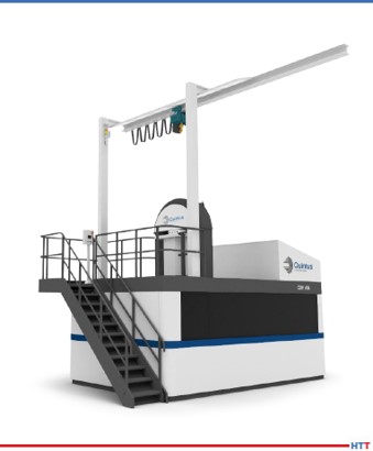
A U.S. manufacturer in high pressure technology has delivered the world’s fastest fan-driven hot isostatic press (HIP) to Italy’s PRES-X, a start-up established to meet the post-production needs of 3D printed metal components. Its industry focus is on aerospace, space, defense, racing, automotive, packaging, and medical device markets.
Additionally, this HIP model is specifically designed for the additive manufacturing (AM) industry. Installation of the press makes PRES-X the first company worldwide to deploy the fan-driven HIP that was designed for this application.
The maker of the fan-driven HIP, Quintus Technologies, notes that the model, QIH 60 M URC®, has capabilities which make it possible to eliminate several operations in the AM production line, and thus create a more cost-effective process. A cooling rate of 1500K/minute can be achieved while minimizing thermal distortion and non-uniform grain growth, producing 3D printed parts with optimal material properties.
Andrea Scanavini CEO and Founder PRES-X (photo source: https://www.tctmagazine.com/)
“Our vision is to become the innovation leader within HIP,” comments Andrea Scanavini, CEO and founder of PRES-X. “The QIH 60’s innovative capabilities have already prompted customers to review their parts production methods, even in application areas that have long used more traditional techniques. This is allowing us to see new project starts and growth in orders and revenue despite a very challenging global market situation.”
Heat treaters have their processes down to a science, literally. But what factor can compromise your heat treated part, let alone possibly cause detrimental damage to your facility?
Greg Steiger Sr. Key Account Manager Idemitsu Lubricants America
Michelle Bennett Quality Assurance Sr. Coordinator Idemitsu Lubricants America
Heat TreatToday is pleased to present this original content article for today's Technical Tuesday. Greg Steiger, senior key account manager at Idemitsu Lubricants America, and Michelle Bennett, quality assurance senior coordinator at Idemitsu Lubricants America, describe water contamination in quench oil, the effects of this contamination, and how to test and safely remove the water from the quench oil.
Introduction
Water is an amazing substance. Water helped create the Grand Canyon and Niagara Falls. When water freezes, it doesn’t contract like most materials. Instead, it expands and creates potholes that swallow up our cars every winter. As the temperature rises, water also expands. This property allows water to heat our homes and is why steam engines work. The thermal expansion of water as it turns into steam is what can create catastrophic events in a quench oil. This paper will look at potential water contamination sources in a quench oil, what the effects of the water can be, how to test for the presence of water in a quench oil, and how to safely remove the water from a quench oil.
Sources of water contamination
There are two major classifications of potential water contamination. The first source can be classified as potential internal sources of water. These potential sources are typically a part of heat treating furnace or oil cooling system. They include water-cooled bearings, fans, doors or heat exchangers. These water-cooled components are under a contestant pressure and will eventually leak. Because the quench tank is usually below these sources of water, the water will eventually find its way into the quench tank. Water-cooled bearings and fans are located within the furnace and are often directly above the quench tank. While a water-cooled door is typically not directly above a quench tank, it is in close proximity to the quench tank. This proximity will allow leaking water to enter the quench tank. Heat exchangers are typically situated away from the furnace. However, in a water-cooled heat exchanger, the water is never more than the wall thickness of the cooling tubes away from the oil. Should a cooling tube form a leak, the water and quench oil would simply mix within the cooling stream and the quench oil water mixture would return to the quench tank.
"The greatest risk of external water contamination lies in preventable operator or maintenance mistakes, especially when the equipment is down and open for maintenance."
The second classification is external sources. These sources of water contamination are not part of the heat treating furnace. Examples of external sources can be further broken down into leaks and operator or maintenance personnel mistakes. Leaks typically include fire extinguishers and fire suppression systems leaks, leaking fire resistant hydraulic systems, atmosphere leaks, pneumatic cylinders and building leaks. To prevent the leak type of contamination, routine maintenance, like a daily “Gemba” walk to spot any leaks, is the best defense against water entering a quench oil through a leak. The greatest risk of external water contamination lies in preventable operator or maintenance mistakes, especially when the equipment is down and open for maintenance.
Quite often when a furnace undergoes repairs, the quench oil is pumped out into empty totes to be reused after the furnace repair is finished. There is nothing wrong with doing this if the totes are clean. However, there have been reports of heat treaters doing this without first inspecting the totes to ensure that they are clean and free of any type of contamination. There have also been instances when the totes were not properly sealed and then stored outside, thus allowing rain water to get into the quench oil. But, the potential to add an incorrect product to the quench tank is a preventable operator error.
How water affects a quench oil
As previously mentioned, water expands as it turns into steam. At 212°F, water has a density of 0.96g/cm3.1 One gallon of water occupies 0.14 ft3. At one degree above boiling the steam from the boiling water has increased to occupy 224 ft3 and a density of 0.0006 g/cm3. The thermal expansion rate of water is approximately 1600%. What this means is the single gallon of water that was in the quench oil before it turned into steam now has a volume approaching 1600 gallons. In order for the 1600 gallons of steam to escape from the quench tank, it must displace an equal amount of quench oil. With nowhere to go, this displaced oil will find hot spots and open flames to create a catastrophic event.
Quench severity
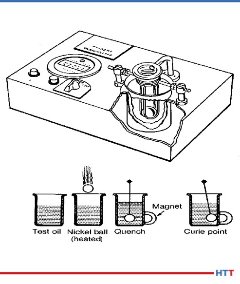
Fig.1 Schematic of ASTM D-3520 (ref. 7)
Historically, the severity of the quench has been measured by ASTM D-35202. In this method, a chromized nickel ball is heated to 885°C and is dropped through an electronic sensor, which starts a timer, and into a steel cylinder of quench oil in a magnetic field. Once the chromized nickel ball reaches the Currie temperature of nickel at 354°C, the ball becomes magnetic and closes the timing circuit when the ball comes into contact with the cylinder. The popularity of this test has always been that it provides a number that is easily interpreted by heat treaters to “rate” the oil as fast (9 – 11 seconds), “medium” (12 – 14 seconds), “slow” (15 – 20 seconds) or marquench (20 - 25 seconds). A schematic of the test method is shown in Figure #1.
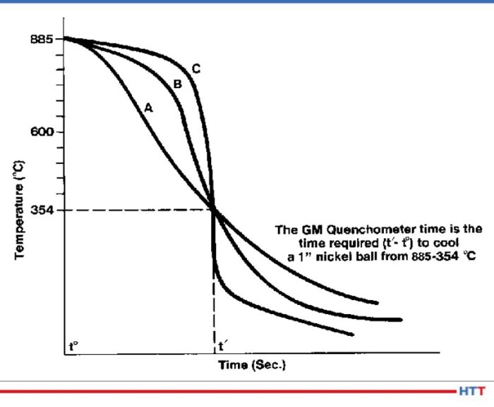
This test worked well to differentiate between different how well the quench oils cooled the nickel ball. The test really didn’t distinguish between the cooling characteristics of a quench oil. The test result in Figure #2show a time in seconds for the nickel ball to reach 354°C for three separate oils. However, when the actual cooling curves of the oils are examined there are three distinct cooling curves shown.
Fig. 2 Three separate cooling curves with the same quench speed as measured by ASTM D-3520 (ref. 7)
Because mechanical properties such as yield strength and hardness are dependent on the severity of the quench, the Grossman H value3 has become more popular over the years. In using the Grossman H value the lower the value the slower and less severe the quench. For instance air has an approximate H value of 0.01 cm-1 and water has an approximate H value of 0.4 cm-1. The calculation used to determine the Grossman H factor has historically been:
Where h is the heat transfer coefficient of the part when measured at the surface of the part and k is the thermal conductivity of the steel. Typically the heat transfer coefficient is measured at 705°C. A steel’s thermal conductivity does not typically change according to alloy composition or temperature. Therefore the Grossman H value is proportional to the heat transfer coefficient of the part.
Cooling curve
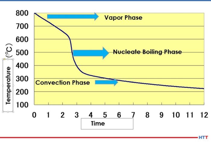
The basic cooling curve consists of three stages: the vapor blanket, nucleate boiling and convection. A basic cooling curve with the three different cooling phases is shown in Figure #3.
Fig.3 Three stage cooling curve (ref. 4)
In the vapor blanket stage, the load and the quench oil coming into contact with the load are above the evaporation temperature of the oil. An insulating vapor blanket forms around the load and no cooling occurs. Because the vapor blanket is insulating and does not allow for cooling, the vapor stage carries the highest risk of distortion.4 Once the vapor pressure decreases to a point where the oil can once again condense on the load and the temperature of the oil falls below the evaporation temperature, the nucleate boiling stage begins. In this stage, the load undergoes the most aggressive cooling. After sufficient cooling has occurred and the quench oil temperature is below the boiling temperature of the oil, a smooth transition into the convection stage begins.
Stabilization of the vapor stage
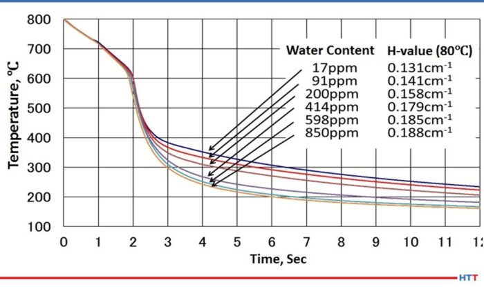
As water is dispersed throughout the oil, the viscosity of the oil changes. As the amount of water increases, the viscosity of the oil also increases.5 A careful examination of Figure #4 will also show a slight movement of the cooling curve to the left and a lengthening of the vapor stage as the amount of water increases. Furthermore the water in the oil is not uniformly dispersed, and this non-uniform dispersion creates uneven cooling rates throughout the oil. To restore even cooling, it is recommended the water in the quench oil be reduced to below 200 PPM.
Fig. 4 Cooling curve change due to water contamination (ref. 4)
Types of water found in a quench oil
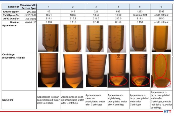
In simplistic terms, water in a quench oil can be thought of as being dispersed in the quench oil due to agitation or as free water having exceeded the saturation point of the oil. As a general rule of thumb in the industry, the saturation point is considered to be 0.1% or 1,000 PPM. However, the saturation point will vary according to the temperature of the oil and the additives within the quench oil. Daphne Hi Temp A-U is a good example of a clear amber quench oil. Figure #5 shows a picture array of the appearance of the oil as the amount of water approaches and then exceeds the 1000 PPM industry standard.
Fig. 5 Daphne Hi Temp A-U appearance as the amount of water dispersed within the oil nears and exceeds the saturation point of the oil. (Used with permission Idemitsu Lubricants America)
Notice in the data above that as the amount of water increases in the Daphne Hi Temp A-U, so does the viscosity as measured at 100°C. In addition to the viscosity rising as the amount of dispersed water increases, so also does the quench severity as measured by the Grossman H value. Furthermore, the appearance of the quench oil changes as the amount of water increases as well. (See Fig. 5 for the Daphne Hi Temp A-U.) With small amounts of dispersed water—45 PPM—the quench oil is clear and there is no water that is precipitated out after centrifuging for 15 minutes at 5500 RPM. However, as the amount of water begins to approach the 1000 PPM level, the appearance of the quench oil begins to become hazy. As the saturation point is exceeded, the appearance remains hazy and water precipitates out after centrifuging for 15 minutes at 5500 RPM.
Testing for oil in a quench oil
There are two basic types of testing methods for determining if there is water dispersed in a quench oil. One of the methods is subjective and the other is quantitative. The crackle test involves heating a metal coupon to approximately 400°F and placing a few drops of the quench oil on the surface. If there is a sufficient amount of water in the oil visible bubbling within the oil and audible crackling will occur. Unfortunately, this is typically above the saturation point of the quench oil. At which point it is often too late. Figure #6 shows examples of crackle testing.
Fig. 6 Crackle test results for Daphne Hi Temp A-U
The second and preferred testing method is through ASTM D-6304 Standard Test Method for Determination of Water in Petroleum Products, Lubricating Oils and Additives by Coulometric Karl Fisher Titration6. The Karl Fisher test uses the Bunsen electrochemical reaction to calculate the amount of water in a used oil and is accurate in used oil from 1 PPM to 50,000 PPM.
Removing water from a quench oil
Removing excessive water from a quench oil can be achieved economically through several methods. Table #1 is a brief trouble shooting guide to the safe removal of water from a quench oil.
Table 1 Trouble shooting guide for removal of water from a quench oil
Conclusion
Finding small amounts of water, less than 50 PPM is very common in a used quench oil sample. This small amount could simply be condensation within the bottle and quench tank. However,when the amount of water begins to reach levels above 200 PPM, troubles can begin. At levels above 200 PPM of water, the following may occur:
Uneven cooling due to non-uniform dispersing of the water within the quench oil
Increase in viscosity
Increase in Grossman H Value
Lengthening of the vapor blanket stage
Increase in the severity of the quench
Like most materials, water expands as it changes from a liquid into a vapor. With a thermal expansion rate of 1600%, a gallon of water turns into considerable more steam. Therefore excessive water transitioning into steam in a quench oil creates safety concerns when the steam forces the quench oil from the tank. Examples of these safety concerns are:
Risk of harm and injury to plant personnel
Damage to furnaces and related equipment
Damage to the heat treat facility the surrounding plant and nearby buildings
Severe cases can result in a quench oil fire or a building fire
The importance of a “Gemba" walk should not be overlooked. Water can enter into quench oil systems through normal heat treating operations such as a leak in a water-cooled piece of equipment, others can be from preventable sources such as a building leak or other human error. No matter what the source is, if water is suspected in a quench oil, the quench tank should be sampled and tested before it is used.
References:
Handbook of Chemistry and Physics. 60th edition CRC Press, p. E-18.
ASTM International, “Standard Test Method for Standard Time of Heat Treating Fluids (Magnetic Quenchometer Method),” American Society for Standards and Materials.
M. A. Grossman and M. Asimov, “Hardenability and Quenching,” 1940, Iron Age Vol. 107 no.17, p. 25-29.
ASTM International, "ASTM D-6304 Standard Test Method for Determination of Water in Petroleum Products, Lubricating Oils and Additives Coulometric Karl Fischer Titration," West Conshohocken, ASTM International, 2016.
B. Lisic and G.E. Totten, "From GM Quenchometer Via Cooling Curve Analysis to Temperature Gradient Method," ASM Proceedings: Heat Treating, 18th Conference, 1998.
About the Authors:
Greg Steiger is the senior key account manager of Idemitsu Lubricants America for quench products. Previous to this position, Steiger served in a variety of technical service, research and development, and sales marketing roles for Chemtool, Inc., Witco Chemical Company, Inc., D.A. Stuart Company, and Safety-Kleen, Inc. He obtained a BSc in Chemistry from the University of Illinois at Chicago and is currently pursuing a Master’s Degree in Materials Engineering at Auburn University. He is also a member of ASM International.
Michelle Bennett is the quality assurance senior coordinator at Idemitsu Lubricants America, supervising the company's I-LAS used oil analysis program. Over the past 9 years, she has worked in the quality control lab and the research and development department. Her bachelor’s degree is in Chemistry from Indiana University.
Heat Treat T0day is happy to announce the winners of the 40 Under 40 Class of 2020! Click here to see the list, or click to access the Q3 digital edition.
North American commercial heat treater installs their sixth all-metal hot zone furnace at their Souderton plant in Eastern PA. This is Solar Atmospheres' sixth all-metal hot zone furnace installation, and the fourth for their climate-controlled room.
The furnace is a new Mentor model, built by sister company Solar Manufacturing, has a working zone of 12” x 12” x 18”, and is the first of its kind. The additional furnace increases the heat treater's capacity for processing sensitive materials such as PH stainless, nickel-based superalloys, titanium, and ferritic/austenitic stainless steels, yet focuses on smaller lots and one-off items. The furnace makes it possible to reap the benefits of an all-metal furnace while minimizing the overall cost.
In this 4-part series, Heat Treat Radio host, Doug Glenn, talks with Joe Powell of Integrated Heat Treating Solutions about bringing heat treating into the 21st century.
According to Joe, the real focus should be on the quenching portion of the process where distortion often happens. In many instances, distortion is able to be eliminated. Find out how in this episode.
Below, you can either listen to the podcast by clicking on the audio play button, or you can read an edited version of the transcript.
The following transcript has been edited for your reading enjoyment.
Doug Glenn (DG): On today’s episode, I sit down with Joe Powell, president of Akron Steel Treating Company to hear what he and his team are doing to combat heat treat distortion. Joe Powell is a veteran in the industry and carries a wealth of knowledge with him. Joe, your company has 75 years of experience working with different part makers, and after a very brief conversation with you, pretty much anyone would conclude that you’re a man on a mission to bring heat treating into the 21st century. Before we turn you loose on that topic, first tell us a little bit about Akron Steel Treating and how it got started.
Joe Powell (JP): It was founded by my father in our garage in 1943 at the behest of the Department of the Army who wanted him to heat treat some parts, and it grew along with all the tool and dye makers in Akron, OH by making machinery for making various rubber products like tires, belts and hoses . . . you name it.
DG: You’ve also spearheaded another company: Integrated Heat Treating Solutions. What are you doing with that company?
It should be “quench treating” not “heat treating.” That’s the way I look at it.
JP: Integrated Heat Treating Solutions is the culmination of 75 years of commercial heat treating experience with literally over a 1000 different part makers. What we’ve learned that if we can integrate our heat treating solutions with the part-making design and the optimal material selection, we can produce better parts. And what I mean by “better parts” is they could be lighter, they could have longer fatigue life, and they could have less distortion after heat treating. All of these benefits are brought to the table to part makers so that heat treating becomes a fully integrated part of lean manufacturing.
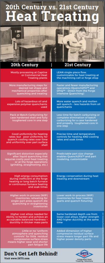
Once heat treating becomes a lean, integrated part of manufacturing, everybody wins. It enables the use of leaner alloy materials; it eliminates oil quenching; it eliminates long carburizing cycles and batch carburizing cycles; and we now are able to literally do the heat treating in the manufacturing cell where the parts are made.
DG: What do those two companies look like now?
JP: We have about 50,000 square feet and are currently in the process of acquiring another building to our east. We have 48 employees and there are three shifts; and again, we do salt heat treatment, vacuum heat treatment and controlled atmosphere heat treatment. Also, we are currently getting into induction heat treating with our friends at Induction Tooling.
For the last 23 years, we have been concentrating on finding the best way to quench parts and to drive the distortion out of the part-making process. The heat treat distortion has been a problem for centuries. Parts crack, they distort, they come out of the heat treat process unpredictably with size change that is absolutely necessary to get the mechanical properties, but also, if it’s nonuniform, that size change can cause major problems down the line that have to be corrected by hard turning, grinding, flattening, straightening, you name it.
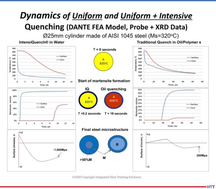
Dynamics of uniform and Uniform Intensive Quenching model (Source: integratedheattreatingsolutions.com)
We’ve also delved into the science of computer modeling, finite element modeling as well as computation of fluid dynamic modeling with our friends at DANTE Solutions. What has happened from that modeling is seeing this concept: the surface of the part contains a bunch of grains, and those finite elements – if they are not quenched uniformly – will transform nonuniform, leading to nonuniform thermal shrinkage upon beginning quenched. Then they will also transform to martensite nonuniformly, which means that the thin and thick sections of a part will have different amounts of distortion and size change. In order to control that, we’ve developed what we call “quench to fit” technologies where we literally build a shell on the outside of the part, using a gas quench or a uniform salt quench or uniform water quench. Once you’ve built that shell in the first few seconds of the quench on the outside of the part, that martensite shell acts like a custom-made quench dye, and that custom-made quench dye allows the part core to cool by conduction through that shell. So, if that cooling by conduction happens by very uniform conduction through the geometry and the mass of a given part, you will have a predictable size change after heat treat. And, you will enable the part designer to go back to the initial part design and adjust it accordingly so that it quenches to fit during the quench process.
When a commercial heat treater receives the part, 99 times out of 100, that part is using a material that was selected many, many years ago, because that is what they’ve always used. Additionally, it’s going to be heat treated in legacy equipment that has always been used. For instance, case carburized 8620 steel valve seats have been used for decades now, and they last about 40-70 hours in the fracking pump, but a ductile iron valve seat can be made to last many times longer; it’s cheaper to buy the material and our heat treating equipment can heat treat it in 5 minutes instead of a 20 hour case carburizing cycle in batches. That single part flow of that new induction heat treating equipment and quenching equipment that is built into it can be built in right at the end of the CNC machines.
I am a commercial heat treater who believes that part design should be integrated for heat treating by the part-maker. It’s a nuance, but what it really boils down to is that sometimes commercial heat treaters do it best, but sometimes the part-maker can do it better. [Side bar quote: I am a commercial heat treater who believes that part design should be integrated for heat treating by the part-maker. It’s a nuance, but what it really boils down to is that sometimes commercial heat treaters do it best, but sometimes the part-maker can do it better.]
I am a commercial heat treater who believes that part design should be integrated for heat treating by the part-maker. It’s a nuance, but what it really boils down to is that sometimes commercial heat treaters do it best, but sometimes the part-maker can do it better.
DG: So, the importance in the part design process of including the heat treater is that you can more consistently predict what the distortion will be, because if I understand it correctly, you can actually predict distortion in the part and therefore design the part with the distortion that will come consistently every time you design that part, yes?
JP: Yes. And it doesn’t matter if it’s an air quench or a hot salt quench or a uniform water quench, it just has to be very, very uniform from the initiation of the quench. In other words, you can’t take it out of the furnace and air cool it for 45 seconds and then begin a water quench, it doesn’t work that way. That shell is starting to form instantaneously when the heat is turned off. An air quench is very slow compared to an intensive water quench and so you have to introduce that quench all over the part surface shell as instantaneously, and with as much uniform impact, as possible. That’s what we do in terms of designing equipment to do the quench process.
DG: Right now, there are a lot of companies, a contractor or commercial heat treater, that send you parts to heat treat. Is it not possible that if the part designer and the heat treater talk in advance as they design the part, that some of these parts could be, in fact, heat treated in-house and not be sent out to a commercial heat treater? Is that possible?
JP: They could actually be heat treated not only in-house, but directly after the CNC machine, right in the manufacturing cell, right after the forge. It takes the proper selection of the optimal hardened ability material. In other words, part of that part design with the heat treater has to be considerations like, “Is it going to get too hard in the core? Is it going to swell up too much in the core? Is it going to be unable to build that shell on the surface without blowing it off, because the core starts to harden up?” So again, the optimal material selection and the design of the mass and the geometry of the part need to be considerations that the heat treater gets a chance to look at.
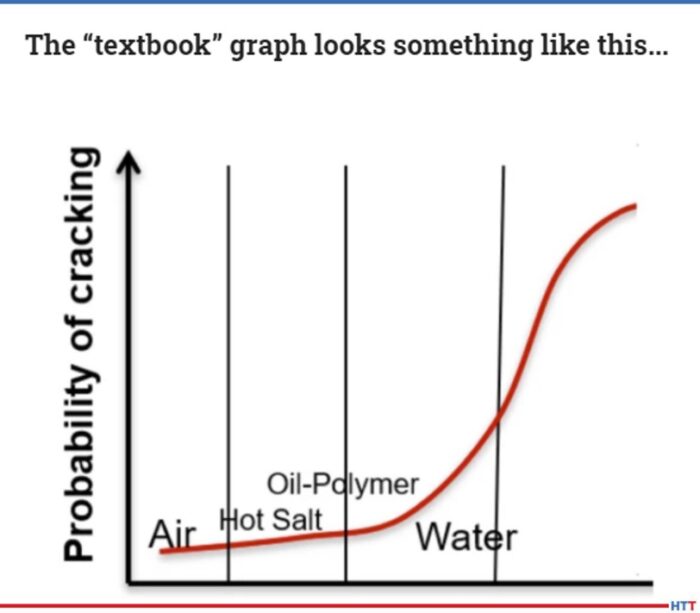
A “textbook” example of the bell curve. (Source: integratedheattreatingsolutions.com)
DG: So, if the part designer and the heat treater get together and talk about the part design before the part is finalized, or if they’ve got a legacy part, they can sit down and talk with a heat treater that understands what you’re doing over at Akron Steel and Integrated Heat Treating Solutions. If they can understand that, and if they can talk with you about how that part might be redesigned, it’s very possible that you could use lower cost materials to get the same thing, minimize the amount of time to actually heat treat, and you may be able to put that part in a single piece or at least possibly a small batch flow so that there’s not a bottleneck at heat treat, yes?
JP: Yes.
Sponsorship for this episode is Furnaces North America the Virtual Show.
DG: Joe, let’s talk about the quenching bell curve as it relates to distortion.
JP: There are many, many metallurgists and many metallurgical textbooks that indicate that the faster the quench cooling rate, the higher the probability of distortion. There is a curve that is generated that basically says that if you quench very slowly in gas, or if you increase that quench rate and go to a hot salt or a martemper bath or an austemper bath or you increase it even further with warm oil or highly agitated oil, or you go to a brine quench where you do a polymer or a polymer water quench where you increase the rate of quench cooling, there is a point at which most of the parts are going to crack and you’re going to have major distortion. It is not because of the quench speed being faster, it is because the uniformity tends to be less the faster your quenchant. In other words, you need to keep the water from film-boiling and creating a situation where the initial quench is actually done under a steam blanket, or gas, very slowly. Once the thin sections of the part quench-out under gas, then you have the thick sections that are still under that gas blanket, and you have very rapid cooling and very rapid martensite transformations that cause a shift in the size of the part where the shell now cannot contain the core swelling that’s happening underneath the surface.
Whereas 21st century heat treating practice is, what I call, a “uniform quench renewal rate” and an instant impact. In other words, you instantly impact the shell, create that shell, and once it’s created with uniform cooling, then the rest of the cooling happens by conduction through that shell. Whatever the geometry and the mass of the part is will determine that uniform conduction cooling which ends up being very predictable. Once it’s predictable, then you can morph the green size of the part before heat treating so that it predictably quenches to fit during the quench process.
(source: integratedheattreatingsolutions.com)
DANTE Solutions has a method where they use their model to model the finite elements in the part so that the thin and thick sections of the part quench uniformly. IQ Technologies Inc. and my company, Integrated Heat Treating Solutions, have gone on the other side and shown that it is really a bell-shaped curve, and that the probability of distortion goes back down if you can create that shell on the outside of the part instantaneously, and then provide a uniform quench renewal rate to the part surface so that the core can cool by uniform conduction through that shell.
DG: Let’s just put in our listener’s minds the standard bell curve. Most of the quenching and most of the textbooks that we see these days is done on the left hand side of that bell curve, and as you approach the peak of that bell curve, the probability of distortion and/or cracking occurs. People are saying – don’t quench too fast because you’ll get cracking. You’re kind of switching the whole paradigm to say that it’s not the speed at which you quench, but more so: Can you create, almost instantaneously, a hard shell because of exceptionally rapid cooling on the whole part so that that shell basically holds the part in place? If you can get that, then you can cool the rest of the part, however slow or fast, in a sense, you want, because it’s not going to distort because it’s already locked in.
JP: Right, and this is cooling by conduction which is the physics of the material. How fast will it give up the heat through its mass? It’s the difference between 100 degrees or 50 degrees or 10 degrees per second of cooling and 400 to 600 degrees centigrade cooling per second, so it’s very, very intensive. The middle of the bell curve, where most parts are cracking, is because there is not a uniform quench renewal rate. You start off with a gas quench, then you end up with a very intensive evaporative cooling quench with nucleate boiling. You then end up with water quenching without boiling, and so you have three different phases of cooling happening on different parts of the part. This is exacerbated by different parts in different sections of the batch which will have different cooling rates.
It’s almost impossible to get the full benefits of very, very intensive quenching or even very, very uniform gas quenching in a vacuum furnace unless you have staged the cooling in such a way that you create that uniform shell at the beginning of the quench, and you hit that martensite start temperature and cool to that martensite start temperature all over the shell of the part uniformly. That’s the key.
DG: There are several things that jump into my mind like questions that might arise from people. You’ve already hit on the differences in part thickness – you may have thick sections, you may have thin sections. It’s very possible to maybe get down to the martensite start temperature on the thin section right away, but the thick section may not be, and therefore you’re going to distort because you haven’t created that “frozen shell” uniformly around the entire part. Let’s talk about, not just part thickness, but part geometry in the sense of the awkward curves and turns or lips and things of that sort on parts. How would we deal with that?
JP: That’s where new 21st century heat treating equipment needs to be designed. Every furnace company that is selling furnaces to either captive heat treaters or commercial heat treaters calls itself a furnace company. The reality is, yes, heating is important and it is the precursor to getting the mechanical properties, but the heat treatment is actually done, and the mechanical properties are actually obtained, in the quenching process. It should be “quench treating” not “heat treating.” That’s the way I look at it.
Image from Smarter Everyday YoutTube video on Prince Rupert’s Drop (source: https://www.youtube.com/watch?v=xe-f4gokRBs&ab_channel=SmarterEveryDay)
For the last 23 years that’s what has been more apparent to me. My dad taught me how to quench stamps that were used for marking the inside of tire molds, and these steel stamps would uniformly blow up if you just quenched them. But if you were able to uniformly quench the marking end, you could get it hard as hell and it would last a long, long time, but you had to kind of bifurcate the quench. You had to make sure that you created that shell in the marking area of the stamp and let the rest of the stamp kind of cool much more slowly. In other words, create the shell in the face of the stamp where the lettering is, and set those letters. Then the rest of the stamp can basically cool much slower because you don’t need the hardness there; it’s not the working part of the part.
Also, the designers of the stamps had to integrate the right radius in the face of the stamp. If they had sharp corners, those sharp corners would blow off during the heat treat. So, over time, we said, “If you don’t want us to crack this stamp, you’re going to have to put a radius over here and change the design slightly.” It didn’t take much change, but it did take a recognition of the fact that this was not going to work. There’s no way to eliminate the nonuniform cooling in the shell if you’ve got a corner. Steam collects in that corner and it doesn’t quench, so you can’t create the hardened shell.
DG: Let’s take a little deviation and talk about something non-metal. Let’s talk about the Prince Rupert’s drop to illustrate residual compressive stresses.
JP: The mystery of the Prince Rupert’s drop of glass is that glass makers noticed that if they dropped a drop of molten glass into a bucket of cold water it would form a drop that has a head and then a tail – it almost looks like a tadpole. If you hit the head of that glass drop with a hammer or try to break it with a pair of pliers, you can’t do it. It is literally unbreakable at the head. However, if you snap the tail off, it instantaneously explodes. This is because there are counterbalancing tensile stresses that are below the surface in the tail that once you break the compressive stresses off, it’s like taking the hoop off a barrel and the barrel staves explode; the elements on the surface just explode. The reason they don’t explode on the drop of glass at the other end is because there are sufficiently high compressive stresses on that surface that hold the drop of glass and keep it from fracturing.
DG: This is a fascinating video where you take a Prince Rupert’s drop, actually hang this Prince Rupert’s drop and shoot it with a .38 or a .45 or a 9 mm, hitting the head of that tadpole, if you will, and it shatters the bullet while the glass remains untouched. However, if a guy just simply takes his finger, or whatever, and snaps the tail, not just the tail shatters, but the whole tadpole blows up.
JP: What we’ve been able to do with all of the research that we’ve done is to harness those compressive stresses and make them available to the part-marker for making their parts more robust, making them lighter, and making them basically carbide hard and hammer tough. They don’t chip when hit with a hammer.
DG: Let’s jump back to some of the projects you’ve done at Integrated Heat Treating Solutions. Do you have any current projects that you’re working on where this integrated solution – where you were involved with part design or improvement of part design – worked well?
JP: Yes. There are several case studies. The first case study was a punch that lasts 2 – 9 times longer than an oil quench punch.
DG: A punch for what?
JP: Punching holes in metal plates. And the other thing that has happened is that since we’ve begun working with Induction Tooling, we’re able to then bring this down to the level of thinner parts and more complex geometry parts. We’re able to get more hardenability out of lean hardenability alloy such as ductile iron. Plain ductile irons are now acting as carbides. Even the people that make the material said it couldn’t be done, but we’re doing it.
DG: Can you give an example of that?
Watch more resources at Integrated Solutions website. Click the image above to access these resources.
JP: Yes, that would be a fracking pump valve seat made out of ductile iron and heat treated with our special heating and quenching technologies.
DG: What was the performance prior to the treatment and afterwards?
JP: 40 to 60 hours and our initial testing we got 166 hours, so 2 ½ times longer.
DG: So 2 ½ times better performance on this fracking valve seat, and you were using the same material?
JP: No. Rather, we replaced an 8620 carburized steel that needed to be carburized for 20 hours in the furnace, and we did it with a 5 minute induction heating process.
DG: Of what type of material?
JP: Ductile iron.
DG: So we’ve got a punch, a valve seat in the fracking industry. What else?
JP: We have bevel gears that we do. We have worked with the part manufacturer and they’ve adjusted their CNC program so that it actually quenches to fit and doesn’t require a final grind.
DG: Expensive hard machining or hard grinding after heat treat.
JP: Right. And it saves them about $750 per gear in final grind costs. And, the gear lasts longer because it has high residual compressive surface stresses versus a standard carburization process and quenching in oil that does not have as high of a residual compressive surface stress. Especially after you grind it all off to get the final dimensions you want.
DG: Right. So you put all these nice hard stresses in, then you grind them off.
JP: Exactly.
DG: Any other examples?
JP: We have a company that wanted to have a weldable gear rack that could be welded on in the field on mining equipment that’s out on the side of a mountain. Because it might be cold up there, and they didn’t want to have to pre- and post-heat in order to weld on the gear rack, or repair a tooth on the gear rack, they wanted to have a material that had less hardenability but still wanted to have all of the mechanical properties. We were able to get the mechanical properties of 4330 from a 4130 material that doesn’t need to be pre- and post-heated to prevent it from cracking when welding it onto the machinery. They call that “field repairability.” So, we were able to enable field repairability and still maintain the mechanical properties’ requirements.
DG: In future episodes, we’ll go into some depth on some of those applications you just described, but before we wrap up things for this episode, is there a last impression you’d like to leave with us?
JP: Professor Jack Wallace* did not believe that there was a right half of the bell-curve, he did not believe that intensive quenching would work, but, again, he became a believer. It is all key to understanding the dynamics and uniformity of quenching over time. If you get the uniformity, you’re in good shape and eliminate a lot of heat treating problems.
DG: Thanks, Joe. Looking forward to you joining us for future episodes.
JP: Thanks so much.
*Professor Jack Wallace was the “Dean of the College of Metallurgical Engineering at Case Western Reserve University in Cleveland Ohio – who said in 1997, ‘Intensive water quenching would not work! – The parts will blow up in the quench!’ He became a convert once he figured out how compressive surface stresses worked during uniform quenching.” Information provided by Joe Powell.
Doug Glenn, Heat Treat Today publisher and Heat Treat Radio host.
To find other Heat Treat Radio episodes, go to www.heattreattoday.com/radio and look in the list of Heat Treat Radio episodes listed.
We see the expansion plans of companies related to the heat treat industry, and we are with you: How? Why? At this time?
Heat Treat Today’s Original Content article seeks to illuminate some of these questions and frame industry expansion in real terms, as well as share reasons to be hopeful for the future. Featured in this article are Industrial Heating Equipment Association (IHEA) Economic Specialist Dr. Chris Kuehl, Managing Director at Armanda Corporate Intelligence, and Jason Orosz, President of Nitrex Heat Treating Services (HTS).
“COVID-19 may own the spotlight today, but manufacturing’s tomorrow is getting some big-dollar investments.“
It is safe to say that manufacturers have taken encouragement from news of industry giants in the manufacturing industry announcing the status of their expansion plans. Last month, Industry Week covered several of these changes: Navistar International Corp. broke ground for a plant in San Antonio, TX; Canpack Group, based in Krakow, Poland, will build an aluminum beverage can plant in Pennsylvania; Tesla had already begun its Gigafactory located near Austin, Texas which is set to be operational by the end of 2021; and Nikola Corp. also broke ground on its 1 million-square-foot manufacturing facility in Coolidge, Arizona.
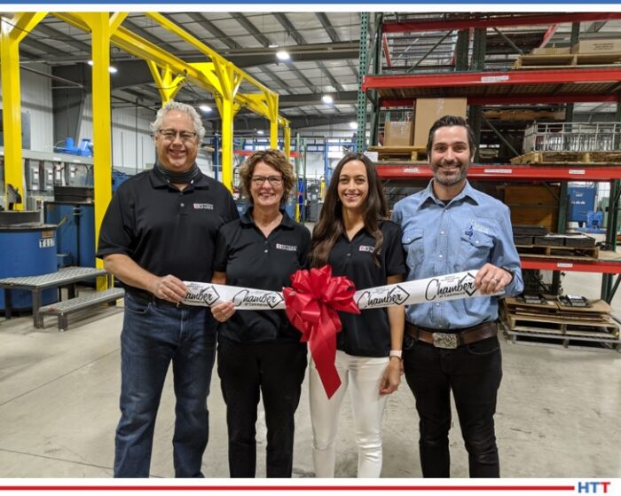
Ribbon Cutting with the Owners: Doug and Jackie Peters, Diana Wilkosz (VP), and Andy Wilkosz (President) (photo source: Peters’ Heat Treating, Inc.)
In the heat treat world, we’ve seen companies, like Peters’ Heat Treating and Nitrex, celebrating plant expansions, opening new facilities and breaking ground to expand existing ones. Jason Orosz, president of Nitrex Heat Treating Services (HTS), illuminates that there is a backstory to the titillating headlines: “[many] recently announced expansion plans… were being formulated well before COVID-19 hit, and are based on assumptions about future business levels for 2021, 2022, 2023, and so on.” He goes on to recognize that, “for many industries, this year’s contraction will be seen as more of a temporary, but severe, loss of business than a permanent reduction.”
Still, what does this trend of expansion in the automotive industry in North America mean?
Dr. Chris Kuehl IHEA Correspondent Managing Director at Armanda Corporate Intelligence
Dr. Chris Kuehl, managing director at Armada Corporate Intelligence and IHEA’s executive economic summaries author, indicates that one must consider existing circumstances before one can understand the transition. For instance, setting up production sites abroad, Kuehl notes, typically has lower production costs, more than simply lower wages. In certain locations, one does not adhere to the same magnitude of regulations and restrictions that are implemented in the U.S. Additionally, access to raw materials is priority, and “setting up shop” closer to those foreign resources has helped to diminish production costs in the past. Lastly, Kuehl points out that thoughtful location of production centers abroad can open up new market opportunities for companies.
Looking at the current rise in production centers in the U.S. may mean three things, says Kuehl. First, the role of technology in capital distribution: “Technology and robotics [have] reduced the importance of cheap labor. The company using machines can worry about other factors. Now, they can think more about transportation costs and access to their market.”
Second, “working overseas is harder now than it was,” Kuehl comments. In previous years, more countries have engaged in protectionism, and the trade wars of last year did not make life any easier. Now, COVID-19 is just another blow to international supply chains, having “stranded some 40% of global cargo and basically crushed the whole concept of JIT [just-in-time production system].”
Jason Orosz President Nitrex Heat Treating Services
This current disruption in the economy cannot be minimized. Orosz states that the current economic climate has impacted how capital is deployed, and can occur in construction being delayed, or perhaps firms holding their cash for any future, COVID-19-related disturbances.
And third: the new trend of “mass customization.” Instead of needing mass quantities of products being made cheaply — which drove the practice of “distance sourcing” — Kuehl highlights that the present “consumer wants infinite variety and specialization,” which, as it were “requires manufacturers be close to that market to understand what is needed and when.”
This trend of bringing supply-chains closer to home is cause for hope, though. “[I] think companies,” comments Orosz, “are optimistic that, going forward, an increasing portion of the supply chain for American multinationals will be U.S.-based vs. what may have been seen over the past few decades. If this trend proves true, it will certainly trickle down into the local industrial heating sector.”
[blockquote author=”Jason Orosz, President of Nitrex Heat Treating Systems” style=”1″]”Over the long term, expansion plans for stable, forward thinking manufacturing companies will proceed mostly unchanged. Of course, there are notable exceptions… but I think situations like that are the exception, not the rule.”[/blockquote]
From left to right : Groundbreaking with Tom Cooper (Vice President of Business Development), Bill Walter (Facility Manager), and Raja Gumber (Senior Account Manager)
Considering present events, Orosz notes that “over the long term, expansion plans for stable, forward thinking manufacturing companies will proceed mostly unchanged. Of course, there are notable exceptions like the passenger aerospace industry whose supply chain will be impacted for a number of years, but I think situations like that are the exception, not the rule.”
“Our expansion in Aurora is on track,” Orosz continues, as an anecdote to his point, “and we expect it to be operational mid-2021. Our main goals are to increase our overall production capacity and install the latest in new technology to ensure that the services we can offer our customers are on the leading edge of what’s possible metallurgically.”
Hope is the often idealized maxim of many societies: “Hope is the thing with feathers,” “we hope in the things unseen,” “our greatest glory is not in never falling, but in rising every time we fall.” But in times of crisis, how many of us choose to do the hard and essential thing: hope?


 Source: TAV, the Vacuum Furnaces Blog