The Heat Treat Doctor® has returned to offer sage advice to Heat Treat Today readers and to answer your questions about heat treating, brazing, sintering, and other types of thermal treatments as well as questions on metallurgy, equipment, and process-related issues.
This informative piece was first released in Heat Treat Today’sFebruary 2025 Air/Atmosphere Furnace Systems print edition.
People often ask two fundamental questions related to normalizing. First, is it necessary? Second, just what and how important is a “still air” cool to the end result? Let’s learn more.
Why Normalize?
Contact us with your Reader Feedback!
Normalizing is typically performed for one or more of the following reasons:
To improve machinability
To improve dimensional stability
To produce a homogeneous microstructure
To reduce banding
To improve ductility
To modify and/or refine the grain structure
To provide a more consistent response when hardening or case hardening
For example, many gear blanks are normalized prior to machining so that during subsequent hardening or case hardening dimensional changes such as growth, shrinkage, or warpage will be better controlled.
Normalizing imparts hardness and strength to both cast iron and steel components. In addition, normalizing helps reduce internal stresses induced by such operations as forging, casting, machining, forming or welding. Normalizing also improves chemical non-homogeneity, improves response to heat treatment (e.g., hardening), and enhances dimensional stability by imparting into the component part a “thermal memory” for subsequent lower temperature processes. Parts that require maximum toughness and those subjected to impact are often normalized. When large cross sections are normalized, they are also tempered to further reduce stress and more closely control mechanical properties.
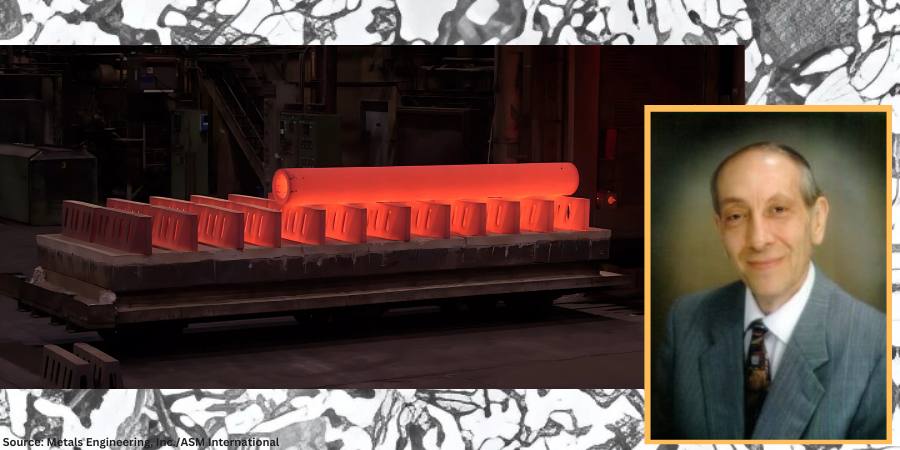
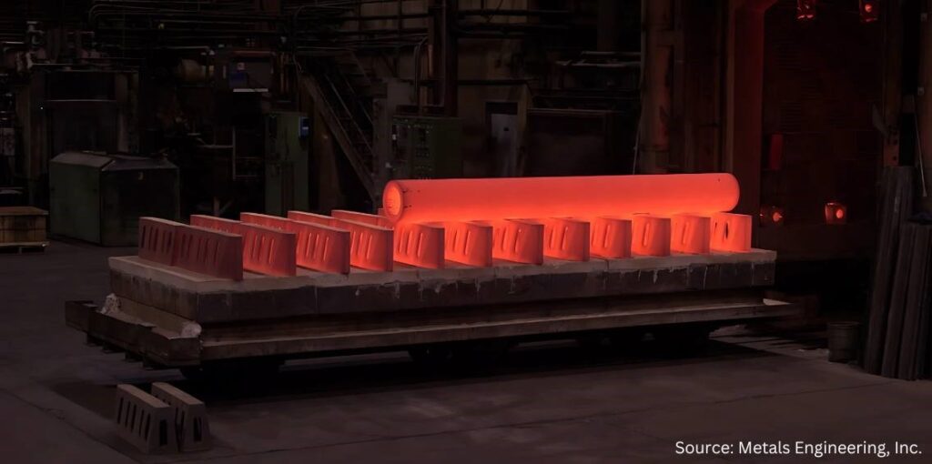
Large paper roll normalized in a car bottom furnace and cooled (due to its mass) using the assistance of a floor fan.
Soak periods for normalizing are typically one hour per inch of cross-sectional area but not less than two hours at temperature. It is important to remember that the mass of the part or the workload can have a significant influence on the cooling rate and thus on the final microstructure. Thin pieces cool faster and are harder after normalizing than thicker ones. By contrast, after furnace cooling in an annealing process, the hardness of the thin and thicker sections is usually about the same.
Micrograph of medium-carbon AISI/SAE 1040 steel showing ferrite grains (white etching constituent) and pearlite (dark etching constituent). Etched in 4% picral followed by 2% nital. (Bramfitt and Benscoter, 2002, p. 4. Reprinted with permission of ASM International. All rights reserved.)
When people think of normalizing, they often relate it to a microstructure consisting primarily of pearlite and ferrite. However, normalized microstructures can vary and combinations of ferrite, pearlite, bainite, and even martensite for a given alloy grade are not uncommon. The resultant microstructure depends on a multitude of factors including, but not limited to, material composition, part geometry, part section size, part mass, and cooling rate (affected by multiple factors). It is important to remember that the microstructure achieved by any given process sequence may or may not be desirable depending on the design and function of the component part.
The microstructures produced by normalizing can be predicted using appropriate continuous cooling transformation diagrams and this will be the subject of a subsequent “Ask The Heat Treat Doctor” column.
In this writer’s eyes, industry best practice would be to specify the desired microstructure, hardness, and mechanical properties resulting from the normalizing operation. Process parameters can then be established, and testing performed (initially and over time) to confirm/verify results.
In many cases, the failure of the normalizing process to achieve the desired outcome centers around the lack of specificity (e.g., engineering drawing requirements, metallurgical and mechanical property call outs, testing/verification practices, and quality assurance measures). Failure to specify the required microstructure and mechanical properties/characteristics can lead to assumptions on the part of the heat treater, which may or may not influence the end result.
“Normalizing is the heat treatment that is produced by austenitizing and air cooling, to produce uniform, fine ferrite/pearlite microstructures in steel … In light sections, especially in alloy hardenable steels, air cooling may be rapid enough to form bainite or martensite instead of ferrite and pearlite.”
What Is Normalizing?
The normalizing process is often characterized in the following way: “Properly normalized parts follow several simple guidelines, which include heating uniformly to temperature and to a temperature high enough to ensure complete transformation to austenite; soaking at austenitizing temperature long enough to achieve uniform temperature throughout the part mass; and cooling in a uniform manner, typically in still air” (Herring, 2014).
It is also important to remember that normalizing is a long-established heat treatment practice. As far back as 1935, Grossmann and Bain wrote:
Normalizing is the name applied to a heat treatment in which the steel is heated above its critical range (that is, heated to make it wholly austenitic) and is then allowed to cool in air.
Since this is one specific form of heat treatment, it will be realized that the structure and mechanical properties resulting from the normalizing treatment will depend not only on the precise composition of the steel but also on the precise way in which the cooling is carried out.
The term ‘normalizing’ is generally applied to any cooling ‘in air.’ But in reality, this may cover a wide range of cooling conditions, from a single small bar cooled in air (which is fairly rapid cooling) to that of a large number of forgings piled together on a forge shop floor … which is a rather slow cool, approaching an anneal. The resulting properties in the two cases are quite different.
In plain carbon steels and in steel having a small alloy content, the air-cooled (normalized) structure is usually pearlite and ferrite or pearlite alone … More rapid cooling gives fine pearlite, which is harder; slow cooling gives coarse pearlite, which is soft. In some few alloy steels, the normalized structure in part may be bainite.
The hardness of normalized steels will usually range from about 150 to 350 Brinell (10 to 35 Rockwell C), depending on the size of the piece, its composition and hardening characteristics.
Importance of Defining Cooling Rate
In 2005, Krauss underscored the importance of defining cooling rate when he wrote: “Air cooling associated with normalizing produces a range of cooling rates depending on section size [and to some extent, load mass]. Heavier sections [and large loads] air cool at much lower cooling rates than do light sections because of the added time required for thermal conductivity to lower temperatures of central portions of the workpiece.”
Microstructures Created by Normalizing
The microstructural constituents produced by normalizing for a particular steel grade can be ferrite, pearlite, bainite, or martensite. The desired microstructure from normalizing adds an important cautionary note, as addressed by Krauss in STEELS (1990 and 2005), namely: “Normalizing is the heat treatment that is produced by austenitizing and air cooling, to produce uniform, fine ferrite/pearlite microstructures in steel … In light sections, especially in alloy hardenable steels, air cooling may be rapid enough to form bainite or martensite instead of ferrite and pearlite.”
Next time: We define a “still air” cool and look at the state of normalizing in North America.
Practical Data for Metallurgists, 17th ed. TimkenSteel.
Totten, George E., ed. Steel Heat Treatment Handbook, vol. 2, 2nd ed., CRC Press, 2007. 612-613.
About the Author
Dan Herring “The Heat Treat Doctor” The HERRING GROUP, Inc.
Dan Herring has been in the industry for over 50 years and has gained vast experience in fields that include materials science, engineering, metallurgy, new product research, and many other areas. He is the author of six books and over 700 technical articles.
In this Heat TreatRadioepisode, Mark Rhoa, Jr. from Chiz Bros, a company specializing in ceramic fiber products, discusses insulation with host Doug Glenn. Mark focuses on the benefits of ceramic fiber in industrial applications. The conversation covers decarbonization, the importance of insulation and thermal shock resistance, the shift to electrically heated modules, and practical maintenance tips for ceramic fiber-insulated furnaces.
Below, you can watch the video, listen to the podcast by clicking on the audio play button, or read an edited transcript.
Doug Glenn:I want to welcome our guest today: Mark Rhoa Jr. from Elizabeth, Pennsylvania, near Pittsburgh. Mark’s been involved with the industry for quite a while with Chiz Bros, our sponsor for today. Mark is also aHeat TreatToday40 Under 40honoree from the Class of 2021. And, Mark, could you tell me who started your company — your dad or your dad and his brother? I don’t know the history that well.
Mark Rhoa: My dad actually joined the company in ‘97, but when he joined, Chiz Bros. had been around for a good 30 years or so. It was started by the Chiz brothers originally: Al, Ray, and John Chiz. As they got older and some of them moved on from the company to retire, my dad took over the company in 2014, and that’s when I came on board.
I’ve been here about ten years. And Ray Chiz Jr. just recently retired; he is one of the original owners’ sons who was working here running our warehouse. He’s the last with the Chiz name to work here. We say that the Chiz haircut is kind of what I’ve got going on. You can know by the haircut there’s a lot of Chiz’s still working here, and you might even be an honorary.
Doug Glenn: I can be an honorary, for sure. I don’t have enough on the side.
Chiz has been around for 50 some years doing specialty solutions for refractory applications in the metals, power, glass, and ceramics industries. And you guys deal with multinational companies as well as the small Ma and Pa shop furnace manufacturers or heat treaters/thermal processors, a pretty good mix. You’ve got great customer service, reasonable pricing, and quick delivery. And I know you and I have talked about how you guys pride yourselves on having a lot of stuff in stock. And finally, you guys have your Pittsburgh location and are also in Detroit, which is a relatively new addition, right?
Mark Rhoa: Yeah, about two years ago we opened up a Detroit warehouse. We’ve always had some good clients up that way. You’ve got to have some boots on the ground to be super effective. I say to get the easy orders you’ve got to have the stuff on the ground to get the hard orders, which are the phone calls at 5 o’clock on a Friday saying, “Hey, we need to pick this up because the furnace is down.” And we didn’t have that opportunity to improve our customer service up there before opening that location.
We try to punch above our weight to compete with the big guys on pricing. We make sure we’re always still answering the phone.
Doug Glenn: It makes a huge difference when you’ve actually got people answering the phone.
My understanding is that you provide castables, fibers, brick, etc. But today we want to hone in a little bit on ceramic fiber.
Mark Rhoa: Ceramic fiber is the big portion of our business. We’re one of the biggest Unifrax (Alkegen) ceramic fiber distributors in the country. So, a lot of what we do is being driven by ceramic fiber products we supply. We still can supply castables, bricks, and everything in between. But ceramic fiber drives the ship for us.
What Is Ceramic Fiber? (04:58)
Doug Glenn: Let’s talk about that. Most of our listeners are folks with their own in-house heat treat. But let’s assume we’ve got some people watching that don’t know some basics.
Tell us about ceramic fiber: What is it? How is it made? What are we using it for?
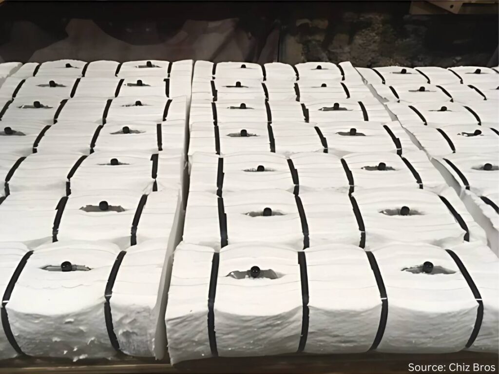
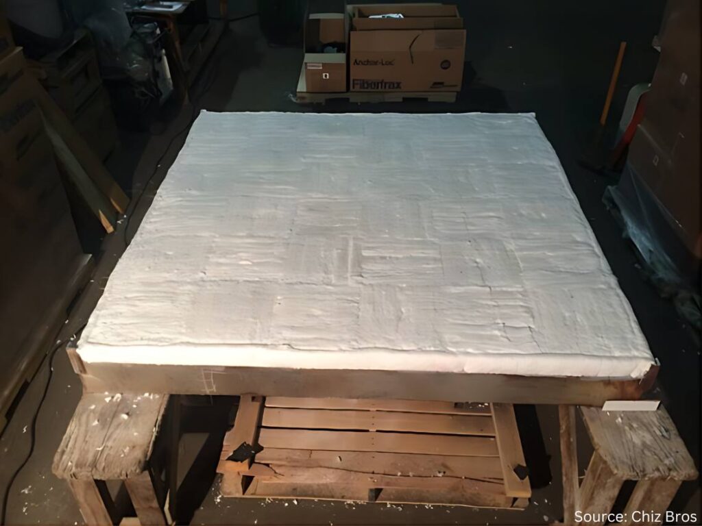
Mark Rhoa: I describe it to people who may not know much about it by comparing it to the Pink Panther insulation that people may recognize up in their roof or in their walls. Ceramic fiber is white, but picture that insulation for 2300°F. That’s what ceramic fiber is, and it’s a form that we sell the most of right now.
Ceramic fiber
You can take that and cut gaskets out of it. You can form it into hard boards through a vacuum forming process. You can take it folded into what we call ceramic fiber modules; your furnace probably has modules in it if it’s a traditional gas-fired or electric furnace. Ceramic fiber products typically aren’t used on the vacuum side of things. People with all vacuum furnaces are probably not going to be using ceramic fiber. There are cloths that are ceramic fiber based as well. There’s a bunch of other ways it’s used.
Ceramic fiber is made of a blown, spun glass. Essentially what you’re doing is dropping the liquid aluminum silica mixture, and it gets blown or blown and spun at super high temperatures. I’m not going to get into the details of the differences there, but whether the stream is blown or is spun on wheels will determine the tensile strength of blanket.
In the grand scheme of things, what you’re doing is collecting all that fiber and getting it onto a mechanism that’s moving along a conveyor belt. Then it’s getting needled from each side to interlock the fibers to make a 26” wide blanket. It’s going to be trimmed off an inch when it goes through, and at the end you have a 24” wide x 1” thick, 8-pound density roll coming out.
Those densities can vary based on how much fiber is going into it. It’s pounds per cubic foot. But when you’re using a 1” thick piece, it’s divided by twelve from a weight standpoint. The fiber you’re needling in there determines the density.
And there are slightly different chemistries for 2300°F, 2600°F, and the most expensive would be 3000°F polycrystalline. The process to make that is a little bit different, too.
But most people are probably more interested in what we’re doing with it. What’s the Chris Farley line in Tommy Boy? We’ll keep it PG, but “take a butcher’s word for it” — take our word for it; it’s made the right way.
Now we can get into how it’s actually used.
Doug Glenn: It’s basically like insulation in your house, like you said. That’s probably the best description of it for people that need to know. But it can obviously go to a much higher temperature.
In an industrial setting, why would you use fiber versus a castable or brick?
Why Fiber? (08:28)
Mark Rhoa: Ceramic fiber is a great insulator. We’ll probably get into why a better insulator is important for decarbonization efforts and things like that.
It’s certainly a better insulator than castables, easy to install, and easy to use. The main reason it’s preferred is for its insulating value and ability to have varying temperature ranges, which you can certainly do with castables and brick.
But to put brick in a wall 12” thick, for argument’s sake, you will need four layers of 3” brick on there. With ceramic fiber, you can take one 12” x 12” module, shoot it onto the shell, attach it, and be good to go from there.
The main thing would be longevity and stuff like thermal shock value. One of the things you have to worry about with castables and brick — maybe not as much with IFB but standard brick — is the heat cycling. Heat treat furnaces are a great example of that.
That door is opening up a lot, so the air is coming in there. People probably see it in their furnaces. The castable is going to want to crack because it’s not designed for thermal shock like ceramic fiber is.
There are certainly applications that you wouldn’t want to use ceramic fiber for. If you’re looking at a traditional heat treat furnace, it depends on how the load is supported: If the floor is the refractory, it is actually supporting the load, and you’re going to want some sort of brick, some sort of castable. Fiber is going to be soft, compressed, and get beat up. You can’t necessarily put it everywhere, but there are areas where it may be up for debate on.
You can use a brick or you can use fiber in the wall. Traditionally, you’re going to use fiber for the insulated value, thermal shock value, installation, and weight; it’s a lot lighter.
A lot of heat treating furnaces are small compared to the massive furnaces in steel melting. They’re going to ship heat treating furnaces. With ceramic fiber, a 12” x 12” fiber module, 12” thick, weighing roughly 12–14 lbs. is 5–10x lighter than brick or castable.
Repairability (10:51)
Doug Glenn: How about addressing the repairability issues between castable and brick and fiber?
Mark Rhoa: Fiber, especially if you’re getting into higher temperatures, can have some shrinkage to it. But you’re able to repair fiber a lot easier. If you wreck a little bit of fiber, you can get in there and get it repaired quickly. With a brick or castable everything’s tied together as either a monolithic piece or a bunch of bricks that are connected, it can start to become a house of cards scenario where you pull and one goes down then everything goes down.
Doug Glenn: It’s like a Jenga game. You pull that brick out on the bottom and what happens?
Figure 2. “You don’t want to pull out the wrong brick.”
Mark Rhoa: Yeah, you don’t want to pull the wrong brick.
Doug Glenn: You already mentioned the temperature ranges we’re talking about. The standard bottom temperature is 2300°F; the fibers are good up to 2300°F. Then you’ve got 2600°F and then 3000°F. Is that roughly the breakdown when you’re looking at fibers?
Mark Rhoa: I don’t know why they ended up doing this, but for 2300°F ceramic fiber, realistically you only want to use it to 2150°F. That goes along with the shrinkage curve of it. I forget the exact number, but I think it’s like in 24 hours, you get less than 3% shrinkage. Typically, the rule of thumb is that you don’t want to use that full temperature range; you want to give yourself 150°F of cushion to be safe. It will still have shrinkage after that up to that temperature.
I don’t know who ever thought of that; it was probably some genius marketing guy to get a little extra.
Fiber Shrinkage (12:57)
Doug Glenn: You’ve mentioned shrinkage a couple different times. Why does that happen with ceramic fiber? And how does that impact installation?
Mark Rhoa: When ceramic fiber hits its operating temperatures, it shrinks up. On the chemistry side, I don’t have an answer there. But we factor in compression to help alleviate when something shrinks. It’s already pushing out against something. It still keeps its resiliency (it wants to pop back out), and that’s factored into every design.
If you’re doing 12” modules, you’ll have a batten strip between them. That makes up for some of the shrinkage that may come where there’s not compression. Any sort of design we would do, or probably anyone would do, is going to factor in shrinkage. You don’t want to just put something in there, and when it shrinks, it leaves a gap. You want to make sure you have something in there that’s going to fill that gap; and that’s typically for modules.
Now if you’re getting to a low temperature, we’re talking about a furnace at 1200°F, you’re not going to have to worry about shrinkage. Even in some of those furnaces, you’ll see designs we call wallpaper — a pin’s exposed and you’re layering on top of it. You’re just kind of overlapping gaps, but you’re not going to have any shrinkage there, so you don’t really have to worry.
Figure 3. Avoiding gaps when shrinkage occurs
Doug Glenn: There is one question I did want to ask you when we were talking about the different temperature ranges of 2300°F, 2600°F, and 3000°F. Are the chemistries between those different?
Mark Rhoa: They’re all alumina silica based. 2300°F is like 50% alumina and 40% silica. They’ll typically inject some zirconia in it, maybe around 15% zirconia. That gives it the extra boost. Alumina is what drops down.
We don’t want to get into every example, but it does have a lower aluminum content. Sometimes in aluminum melting you can get some flexing because there’s zirconia in there, so you need to know the exact application.
And then the polycrystalline, what people call the 3000°F, would be 72% alumina. And that’s made in a calcined process. The 72% alumina is the key factor.
You can also have super high aluminum blankets. Saffil® is the typical brand name. And that’s a 95% plus alumina. That’s for high hydrogen atmospheres, stuff where there’s bad attacking, bad off gassing. The alumina is usually more resilient to that. Some aerospace applications have that stuff spected in for effectiveness and also because they probably have government money. Why not pay for the highest quality, most expensive thing, right?
Electric Element Modules (18:32)
Doug Glenn: You mentioned modules before, but I want to take a little bit of a different angle. The modules you were talking about have no type of heating element in them. They’re just simply the insulating modules that you put on the side of the wall, side by side, maybe alternating the orientation. But what I want to talk about are electric element modules. Can you describe what those are and why you are using them? And maybe hit on the decarbonization or electrification element of those?
Mark Rhoa: Traditional fiber modules are used in a gas furnace, even an electric furnace that may be heated by glow bars or radiant tubes or something like that. That’s going to have a similar penetration there.
One of the systems we call our ELE system. I’d say in the last two years we’ve probably had as many inquiries or conversations about going to these electrically heated modules than we have in the past 5–10 years combined. A lot of that has to do with companies wanting to get away from gas, or they’ve got pressures for different environmental or cost saving reasons.
What we’re doing with that is hanging the elements on the ceramic fiber module. And when they show the pictures of this one, there’ll be one in there. But that allows us to do a modular system where they can get a lot of power on those walls, and it lets us keep a lot of the same insulating value from using modules without having to use brick or a super heavy element in the sidewalls for support.
Electric Element Modules
When someone says we’re putting this many BTUs of gas; here’s the load, size, weight. We do the electric calculations to see how many kilowatts of power we need to pump into this furnace and elements in order to heat something up just like you would do with gas.
And rest assured, someone a lot smarter than me does those calculations. I’m just a pretty face that gets to sell them. But this is something that we’re seeing a lot of. There’s a big push coming from the government and boards of directors.
Doug Glenn: It’s going to help companies reduce their carbon footprint if that is their desire.
I have a question for you about those and specifically about installation. If every module needs a power source, do you have to punch a hole in the furnace wall for every module, or can you interlink them and only have one power source at the end of the chain?
Mark Rhoa: Good question. I didn’t do a good job describing that, but the modules will still go in just like a regular module. They actually have an extra set of ceramic tubes in them. When we do our design, we know where the elements are going to be hung.
If you have a 10-foot wall, you’re not going to have ten 1-foot pieces of element. You’re going to have an eight foot string of elements along that wall, and they will be hooked into the loops. One end of the hook will go on a loop, the other end will go on the ceramic tube that’s inside the module.
If you have a 12’ x 12’ high wall, and you may have a 10’ element in there, you’re probably only going to have four penetrations, maybe more. It’s not going to look like Swiss cheese. They’re going to be linked together.
These are all based on the number of zones in a furnace, too. Some super high aerospace applications are going to have everything super fine tuned just like it is with burners. If you think about how certain applications require way more precision and control over burners, the same thing can be true for these elements, too. The more precision and control you need, the more complicated it’s going to be just like it is with burners.
Before you hang the elements, you could look in that furnace and it would look just the same as a regular gas-fired furnace without the burners. Then you start hooking the elements on the walls. And the pictures of it are helpful.
If anyone has seen Home Alone, he goes into his basement and his furnace is shooting out all the flames. If you walk into a plant and can see that, getting that to seal will prevent heat from leaving.
Mark Rhoa
Furnace Doors (23:52)
Doug Glenn: When I think about ceramic fiber (which you don’t often see it inside a furnace if the door is closed), but a lot of times you’ll see it jammed in around the doors. To me it doesn’t look like that’s the way it’s supposed to be. So, doors are an issue, right? Can ceramics help with that?
Mark Rhoa: In heat treating furnaces, the temperatures aren’t totally crazy like forging furnaces where there’s a lot of shrinkage so they’re replacing it all the time. In heat treat, the temperature is lower. The main wear and tear items we see when we’re working on a repair with a client are around the doors because they’re getting the mechanical abuse of constantly changing. In some of the decarbonization talks I’ve attended and given at trade shows, we’re really looking at ways to save heat. Just making sure your door is sealed properly can do wonders.
If anyone has seen Home Alone, he goes into his basement and his furnace is shooting out all the flames. If you walk into a plant and can see that, getting that to seal will prevent heat from leaving.
You hear all these decarbonization talks, you see all these millions of dollars being thrown around, and, really, you can make a huge difference on a shoestring budget by simply making sure your door is sealing the way it’s supposed to seal.
If you can see the heat coming out, it’s like dollars flying out of your furnace on a game show. You’d have people lined up for that every day of the week.
So you hit the nail right on the head there. A really small, easy way to make a calculated decarbonization effort is making sure you have a door plan or you’re changing it.
It’s the same thing with tuning burners. Little tunes to a burner can save tons of gas and tons of CO2.
Figure 5. Heat leakage from doors needing maintenance
Doug Glenn: Making sure you’re maintaining good flame curtains on a continuous furnace, all that stuff just keeps the heat from coming out.
Did I see correctly that you guys do door repairs?
Mark Rhoa: We’ll do door repairs in our own shop. If someone ships a door to us, we’ll do the realigns there. About 20 years ago, we stopped having our outside contracting arm. Now we’re not doing any of the fieldwork. But we do realign doors in our shop.
Fiber is pretty easy to work with. Door perimeters are something that can easily be done by someone’s own maintenance crew. Maybe they’ll need one of our sales guys there making sure they do it right the first couple times. But it’s not a hard thing to do. If you have a 12 inch module perimeter, switch those 40 modules out once a year and you’ve got fresh gas savings.
Ceramic Maintenance (27:07)
Doug Glenn: Let’s shift gears a bit and talk about typical maintenance of ceramic-insulated furnace. What do we need to be careful about? Any tips you can offer?
Mark Rhoa: There’s another really affordable thing you can do. You can probably sometimes see this if you have a hot spot where paint’s chipping off or melting or if you have a temperature gun you can find those hot spots. If you see heat on the outside, then you’re typically going to see some sort of crack or gap on the inside. Make sure you have scheduled maintenance downtime with your furnace and stuff in any of those cracks.
If you’ve got a really big furnace or a continuous furnace, roller hearth, furnace type thing, the roll seals are some of the areas where you’re going to end up losing a lot of heat because there’s more wear and tear there. There’s just more opportunity for expansion and contraction.
We do have ceramic pumpable products. We call it liquid ceramic fiber for when there’s a hot spot on a furnace, it’s a big one, and you can’t get in there, you can drill a little hole on it, pump it in from the backside, and fill that up. You don’t want to start making your furnace Swiss cheese and poking holes.
It can be a quick stopgap. If you can’t get inside the furnace, fill it in from the backside, too. Because you don’t want those hot spots to grow and cause problems. You don’t want them to get to the hardware.
Then you may have a module where the hardware gets too hot in the backside and the module ends up falling in. That’s one scenario. You can get out ahead of it by filling some of those gaps.
For a refractory on the hearth, too, if you don’t want to replace a hearth you can find a refractory contractor to come in and (if you have a big furnace) spray gunite over the hearth to fix any gaps or cracks.
Doug Glenn: That’s more for castable, though?
Mark Rhoa: Yeah. On the fiber side of things, you’re looking for hot spots.
Doug Glenn: The takeaway is to make sure you’re taking regular thermal imaging of your shell of the furnace. If you’re noticing some hot spots, it’s time to investigate.
Mark Rhoa: If you have a lot of furnaces, you can get a thermal imaging gun for a couple hundred bucks and really [keep an eye out].
An even bigger deal are the doors. It will blow your mind if you look at the temperatures on a fresh door seal versus an old one. Have a temperature gun to justify to your bosses. “Hey, we realigned this, and it is 150°F. This time last year it was 250°F–350°F degrees.” Common sense can tell you we’re losing more heat when it’s like that.
Concerns with Free Floating Fiber (30:20)
Doug Glenn: Can you address the concern that some furnace users have regarding free floating fiber, especially in furnaces where there’s high velocity airflow?
Mark Rhoa: Talking about the benefits of fiber versus brick and castable, one of the benefits of the hard refractory is it does better with high velocities. Patriot furnaces may have a fan in there. Typically, they’re not getting high enough where we need to worry. You can put coatings on the fiber or rigid dyes or things like that to harden them.
But from a health and safety perspective, anytime you’re working with fiber you want to make sure you’re wearing a mask. They have warning labels on them. It’s not like it was back in the day. I’m not allowed to say the “a” word [asbestos]. So there are not worries like that anymore, either. But refractory ceramic fiber still does have a warning label on it.
We do have body size soluble fiber. Alkaline earth silica (AES), non RCF fiber, a bunch of fancy names, are more prevalent in Europe because of their rules. California’s got a lot of rules, too….
But we do supply that as well. It doesn’t have any sort of warning labels on it.
Obviously, when you’re working with it, you want to wear a mask because dust in general isn’t good. But it’s naturally soluble for your body.
It’s not quite as strong. It can have more shrinkage at lower temperatures. But it’s best to talk with somebody and understand what the right product is to use. Things can be a little worse, but there is a slight move in the direction of body soluble fiber because there are no warning labels on it. But it’s not drastic.
Some of the similar concerns foundries have is with sand and airborne silica now. Technically, I guess going to the beach we’d have airborne silica, too. There’s justification to taking those precautions, but it’s certainly not all doom and gloom.
The ceramic fiber is essentially little glass beads, like a tadpole head and then there’s a fiber tail that interlocks.
Mark Rhoa
Doug Glenn: What I heard wasn’t so much a human safety issue. It was the use of ceramic blankets inside of an aluminum annealing furnace: If the fibers got airborne, they would come to rest on the coils and mess up the strip going through. And then you have contaminated coil or it’s marked.
Mark Rhoa: The issue with that is the shot on the fibers. The ceramic fiber is essentially little glass beads, like a tadpole head and then there’s a fiber tail that interlocks.
Fiber has come a long way. The shot content is way lower than it used to be. But it’s certainly a concern if that gets on a coil and then it goes through the rolling mill and you make a small dent in all the glass … yeah.
A lot of different things can be done for that. People put up cladding; people rigidize it to lock the fiber in.
There are definitely concerns for all the applications. Big aluminum homogenizing furnaces may have that. Traditional, smaller batch annealing furnaces may not.
It would be the same thing if a little piece of brick chipped off onto [indiscernible]. The worry with some of the fiber stuff is it’s obviously a lot smaller so you don’t get to see it.
Doug Glenn: It’s a lot more conducive. You can imagine the difference between a brick being hit with high velocity air and a fiber, you would just see the degradation of the fiber. A fiber ceramic blanket would go down quicker.
Induction at Chiz (35:20)
I have one other question for you about Chiz. Your company was one of our sponsors at our recent Heat TreatBoot Camp, and I was surprised when you had an induction coil on your table. If you don’t mind, address what it is Chiz is doing in the induction area?
Mark Rhoa: We were using the company down the road from us, Advanced Materials Science (AMS), to machine some of our fiber boards and bricks that were a little too complicated for what we had in-house at the time. They have some really good CNC equipment up there. The guy who owned AMS was looking to sell off that branch of his business. We had been one of his bigger clients, and we came to an agreement to it; it’s still out of the same building, same equipment, same guys that are doing all the good work.
We started getting in there and saw a lot of the induction heating equipment on the client list — a lot of those electrical plastics, high temperature plastics, electrical marinite and transite boards, which we got into a little bit in the Chiz Brothers world but didn’t fully dive into it because the temperatures are a little bit lower than what we’re dealing with on the ceramic fiber side of things.
It’s been really good for us. They’ve got great machining capabilities down there to machine some of these complex parts out of NEMA G10 and marinite and transite and all these terms that were relatively new to me when we bought them.
It’s really helped us at some of these trade shows because three types of furnace guys walk by: the gas-fired guy, he’s my best friend; the induction guy used to be like, “There’s not that much we can do with you.” Now, we can do a lot with them.
And then I’m still trying to figure out how I can be happy when the vacuum furnace guy walks by. That will be a different battle for a different day. I’m not trying to get into the graphite felt world. I probably just can’t be friends with everybody.
But it’s been good to get into the induction industry. It’s something that we’ve been growing over the last year or two because we hadn’t been engaged with people quite as much as we had.
Doug Glenn: Well, we’ll look for opportunities for you to be friends with the vacuum people. One thing I know from experience, Mark, you could be friends with anybody. I’m sure you can work it.
Mark Rhoa: I’ll try my best.
Doug Glenn: You’re doing good.
Thanks so much. I appreciate your time and appreciate you being here.
Mark Rhoa: Look forward to seeing you at the next event. For anyone watching, Heat TreatBoot Campwas great. Whether you’re a supplier or heat treater, it’s a good group of people bouncing ideas. It’s a crash course on a hundred different things in two days. I was there to sell stuff, but I learned stuff, too, which was an added bonus. I’d recommend it to anyone watching. It’s a good way to force yourself to get out of the office. I will definitely be back.
Attendees of the 2024 Heat Treat Boot Camp with the Heat Treat Today team Heat Treat Boot Camp Completion Ceremony: (L to R) Doug Glenn, Mark Rhoa, Thomas Wingens
About The Guest
Mark Rhoa Vice President Chiz Bros Eleanor Rhoa, daughter
In the heat treat industry, Mark handles Chiz Bros‘ relationships with various end-use customers as well as furnace manufacturers. Given the critical need for energy efficiency and uniform temperature throughout the heating process, Mark has been able to develop custom refractory and insulation solutions for customers to meet their complex needs. Through participation in the ASM’s Heat Treat Show, MTI’s Furnaces North America,Heat TreatToday’sHeat TreatBoot Camp, and IHEA’s Decarbonization SUMMIT, Mark has been supportive of the industry, but more importantly, has helped countless customers improve their thermal efficiency and profitability. Mark was recognized inHeat TreatToday40 Under 40 Class of 2021.
Are you looking to expand in-house heat treat operations on a brownfield industrial site? These sites can bring complications due to a more restrictive footprint combined with other fixed process conditions. In today’s Technical Tuesday installment, the authors of this case study reveal how to consider available footprint and conveyance mechanism options in a continuous steel reheat furnace, as well as the key design variables for industrial furnaces.
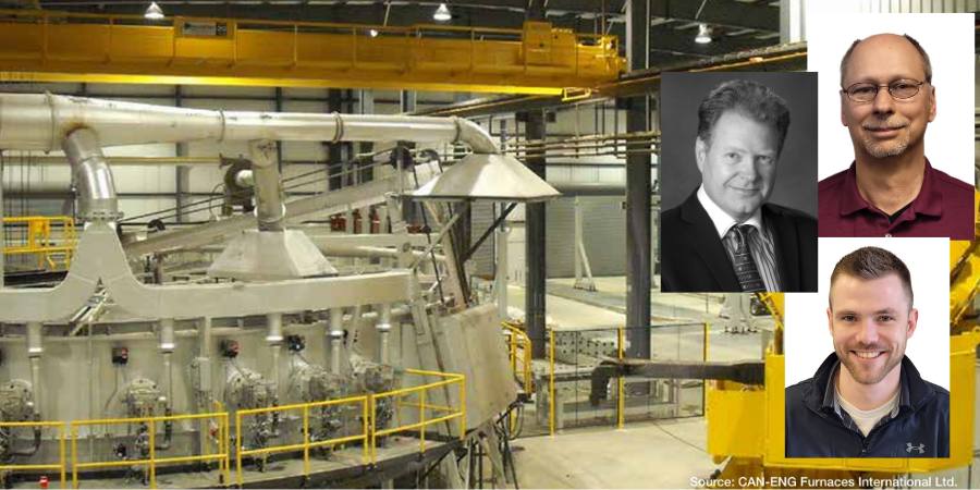
On the research team are the following: Michael K. Klauck, P.Eng., President; Robin D. Young, P.Eng., Vice President — Mechanical Engineering; Gerard Stroeder, P.Eng., Manager — Sr. Technology Specialist; and Jesse Marcil, E.I.E., Project Manager — Mechanical Engineering, all from CAN-ENG Furnaces International.
This informative piece was first released inHeat Treat Today’sFebruary 2025 Air/Atmosphere Furnace Systems print edition.
Introduction
A manufacturer with in-house heat treating had the need to develop a custom furnace for a critical step in the forging process. Specifically, this furnace would be for reheating bottom poured ingots and/or continuously cast round blooms to forging temperatures.
Like all industrial furnaces, the design for such a furnace takes into consideration many factors, including but not limited to:
Production throughput/capacity
Product configuration/condition
Material composition
Target product temperature uniformity
Soak time
Cycle time
Serviceability
Upstream and downstream process integration
Automation
Continuous reheat furnaces that supply steel rolling mills (slabs, blooms) are often designed for very large capacities up to 500 TPH (tons per hour). However, this client’s site was in the 15–30 TPH capacity range. For an open die forging application, this would be considered a low to medium capacity range.
Another consideration was that this was a location with already existing buildings. “Greenfield” sites are undeveloped areas free from prior industrial use; thus, they impose very few restrictions on the layout of the reheating furnace and overall forging cell. In this case, the manufacturer was developing on a “brownfield,” a place with evidence of prior industrial production. Places like these often have the blessing and curse of existing, vacant structures. So, in addition to the design considerations listed above, the physical limitations of a brownfield places constraints on what technology can meet the key performance deliverables.
In this article, we will review how this manufacturer with in-house heat treat was able to customize their furnace to successfully adapt it to the constraints of a brownfield location. The key: An appropriate conveyance mechanism.
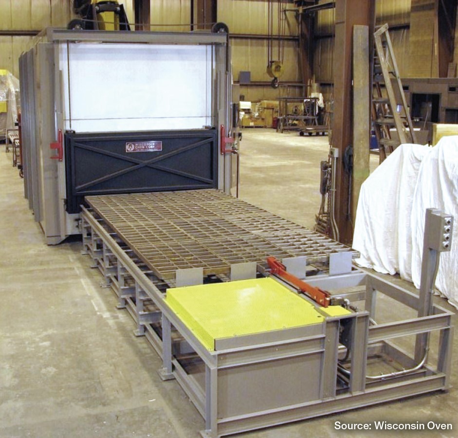
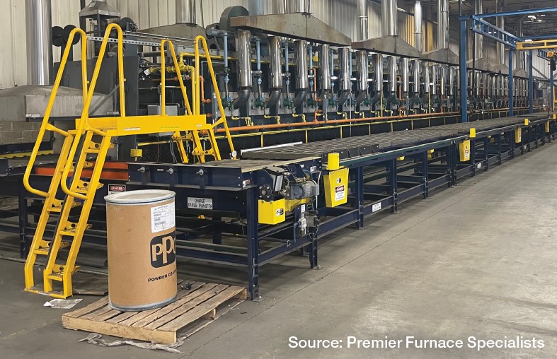
Figure 1. Traditional gantry style loader/unloader
Continuous Furnace Design for Cylindrical Round Reheating
The client’s product was a cylindrical “as cast” (continuous casting or static cast) round of approximate weight 1.5–2 tons with required reheating at 2300°F. With a design production capacity of 15–30 TPH, batch reheating was not a viable option; the main choices for continuous furnace reheating are either a walking hearth or rotary hearth furnace (“ring furnace”).
The scope of plant equipment that had to be installed in custom forging cells consists of the following:
Incoming raw material preparation and cutting
Reheat prior to forging
Forging
Post-forging operations — trimming, shearing, and heat treatment (normalizing, tempering)
Machining and finished goods
For a recent reference site, the incoming raw material preparation, the cutting facility consumed approximately 30% of the overall floor space and the forging machine consumed 35% of the footprint, leaving approximately 35% of the available area for the reheating furnace. A comparison of the advantages and disadvantages of the walking hearth technology and rotary hearth technology was made and presented to the end user.
Some of the advantages of the rotary hearth design included the following:
A smaller overall footprint/lower consumption of building length
Non-water-cooled hearth
Positive product positioning with low risk for movement during conveyance
No complicated pits/foundations
Less complicated drive system
Figure 2. Wrought round bar discharge via a single door system
For this reason, the end user opted for the rotary hearth furnace design over the walking hearth system. A traditional rotary hearth furnace design incorporates two gantry style units, one for loading and one for unloading (see Figure 1). There is a “dead zone” of 10–20° between the charge and discharge which does not contribute to the overall effective heated length.
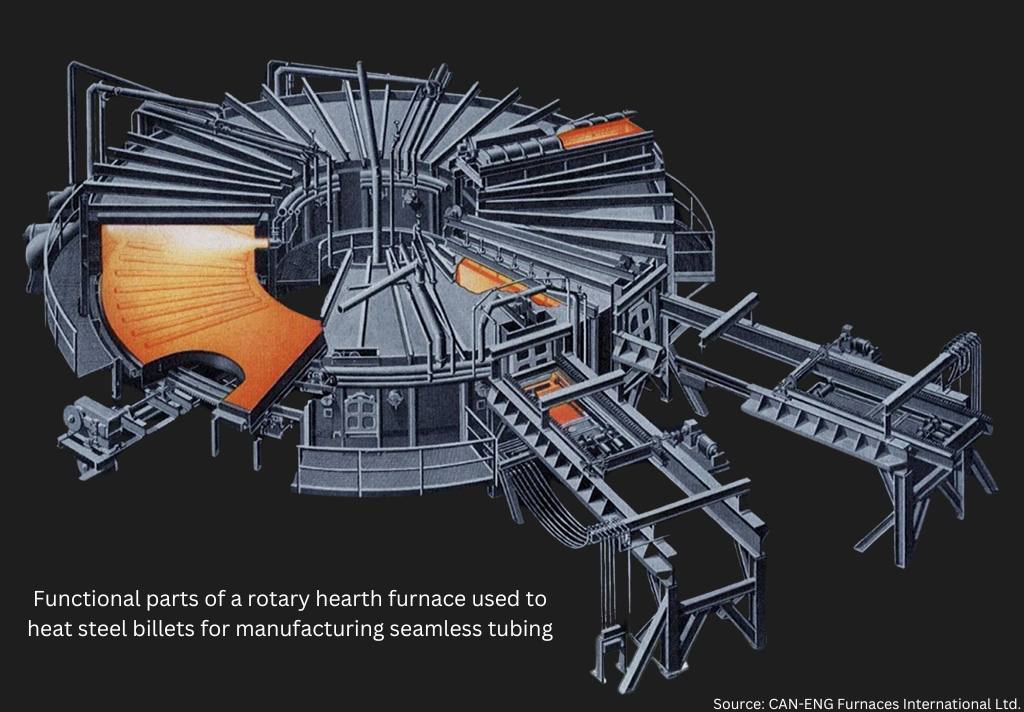
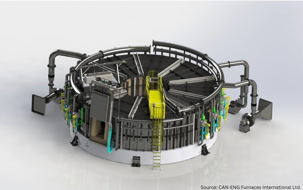
Alternatively, the CAN-ENG design employs a single door vestibule for both charging and discharging. Instead of dedicated mechanical systems with limited degrees of freedom, this design uses a pedestal-mounted, purpose-built furnace tending robot with a 270° axis slew (see lead article image). The result of these design changes is a more effective utilization of the building width for reheating with no dead zone combined with a robot that has considerable freedom when transferring products from furnace elevation to discharge conveyor elevation.
The robotic feature is particularly important when considering pass line differences for various pieces of equipment in a production cell. Some installations cannot have pits due to high water table considerations, and so the flexibility of robot reach combined with the 270° of axis slew yields fewer restrictions for the end user.
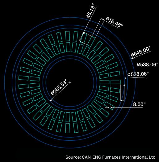
Figure 3. Plan view product layout showing inner and outer charge positions
This rotary hearth furnace can be configured for loading a single long piece or two shorter pieces, one charged towards the furnace inner ring, and one charged to the furnace outer ring, with a suitable gap between the pieces and the refractory walls. This provides considerable flexibility for piece size which is accommodated by the furnace tending robot. Had gantry style loaders/unloaders been used for the charging/discharging functions, the requirement for charging an inner and outer ring of the furnace would have been significantly more challenging.
The overall diameter of a typical steel rotary furnace for 15–30 TPH of production capacity is in the 55’–65’ diameter range (outside of steel service platform). This is dependent on the soak time specified by the end user and the heat up time for the cast or wrought steel product that is charged.
There are many aspects of industrial furnace design that are not covered in this article, and they would include at a minimum:
Refractory — hearth, wall, roof and flue areas
Flue design
Burner type — heat-up zones (both above and below auto-ignition), holding zones (i.e. soak zones
Physical zone separation vs. soft zoning
Drive configuration/drive synchronization
MES or Level II automation and controls
Incoming raw material cutting — carbide-blade, band saw and torch
A full article could be dedicated to each of these subjects. Many details are considered confidential design aspects of the furnace builder.
To speak just on support pieces (piers/bunks), nearly all refractory pier compositions are subject to interaction between the scale that is formed during heating (Fe2O3/Fe3O4) and silicates in the refractory matrix, particularly at reheating temperatures of 2300°F or higher.
Under the conditions of pressure and extremely high temperatures, a low melting point liquid compound of fayalite (iron silicates) is formed at the contact point between the workpiece and refractory pier. This is very undesirable and severely limits the overall pier life. Nickel- and cobalt based super alloys have been used successfully at temperatures up to 2450°F, but these materials can be cost prohibitive, especially considering that 70 or more product locations/pier placements may be required. Unless the product requires very restrictive uniformity in reheating (i.e., titanium ingots), consideration of nickel- or cobalt-based work support pieces is not economically feasible.
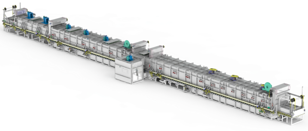
Figure 4. 3D rendering of a CAN-ENG single door rotary hearth furnace
The most important consideration for the forging cell downstream of the reheating furnace is the uniformity of the bar, ingot, bloom or mult as delivered for forging. Accurate determination of the temperature uniformity is often misleading by infrared radiation (IR) methods since primary scale is removed in the breakdown passes and secondary scale reforms in its place. Workpiece thermocouple measurements at defined locations in predrilled test pieces under full load conditions yield the best results for determining product uniformity prior to furnace discharge.
Conclusion
The modern rotary hearth ring furnace at low to medium production capacities of 15–30 TPH offers a compact footprint that has many advantages compared to water cooled beam walking hearth type reheating furnaces. This is particularly important to brownfield sites which need to adapt the existing industrial layout to current production needs. When combined with automated saw cutting and forging cells, an integrated manufacturing solution results in very low man-hour/ton of labor input. As seen in this article, recent reference sites where material handling conveyors, robots, descale units, vision systems and Level II MES (Manufacturing Execution Systems) were supplied have allowed U.S.-based end users to achieve the lowest total production costs, allowing them to be competitive with India and China.
Michael K. Klauck, P.Eng., has nearly 40 years of working in the foundry, steel, commercial heat treating and industrial furnace businesses. He started at CAN-ENG in the year 2000 and has been president since 2012.
Robin D. Young, P.Eng., joined CAN-ENG in the year 2000 and has held progressive positions with the company since then. In his current role, he is responsible for departmental oversight of all aspects of Mechanical Furnace Design as well as the Field Service Team.
Gerard Stroeder, P.Eng., joined CAN-ENG METAL TREATING in 1984, a commercial heat treater, moving over to CAN-ENG FURNACES in 1991. With four decades of process and industrial furnace knowledge, Gerard has expert knowledge of industrial furnace costing and ERP business systems.
Jesse Marcil, E.I.E., is a mechanical engineer working on his Professional Engineer Certification (P.Eng.). Prior to joining CAN-ENG in 2021, he worked in the Engineer, Design — Build of Commercial and Industrial buildings. In his four years with the company, he has now completed several large custom ETO (Engineered To Order) furnace projects.
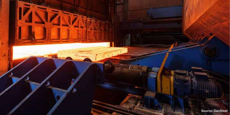
In this article, a team of researchers describe the technical, technological, and metallurgical characteristics in heating large-sized continuous cast slabs made of low carbon microalloyed steels, using the operation at DanSteel’s rolling complex 4200 as a case study. These characteristics ensure high quality heating process of slabs used for production of high-quality heavy plates weighing up to 63 tonnes*, which are particularly in demand in the offshore wind energy and bridge construction industries.
On the research team are the following: Eugene Goli-Oglu, Sergey Mezinov and Andrei Filatov, all of NLMK DanSteel, and Pietro della Putta and Jimmy Fabro of SMS group S.p.A.
This informative piece was first released inHeat Treat Today’sDecember 2024 Medical & Energy Heat Treat print edition.
*1 metric ton = 2204.6 pounds
The production of structural heavy plate steel is a complex multi-step process, the technological steps and operations of which have an impact on product quality and production economics. Slab reheating for rolling is one of the key process steps in the technological chain, directly linked to the quality and cost efficiency of heavy plate production process.
At DanSteel’s rolling complex 42001, continuously casted (CC) slabs are heated either in pusher type furnaces or walking beam furnaces depending on their cross section. In the case of big-size and heavy tonnage slabs with a cross-section of H x B up to 400 x 2800 mm, heating takes place in the latest generation of the SMS group walking-beam reheating furnace, installed in 2022. The main objectives of the installation of the new reheating furnace were the expansion of the product range towards the production of XXL high-quality heavy plates weighing up to 63 tonnes, which are most in demand in the offshore wind power and bridge construction industries, as well as improving the quality, economic, and environmental parameters of slab reheating process.
Figure 1. Effect of reheating temperature on particle size (a) and austenitic grain size (b) in steels (see reference 5) microalloyed simultaneously with Ti and Nb: 1 — steel with low titanium additions (Ti/N=3.24) 2 — steel with 0.02% Nb and Ti (Ti/N=3.33) 3 — steel with increased titanium content Ti/N=4.55
The aim of this article is to describe the technical, technological, and metallurgical characteristics in heating large-sized continuous cast slabs made of low carbon microalloyed steels and how this looks at the DanSteel’s rolling complex 4200.
Metallurgical Characteristics of Slab Heating
Heating of low carbon microalloyed steel slabs is one of the key technological steps in forming the optimal microstructural condition of heavy plates and their surface quality. In conjunction with microalloying, the technological parameters of heating affect such important characteristics as average grain size and uniformity of the austenitic structure, the composition of the solid solution and the type/thickness of the surface scale. In terms of heavy plate quality, the main realized task at the reheating stage is to obtain at the exit a slab with a setup temperature, the minimum temperature gradient along the thickness, width and length of the slab, optimal quality and quantitative condition of the surface scale.
The heating temperature and its uniformity are important to form a microstructure of increased uniformity. It is known2 that a fine-grained austenitic steel structure has an increased grain boundary surface per volume unit, which leads to an excess of free energy of the system, which creates a driving force that determines the subsequent grain growth. The austenitic grain grows exponentially when heated in certain temperature ranges and this grain growth tendency is always present in low carbon microalloyed steels.
Figure 2. Growth pattern of austenitic grains in steels containing various microalloying elements
There are two general mechanisms of austenitic grain growth when heating slabs: normal and abnormal growth. That is, when reaching a certain temperature, which depends on the chemical composition, the austenite grain begins to increase very rapidly in apparent diameter. Abnormal grain growth can be observed in austenitizing steels containing strong CN-forming elements. Anomalous grain growth is not observed in simple low alloyed Si-Mn steels but at heating temperatures of 2102°F–2192°F, the grain grows to very large sizes (200 μm and larger).3
To avoid exponential grain growth of austenite during heating for rolling, dispersed particles that inhibit grain boundary migration are effectively used.4 The undissolved particles inhibit the migration of grain boundaries and thus inhibit the growth of austenitic grains. The nature of the release of particles and their effect on the average size of the austenitic grains of Ti and Nb alloyed low carbon steels is shown in Figure 1. It is important that the slab at the exit of the furnace has a given heating temperature without gradient limit deviations.
The main microalloying elements that form the optimal (fine grain) austenite structure as a result of the solid-solution effect and the formation of nitrides and carbides during slab heating are titanium, niobium, and vanadium (Figure 2).5 Titanium forms nitrides, which are stable at high temperatures in the austenitic range and allow control of the austenite grain size during heating before hot deformation. The binding of free nitrogen (which has a high affinity for carbide forming elements) by titanium has a positive effect on steel ductility and makes niobium more effective. Niobium is an effective microalloying element for refining the austenite grain during heating for rolling.6 It also has the positive effect of inhibiting austenite recrystallization during thermomechanical rolling.7
It is worth noting a number of works8, 9, 10, in which it was shown that increasing the heating temperature of V-Ti-Nb steel and the associated austenite grain enlargement does not significantly affect the size of the recrystallized grain, formed in the temperature range of complete recrystallization after repeated deformation under the same temperature and deformation conditions. This experimental result at first sight contradicts most recrystallization models11, 12, according to which the size of recrystallized austenite grain depends on the initial (before deformation) grain size and deformation temperature.
The microstructure and mechanical properties of the finished product directly depend on the heating temperature and are determined by the size and homogeneity of the austenitic grains, the stability of the austenite itself, influencing the condition of the excess phase and, consequently, the kinetics of its subsequent transformation. For timely recrystallization processes and control of dispersion hardening, it is necessary to balance the uniform fine grained austenitic microstructure and the transition of dissolved particles into solid solution when defining the heating temperature. Also, the heating temperature must be sufficiently high to fully undergo recrystallization in the interdeformation pauses.13 It should also be considered the possible negative phenomena of local and general overheating that occur when heating a slab above a certain temperature for a given steel and lead to a sharp increase in the austenitic grain size. The decreased heating temperature allows for a number of technological advantages: The possibility of reducing the pause time for cooling before the finishing step of rolling, increasing productivity of furnaces due to reduced heating time for rolling, and therefore the mill as a whole, as well as reducing the cost of the product due to saving fuel and reducing losses on scale. However, it should be remembered that some groups of low carbon steels have an optimal temperature range for heating, target temperatures above or below, which increase the heterogeneity of the microstructure. Thus, ensuring uniform heating to a given holding temperature and discharging slabs from the reheating furnace for subsequent rolling is an important technological task and contributes to the formation of austenitic microstructure and solid solution state of low carbon microalloyed steel with increased uniformity.
DanSteel Walking Beam Reheating Furnace
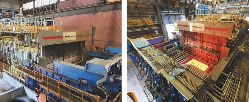
In 2022, DanSteel and SMS commissioned a new walking-beam reheating furnace (Figure 3) with a design capacity of up to 100 tonnes/hour, expanding the range of slabs heated to a maximum cross section of H × B 400 × 2800 mm and improving heating quality. The maximum temperature difference between the coldest and the hottest points on the slabs is not more than 30°C. The new furnace has been designed with a focus on environmental and energy efficiency and has reduced CO2 emissions by 17–18% compared to the furnaces already in operation in the plant.
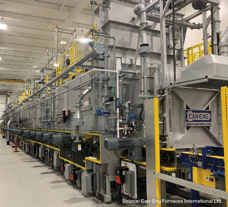
Figure 3. DanSteel walking beam reheating furnace no. 3, (left) general view of the furnace and (right) slab discharging area
The walking beam reheating furnace is for heating cast carbon, low-carbon, and low-alloy steel slabs weighing up to 63 tonnes. The main production characteristics of the furnace as part of DanSteel 4200 rolling complex are shown in Table 1.
Slabs are moved through the furnace by moving the walking beam in four steps: lifting, moving forward, lowering below the level of the fixed beams, and moving the walking beams backwards. The speed of the slab moving in the furnace is controlled by changing the movement intervals between the movement cycles of the beams and depends on the variety of heated slabs. Slab discharging from the furnace is carried out shock-free, using a special machine that moves the slabs from the furnace beams to the mill roller conveyor. The furnace is equipped with a modern automated process control system and a system of instrumentation and sensors that allows the heating of steel without the direct involvement of technical personnel and provides for the measurement, regulation, control, and recording of all operating parameters.
The furnace type is reheating, walking beam, regenerative, multi-zone, double-row, double-sided heating, frontal charging, and discharging furnace. The furnace is designed for natural gas operation with the possibility of a quick conversion, within three weeks, of up to 40% of the capacity for hydrogen operation. The conversion is carried out by means of a minor modernization of the burner’s inner circuit, the installation of hydrogen storage auxiliary equipment and the regulation of the hydrogen supply to the modified nozzles. It is planned that the replacement of natural gas by hydrogen will also reduce the consumption of natural gas by ~40% and hence reduce the negative impact of the process on the environment. Feeding control as well as optimum pressure is controlled by a special automated control system. Table 2 shows the main technical characteristics of the furnace.
The air is heated in a metal recuperator, located on the furnace roof. The combustion products pass between the tube and the air passes through the recuperator tubes. The air is blown by a blower into the recuperator and transported to the burners through thermally insulated air ducts. The gas and air from the common pipelines are supplied to each zone via zone headers, on which flow meters and actuators for flow controllers are installed to ensure an ideal furnace atmosphere with an O2 content of about 0.7–1.0 %.
The furnace has 6 heating zones, 3 upper and 3 lower, with 24 SMS-ZeroFlameTM burners (Figure 4a) for ultra-low nitrogen oxide concentrations and high thermal efficiency.14 The burners consist of a metal casing with external cladding for heat protection, several fuel and combustion air lines, a pre-combustion chamber and an air deflector made of refractory material with high alumina content.
Figure 4. SMS-ZeroFlameTM burners used in DanSteel’s walking beam furnace: a – burner structure; b – flame operation; c – flameless (“invisible flame”) operation
The particular design of the installed burners allows them to operate using three modes:
Flame mode (Figure 4b), used for ignition and at low temperature, but even then, the NOx level remains low thanks to the triple-stage air supply
Flameless mode (“aka invisible flame,” Figure 4c), which ensures high slab heating uniformity over the cross section creating a homogeneous, invisible flame with minimum NOx emissions
Mixed “booster” mode, allowing a 15% to 20% increase in nominal heat input, and a rapid increase in zone temperature if the furnace setting is changed due to a change in steel grade or increased capacity
Figure 5. Heating curves of a 250 x 2800 mm slab in the new reheating furnace no. 3
The combustion gases from the gas combustion heat the metal through direct radiant heat transfer, as do the combustion gases heat the burner units, the furnace roof and walls, which in turn heat the slabs in the furnace through indirect radiant heat transfer. The optimum combination of burner arrangements ensures intensive and uniform heating. The mutual movement of combustion gases and metal is counter current. Combustion gases from the recuperation zone are conveyed by a waste gas duct to the heat exchanger (where they heat the air) and then through a waste gas intake to the chimney and exhausted to the atmosphere. The rotating valve is installed in the exhaust duct between the recuperator and the chimney and is used to control the pressure in the heater.
Figure 6. Heating curves of a 400 x 2800 mm slab in the new reheating furnace no. 3
The skids are cooled by chemically treated water, which circulates in a closed circuit. A dry fan cooling tower is used to dissipate the heat from the cooling water. Steel is charged into the furnace by a charging machine that moves the slabs from the charging roller table to the furnace skids.
Technical Features of Slab Heating
The highly even heating of slabs in furnace 3 of DanSteel is ensured by the optimum arrangement of the burners, flameless fuel combustion, triple skids shift, and warm riders on the skids. The evenness of the slab heating corresponds to a maximum temperature difference in the longitudinal section of up to 20°C, and the maximum difference between the coldest and hottest points of the slab must not exceed 30°C.
Earlier in work15, it was shown that when heating a 250 mm slab in the old furnace no. 2, the maximum temperature gradient was for a long time within 250-300°C, and at the exit of the furnace the slab had a sensitive temperature difference in cross section. Figure 5 shows an industrial schedule of heating slabs cross-section 250 x 2800 mm in the new furnace no. 3. Analyzing thermal and technical data of slab heating for heavy plate production using the new furnace, it should be noted that the slab temperature uniformity distribution during the whole heating period is essential. When heating slab cross-sections 250 x 2800 mm in the new furnace, the maximum temperature gradient does not exceed 130°C (Figure 5). The peak values of temperature gradients are situational in nature and appear only for a short period of time and at times of adaptation of the control model of heating for each specific slab in the active zones of the furnace. For slabs with a thickness of 250 mm the most critical time is the time interval between approx. 90 and 120 minutes during which the upper and lower surfaces of the slab are actively heated. During the last 20 minutes in the soaking and equalizing phase, the temperatures at ¼, ½, and ¾ of the slab thickness reach a maximum gradient of no more than 20°C. As can be seen from the graph in Figure 5, heating of 250 x 2800 mm slabs to a given temperature of 1150°C takes no more than 4.5 hours. It is possible to reduce the heating time, however, with a certain decreasing of quality.
Figure 7a-b. Temperature gradients of 120 mm heavy plate, produced using TM+ACC modes: a, b — top surface thermoscanner data
A similar schedule for heating 400 x 2800 mm slabs is shown at Figure 6. For large cross-section slabs with a thickness of 400 mm, the heating time is in the range of 9–10 hours. The heating time can be reduced to 8 hours, but also with a decrease in the quality of heating towards an increase in the temperature gradient across the thickness of the slab. It should be noted that the temperature increases smoothly in the heating curves at ¼, ½, and ¾ of the slab thickness. From the peaks of the upper furnace temperature curve, the discreteness of the adaptation adjustments of the furnace heating control model can be evaluated.
Heavy Plate Temperature Profile
The DanSteel 4200 Rolling Complex is equipped with twelve control pyrometers and three thermo scanners that measure the temperature of 100% of the top surface of the plate at reference points in the heavy plate production process. The data obtained can be used to accurately and in real time evaluate the temperature uniformity of the plate in width and length direction.
Figure 7 c-f. Temperature gradients of 120 mm heavy plate, produced using TM+ACC modes: c, d (top) — temperature profile of top surface from pyrometer; e, f (bottom) — temperature profile of bottom surface of plate from pyrometer
As an example, Figure 7 shows the results of a scan of the surface temperature of 120 mm thick rolled steel heavy plate after deformation stage is completed and before the start of final cooling in an accelerated cooling unit. Two states of temperature gradients occurring during production are considered: uneven heating and uniform heating. Figure 7a shows the temperature field of a plate with expressed temperature irregularity. The main reason for the marked irregularity in the temperature field of the rolled plate is non-optimal modes of heating of the slab. It can be seen that the central part of the plate has the temperature specified by the technology, while the head and tail overheated by 50-60° C relative to the specified temperature at a maximum permissible deviation of not more than 30°C. Figure 7b shows the temperature field of a plate with a high degree of uniformity. Approximately 95% of the surface of such a plate is at the process-specified temperature with a deviation of ±3°C. The maximum temperature gradient does not exceed 10°C.
The temperature profiles of the top (Figure 7c and Figure 7d) and bottom (Figure 7d and Figure 7e) rolled surfaces, obtained from control pyrometers, show that the nature of the temperature non uniformity is repeated on the upper and lower surfaces of the plate. In the first “non-optimal” case the temperature gradient of the top surface reaches about 76°C, and on the bottom surface: -54°C. In the case of uniform heating, the gradient of the top surface of the plate does not exceed 3–6°C and the bottom surface: 5–11°C.
Preventive Maintenance System
The DanSteel new walking beam furnace is also equipped with an innovative maintenance support tool named SMS Prometheus PMS (Preventive Maintenance System). It consists of a software platform collecting and elaborating the data provided by an extended number of sensors strategically placed over several mechanical components of the furnace, with the goal of predicting possible malfunctioning. The monitored equipment includes the key handling devices, like the slab charger, the slab extractor or the walking beam system, as well as the hot air recuperator, the combustion air fans of the main components of the water treatment fan. The software algorithm is able to extrapolate some data from the sensor measurements to assess the key performance trends of the related component and anticipate the necessity of intervention for maintenance or repair before any actual damage happens.
Figure 8. Dashboard handling — monitoring of the walking beam system
In the example of Figure 8, the trends are shown that correlate the walking beam movement and the cylinders pressure to the slab load inside the furnace. Any significant deviation in respect to the foreseen pattern denotes a movement anomaly and will trigger a notification to the control system, that allows the plant maintenance team to act preventively in view of a potential failure.
Conclusion
A new walking-beam reheating furnace with a designed productivity of up to 100 t/h was put into operation at DanSteel rolling complex 4200. This allowed expanding the range of heated large-size slabs with a maximum cross-section of H x B 400 x 2800 mm and weighing up to 63 tonnes. The implemented project has provided increased uniformity of heating along the thickness, width and length of slabs with average maximum values of temperature gradients in the three directions not exceeding 30°С (80°F) and reduced consumption of natural gas to the level of 31–32 m3/t of finished product. More uniform heating of slabs ensured improved temperature field uniformity of rolled heavy plates. The constructive possibility of a partial transition to the use of hydrogen instead of natural gas was taken into account.
References
I. Sarkits, Y. Bokachev, E. Goli-Oglu, “Production of heavy plates on the rolling mill 4200 DanSteel A/S,” Stahl und Eisen. 2014. no. 4, 57–61.
Imao Tamura, Hiroshi Sekine, Tomo Tanaka, Chiaki Ouchi, Thermomechanical Processing of High-strength Low-alloy Steels (Butterworth-Heinemann, 2013), 256.
Antonio Augusto Gorni and José Herbert Dolabela da Silveira, “Accelerated Cooling of Steel Plates: The Time Has Come,” Journal of ASTM International 5, no. 8 (2008): 358–365.
Y. I. Matrosov, “Complex microalloying of low-pearlite steels subjected to controlled rolling,” Met Sci Heat Treat No. 28 (1986): 173–180.
S. V. Subramanian,, G. Zhu, C. Klinkenberg, K. Hulka, “Ultra Fine Grain Size by Dynamic Recrystallization in Strip Rolling of Nb Microalloyed Steel,” In Materials Science Forum. Vols. 475–479 (2005): 141–144.
S.C. Hong, S. H. Lim, “Inhibition of Abnormal Grain Growth during Isothermal Holding after Heavy Deformation in Nb Steel,” ISIJ International 42, no. 12 (2002): 1461–1467.
K. Hulka, A. Kern, U. Schriever, “Application of Niobium in Quenched and Tempered High-Strength Steels,” Materials Science Forum vols. 500–501 (2005): 519-526.
C. M. Sellars, J. A. Whiteman, “Recrystallization and Grain Growth in Hot Rolling,” Metal Science no. 13 (1979): 87–194.
H. Tamehiro, N. Yamada, H. Matsuda, “Effect of the Thermo-Mechanical Control Process on the Properties of High-strength Low Alloy Steel,” Transactions of the Iron and Steel Institute of Japan Vol. 25, Issue 1 (1985): 54–61.
Sh. Liang, F. Fazeli, H. S. Zurob, “Effects of solutes and temperature on high-temperature deformation and subsequent recovery in hot-rolled low alloy steels,” Materials Science and Engineering A., vol. 765 (2019): 138324.
H. Yada, “Prediction of Microstructural Changes and Mechanical Properties in Hot Strip Rolling,” Proceeding of the International Symposium on Accelerated Cooling of Rolled Steel. Winnipeg, Canada. 1988. 105-119.
W. Roberts, A. Sandberg, T. Siweski, T. Werlefors, “Prediction of Microstructure Development during Recrystallization Hot Rolling on Ti-V-steels,” ASM HSLA Steels Technology and Applications Conference. Philadelphia, USA. 1983. 35–52.
R. Wang, C. I. Garcia, M. Hua, K. Cho, H. Zhang, A. J. Deardo, “Microstructure and precipitation behavior of Nb, Ti complex microalloyed steel produced by compact strip processing,” ISIJ international 46, no. 9 (2006): 1345-1353.
“Innovation in combustion process,” SMS group, https://www.sms-group.com/en-gb/insights/all-insights/innovation in-combustion-process (date of review 2023-03-20).
V. A. Tretyakov, Bokachev, A. Yu, A. N. Filatov, E. A. Goli-Oglu, Development of a digital twin of the process of controlled rolling of thick plate from high-strength low-alloy steels. Message 1. Simulation of slab reheating in continuous furnace with a prediction of austenite grain size before rolling. // Problems of ferrous metallurgy and materials science. 2022. no. 2, P. 30-40.
This article content is used with permission by Heat Treat Today’smedia partner Furnaces International, which published this article in September 2023.
About the Authors:
Eugene Goli-Oglu Head of Product Development, Technology and Technical Sales Support NLMK DanSteel Andrei Filatov Metallurgist Product Development and Technical Sales Support NLMK DanSteelPietro della Putta Vice-President Reheating and Heat Treatment Plants SMS group S.p.A.Jimmy Fabro Head of the Technical Department – Furnace Division SMS group S.p.A.
Eugene Goli-Oglu has worked at NLMK DanSteel since 2013 and has led Product Development, Technology and Technical Sales Support functions for steel heavy plate production. Eugene received his Master degree in Metal Forming in 2007, a second Master’s degree in Economy in 2009, and a PhD in Metallurgy and Thermal Processing of Metals and Alloys in 2012. He has authored/co-authored 90+ publications in technical journals.
Sergey Mezinov has worked at NLMK DanSteel since 2007 as an engineer of the Project Department and process engineer of the Quality Department. In 1995, Sergey graduated as an heat-power engineer. He has authored/co-authored of 2+ publications in technical journals and authored/co-authored two patents.
Andrei Filatov has worked at NLMK DanSteel since 2019 as a metallurgist in the Product Development and Technical Sales Support department. In 2015, Andrei graduated as an engineer physicist, and in 2019, he completed postgraduate studies in Metallurgy and Thermal Processing of Metals and Alloys. He has authored/co-authored 20+ publications in technical journals.
Pietro della Putta is the vice president of the Reheating and Heat Treatment Plants department at SMS group S.p.A. Jimmy Fabro is the head of the Technical Department – Furnace Division at SMS group S.p.A.
Jimmy Fabro is the head of the Technical Department – Furnace Division at SMS group S.p.A.
The Heat Treat Doctor® has returned to offer sage advice to Heat Treat Today readers and to answer your questions about heat treating, brazing, sintering, and other types of thermal treatments as well as questions on metallurgy, equipment, and process-related issues.
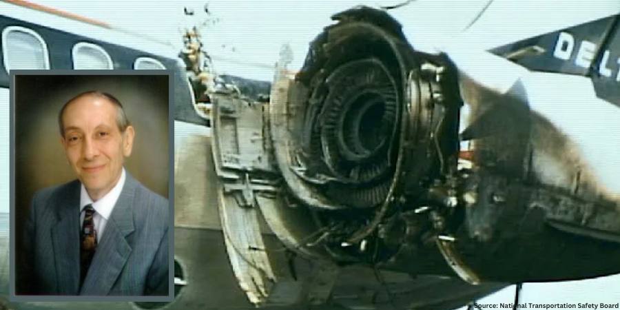
Product failures (Figure 1) can often be traced to deficiencies in design, materials, manufacturing, quality, maintenance, service-related factors, and human error to name a few. Examples of failures include misalignment, buckling, excessive distortion, cracking, fracture, creep, fatigue, shock, wear, corrosion, and literally hundreds of other mechanisms. Let’s learn more.
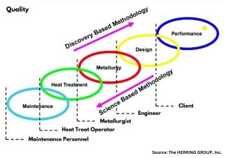
Figure 1. Image of damage to left fuselage and engine; fire damage to nacelle. Source: National Transportation Safety BoardFigure 2.: Model of material science depicting— key interactions and /interrelationships Source: The HERRING GROUP, Inc.
Whatever the source, it is important to recognize that it is next to impossible to separate the product from the process. Performance, design (properties and material), metallurgy (microstructure), heat treatment (process and equipment), and maintenance are all interconnected (Figure 2).
When considering ways to prevent failures from occurring, one must determine the factors involved and whether they acted alone or in combination with one another. Ask questions such as, “Which of the various failure modes were the most important contributors?” and “Was the design robust enough?” and “Were the safety factors properly chosen to meet the application rigors imposed in service?” Having a solid engineering design coupled with understanding the application, loading, and design requirements is key to avoiding failures. If failures do happen, we must know what contributed to them.
Let’s review a few of the more common failure modes.
Fracture Types on a Macroscopic Scale
Applied loads may be unidirectional or multi-directional in nature and occur singularly or in combination. The result is a macroscopic stress state comprised of normal stress (perpendicular to the surface) and/or shear stress (parallel to the surface). In combination with the other load conditions, the result is one of four primary modes of fracture: dimpled rupture (aka microvoid coalescence), cleavage, decohesive rupture, and fatigue.
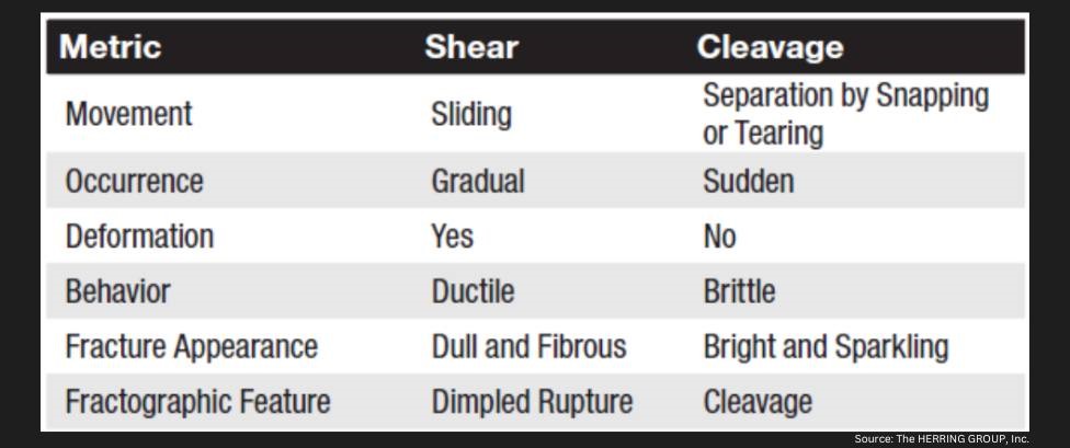
Virtually all engineering metals are polycrystalline. As a result, the two basic modes of deformation/fracture (under single loading) are shear and cleavage (Table 1). The shear mechanism, which occurs by sliding along specific crystallographic planes, is the basis for the macroscopic modes of elastic and plastic deformation. The cleavage mechanism occurs very suddenly via a splitting action of the planes with very little deformation involved. Both of these micro mechanisms primarily result in transgranular (through the grains) fracture.
Fracture Types — Ductile and Brittle
Numerous factors influence whether a fracture will behave in a ductile or brittle manner (Table 2). In ductile materials, plastic deformation occurs when the shear stress exceeds the shear strength before another mode of fracture can occur, with necking typically observed before final fracture. Brittle fractures occur suddenly and exhibit very little, if any, deformation before final fracture. (The following is based on information found in Wulpi, 1985.)
Ductile fractures typically have the following characteristics:
Considerable plastic or permanent deformation in the failure region
Dull and fibrous fracture appearance
Brittle fractures typically have the following characteristics:
Contact us with your Reader Feedback!
Lack of plastic or permanent deformation in the region of the fracture
Principal stress (or tensile stress) is perpendicular to the surface of the brittle fracture
Characteristic markings on the fracture surface pointing back to where the fracture originated
When examined under a scanning electron microscope, fracture surfaces seldom exhibit entirely dimpled rupture (i.e. ductile fracture) or entirely cleavage (i.e. brittle fracture), although one or the other may be more prevalent. Other fracture modes include intergranular fractures, combination (quasi-cleavage) fractures and fatigue fractures.
Fracture Types — Wear
Wear (Table 3) is a type of surface destruction that involves the removal of material from the surface of a component part under some form of contact produced by a form of mechanical action. Wear and corrosion are closely linked, and it is important not only to evaluate the failure but to take into consideration design and environment and have a good understanding of the service history of a component.
Fracture Types — Corrosion
Corrosion is the destruction of a component by the actions of chemical or electrochemical reactions with the service environment. The major types of corrosion include galvanic action, uniform corrosion, crevice corrosion, stress-corrosion cracking, and corrosion fatigue. The mechanisms and effects created by each of these are well documented in the literature, as in Fontana and Greene’s Corrosion Engineering (1985) and Uhlig’s Corrosion and Corrosion Control (1985). It is critical to understand that the effects of corrosion are present to some degree in every failure analysis, which is one of the reasons why protecting fracture surfaces is so critical when sending parts for failure analysis.
Table 1. Differences between shear and cleavage fracture (Data referenced from page 23 of Wulpi, see References.) Source: The HERRING GROUP, Inc.Table 2. Typical characteristics of ductile and brittle fractures Source: The HERRING GROUP, Inc.Table 3. General categories of wear Source: The HERRING GROUP, Inc.
Final Thoughts
To avoid failures or their reoccurrence, it is important to document each step in the design and manufacture process (including heat treatment). In addition, careful documentation of failures if/when they occur is of critical importance as is assembling a team of individuals from different disciplines to perform a comprehensive investigation. This includes a thorough failure analysis to assist in determining the root cause (there is only one) and to avoid it from happening in the future.
Fontana, M. G., and N. D. Greene. Corrosion Engineering, 3e. McGraw-Hill Book Company, 1985.
Herring, Daniel H. Atmosphere Heat Treatment, Volume Nos. 1 & 2. BNP Media, 2014/2015.
Lawn, B.R. and T. R. Wilshaw. Fracture of Brittle Solids. Cambridge University Press, 1975.
Shipley, R. J. and W. T. Becker (Eds.). ASM Handbook, Volume 11: Failure Analysis and Prevention. ASM International, 2002.
Uhlig, H. H. Corrosion and Corrosion Control. John Wiley & Sons, 1963.
Wulpi, Donald J. UnderstandingHow Components Fail. ASM International, 1985.
About the Author
Dan Herring “The Heat Treat Doctor” The HERRING GROUP, Inc.
Dan Herring has been in the industry for over 50 years and has gained vast experience in fields that include materials science, engineering, metallurgy, new product research, and many other areas. He is the author of six books and over 700 technical articles.
For gun barrels, tempering is essential to bring steel to the necessary hardness. But what equipment is needed, and how is this done under a nitrogen cover gas? Explore how low-oxygen temper furnaces — often electrically heated — accomplish this feat.
This article by Mike Grande was originally published inHeat Treat Today’sMay 2024 Sustainable Heat Treat Technologies 2024print edition.
Contact us with your Reader Feedback!
Steel tempering is a heat treatment process that involves heating the steel to a specific temperature and holding it at temperature for a specific time to improve its mechanical properties. Tempering is most commonly performed on steel that has been hardened by quenching. Quenched steel is too brittle for most uses, and so it must be tempered to bring the hardness down to the desired level, giving the steel the desired balance between strength, toughness, and ductility.
Steel is tempered in an oven (often referred to as a “temper furnace”) at temperatures of roughly 350°F to 1300°F, with the exact temperature dependent on the alloy and the desired hardness and toughness. This heating process creates a layer of oxide scale on the surface of the tempered steel, which is unsightly, can weaken it, and can lead to failure or damage. Further, the scale can directly interfere with the intended use of the steel parts. Although in many applications this surface oxidation is not a detriment (it may be removed in a subsequent operation for example), it is not acceptable for certain steel parts.
In order to prevent surface oxidation during tempering, the oxygen can be removed from the oven using nitrogen injected into the heating chamber. More specifically, the nitrogen acts as a protective “cover gas” by displacing the oxygen, reducing the percentage of oxygen in the heating chamber. Essentially, the nitrogen dilutes the oxygen in the oven until it is brought down to a low concentration, such that very little oxidation can occur, preserving the surface quality of the tempered steel.
Gun barrels, for example, are tempered to remove the residual stresses from rifling and other prior processes and bring the steel down to the required hardness.
The tempering process involves heating the barrel to a specific temperature in a nitrogen atmosphere which is very low in oxygen. This helps prevent oxidation and other unacceptable surface contamination that would weaken the steel and make it unsuitable for the rigors of shooting. The internal barrel pressure during the firing of an AR15 rifle, for example, can reach 60,000 PSIG, which generates the 2,200 pounds of force required to produce the typical 3,000 feet per second (2,000 miles per hour) muzzle velocity. Considering these operating conditions and the temperature cycling experienced by the barrels, the tempering process must be performed precisely, and it must be very repeatable. This requires a carefully designed furnace engineered specifically for low-oxygen tempering under a nitrogen cover gas.
Design of the Low-Oxygen Temper Furnace
The key features of a properly designed temper furnace are a tightly sealed shell, a robust heating and recirculation system, a nitrogen delivery and control system, and an atmosphere-controlled cooling arrangement.
The shell of the controlled-atmosphere temper furnace must be tightly sealed so that the factory air, which contains oxygen, is prohibited from mixing with the heated environment inside the furnace. Air contains about 21% oxygen, and if it gets into the interior of the furnace during heating, this oxygen will quickly cause oxidation of the steel. This requires the heating chamber itself to be designed and manufactured with tight tolerances to prevent uncontrolled entrainment of air into the furnace and leaking of the nitrogen cover gas out of the furnace.
Low-oxygen temper furnaces are most commonly electrically heated, and the wall penetrations for the heaters are designed with special seals to preserve the low-oxygen furnace atmosphere. The same is true for the penetrations to accommodate the thermocouples and other sensors, the cooling system, and the door. Special attention must be given to the door opening, and the door itself. As the interface between the hot furnace interior and the room temperature factory environment, it is especially prone to warping, which will allow leaks. There are different technologies used to combat this, including double door seals, water cooled seals, and clamps to squeeze the door against the furnace opening.
Figure 1. Nitrogen temper furnace with a load/unload table
As with a conventional non-atmosphere temper furnace, the heating and recirculation system must be designed with a high recirculation rate and a sufficiently robust heating system to aggressively and evenly transfer the heat to the load of steel. The furnace manufacturer will do calculations to ensure the heaters are sufficiently sized to heat the loaded oven within the desired time, and this is an important part of the technical specification for anyone purchasing a temper furnace. Otherwise, the equipment may not be able to maintain the required production rate.
One of the most critical parts of the atmosphere temper furnace is the nitrogen control system. The idea is to inject sufficient nitrogen into the heating chamber to maintain the reduced oxygen level, and no more than that. Th e most effective design uses a sensor to continuously measure the oxygen level in the furnace, and a closed-loop control system to regulate the flow of nitrogen into it. It is important the nitrogen is high purity (that it contains a sufficiently low oxygen level), and that it is sufficiently dry, as moisture in the heating chamber can greatly increase the likelihood of oxidation.
The process starts by purging the furnace with nitrogen to establish the required low-oxygen environment. Sufficient nitrogen is introduced to the furnace to bring the oxygen level down to the percentage required to heat the parts without undo oxidation. Each time a quantity of nitrogen equal to the interior furnace volume is injected into it, it is considered one “air change.” The number of air changes employed is determined by the desired oxygen concentration in the furnace, with five air changes being a common rule of thumb.
Figure 2. Purging the furnace with nitrogen to reduce the oxygen concentration
Purging is complete when sufficient nitrogen has been injected into the furnace to reduce the oxygen purity to the desired level. The nitrogen flow is then reduced to the minimum required to replace any nitrogen leaking out of the furnace. Some furnace designs simply flood the furnace with a high volume of nitrogen in an uncontrolled manner. Although effective at reducing the oxygen concentration, these systems can waste a profuse amount of nitrogen since it is used at an unregulated rate. A nitrogen control system, therefore, is advisable.
After the load is heated up and soaked at temperature for the required time, the furnace must be cooled down. In an ordinary non-nitrogen furnace, the door is simply opened, or a damper system is actuated, allowing cool factory air into the furnace, while exhausting the heated air. A nitrogen atmosphere temper furnace, however, must remain tightly sealed with the door closed, until the temperature is reduced to below the oxidation temperature, commonly 300°F to 400°F, aft er which the door can be opened. Since the equipment utilizes a well-insulated, tightly sealed design, it would take many hours, or even days, to cool sufficiently without a forced cooling system. For this reason, nitrogen temper furnaces must employ a sealed cooling system that cools the furnace without introducing factory air. This is done with a heat exchanger used to separate the reduced-oxygen furnace atmosphere from the cooling media, which is air or water.
Figure 3. Rear-mounted cooling system
The most effective style of cooling system uses cooling water passing through one side of the heat exchanger and the furnace atmosphere passing through the other. The heat exchanger is mounted to the rear exterior of the furnace, and the furnace atmosphere is conveyed through the exchanger, with dampers included to start and stop the atmosphere flow, thereby starting and stopping the cooling action. There are also systems available that pass cooling air through the exchanger, rather than water. Although less expensive, they provide a much slower cooling rate, which greatly increases the cooling time and reduces the production rate of the equipment, as fewer loads can be processed on an annual basis.
Nitrogen Tempering for Materials Other Than Steel
Some metals other than steel are heat processed in a low-oxygen nitrogen environment, while others do not benefit from this process.
Pure copper can be processed under a nitrogen cover gas to reduce oxidation during heating. If the oxygen concentration is not low enough, spotting of the material can occur, where black, sooty spots appear on the surface. Copper is much less sensitive than steel to moisture in the heating chamber. Copper alloys, such as brass or bronze, are not suitable for processing in a nitrogen atmosphere due to a phenomenon known as dezincification, which removes zinc from the alloy, weakening the material and turning it a yellow color. Titanium is not processed with nitrogen, as “nitrogen pickup” (a nitrogen contamination of the titanium) will occur. Aluminum can be processed under a low-oxygen nitrogen atmosphere to some benefit, which slows down the growth of surface oxidation during heating, but not to the degree experienced with steel.
About the Author
Mike Grande,
Vice President
of Sales,
Wisconsin Oven
Corporation
Mike Grande has a 30+ year background in the heat processing industry, including ovens, furnaces, and infrared equipment. He has a BS in mechanical engineering from University of Wisconsin-Milwaukee and received his certification as an Energy Manager (CEM) from the Association of Energy Engineers in 2009. Mike is the vice president of Sales at Wisconsin Oven Corporation.
For more information: Contact sales@wisoven.com.
Find Heat Treating Products And Services When You Search On Heat Treat Buyers Guide.Com
The future of heat treating requires new manufacturing solutions like robotics that can work with modular design. Yet so also does temperature monitoring need to be seamless to know how effectively your components are being heat treated — especially through being quenched.In this Technical Tuesday,learn more abouttemperature monitoring through the quench process.
Gas Carburization
Contact us with your Reader Feedback!
Carburizing has rapidly become one of the most critical heat treatment processes employed in the manufacture of automotive components. Also referred to as case hardening, it provides necessary surface resistance to wear, while maintaining toughness and core strength essential for hardworking automotive parts.
Figure 1. Typical carburizing heat treat temperature profile showing the critical temperature/time steps: (i) carburization, (ii) quench, and (iii) temper. (Source: PhoenixTM)
The carburizing process is achieved by heat treating the product in a carbon rich environment (Figure 1), typically at a temperature of 1562°F–1922°F (850°C–1050°C). The temperature and process time significantly influence the depth of carbon diffusion and other related surface characteristics. Critical to the process is a rapid quenching of the product following the diffusion in which the temperature is rapidly decreased to generate the microstructure, giving the enhanced surface hardness while maintaining a soft and tough product core.
The outer surface becomes hard via the transformation from austenite to martensite while the core remains soft and tough as a ferritic and/or pearlitic microstructure. Normally, carburized microstructures following quench are further tempered at temperatures of about 356°F (180°C) to transform some of the brittle martensite into tempered martensite to enhance ductility and grindability.
Critical Process Temperature Control
As discussed, the success of carburization is dependent on accurate, repeatable control of the product temperature and time at that temperature through the complete heat treatment process. Important to the whole operation is the quench, in which the rate of cooling (product temperature change) is critical to achieve the desired changes in microstructure, creating the surface hardness. It is interesting that the success of the whole heat treat process can rest on a process step which is so short (minutes), in terms of the complete heat teat process (hours). Getting the quench correct is not only essential to achieve the desired metal microstructure, but also to ensure that the physical dimensions and shape of the product are maintained (no distortion/warping) and issues such as quench cracking are eliminated.
Obviously, as the quench is so critical to the whole heat treat process, the correct quench selection needs to be made to achieve the optimum properties with acceptable levels of dimensional change. Many different quenchants can be applied with differing quenching performances. The rate of heat transfer (quench rate) of quench media in general follows this order from slowest to quickest: air, salt, polymer, oil, caustic, and water.
Technology Challenges for Temperature Monitoring
When considering carburization from an industry standpoint, furnace heat treat technology generally falls into one of two camps, embracing either air quench (low pressure carburization) or oil quench (sealed gas carburization/LPC with integral or vacuum oil quench). Although each achieves the same end goal, the heat treat mechanisms and technologies employed are very different, as are the temperature monitoring challenges.
To achieve the desired carburized product, it is necessary to control and hence monitor the product temperature through the three phases of the heat treat process. Conventionally, product temperature monitoring would be attempted using the traditional trailing thermocouple method. For many modern heat treat processes including carburization, the trailing thermocouple method is difficult and often practically impossible.1 The movement of the product or product basket from stage to stage, often from one independent sealed chamber to another (lateral or vertical movement), makes the monitoring of the complete process a significant challenge.
With the industry driving toward fully automated manufacturing, furnace manufacturers are now offering the complete package with full robotic product loading that includes shuttle transfer systems and modular heat treat phases to process both complete product baskets and single piece operations. Although trailing thermocouples may allow individual stages in the process to be measured, they cannot provide monitoring of the complete heat treat journey. Testing is therefore not under true normal production conditions, and therefore is not an accurate record of what happens in normal day to day operation.
Figure 2 shows schematic diagrams of two typical carburizing furnace configurations that would not be possible to monitor using trailing thermocouples. The first shows a modular batch furnace system where the product basket is transferred between each static heat treat operation (preheat, carburizing furnace, cooling station, quench, quench wash, temper furnace) via a charge transfer cart. The second shows the same heat treat operation but performed in a continuous indexed pusher furnace configuration where the product basket moves sequentially through each heat treat operation in a semi-continuous flow.
Thru-process temperature monitoring as a technique overcomes such technical restrictions. The data logger is protected by a specially designed thermal barrier, therefore, can travel with the product through each stage of the process measuring the product/process temperature with short, localized thermocouples that will not hinder travel. The careful design and construction of the monitoring system is important to address the specific challenges that different heat treat technology brings including modular batch and continuous pusher furnace designs (Figure 2).2
The following section will focus specifically on monitoring challenges of the sealed gas carburizing process with integral oil quench. Technical challenges of the alternative low pressure carburizing technology with high pressure gas quench have previously been discussed in an earlier publication.3
Monitoring Challenges of Sealed Gas Carburization — Oil Quench
Figure 3. “Thru-process” temperature monitoring system for use in a sealed carburizing furnace with integral oil quench — (3.1) Monitoring system entering furnace with thermocouple fixed to automotive gears, product test pieces (3.2) System exiting oil quench tank (3.3) System inserted into wash tank with product basket (Source: PhoenixTM)
Presently, the most common traditional method of gas carburizing for automotive steels is often referred to as sealed gas carburizing. In this method, the parts are surrounded by an endothermic gas atmosphere. Carbon is generated by the Boudouard reaction during the carburization process, typically at 1562°F–1832°F (850°C –1000°C). Despite the dramatic appearance of a sealed gas carburizing furnace, with its characteristic belching flames (Figure 3), from a monitoring perspective, the most challenging aspect of the process is not the heating, but the oil quench cooling. For such furnace technology, the historic limitation of “thru-process” temperature profiling has been the need to bypass the oil quench and wash stations, missing a critical process step from the monitoring operation. Obviously, passing a conventional hot barrier through an oil quench creates potential risk of both system damage from oil ingress and barrier distortion, as well as general process safety. However, the need to bypass the quench in certain furnace configurations by removing the hot system from the confined furnace space could create significant operational challenges, from an access and safety perspective.
Monitoring of the quench is important as ageing of the oil results in decomposition (thermal cracking), oxidation, and contamination (e.g. water) of the oil, all of which degrade the viscosity, heat transfer characteristics, and quench efficiency. Control of physical oil temperature and agitation rates is also key to oil quench performance. Quench monitoring allows economic oil replacement schedules to be set, without risk to process performance and product quality.
Figure 4. “Thru-process” temperature monitoring system oil quench compatible thermal barrier design: (1) Robust outer structural frame keeping insulation and inner barrier secure; (2) Internal thermal barrier — completely sealed with integral microporous insulation protecting data logger; (3) Mineral insulated thermocouples sealed in internal thermal barrier with oil tight compression fitting; (4) Multi-channel high temperature data logger; and (5) Sacrificial insulation blocks replaced after each run.
(Source: PhoenixTM)
To address the process challenges, a unique thermal barrier design has been developed that both protects the data logger in the furnace (typically three hours at 1697°F/925°C) and also protects during transfer through the oil quench (typically 15 mins) and final wash station (Figure 3). The key to the barrier design is the encasement of a sealed inner barrier with its own thermal protection with blocks of high-grade sacrificial insulation contained in a robust outer structural frame (Figure 4).
Quench Cooling Phases
Monitoring the oil quench in carburization gives the operator a unique insight into the product’s specific cooling characteristics, which can be critical to allow optimal product loading and process understanding and optimization. From a scientific perspective, the quench temperature profile trace, although only a couple of minutes in duration, is complex and unique. From a zoomed in quench trace (Figure 5) taken from a complete carburizing profile run, the three unique heat transfer phases making up the oil quench cool curve can be clearly identified:
Figure 5. Oil quench temperature profile for different locations on an automotive gear test piece shows the three distinct heat transfer phases: (1) film boiling “vapor blanket”, (2) nucleate boiling, and (3) convective heat transfer. (Source: PhoenixTM)
Film boiling “vapor Blanket”: The oil quenchant creates a layer of vapor (Leidenfrost phenomenon) covering the metal surface. Cooling in this stage is a function of conduction through the vapor envelope. Slow cool rate since the vapor blanket acts as an insulator.
Nucleate boiling: As the part cools, the vapor blanket collapses and nucleate boiling results. Heat transfer is fastest during this phase, typically two orders of magnitude higher than in film boiling.
Convective heat transfer: When the part temperature drops below the oil boiling point. the cooling rate slows significantly. The cooling rate is exponentially dependent on the oil’s viscosity.
From a heat treat perspective, the quench step relative to the whole process (hours) is quick (seconds), but it is probably the most critical to the performance of the metallurgical phase transitions and achieving the desired core microstructure of the product without risk of distortion. By being able to monitor the quench step, the process can be validated for different products with differing size, form, and thermal mass. As shown in Figure 6, the quench curve profile over the three heat transfer phases is very different for two different automotive gear sizes.
Figure 6. Oil quench temperature profile for different automotive gear sizes (20MnCr5 case hardening steel) with different thermal masses: Passenger Car Gear (2.2 lbs) and Commercial Vehicle Gear (17.6 lbs) (Source: PhoenixTM)
Summary
As discussed in this article, one of the key process performance factors associated with gas carburization is the control and monitoring of the product quench step. Employing an oil quench, the measurement of such operation is now very feasible as part of heat treat monitoring. Innovations in thru-process temperature profiling technology offer specific system designs to meet the respective application challenges.
References
[1] Dr. Steve Offley, “The light at the end of the tunnel – Monitoring Mesh Belt Furnaces,” Heat Treat Today, February 2022, https://www.heattreattoday.com/processes/brazing/brazing-technical-content/the-light-at-the-end-of-the-tunnel-monitoring-mesh-belt-furnaces/.
[2] Michael Mouilleseaux, “Heat Treat Radio #102: Lunch & Learn, Batch IQ Vs. Continuous Pusher, Part 1,” interviewed by Doug Glenn, Heat Treat Radio, October 26, 2023, audio, https://www.heattreattoday.com/media-category/heat-treat-radio/heat-treat-radio-102-102-lunch-learn-batch-iq-vs-continuous-pusher-part-1/.
[3] Dr. Steve Offley, “Discover the DNA of Automotive Heat Treat: Thru-process Temperature Monitoring,” Heat Treat Today, August 2023, https://www.heattreattoday.com/discover-the-dna-of-automotive-heat-treat-thru-process-temperature-monitoring/.
About the Author
Dr Steve Offley (“Dr O”), Product Marketing Manager, PhoenixTM
Dr. Steve Offley, “Dr. O,” has been the product marketing manager at PhoenixTM for the last five years after a career of over 25 years in temperature monitoring focusing on the heat treatment, paint, and general manufacturing industries. A key aspect of his role is the product management of the innovative PhoenixTM range of thru-process temperature and optical profiling and TUS monitoring system solutions.
Now that a new year is in full swing, it may be time to consider that all of the heat treating equipment that’s currently in the workplace has aged along with us. Without proper maintenance in place, you may start to see signs of age, wear, and tear on the high output furnaces that this industry relies on.
This Technical Tuesday,was originally published inHeat Treat Today’sJanuary/February 2024 Air and AtmosphereHeat Treatprint edition.
Jacob Laird Mechanical Engineer Premier Furnace Specialists, Inc./BeaverMatic Source: Premier Furnace Specialists, Inc./BeaverMatic
Most companies have a “workhorse” furnace which is run exhaustively, and even new furnaces that run this way can start looking quite worn after just months of use. Yet decades-old equipment remains in regular use across the country, thanks to knowledgeable maintenance personnel. Since there is somewhat of a void in personnel for this position, here are a few ways to make sure your furnaces keep running into old age.
Contact us with your Reader Feedback!
For roller hearth or belt furnaces with rollers, there can be an extensive number of points in the drive which may facilitate misalignment. Most maintenance crews know to keep chains and sprockets in alignment and to keep bearings well-greased to avoid seizing, but these may not be enough for the high temperatures at which these furnaces typically run. Even though they are turning at slow speeds, the roller’s bearings should be filled with high-temperature grease which is designed not to break down and leak despite the heat constantly being transferred through the roller to the external trunnions (shaft ends). If the bearing already has standard grade grease, it needs to be fully pumped out of the bearing with new high-temperature grease to avoid contamination or reactions between the two which could cause leaking or seizing.
Roller hearth furnace system
For driven rollers, it’s only necessary to “lock-down” the drive side of the roller’s components using cone or dog point set screws (sometimes both) and thread locking compounds. As the furnace heats up, the rollers will expand. By leaving the idle end “free,” it allows a path of least resistance for growth, which allows for the best chance to keep drive mechanisms in-line.
An infrared (IR) thermometer can be a useful tool for diagnosing heat leaks around any furnace and avoiding burns while doing so during operation. It’s important to note that on stainless steel components and the glossy enamel coatings on some furnaces, IR temperature readings likely will not be exact. Quality IR thermometers have adjustable emissivity settings which greatly reduce the error caused by these highly reflective surfaces, but readings still should be used simply as reference points.
FCE insulation
It’s a good idea to occasionally check the furnace case for “hot spots,” and this tool allows it to be done without much effort. These are areas which have a higher than typical temperature compared to the rest of the furnace. This can be one of the earliest signs that insulation quality in that spot has issues. The insulation can be checked and repaired rather than waiting until the furnace’s case steel begins to turn white and burn away, leading to more costly repairs. For brick-lined furnaces in particular, one ideal time to perform this check is during the lengthy dry-out procedure to ramp up to operating temperature after a shutdown. The idle time at low temperatures helps to catch issues before high operating temperatures quickly make them worse. For roller hearth furnaces, simply checking the average temperature of each roller’s exposed trunnions and bearing housings can give insight into potential future issues if individual rollers run hotter than others.
As they say, “The best time to start was yesterday. The next best time is now.” Even a furnace that has seen better days can be maintained, repaired, or rebuilt to keep operations running smoothly and, most importantly, safely.
About the Author
Jacob Laird is a mechanical engineer at Premier Furnace Specialists. Jacob has a BS in both mechanical engineering and physics from South Dakota State University. Among many other things, Jacob is known for his skills in sizing/design of combustion systems, burner assembly, and electrical heating systems.
Roller hearth furnaces are known as the work horses of the heat treating industry. Though they may be common, these furnaces still hold some surprises — namely, their diverse applications, potential to be fully automated, and long life span. Five industry leaders provide insight into the current furnace features and how to optimize them for annealing heat treat. As you read, notice the different emphases each expert addresses.
This Technical Tuesday was originally published inHeat Treat Today’sJanuary/February 2024 Air and AtmosphereHeat Treatprint edition.
Application Determines Customizable Furnace Features
This type of furnace is highly customizable, and, as Tim Donofrio, VP of Sales at Can-Eng Furnaces International explains, knowing the application will determine furnace features.
What Features Do You Offer on Your Roller Hearth Furnace for Annealing Various Materials?
Tim Donofrio Vice President of Sales Can-Eng Furnaces International, Ltd. Source: Can-Eng Furnaces International, Ltd.
The following is based on roller hearth furnaces operating at or above 1400°F.
Annealing furnace features depend upon the material being processed and the metallurgical process being carried out. They can be provided with a wide variety of features for preheating, annealing, slow cooling, oxidizing or bluing and accelerated cooling.
Preheating features include direct or indirect heating applications, under air or controlled atmospheres. Preheating in some cases requires features for burn-off of residual blanking fluids prior to entry into the critical anneal chamber and as such, the off -gas must be appropriately addressed.
Annealing can be a direct or indirect heating application using natural gas, blended hydrogen/natural gas, and electrical energy sources. Process protective atmospheres include N2, Exothermic gas, Endothermic gas, N2 + H2, and H2. In some cases, process atmospheres must be carefully controlled and monitored to very low O2 PPM levels to ensure correct oxides are formed or, alternatively, a bright oxide-free finish is achieved, something very critical when annealing electrical steels for transformer core and motor annealing. Today we see a rise in the use of roller hearth furnaces for the manufacture of transformer core and motor cores, processing electrical steels and amorphous metals. This is largely a result of the electrification of the world.
Post-annealing cooling and bluing are paramount to the process success. In most cases, cooling and soaking stages are provided through the integration of direct and indirect cooling methods that include air, water, and externally chilled atmospheres that can be directly injected into the furnace system and recirculated.
How Is Your Roller Hearth System Unique?
Roller hearth furnaces are the work horse of the industry; they are used for a variety of other heat treating applications. For example, roller hearth furnaces can also be used for low temperature curing, tempering, and aluminum heat treating applications. These lower-temperature roller hearth furnaces do not operate above 1400°F and are built with different fabrication and refractory standards. Of course, additional high temperature applications include neutral hardening, case hardening, carbonitriding, isothermal, and spheroidizing annealing and normalizing.
Roller hearth furnace
Can-Eng Furnaces International offers roller hearth annealing furnaces that meet the stringent demands of today’s manufacturers where safety, product quality, and equipment reliability are at the top of our engineers’ minds during design and development. Can-Eng has developed a strong user base that has benefited from design features that ensure tight temperature control and repeatable thermal profiles while also tightly controlling process atmospheres. This is achieved by integrating some of the best available heating and atmosphere technologies while being combined with state-of-the art automation and robotics to deliver the lowest cost of ownership processing systems to our clients.
What Are Best Practices for Training In-House Operators on Roller Hearth Annealing?
Our company promotes hands-on and classroom multi-level training of operators, maintenance staff, and engineers. This provides a complete and full understanding of the equipment and the opportunity to train within the company for future talent development.
What Are the Furnace’s Operational Advantages?
Can-Eng integrates operator-friendly features that contribute to the reduction in energy and atmosphere consumption while minimizing the carbon footprint and emission levels. Combined with on-board system diagnostics, monitoring, and data collection, these allow for minimal operator involvement.
What Is the Most Common Heating Method?
Today, the most common methods are both natural gas and electric. However, Can- Eng works to integrate features that provide our partners with the benefits of reusing waste heat sources such as flue gases within the system or facility to improve operating efficiencies.
What Are the Challenges in Operating This Type of Furnace?
These (atmosphere control, maintenance, uptime, and temperature control) are all typical challenges that are addressed in design. The key is to design flexibility, ease of use, and operator-friendly features to avoid problems in the future when the client wants to process different products in a different way.
Training and Maintenance To Optimize Uptime
Bob Brock, sales engineer at AFC-Holcroft, emphasizes the importance of training and maintenance to best operate the roller hearth system.
What Features Do You Offer on Your Roller Hearth Furnace for Annealing Various Materials?
Bob Brock, Sales Engineer, AFC-Holcroft
Roller hearth furnaces are designed to provide greater uptime, ease of maintenance, and trouble-free operation and are always custom-designed to meet our clients’ specific processing requirements.
Modular designs are available to accomplish basic heating, holding, and cooling segments but also to incorporate burn off, cyclic spheroidizing, bluing, fast cooling, and blast cooling under controlled atmospheres ranging from Endothermic to Exothermic gases, nitrogen, hydrogen, and products of combustion. A broad range of material handling automation and control platforms providing total data monitoring, controlling, tracking, and acquisition capability are also offered.
How Is Your Roller Hearth System Unique?
AFC-Holcroft has designed, built, and commissioned hundreds of roller hearth manufacturing, and fi eld support teams have extensive knowledge and experience with annealing, isothermal annealing, normalizing, carburizing, and solution and aging processes for ferrous and nonferrous applications. This expertise has well positioned us in the roller hearth furnace market.
What Are Best Practices for Training In-House Operators on Roller Hearth Annealing?
3D image of annealing roller hearth furnace Source: AFC-Holcroft
We use a two-step approach when training operators on our equipment. First, hands-on training provides the best opportunity to learn equipment operation, startup and shutdown procedures, as well as maintenance tasks. Second, we follow up hands-on training with classroom discussions to further the operator’s knowledge of equipment and the use of our operating manual. Our two-step approach arms our client operational team with the confidence and knowledge they need to be successful from day one.
What Are the Furnace’s Operational Advantages?
Roller hearth furnaces are designed and built with longevity and uptime in mind. From our integrated preventative maintenance reminders, robust construction, and user-friendly controls, it’s not uncommon to see our equipment still in operation for 50 years or longer.
What Is the Most Common Heating Method?
Natural gas continues to be the predominate heating source in North America, although we have seen an increased interest for alternate heating sources like electric, hydrogen, and bio over the last several years. We anticipate this trend to continue as companies invest in minimizing their carbon footprint, and can provide clients with carbon footprint analysis and operational costs on our equipment.
What Are the Challenges in Operating This Type of Furnace?
Routine equipment maintenance is key to operational uptime. AFC-Holcroft offers a wide range of preventative maintenance programs for our clients. The services can be customized to include hot and cold inspections, thermal imaging, burner tuning, and equipment optimization analysis.
Consistency Is Key To Increase Furnace Life
Given that the roller hearth furnace is a continuous system, understanding how the system works and operating at the correct, consistent rate is crucial for success. Jacob Laird, mechanical engineer at Premier Furnace Specialists, dives in deeper.
What Features Do You Offer on Your Roller Hearth Furnace for Annealing Various Materials?
Premier Furnace Specialists (PFS) is capable of building annealing furnaces for a wide range of workloads. We have built small batch normalizing furnaces with simple manual roller hearths, as well as 120+ foot long fully automated annealing roller hearths with multi-zone control and automatic load staging. We also offer a variety of controlled heating/cooling systems and atmosphere generators and gas dryers to provide optimal annealed part quality. Controlled cooling systems may include: radiant tube indirect cooling, atmosphere forced convective cooling, and post-process forced convective cooling with ambient air.
How Is Your Roller Hearth System Unique?
Jacob Laird Mechanical Engineer Premier Furnace Specialists, Inc./BeaverMatic Source: Premier Furnace Specialists, Inc./BeaverMatic
One of the unique uses for annealing furnaces is for soft magnetic steel alloys aft er they have been cold worked or formed. This is often used for products inside electrical equipment such as electric motors or transformers where grain growth and residual stresses may affect the magnetic properties of the material. The most cost-effective process for this heat treatment is through a continuous atmosphere with a reducing atmosphere (often provided by a lean Exothermic gas atmosphere). For this process, the atmosphere requires a specific range of hydrogen alongside a controlled heating and cooling recipe with multiple stages.
Premier Furnace Specialists also provides the accessory equipment that can be required for a complete annealing operation. We will build the Exothermic gas generators (rich and lean), Exothermic gas dryers (air and water cooled), nitrogen/methanol/hydrogen (or other bulk atmosphere) gas trains/delivery systems, water recirculation and convective cooling systems, load management equipment/software, and any other required pre/post processing equipment right here at our facility in Farmington Hills, MI. By building all of the ancillary equipment alongside the annealing furnace, it allows the client to benefit from installation of the entire system at once, identical spare parts across all pieces for easier maintenance, identical control systems with consistent terminology for ease of operator training, a single contact source for all engineering assistance and troubleshooting, as well as a service department capable of quickly responding to requests for both our equipment and any other equipment the customer may already have.
A 16 ½ ft. wide x 9 ft. high x 125 ft. long roller hearth furnace with four
heating zones and two cooling zones. Maximum temperature of 1500°F,
nitrogen gas atmosphere.
Concerning efficiency, combustion heating systems can be customized with preheat and recuperation systems, recuperative or regenerative burners, or multi-legged radiant tubes to minimize gas train complexity and NOx emissions while maximizing efficiency and profitability. Electrically heated systems can be equipped with SCR power controls which minimize temperature swings at setpoint, provide optimum work chamber uniformity by eliminating heat surges, and conserve energy by reducing current draw at operating temperature. Processes can also be equipped with digital atmosphere analyzers, flowmeters, and gauges capable of displaying the remote equipment conditions at localized control stations or on mobile devices.
What Are Best Practices for Training In-House Operators on Roller Hearth Annealing?
Specifically for roller hearth furnaces, operators and maintenance personnel must understand the rollers and drive systems to ensure products continue processing at a correct rate. For continuous systems in particular, drive failures may result in the loss of large volumes of product that often cannot be recycled as well as lengthy purge/shutdown/ startup times.
As an example, chain and sprocket driven rollers just only be locked down on the drive side of the furnace so that thermal expansion allows them to grow on the idle side. Otherwise, the sprockets may walk out of alignment and cause a multitude of long and short-term issues such as rollers seizing and warping, drive faults, load crashes, and timing issues between multiple driven segments.
Th e best practice would be for operators to be trained to understand how major components of the furnace may affect the part quality. This knowledge will also assist in troubleshooting issues that may arise and correcting them before they become worse.
What Are the Furnace’s Operational Advantages?
Roller hearth furnaces can handle a large assortment of part sizes by varying the roller diameters and spacing between them. For small parts, the rollers can be used to drive a mesh/cast belt or convey trays. For long parts, they can rest on the rollers with multiple support points. The bar, pipe, and tubing industries use incredibly long roller hearth furnaces while many industries process heavy wire coils in them. By segmenting the roller drives and utilizing VFDs or servomotors, roller hearth furnaces become capable of staging loads, customizing processing times, and oscillating at temperature to prevent rollers from warping under heavy loads.
What Is the Most Common Heating Method?
Premier has seen a steady demand for gas fired roller hearth equipment, but most quotes nowadays also request pricing for an electric alternative to compare against. The end user’s facility location and local utility regulations are typically the deciding factor.
What Are the Challenges in Operating This Type of Furnace?
A common challenge for any continuous furnace is maintaining consistent production and limiting shutdowns or idle periods. Large continuous furnaces burn up a significant amount of energy even when idling, so any time spent not in production becomes costly. Even when the equipment sits powered down, start-up procedures including insulation dry-outs, inert gas purge requirements, and atmosphere seasoning can take days until production can resume.
However, once consistent production is maintained, part quality, part consistency, and energy efficiency can be noticeably better than batch equivalents.
Issues can be avoided by noting areas of concern as they arise and following routine maintenance procedures until scheduled annual or biannual shutdowns (often around holiday breaks). Then additional time can be given to address potentially major issues with service visits and inspections by OEM service teams.
An Eye on Energy
Reiterating the customizable nature of this style furnace, Ryan Sybo, project manager at SECO/WARWICK USA, comments on the attention on energy usage that clients and suppliers share.
What Features Do You Offer on Your Roller Hearth Furnace for Annealing Various Materials?
Ryan Sybo, Project Manager,
SECO/WARWICK USA
We offer a wide variety of options as a custom furnace company. We can tailor the furnace to meet the unique needs of individual clients. On annealing furnaces specifically, we offer a controlled cool chamber and a steam blue chamber.
Individual roll sections can be started, stopped, reversed, oscillated, and run at the same speed or at different speeds for maximum process versatility.
Atmosphere integrity is assured through welded gas-tight shells, sealing doors, and pressure control systems.
Fast and slow heating and cooling rates are possible. Plus, pre-heating can be employed.
Post-heat treating processes like steam blue are possible.
Furnace doors are specially constructed and insulated for operation within the temperature zones in which they are located, minimizing stress and warpage caused by temperature differences.
Heating and cooling sections incorporate dependable, high-quality components for long-life operation.
High-speed transfer between sections allows closely spaced workloads or work trays with separation during transfer through doors, assures optimum use of hearth space, and minimizes atmosphere mixing. All door openings can be adjusted to workload heights, permitting faster operation and minimizing atmosphere mixing.
How Is Your Roller Hearth System Unique?
The controlled cool chamber offers precise control of the cooling rate. The steam blue chamber is used to develop a blue oxide, Fe3O4, for electrical insulation characteristics.
Our company has been designing and manufacturing furnaces for over 123 years, and we have been exploring new refractory materials and more energy-efficient burners and recuperators, as well as offering state-of-the-art atmosphere controls.
What Are Best Practices for Training In-House Operators on Roller Hearth Annealing?
Our furnaces are all built to the latest NFPA 86 and OSHA standards, however, safety training like HMI is also important.
What Are the Furnace’s Operational Advantages?
Several of this furnace’s operational advantages include:
Continuous Unlimited Work Flow: Provides better efficiency than batch processing since the workload can continuously feed into the furnace.
Quick, Easy Installation: For SECO/WARWICK USA, these are normally built at our manufacturing facility and tested, then disassembled into sections to fit on a truck or shipping container.
Long Life: A 40-year lifespan is typical. Less stress on furnace components from faster or constant temperature recycling when compared to belt, chain, or pusher units.
Smaller Factory Footprint: Manufacturers can save about half of the floor space than with multiple batch units.
Flexible Operation: Roller drives can be slowed, sped up, or stopped. Process parameters can be changed, any atmospheres can be used from H2 to air, plus door separations can be used between sections for better separate processing functions.
Lower Production Costs: Each furnace is custom-designed for continuous operation at the desired operating temperatures. Less waste from heat-up and cool-down cycles used in batch systems and in-line processing makes energy recuperation easier to integrate.
What Is the Most Common Heating Method?
Gas fired is the most common, however, we have been seeing a lot of inquiries for electrically heated roller hearth furnaces.
Geographic location is also a big determining factor because some areas have more access to natural gas that can offer reduced operating costs.
What Are the Challenges in Operating This Type of Furnace?
There are no challenges in operating this type of furnace due to our custom-engineered, user-friendly automatic furnace controls. Preventative maintenance can be included in our control systems to remind operators and maintenance personnel to service the equipment. Furnace data and alarms are logged and ready for download and review.
Leveraging Efficient Designs To Process Heavy Workloads
Kelley Shreve, general manager at Lindberg/MPH, hones in on the significance of roller hearth furnace workload capacity as a lynchpin to heat treat operations.
What Features Do You Offer on Your Roller Hearth Furnace for Annealing Various Materials?
Kelley Shreve General Manager Lindberg/MPH Source: Lindberg/MPH
Our roller hearth furnaces are designed to meet the need for accurate, consistent, and efficient processing of heavy workloads. Features include a sturdy roll design for smooth load motion, high-efficiency heating systems for rapid heat transfer, integrated control systems for accuracy of operation and ease of troubleshooting, and material handling systems that simplify operation. Together, these features provide furnaces that will make operations more competitive.
How Is Your Roller Hearth System Unique?
What separates Lindberg/MPH from competitors is our ability to take standard designs and customize them so they are tailor-suited to meet the exact client specifications and floor plans.
Extensive experience in ultra-clean heat treating helped us improve roller hearth equipment as well. Traditionally designed furnaces have transfer sections open to air, which allows rapid heat loss and causes scaling or discoloration of the work. Our proven design shields the work with a directed flow of protective atmosphere through double-door transfer sections. This also ensures isolation of furnace zones that must not be cross-contaminated. An independent, high-speed roll system minimizes transfer time and heat loss. The sight-ports allow direct viewing of work-in-process for easy troubleshooting. The result is clean, consistent work.
What Are Best Practices for Training In-House Operators on Roller Hearth Annealing?
Lindberg/MPH offers complete installation packages which include installation, startup, and training. In-house operators are fully trained on all aspects of operations while our service technician is present.
What Are the Furnace’s Operational Advantages?
Our roller hearth furnaces combine the latest technology in process controls, atmosphere systems, and material handling systems. These furnaces are designed to carry very heavy workloads at high production rates at the lowest possible operating cost. Other advantages are that a roller hearth can be designed to run a multitude of different processes as required.
What Is the Most Common Heating Method?
Roller hearth furnaces can be supplied with either gas fired or electric heating. Gas fired Single End Recuperated Tubes (SERT) provide economical, rapid heating. Electric heating offers reliable, low-maintenance operation using elements tailored to atmosphere application.
What Are the Challenges in Operating This Type of Furnace?
Annealing produces
parts with reduced
hardness and a uniform
microstructure as a
preparation for further
processing. The furnace
has a high-heat section
followed by a controlled
cooling module.
Endothermic, Exothermic,
and nitrogen-methanol
atmospheres are typically
used.
A challenge for this type of furnace is proper maintenance. Operators should manage this challenge by monitoring the preventative maintenance (PM) features and indicators that are available. Setting in place and following a regular PM schedule is going to help ensure the equipment operates dependably and problem free.
How often do you think about the intelligent designs controlling the thermal loop system behind your heat treat operations? With ever-advancing abilities to integrate and manage data for temperature measurement and power usage, the ability of heat treat operations to make practical, efficient, and energy-conscious change is stronger than ever. In part 1, understand several benefits of thermal loop systems and how they are leveraged to comply with industry regulations, like Nadcap.
This Technical Tuesday article by Peter Sherwin, global business development manager – Heat Treatment, and Thomas Ruecker, senior business development manager, at Watlowwas originally published inHeat Treat Today’sJanuary/February 2024 Air & Atmosphere Heat Treat print edition.
Introduction
Heat treatment processes are a crucial component of many manufacturing industries, and thermal loop solutions have become increasingly popular for achieving improved temperature control and consistent outcomes.
A thermal loop solution is a closed loop system with several essential components, including an electrical power supply, power controller, heating element, temperature sensor, and process controller. The electrical power supply provides the energy needed for heating, the power controller regulates the power output to the heating element, the heating element heats the material, and the temperature sensor measures the temperature. Finally, the process controller adjusts the power output to maintain the desired temperature for the specified duration, providing better temperature control and consistent outcomes.
Performance Benefits
Heat treatment thermal loop solutions offer several advantages over traditional heat treatment methods, including improved temperature control and increased efficiency. The thermal loop system provides precise temperature control, enabling faster heating and cooling and optimized soak times. In addition, the complete design of modern thermal loop solutions includes energy-efficient heating and overall ease of use.
Figure 1. Watlow Industry 4.0 solution (Source: Watlow)
Heat treatment thermal loop solutions are integrated with Industry 4.0 frameworks and data management systems to provide real-time information on performance. Combining artificial intelligence and machine learning algorithms can also provide additional performance benefits, such as the ability to analyze data and identify patterns for further optimization. Ongoing performance losses in a heat treatment system typically come from process drift s. Industry 4.0 solutions can explore these drift s and provide opportunities to minimize these deviations.
Heat treatment thermal loop solutions can be optimized using Failure Mode and Effects Analysis (FMEA). FMEA is a proactive approach to identifying potential failure modes and their effects, allowing organizations to minimize the risk of process disruptions and improve the overall efficiency of their heat treatment processes. Historically, this was a tabletop exercise conducted once per year with a diverse team from across the organization. Updates to this static document were infrequent and were primarily based on organization memory rather than being automatically populated in real time with actual data. There is a potential to produce “live” FMEAs utilizing today’s technology and leveraging insights for continuous improvement.
Th e effectiveness of heat treatment thermal loop solutions can be measured using metrics such as overall equipment effectiveness (OEE). OEE combines metrics for availability, performance, and quality to provide a comprehensive view of the efficiency of a manufacturing process. By tracking OEE and contextual data, organizations can evaluate the effectiveness of their heat treatment thermal loop solutions and make informed decisions about optimizing their operations.
Regulatory Compliance
Nadcap (National Aerospace and Defense Contractors Accreditation Program) is an industry-driven program that provides accreditation for special processes in the aerospace and defense industries. Heat treatment is considered a “special process” under Nadcap because it has specific characteristics crucial to aerospace and defense components’ quality, safety, and performance. Th ese characteristics include:
Process sensitivity: Heat treatment processes involve precise control of temperature, time, and atmosphere to achieve the desired material properties. Minor variations in these parameters can significantly change the mechanical and metallurgical properties of the treated components. This sensitivity makes heat treatment a critical process in the aerospace and defense industries.
Limited traceability: Heat treatment processes typically result in changes to the material’s microstructure, which are not easily detectable through visual inspection or non-destructive testing methods. Th is limited traceability makes it crucial to have strict process controls to ensure the desired outcome is achieved consistently.
Critical performance requirements: Aerospace and defense components often have strict performance requirements due to the extreme conditions in which they operate, such as high temperatures, high loads, or corrosive environments. The heat treatment process ensures that these components meet the specifications and can withstand these demanding conditions.
High risk: The failure of a critical component in the aerospace or defense sector can result in catastrophic consequences, including loss of life, significant financial loss, and reputational damage. Ensuring that heat treatment processes meet stringent quality and safety standards is essential to mitigate these risks.
Nadcap heat treatment accreditation ensures suppliers meet industry standards January/February and best practices for heat treatment processes. The accreditation process includes rigorous audits, thorough documentation, and ongoing process control monitoring to maintain high quality, safety, and performance levels.
The aerospace industry’s AMS2750G pyrometry specification and the automotive industry’s CQI-9 4th Edition regulations are crucial for ensuring consistent and high-quality heat treated components. Adherence to these regulations is essential for meeting the stringent quality requirements of the aerospace and automotive industries and other industries with demanding specifications.
Temperature uniformity is a crucial requirement of both AMS2750G and CQI-9 4th Edition, mandating specific temperature uniformity requirements for heat treating furnaces to ensure the desired mechanical properties are achieved throughout the treated components. AMS2750G class 1 furnaces with strict uniformity requirements +/-5°F (+/-3°C) provide both quality output and predictable energy use. However, maintaining this uniformity requires significant maintenance oversight due to all the components involved in the thermal loop.
Calibration and testing procedures are specified in the standards to help ensure the accuracy and reliability of the temperature control systems used in heat treat processes.
Detailed process documentation is required by AMS2750G and CQI-9 4th Edition, including temperature uniformity surveys, calibration records, and furnace classifications. This documentation ensures traceability, enabling manufacturers to verify that the heat treat process is consistently controlled and meets the required specifications.
Figure 2. Eurotherm data reviewer (Source: Watlow)
Modern data platforms enable the efficient collection of secure raw data (tamper-evident) and provide the replay and reporting necessary to meet the standards.
The newer platforms also offer the latest industry communication protocols – like MQTT and OPC UA (Open Platform Communications Unified Architecture) – to ease data transfer across enterprise systems.
MQTT is a lightweight, publish-subscribe-based messaging protocol for resource-constrained devices and low-bandwidth, high-latency, or unreliable networks. IBM developed it in the late 1990s, and it has become a popular choice for IoT applications due to its simplicity and efficiency. MQTT uses a central broker to manage the communication between devices, which publish data to “topics,” and subscribe to topics that they want to receive updates on.
OPC UA is a platform-independent, service-oriented architecture (SOA) developed by the OPC Foundation. It provides a unified framework for industrial automation and facilitates secure, reliable, and efficient communication between devices, controllers, and software applications. OPC UA is designed to be interoperable across multiple platforms and operating systems, allowing for seamless integration of devices and systems from different vendors. The importance of personnel and training is emphasized by CQI-9 4th Edition, which requires manufacturers to establish training programs and maintain records of personnel qualifications to ensure that individuals responsible for heat treat processes are knowledgeable and competent. With touchscreen and mobile integration, a significant development in process controls has occurred over the last decade.
Figure 3. Watlow F4T® touchscreen and Watlow PM PLUS™ EZ-LINK®
mobile application
By integrating these regulations into a precision control loop, heat treatment thermal loop solutions can provide the necessary level of control and ensure compliance with AMS2750G and CQI-9 4th Edition, leading to the production of high-quality heat treated components that meet performance requirements and safety standards.
Continuous improvement is also emphasized by both AMS2750G and CQI-9 4th Edition, requiring manufacturers to establish a system for monitoring, measuring, and analyzing the performance of their heat treatment systems. This development enables manufacturers to identify areas for improvement and implement corrective actions, ensuring that heat treat processes are continuously improving and meeting the necessary performance and safety standards.
To Be Continued in Part 2
In part 2 of this article, we’ll consider the improved sustainability outcomes, potential challenges and limitations, and the promising future this technology offers to the heat treat industry.
About the Authors
Peter Sherwin, Global Business Development Manager – Heat Treatment, WatlowThomas Ruecker, Senior Business Development Manager, Watlow
Peter Sherwin is a global business development manager of Heat Treatment for Watlow and is passionate about offering best-in-class solutions to the heat treatment industry. He is a chartered engineer and a recognized expert in heat treatment control and data solutions.
Thomas Ruecker is the business development manager of Heat Treatment at Eurotherm Germany, a Watlow company. His expertise includes concept development for the automation of heat treatment plants, with a focus on aerospace and automotive industry according to existing regulations (AMS2750, CQI-9).
For more information: Contact peter.sherwin@watlow.com or thomas.ruecker@watlow.com.
This article content is used with the permission of heat processing, which published this article in 2023.
Find Heat Treating Products And Services When You Search On Heat Treat Buyers Guide.Com