Hybrid Heating Systems Unlock Heat Process Decarbonization
As pressure mounts to cut industrial CO2 emissions, hybrid heating systems are emerging as a compelling pathway to decarbonizing industrial process heat. In this Technical Tuesday installment, Dr.-Ing. Marco Rische and Dr. Martin Ennen of ABP Induction Systems GmbH explore how integrating induction technology at the front and end of traditional gas-fired furnace heat treating can reduce energy consumption, improve temperature control, lower operating costs, and offer a realistic bridge to full electrification.
This informative piece was first released in Heat Treat Today’s January 2025 Annual Technologies To Watch print edition.
The metalworking industry is undergoing a profound transformation, as the pressure to reduce emissions and replace fossil fuels continues to shape technological strategies across all areas of the value chain. In addition to melting technology, process heat is increasingly coming into focus — namely the heating, warming, and tempering of materials, which is required in virtually every production process.
With hybrid approaches that combine conventional gas furnaces with induction heating units, energy consumption, CO2 emissions, and costs can be reduced simultaneously. ABP Induction, a global provider of electric heating and melting technologies, has continued to refine and expand hybrid heating concepts over the past several years. Its strategy aims to help shape the path to CO2 neutrality as a partner to the metalworking industry through holistic solutions that balance technological advances and cost efficiency.
The Pressure to Act in the Industry
The starting point is both a challenge and an opportunity; the metalworking industry ranks among the largest industrial producers of CO2 emissions worldwide. The steel industry, in particular, is at the center of the decarbonization debate, accounting for roughly one quarter of global industrial emissions. Natural gas was the preferred fuel for many years: affordable, easy to control, and simple to transport. But with rising CO2 prices and increasing political pressure to decarbonize, the balance is shifting. While primary processes like pig iron production are increasingly shifting toward direct reduction using hydrogen, heat input in downstream processing steps, such as melting, heating, or rolling, still primarily relies on fossil energy sources.
At the same time, the economic landscape is shifting; rising CO2 prices, high energy costs, and the need for stable supply chains are driving a reassessment of conventional technologies and laying the foundation for induction-based burner substitutes to gain economic traction. The megatrends of digitalization, deglobalization, demographic change, and decarbonization are now shaping business decisions across the metalworking industry. After all, the energy policy framework is creating incentives to deploy electric solutions, especially where they can be powered by green electricity. This makes induction — contactless heating of metallic materials using electromagnetic fields — a key technology on the path to CO2 neutrality.
Induction Heating as a Foundational Technology
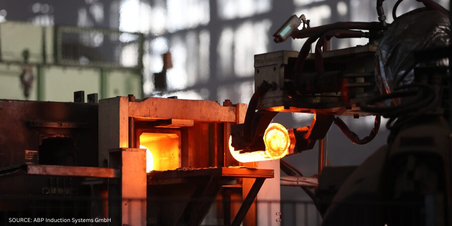
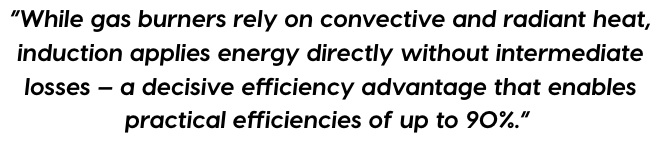
The physical principle of induction is well established. An alternating electromagnetic field transfers energy directly into the workpiece, heating it evenly and in a controlled manner. The advantages lie in high energy efficiency, dynamic controllability, and reliable process stability. While gas burners rely on convective and radiant heat, induction applies energy directly without intermediate losses — a decisive efficiency advantage that enables practical efficiencies of up to 90%.
For many applications, the technology is already widely adopted. In foundries, induction furnaces are increasingly replacing cupola furnace systems, while in forges and aluminum plants, induction systems are used for efficient preheating and heating. New application areas are emerging in the steel sector, particularly in the fields of reheating and heat treatment.
However, the limitations are equally clear; induction works optimally only where the material to be heated is electrically conductive and the electromagnetic field can be efficiently coupled. For large-volume or indirect heating processes, such as those involving gas flows or non-metallic materials, complementary concepts are required.
The Principle of Hybrid Heating
This is precisely where hybrid heating systems come into play. They combine proven induction technology with conventional furnace systems, typically gas-fired continuous or chamber furnaces. The goal is to leverage the strengths of both systems and compensate for their weaknesses.
A typical hybrid system integrates an induction section before or after the gas-fired furnace. When the induction unit is positioned upstream, it handles the rapid heating phase, bringing the workpiece to a defined temperature in a short time, which effectively reduces the load on the gas-fired furnace. It can then operate with reduced energy input. When the induction unit is positioned downstream, it ensures precise temperature control, homogenizes the temperature profile, or compensates for fluctuations in transport speed.
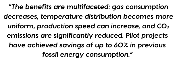
The benefits are multifaceted: gas consumption decreases, temperature distribution becomes more uniform, production speed can increase, and CO2 emissions are significantly reduced. Pilot projects have achieved savings of up to 60% in previous fossil energy consumption.
In addition, the hybrid solution enables a gradual transformation process. Existing furnace systems can continue to be used, keeping investments in new infrastructure to a minimum. This provides operators with an economically and technically viable path to decarbonization and allows them to stay close to the existing process without compromising production reliability.
Process Integration and Control
Hybrid heating systems are highly adaptable. The design of the induction section depends on material, geometry, throughput, and process objective. Modern control technology ensures precise coordination between induction and furnace operation.
In the area of reheating slabs or billets in rolling mills, for example, an inductive preheating station can be installed in front of the furnace. Here, the induced power density is utilized to significantly shorten the heating time. At production rates of up to 200 tons per hour for long products and 1,000 tons per hour for flat products, induction systems achieve electrical efficiencies of 85% to 90%. Downstream of the furnace, a post-heating unit can help maintain a uniform temperature profile, a critical factor for product quality, dimensional accuracy, and potentially reduced wear on subsequent forming equipment. Process stability also benefits. Gas-fired furnaces are sluggish systems whose temperature responds slowly to process changes. Induction systems, on the other hand, can be controlled within fractions of a second, adding a dynamic component to the overall system. This allows temperature fluctuations to be compensated, which helps to prevent product defects.
A Tool for Transformation
The idea of replacing fossil fuel burners with induction systems is not new. Pioneers in the field considered this decades ago and developed alternative processes and methods, but it was never cost-effective. Fossil fuel usage remained cheaper and allowed existing processes to continue unchanged. Now the situation is different.
A key element in ABP Induction’s strategy for electrifying process heat is the Ultra-High-Temperature (UHT) Thermo Jet, a newly developed high-temperature hot gas technology that replaces conventional fossil fuel burners and electrifies industrial thermal processes. The innovation marks a decisive step toward fully electric process heat, demonstrating that even high-temperature applications are feasible without the combustion of fossil fuels.
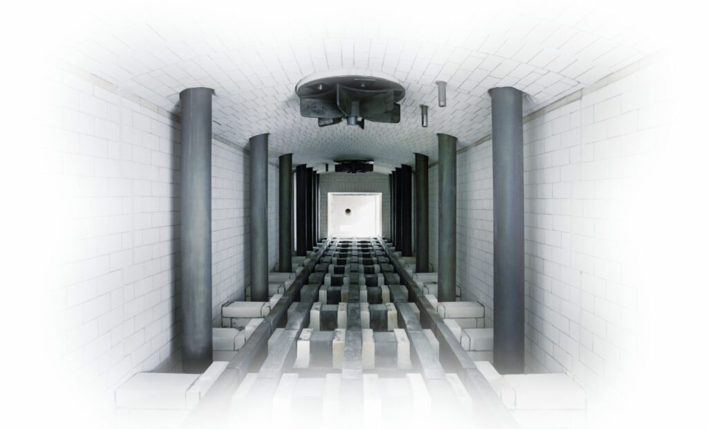
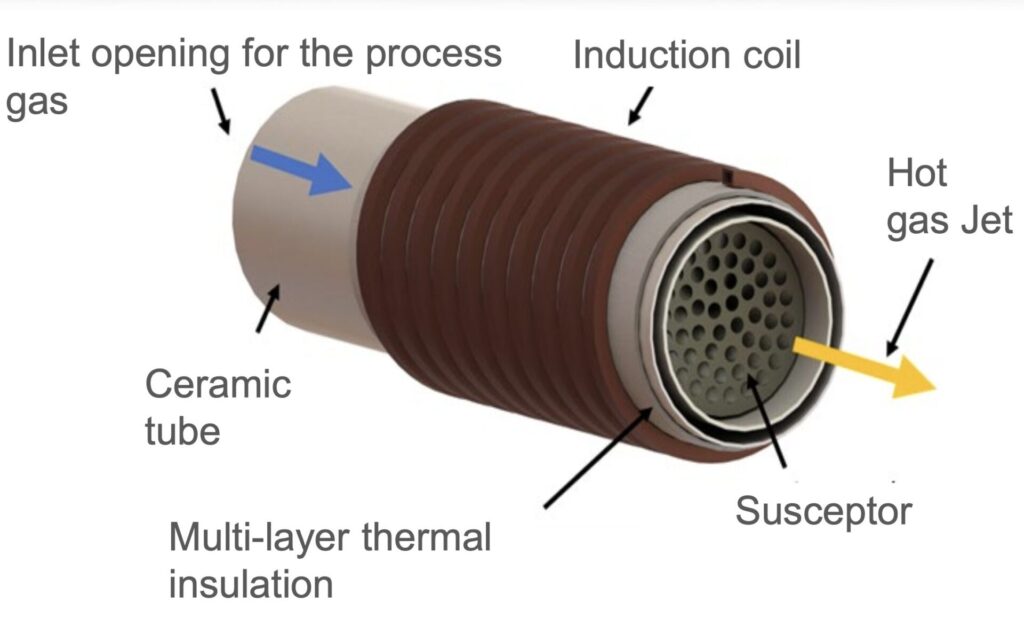
The system is based on an inductively heated metallic susceptor located inside a high-temperature-resistant, thermally insulated channel. A process gas flows through it, typically air, though inert gases or exhaust gases can also be used. The induction coil generates an electromagnetic field (Figure 2) that heats the susceptor without physical contact. The susceptor then transfers the heat to the gas flowing past it. The result is a hot gas jet with temperatures well above 1000°C (1830°F), fully replicating the thermal characteristics of a natural gas flame. Industrial test series have already achieved stable temperatures of up to 1400°C (2550°F) with response dynamics that surpasses conventional burners.
The technology transfers energy in two stages: first, the susceptor is heated via induction; then, the heat is transferred to the gas stream. This decoupled structure enables precise control of temperature, gas flow, and power input. The key lies in synchronizing the electrical power control with the gas flow to ensure a consistent and reproducible hot gas quality. The system responds to load changes within seconds, offering a level of controllability for high-temperature applications that has never been achieved before.
Technologically, it operates with minimal losses, as no exhaust gases are produced and the heat is transferred almost entirely to the process. By using closed gas circuits, the residual thermal energy of the exhaust stream can be reused without generating pollutants or releasing combustion residues into the atmosphere. This not only reduces energy consumption but also improves the process atmosphere, for example, through low-oxygen conditions that enable high-quality heat treatment.
Another key feature is its ability to integrate into existing systems. The design enables direct replacement of gas burners in many industrial applications without requiring fundamental modifications to the furnace architecture. This provides a fast and cost-effective path to decarbonizing existing installations.
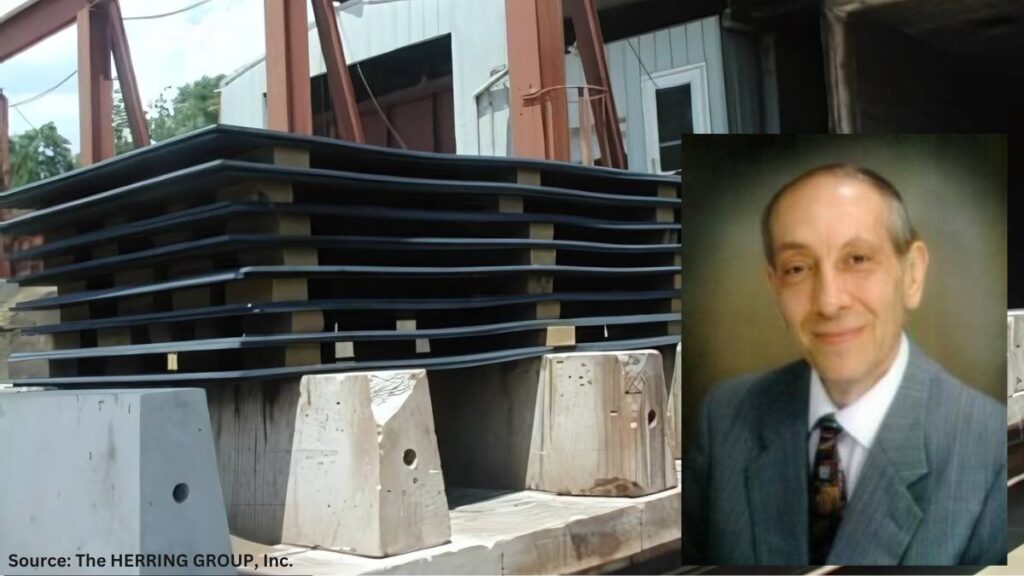
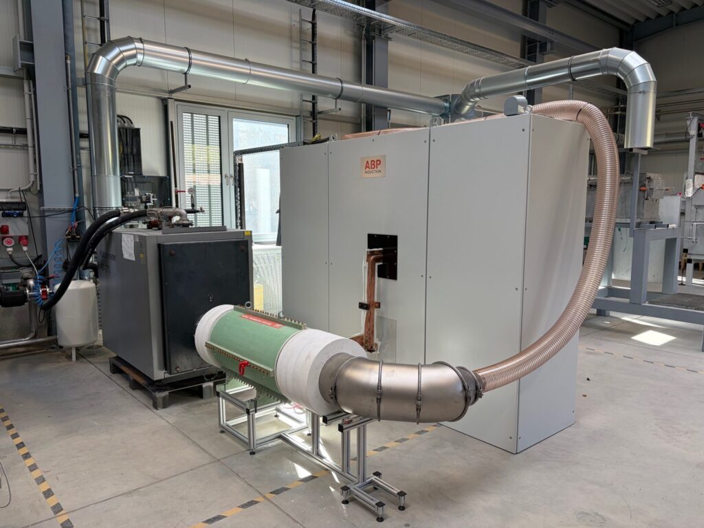
The concept was developed at the Foundry Institute of TU Freiberg. To bring the technology from the lab into real-world application, an alliance was formed: the university as the originator and development partner, Primetals as the system integrator, and ABP Induction for induction technology, contributing its insights in control systems, coil design, and power supply. Following successful lab trials with power levels between 10 and 35 kilowatts, an industrial demonstrator rated at 200 kilowatts is currently undergoing testing, serving as the foundation for market entry (Figure 3). The results demonstrate that the system is scalable — from compact applications to large-scale processes in the steel industry as well as glass, ceramics, and chemical.
The UHT Thermo Jet transfers the principle of induction to indirect process heat. While previous systems exclusively heated metallic workpieces directly, the new technology now enables controlled generation of hot gas streams — a decisive step toward full electrification of industrial heat supply. By combining efficiency, responsiveness, and sustainability, this solution paves the way toward a CO2-neutral future while ensuring cost-effective operation.
3 Stages: Technical Application Development
The development of hybrid heating systems follows a clear technological logic:
- In the short term, fossil-based systems are supplemented by complementary induction modules.
- In the medium term, they are replaced by electric heat sources, such as the UHT Thermo Jet.
- In the long term, they are fully electrified.
This evolution creates multiple advantages: first and foremost, a rapid entry into decarbonization through the retrofit of existing systems, resulting in lower operating costs due to reduced gas consumption and decreased maintenance requirements. This also leads to an increase in product quality thanks to precise temperature control. Companies also stand to benefit from the energy transition in the market, with long-term supply security, as electricity from renewable sources can be generated locally.
At the same time, new requirements are emerging for control and integration. Electric heating systems respond instantly to grid fluctuations and can be integrated into digital energy management systems. This makes it possible to optimize load profiles, adapt production processes flexibly to energy availability, and manage energy consumption with full transparency — a key milestone on the path to climate-neutral industrial production.
The ecological impact of hybrid heating systems is thus directly measurable. By partially replacing fossil burners, CO2 emissions can be reduced significantly. At the same time, nitrogen oxide and particulate emissions, which are typically generated during combustion, are reduced.
The economic picture is similar; while the investment costs for electric systems are higher, operating costs decrease due to lower gas consumption and improved energy efficiency. In addition, expenses for emission certificates, burner maintenance, and exhaust gas treatment are eliminated. In many cases, the investment pays off within a few years, especially when funding programs for the decarbonization of industrial processes are utilized.
In addition, the resilience of production systems improves. Electrically operated systems are less dependent on geopolitical energy imports and can potentially be powered directly by locally generated green electricity or by synthetically produced energy (via power-to-X processes) in the future. New energy storage concepts will also play a role here.
Practical Considerations
There are four key megatrends in industry: digitalization, deglobalization, demographic change, and decarbonization. Electrification of process heat is a key area of action, following the three-stage logical flow to implement fully electric, CO2-free process heat solutions. This approach reflects the reality in many industrial enterprises, which, due to their investment cycles, cannot implement an immediate transition. Hybrid solutions provide the essential bridge — both technologically and economically.
Despite these innovations, it is clear that the transformation of industrial process heat will not happen overnight. It requires time, investment, and a high degree of technical integration. Nevertheless, the electrification of thermal processes is considered an indispensable component of industrial decarbonization.
Hybrid heating systems represent a key enabling technology in this context. They enable the gradual replacement of fossil fuels, increase efficiency, and open up new degrees of freedom in production control. With innovations such as the UHT Thermo Jet, the range of applications expands significantly — reaching into areas like process gases and high-temperature applications that were previously considered the domain of fossil combustion.
Hybrid technology does not mark the end, but rather the beginning of a new generation of industrial heating systems — efficient, flexible, and climate-neutral.
About The Authors:

Chief Technical Officer and Director System Business
ABP Induction
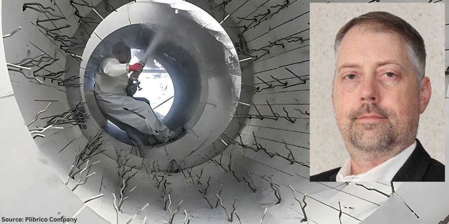
Dr.-Ing. Marco Rische is a highly qualified professional in induction heating systems technology with over 26 years of experience as the vice president of service, chief technical officer (CTO) and director system business with ABP Induction. He has demonstrated a deep technical understanding as a leader, leveraging his management and engineering background to solve complex technical and organizational challenges.

Application and Development Engineer
ABP Induction
Dr. Martin Ennen has studied electrical engineering and obtained his PhD in the field of electrical process engineering, with a focus on inductive heating processes. He has been working for three years at ABP as an application and development engineer. He is responsible for research and development work that entails numerical process simulation leveraging state-of-the-art FEM methods.
For more information: Contact Dr.-Ing. Marco Rische at Marco.rische@abpinduction.com and Dr. Martin Ennen at Martin.ennen@abpinduction.com.

Hybrid Heating Systems Unlock Heat Process Decarbonization Read More »