How do sintering parameters, especially the sintering atmosphere, affect the quality achievable from parts? Do you know what your three gas options are? Find out this and more, including an evaluation of some interesting solutions for your heat treating needs.
An excerpt:
"However vacuum furnaces operating with hydrogen require additional safety measures. For this reason, specific design solutions (such as double seals on all the furnace flanges) and software safeties are adopted. Despite the increased degree of complexity of the equipment and the higher process costs, vacuum furnaces operating with hydrogen over-pressure bring several advantages. . ."
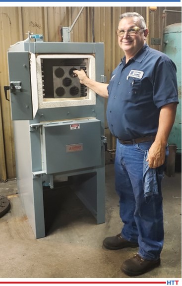
Kentucky Machine & Engineering, a machine repair business in Cadiz, Kentucky, upgrades their old gas fired furnace with a dual chamber furnace-over-oven unit. They will use the furnace to shorten their lead times on parts fabricated for their customers.
Kentucky Machine and Engineering Representative Standing Next to Lucifer Furnaces Unit Source: Lucifer Furnaces
Both chambers of the Lucifer Furnaces Red Devil Dual Chamber furnace-over-oven are 12”H x 14″W x 24″L; the upper chamber is programmed to heat to 2200°F while the lower oven reaches 1200°F. Dual Chamber furnaces allow a user to harden in the upper chamber then temper/draw in the lower convection oven. Both chambers are lined with 4.5″ multilayer lightweight firebrick insulation and mineral wool backup precision dry-fit to allow for thermal expansion while minimizing heat loss. Easy to replace heating elements simplify maintenance.
“By not having to outsource this piece of the process,” said AmyKuberski, CFO at Kentucky Machine & Engineering, “the increased size capability and the addition of the draw oven feature saves us a lot of extra time without having to be at the mercy of someone else’s schedule.” She added, “We were so pleased with the ease of installation to first use! Furnace was ready to go.”
Kentucky Machine & Engineering, Inc. have specialized in serving the steel, aluminum, automotive, and heavy equipment industries since 1971. From large machine repair or building new to quality fixtures, they strive to make their customer’s downtime as minimal as possible.
VIZ-Stal (NLMK Group) awarded an order for a decarburization and coating line (DCL) for its plant in Ekaterinburg, Russia to an international furnace provider for sustainable solutions in the metals industry. The company expects that the DCL will start production by the end of 2021.
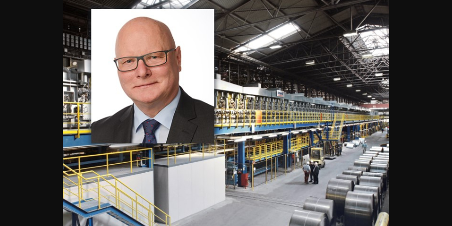
International heat treat plant provider with locations in North America, Tenova received the VIZ-Stal (NLMK Group) contract through its company Tenova LOI Thermprocess, an industrial furnace plant provider based in Essen. Through the cooperation between this competence center, which specializes in heat treatment furnaces, as well as Tenova Italimpianti, the competence center for strip processing, the new line will provide one of the important stages of grain-oriented (GO) electrical strip production. Steel final processing will be carried out at a newly-built plant located in India.
Peter Wendt Vice President Tenova LOI Thermprocess prozesswaerme.net
The contract includes the engineering, the supply and supervision services of mechanical and process equipment, the furnace system, and the related electrical, measuring, and control systems for the DCL.
"We are very pleased for this new order which confirms the reliability of the leading Tenova technology and underlines our strategic partnership with NLMK and VIZ-Stal," said Peter Wendt, vice president of Tenova LOI Thermprocess. "The NLMK Group is one of our most faithful clients with more than ten orders over the past fifteen years. The new DCL Line will ensure the highest surface and best magnetic properties required by the market."
"NLMK selected Tenova on the basis of the large number of references for similar heat treatment lines," explained Valery Shevelev, general director of Silicon Production at NLMK Group. “The short execution time is another important factor that led us to choose Tenova as partner for this project."
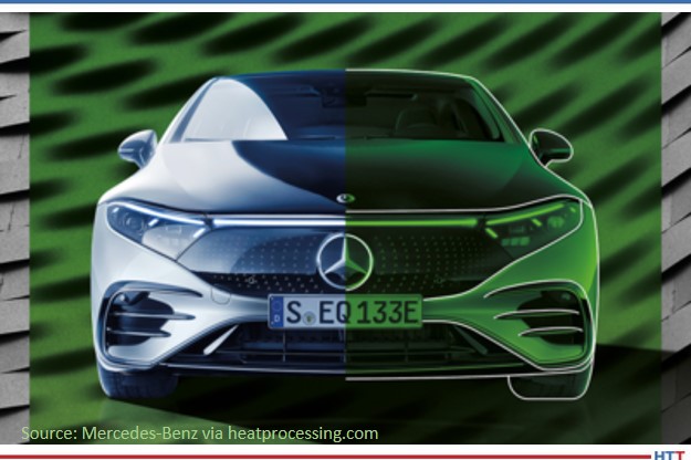
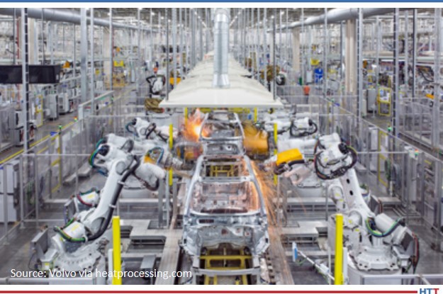
Welcome to another Technical Tuesday! Today, we look to our European information partner, heatprocessing, to share three technological shifts that are developing in steel and auto manufacturing. Specifically, these changes have to do with energy use through hydrogen and electricity.
Carbon-Neutral Pre-Material
“greentec steel is the ambitious plan developed by voestalpine to decarbonise steel production. Using a hybrid technology and electric arc furnaces would allow CO2 emissions to be reduced by around 30 % in a first step to 2030. The steel and technology Group’s long-term goal is to successively increase the share of green electricity and hydrogen used in the steel production process, together with tomorrow’s climate-neutral prematerials DRI and HBI, to achieve the goal of carbon-neutral steel production by 2050.”
“By using a new, innovate manufacturing process, the production of steel at the supplier level is CO2-free. By contrast, steel produced using a classic blast furnace, emits an average of more than 2 t of CO2 per t. In the new process, the supplier uses hydrogen and electricity from 100 % renewable energy sources instead of coking coal in steel production. The hydrogen serves as a reduction gas, which releases and binds the oxygen from the iron ore. Unlike the use of coking coal, this does not produce CO2, but water. The supplier uses electricity from 100 % renewable sources for the energy requirements generated in the manufacturing process.”
“For Volvo Cars, the CO2 emissions related to steel and iron production for its cars amount to around 35% in a traditionally powered car and 20 % in a fully electric car of the total CO2 emissions from the material and production of the components going into the car.
“SSAB aims to reduce Sweden’s CO2 emissions by 10 % and those in Finland by 7%, through HYBRIT technology, using hydrogen produced from water and fossil-free electricity instead of coking coal.”
Wherever you are, whenever you are, we hope you are enjoying a beautiful weekend to celebrate the ideals of freedom and liberty that were introduced at the independence of the United States! Wishing you and yours happy celebrations, and we’ll see you on Tuesday!
Heat TreatToday’s 40 Under 40 was created to bring recognition to young professionals in the industry, giving names, faces, and words to the rising generation of industry professionals. In this article, released in the final nomination period for Heat TreatToday’s 40 Under 40 Class of 2021, we caught up with exemplary classmates from 2020 to see what they have been up to since being recognized in September 2020.
Alberto Cantú VP Combustion, Control and Services Nutec Bickley
Alberto Cantú
"I’ve been working from home for the past year, which in my case means that I am saving 2 hours of commute time every day! That’s not only good for the environment but also for my pocket ?.
"With this 'extra time,' I decided I wanted to read more, so I subscribed to the Harvard Business Review magazine, which has been very helpful for work. But perhaps the most interesting thing I’ve read over the past year is a book by Dale Carnegie How to win friends and influence people. I know it’s a classic but I was very reluctant to read it because it felt like a cheesy self-help book (which I am not a fan of), but I have to say it has timeless advice."
Ellen Conway Merrill Vice President DELTA H TECHNOLOGIES, LLC
Ellen Conway Merrill
"The pandemic certainly presented its share of challenges, but it’s also been incredible to witness the strides being made across the industry in such a short matter of time.
"They say necessity is the mother of invention and many businesses across the globe, including DELTA H, have embraced the opportunity to think differently and creatively to give both our employees and clients some semblance of normality and connectiveness.
"DELTA H is grateful to have come out of 2020 with a record year in revenue which could not have been done if it weren’t for the dedication of our team to push forward through uncharted waters and embrace change."
Jeff Opitz President and Owner CeraMaterials
.
Jeff Opitz
"Since my induction into the Heat Treat Today’s 2020 “40 under 40” class, CeraMaterials has been fortunate to enjoy a surge in new business and product development, which has been especially rewarding considering the challenging business environment we’ve been navigating since the onset of Covid.
"A few noteworthy achievements include:
Developing a new resin treatment for our line of carbon-carbon modular fixturing which reduces open porosity and enhances performance in oil quench and fuel vane applications.
Collaborating with several large aerospace entities to switch out graphite and alloy fixtures for carbon-carbon fixtures, resulting in increased throughput and tooling longevity.
Conducting a national rollout of carbon composite and graphite insulation products with McMaster-Carr, achieving a 100% fulfillment rating.
"Additionally, we have a new production line up and running for our signature “tight weave” carbon cordage, available in 24K and 36K weave patters, outgassed to 2200C. We’re working with key players in the “hypersonic” space, and are in the process of obtaining full ITAR certification to help our business reach new heights! We’ve also invested in our team by hiring a new digital marketing manager and have added a new member to our shipping and receiving department to ensure our customers are receiving undamaged material in a timely manner.
"I’m beyond grateful to our loyal customers and suppliers, as well as our new business partners who allow us to continue growing and serving the global heat treat market."
Esau Zamorano Manufacturing and Heat Treating Project Engineer Eaton Hydraulics
Esau Zamorano
1. Just a few weeks ago, the certification for EATON Hydraulics was obtained as a plant under the ISO 9001: 2015 system.
2. Preparing for a conversion from EATON Hydraulics to the Danfoss culture and business system.
3. Developing new projects to minimize the risk of operation in batch-type furnaces with the add of safety devices in the furnaces.
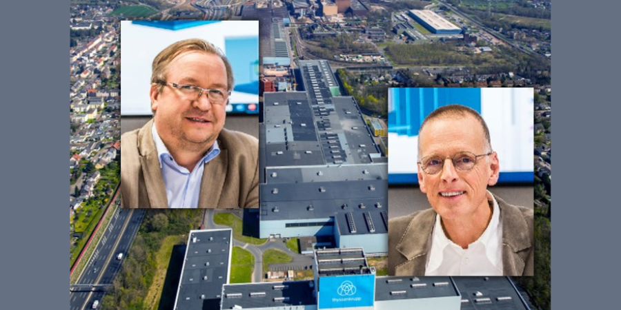
thyssenkupp Steel Europe will receive more than 250 new recuperative burners. These are designated for single ended radiant tubes (I-tubes) and W-Type radiant tubes. Final installation will be at FBA 7 of thyssenkrupp Steel Europe, Bochum (Germany), and delivery of the new combustion system will take place at the end of 2021. Commissioning is scheduled for the first quarter of 2022.
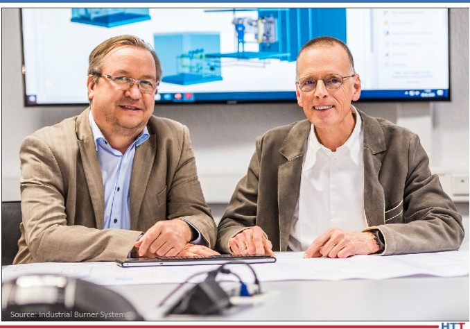
Tenova LOI Thermprocess placed the order and is part of a wider modernization project of a continuous galvanizing line at thyssenkrupp Steel Europe. The new combustion system, provided by German based burner manufacturer IBS Industrial Burner Systems, meets the highest requirements by targeting NOx-emissions lower than 140 mg/Nm³ @3%O2 – reference at target strip temperatures above 1652°F (900°C).
Thomas Wolf and Bernd Machovsky Managing Partners IBS Industrial Burner Systems GmbH
“This order is the latest of numerous appreciations of our efforts to provide state-of-the-art combustion systems for our customers,” states Bernd Machovsky, managing partner of IBS. His co-partner, Thomas Wolf, emphasizes, “Our ambition [. . .] is to provide environmentally sound and energy efficient solutions for all kinds of continuous strip lines, no matter if W-, double-P or I-Radiant Tube fired.”
With their LOOPFIRE®-technology, the burner manufacturer is able to achieve very low NOx-emissions simultaneously with highest thermal efficiencies of W-Type radiant tube burners, even when burning gases such as Coke Oven Gas (COG) and Coke-Oven / Blast-Furnace (COG/BFG) Mixed Gas.
Michael Lister Director of Sales - North America Consarc Corporation
The Doncasters Group recently ordered a vacuum furnace for their Doncasters Southern Tool facility in Oxford, Alabama. The order includes startup and installation with delivery scheduled before the end of 2021.
The new 300-pound Consarc vacuum precision investment casting (VPIC) furnace is equipped with high vacuum capabilities, controls, and increased automation with Teach Pour and other features that will give this furnace exceptionally high productivity for Doncasters Group.
The company is an international manufacturer of high-precision engineering components, designed to operate in the most demanding conditions. They serve the world’s leading OEMs in the aerospace, industrial gas turbine, and specialist automotive markets.
This order represents the 16th VPIC ordered from Consarc for delivery in North America in the last 24 months. Globally, the supplier has received 30 orders for this type of equipment in the same time frame.
"The recent strength in obtaining new orders for this product line is a testament to a customer centric philosophy we have at Consarc," said Michael Lister, director of Sales – North America at Consarc Corporation. "Our clients are sophisticated process owners who are well versed in the equipment and have demanding specifications placed on them by their own customers. Our collaborative approach in design, both before and after the order, is why customers trust [us] with these high value projects. We are able to understand their current problems and engineer long term solutions to mitigate those issues."
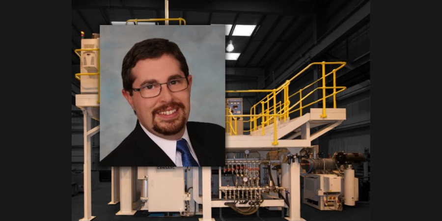
"A compressive surface stress can benefit bend fatigue performance by reducing the mean stress experienced during service, effectively offsetting the tensile stress generated by the cyclic loading conditions." In this Technical Tuesday by Justin Sims of DANTE Solutions, learn how a simulation program, funded by the U.S. Army, modeled the method of Intensive Quenching®.
This article covers Phase 2 of the project, a follow up to an article that was previously featured on Heat TreatToday. Check out more original content articles in this digital edition or other editions here.
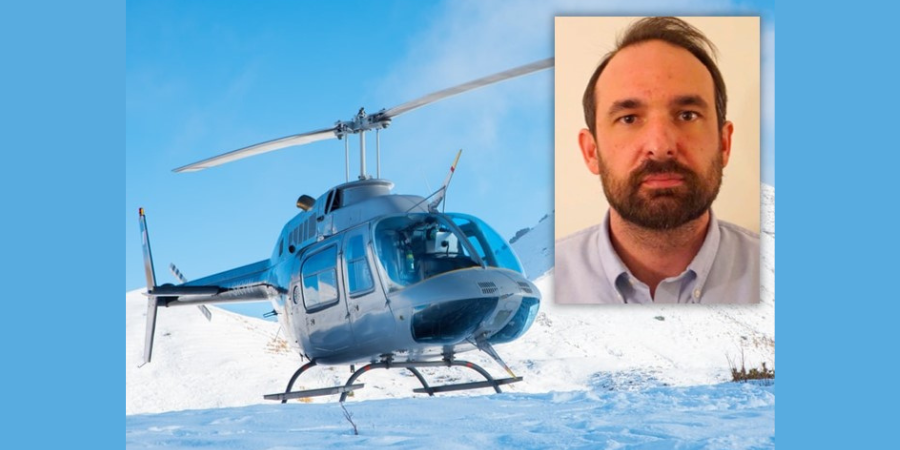
Justin Sims Lead Engineer DANTE Solutions
Helicopter powertrain gearing can be subjected to tremendous loads during service. The high tensile loads experienced in the root of the gear tooth, combined with the cyclic loading conditions inherent in gear operation, can lead to cyclic bend fatigue failures. To improve cyclic bend fatigue performance, low alloy steels are often carburized and quenched. The combination of a high carbon case and low carbon core leads to increased strength and hardness in the carburized case, while maintaining a tough core. In this manner, the case resists wear and can carry a high load without fracture, while the core is able to absorb the energy imparted to it during operation. Besides the increased strength and hardness, the addition of carbon creates a chemical gradient from the surface of the component towards the core. The carbon gradient creates delayed martensite transformations, relative to the low carbon in the core, and is responsible for imparting residual compressive surface stress. A compressive surface stress can benefit bend fatigue performance by reducing the mean stress experienced during service, effectively offsetting the tensile stress generated by the cyclic loading condition
Since the timing of the transformation to martensite is the main driver in the generation of compressive residual surface stresses, it is possible, to some extent, to control the magnitude of the surface stress by changing the quenching process. Historically, transmission gears have been carburized and quenched in oil. However, as more and more attention is paid to improving part performance through processing techniques, other forms of quenching have become available that show promise in increasing surface compressive stresses, and thereby improving bend fatigue performance. Of particular interest, is a quenching method which utilizes high pressure, high velocity water to quench parts.
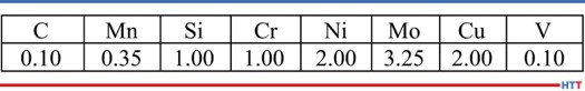
Table 1. Pyrowear 53 nominal chemistry.
Known as Intensive Quenching®, the method was developed by Dr. Nikolai Kobasko as an alternative means of quenching components to achieve deep residual surface compression and improve bend fatigue performance.1–3
The technology works by inducing a large temperature gradient from the surface to the core of the component. In non-carburized components, the process has been shown to provide an extremely rapid and uniform transformation to martensite in the surface layers, while the core remains austenitic. This creates a hard shell, under extreme compression. As the part continues to cool, the surface is pulled into an even deeper state of compression. As the core transforms, some compression is lost due to the expanding core, but the compression that remains is generally greater than that achieved by oil quenching.4–7
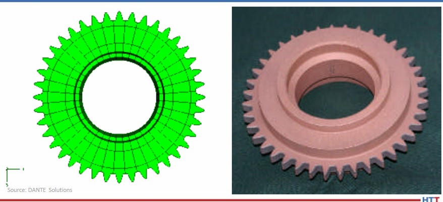
Figure 1. Gear CAD model (left) and actual test gear (right).
To evaluate the possibility of improving bend fatigue of helicopter transmission gears, a program was conceived to compare the bend fatigue performance of carburized gears quenched in oil versus carburized gears quenched using the Intensive Quenching process. Funded by the US Army, the project was comprised of two phases. Phase 1, described in a previous Heat Treat Today article, was a proof-of-concept phase, designed to prove that intensively quenched components could outperform oil quenched components in high cycle bend fatigue testing. Phase 2 then moved to actual transmission gear testing. DANTE heat treatment simulation was used extensively throughout the project to guide processing decisions and understand the mechanisms responsible for improved bend fatigue performance though the creation of residual surface compression. This article will examine Phase 2 of the project.
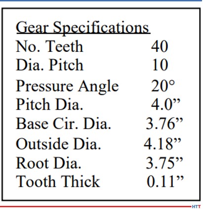
Table 2. Test gear specifications.
Pyrowear 53 was the material of choice for the project, as it is used extensively in helicopter power transmission gearing. Table 1 lists the nominal alloy chemistry for Pyrowear 53, which is a low-carbon, carburizing grade of steel. Figure 1 shows a CAD model of the test gear (left) and a picture of an actual test gear (right); the actual test gear is copper plated to selectively carburize only the gear teeth. The gears were carburized as one batch, and then hardened and tempered to a tooth surface hardness of 59 HRC and a core hardness of 42 HRC. An oil quenching process was used to harden half of the gears and an Intensive Quenching process was used to harden the other half of the gears. Table 2 lists the dimensional specifications of the gear.
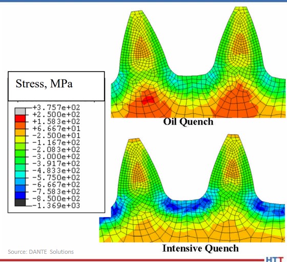
One benefit of using the Intensive Quenching process over a conventional oil quenching process is the development of high residual surface compression. Compressive surface stresses benefit fatigue performance by offsetting any tensile stress generated during loading, effectively reducing, or eliminating, the tensile load experienced by the material. Figure 2 compares the residual stress predicted by DANTE for the test gear subjected to an oil quenching process (top) and an Intensive Quenching process (bottom). It is clear that the Intensive Quenching process induces a greater magnitude of compression in the area of the tooth root, which is the location of most gear bending fatigue failures. The residual stresses present in the tooth flank appear equivalent between the two quenching processes, but the oil quenched component has higher tensile stresses under the carbon case. This could lead to problems should any inclusions or material defects be present in that location.
Figure 2. Residual stress prediction for test gear, comparing oil quench and Intensive Quench.
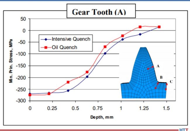
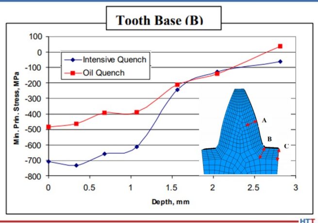
Figures 3 – 5 compare the residual stress profiles of the two gears at three gear tooth locations: flank, root-fillet, and root, respectively. The residual stress profiles for the two processes at the tooth flank, shown in Figure 3, are equivalent, as inferred from the contour plots shown in Figure 2. Both quenching processes generate a surface compressive stress of 275 MPa on the tooth flank. However, the residual stress profiles in the root area of the gear vary greatly between the two processes. Figure 4 shows the residual stress profile at the root-fillet, which is the location of the highest tensile stress during gear service. At this location, the rapid surface cooling afforded by the Intensive Quenching processes creates a large temperature gradient from the surface to the core, allowing more thermal shrinkage to occur after the surface transforms to martensite. The additional thermal shrinkage, combined with the concave geometry of the gear root area, creates additional compressive stresses in this area.
Figure 3. Residual stress versus depth prediction for test gear at point A, comparing oil quench and Intensive Quench.
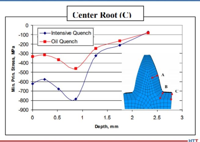
Figure 4 shows that the Intensive Quenching process generated a compressive stress of 700 MPa on the surface of the root-fillet, while the oil quenched gear produced a 500 MPa compressive surface stress in this location. The intensively quenched gear also has a deeper layer of high compression, not rising above 600 MPa compression until after 1 mm below the surface. Figure 5 shows a similar trend for the root, but with an even larger difference between the two quenching processes, since the geometry is even more concave at this location. Again, the gear subjected to the Intensive Quenching process has high compression up to 1 mm under the surface and a compressive surface stress magnitude 300 MPa higher than the oil quenched gear at the root location. The modeling results indicate that the intensively quenched gears should outperform the oil quenched gears in bend fatigue given the increased surface compressive stress present.
Figure 4. Residual stress versus depth prediction for test gear at point B, comparing oil quench and Intensive Quench.
Figure 5. Residual stress versus depth prediction for test gear at point C, comparing oil quench and Intensive Quench.
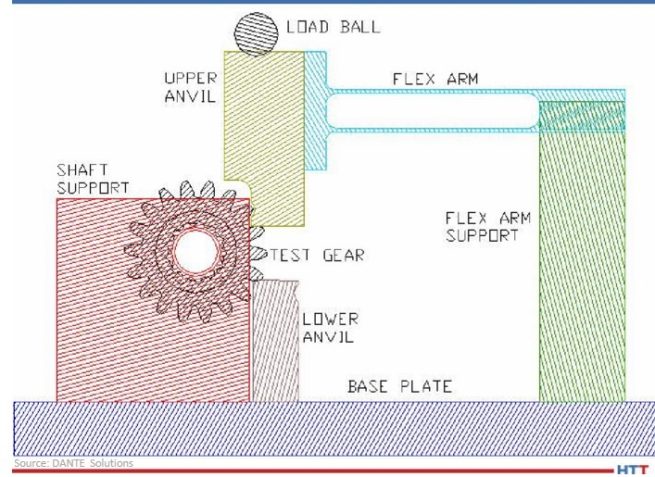
All of the hardened gears were tested at the Gear Research Institute, located at Pennsylvania State University in State College, PA, using a servo-hydraulic testing machine with a specially designed fixture to apply a cyclic bending load to two teeth. A schematic of the fixture is shown in Figure 6. A load ratio of 0.1 was used for all fatigue tests to ensure the gear did not slip during testing by having a constant tensile load applied. The fatigue test was considered successful, defined as a runout, if the gear completed 107 cycles given a certain maximum load. The maximum bending stress, calculated for a stress-free initial condition, was used to compare the two processes.
Figure 6. Schematic of fatigue testing apparatus.
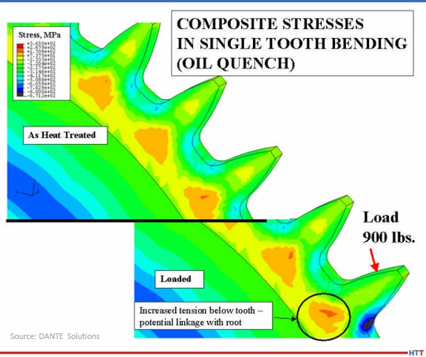
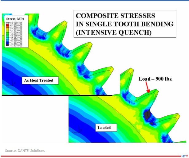
As previously mentioned, the effect of residual compressive stresses during tensile bend fatigue is to offset the tensile stress generated by the load. Figure 7 shows a DANTE model of the test gear subjected to oil quenching showing the residual stress from heat treatment (top) and the stress redistribution during the application of a 900 lb. load (bottom). Figure 8 shows the same conditions for the test gear subjected to the Intensive Quenching process. As can be seen from the two figures, in which the legend ranges are the same, there is substantially more compressive stress remaining in the root-fillet area of the gear subjected to the Intensive Quenching process when the load is applied. This means the effective stress experienced by the intensively quenched gear is less than that of the oil quenched gear, given an identical load.
Figure 7. Stress predictions for the oil quenched gear, showing the residual stress from heat treatment (top) and the stress change when a 900 lb. load is applied (bottom).
Figure 8. Stress predictions for the Intensive Quenched gear, showing the residual stress from heat treatment (top) and the stress change when a 900 lb. load is applied (bottom).
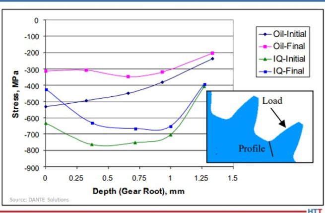
Figure 9 shows the residual stress profile from the surface at the root-fillet for both processes, in the unloaded and loaded conditions. From the plot, a load of 900 lb. generates a tensile stress of approximately 200 MPa, which is offset by the compressive residual stresses. With a 900 lb. load, neither gear sees any tensile stresses during loading, and thus, should runout during fatigue testing.
Figure 9. Comparison of predicted stresses versus depth for the oil quench and Intensive Quench gears in the unloaded (Initial) and loaded (Final) state.
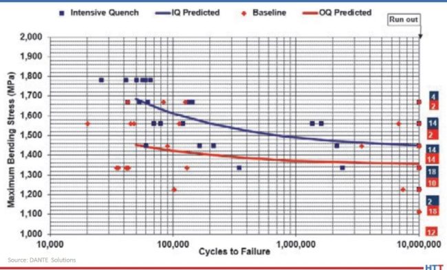
Figure 10 shows the results of the fatigue testing. As expected, the gears subjected to the Intensive Quenching process have an increase in fatigue performance. The endurance limit of the intensively quenched gears is approximately equal to the difference in surface compression, though additional tests should be conducted to confirm this. Regardless, increasing the magnitude of surface compression through a process change can significantly improve fatigue performance of power transmission gearing.
Figure 10. S-N curves for the oil quench and Intensive Quench gears tested.
In conclusion, achieving higher residual surface compressive stresses during hardening of a carburized power transmission gear by way of a process change was shown to improve bend fatigue performance. This was confirmed by the company's simulations, which showed a significant increase in compressive surface and near-surface stresses when the gear was quenched using the Intensive Quenching process, as opposed to an oil quench. The cause of the increased compression was determined from simulations to be due to the combination of martensite formation in the surface layers of the gear and the accompanying thermal shrinkage of the austenitic core, which draws concave geometric features, such as a gear tooth root, into a higher state of compression. The large temperature gradient induced during the Intensive Quenching process is necessary to produce these conditions. Physical fatigue testing confirmed the simulation results, showing a significant improvement in fatigue performance for the gears quenched using the Intensive Quenching process. Accurate process simulation pointed to a heat treatment process change that could be used to achieve increased power density through a transmission as opposed to more expensive and time-consuming design changes.
N. I. Kobasko and V. S. Morganyuk, “Numerical Study of Phase Changes, Current and Residual Stresses in Quenching Parts of Complex Configuration,” Proceedings of the 4th International Congress on Heat Treatment of Materials, Berlin, Germany, 1 (1985), 465-486.
N. I. Kobasko, “Intensive Steel Quenching Methods. Theory and Technology of Quenching”, SpringerVerlag, New York, N.Y., 1992, 367-389.
N. I. Kobasko, “Method of Overcoming Self Deformation and Cracking During Quenching of Metal Parts,” Metallovedenie and Termicheskay Obrabotka Metallov (in Russian), 4 (1975), 12-16.
M. Hernandez et al., Residual Stress Measurements in Forced Convective Quenched Steel Bars by Means of Neutron Diffraction”, Proceedings of the 2nd International Conference on Quenching and the Control of Distortion, ASM, (1996), 203-214.
M. A. Aronov, N. I. Kobasko, J. A. Powell, J. F. Wallace, and D. Schwam, “Practical Application of the Intensive Quenching Technology for Steel Parts,” Industrial Heating Magazine, April 1999, 59-63.
A. M. Freborg, B. L. Ferguson, M. A. Aronov, N. I. Kobasko, and J. A. Powell, Intensive Quenching Theory and Application for Imparting High Residual Surface Compressive Stresses in Pressure Vessel Components,” Journal of Pressure Vessel Technology, 125 (2003), 188-194.
B. L. Ferguson, A. M. Freborg, and G. J. Petrus, “Comparison of Quenching Processes for Hardening a Coil Spring,” Advances in Surface Engineering, Metallurgy, Finishing and Wear, SAE (01) 1373, (2002).
About the Author: Justin Sims has been with DANTE Solutions for eight years and is an excellent analyst and expert modeler of steel heat treat processes using the company's software. His project work includes development, execution, and analysis of carburization, nitriding, and quench hardening simulations. For more information, contact Justin at justin.sims@dante-solutions.com.
The Mint of Egypt which manufactures both circulation and numismatic coin will receive a vacuum heat treat furnace. The furnace will be used to heat treat circulation and numismatic coin, embossing dies, medals, and special orders. This furnace to the Mint of Egypt is the first furnace provided by the furnace manufacturer to the country of Egypt.
The Mint of Egypt was established in 1950. After 70 years of operation, the first Egyptian Museum of Circulating Coins was created at the mint. It displays a rare collection of special coins representing important historic figures and events, such as the construction of the Suez Canal and the Aswan High Dam. The Vector furnace will be used by the Mint of Egypt mostly for producing collection seals.
"We needed equipment that would significantly increase our production capacity," commented General / HossamKhedr, head of Egyptian Mint Authority, "With heat treatment in the vacuum furnace, our embossing dies will provide the highest possible quality and the durability that is important for the customers. Mints are very special companies. The ban on carrying embossing dies outside the mint prevents us from using commercial hardening plants. That is why it was extremely important to us that the equipment for upgrading our mint represented the highest quality."
Vector Vacuum Furnace by SECO/WARWICK
The Vector® vacuum furnace with 15 bar high-pressure gas quenching -- a product sold by North American SECO/VACUUM Technologies, which is the sister company to vacuum furnace supplier SECO/WARWICK -- is equipment that fits the operating performance requirements of mints. Furnaces with a graphite round heating chamber can be used for a majority of standard hardening, tempering, annealing, solution heat treating and brazing processes.
In the mint industry, these vacuum furnaces are popular as they ensure powerful, uniform gas cooling, which guarantees the high hardness and durability of mint tools. The perfect quality of mint punches and other products is ensured by the very high purity vacuum atmosphere. The parameters of the equipment purchased by the Egyptian Mint are very similar to the solutions delivered by SECO/WARWICK last year to the Mint of Poland — one of the most technologically advanced mints in the world. Some of the equipment installed by the Polish supplier has been operated by this customer for over 9 years.
Maciej Korecki Vice President of the Vacuum Furnace Segment SECO/WARWICK (source: SECO/WARWICK)
"Mints are very demanding customers. They manufacture high quality products that requires perfect details and production repeatability. Collectors, who are the customers of mints, expect the highest care, durability and quality of the finished products," said Maciej Korecki, Vice-President, Vacuum Furnace Segment, SECO/WARWICK Group. "This makes us even more happy that our flagship product — the Vector vacuum furnace — will be installed in another national mint."
Worldwide, there are 70 national mints and several dozen privately-owned mints, manufacturing almost 800 various coin denominations. The oldest mint in the world that has been continuously operated since 864 and the eighth oldest company in the world is Monnaie de Paris in France. The British Royal Mint is the tenth oldest company in the world, established in 886. National Mints provide the official currency for their home countries. They need to comply with rigorous standards that guarantees the weight, purity, and face value of the bullion they produce. This guarantee enables the bullion products manufactured by the state to enjoy a global reputation as the ideal source for investment in high-quality noble metals.


 Source: TAV VACUUM FURNACES