Technical Tuesday

Ask the Heat Treat Doctor®: How Does One Determine Which Quench Medium To Use?

The Heat Treat Doctor® has returned to offer sage advice to Heat Treat Today readers and to answer your questions about heat treating, brazing, sintering, and other types of thermal treatments as well as questions on metallurgy, equipment, and process-related issues.

The Heat Treat Doctor® ha vuelto para ofrecer sabios consejos a los lectores de Heat Treat Today y para responder a suspreguntas sobre el tratamiento térmico, brazing, sinterizado y otros tipos de procesamiento térmico, así como preguntassobre metalurgia, equipos y problemasrelacionados con los procesos.

This article was originally published in Heat Treat Today‘s September 2024 People of Heat Treat print edition.

To read the article in Spanish, click here.


Quenching is a critical step in the heat treating process. And while there are often several choices available to the heat treater, a delicate balance exists between what is available to us and how we can optimize its performance characteristics to meet our client’s requirements/specifications. Material, part design (geometry), pre-and post-manufacturing requirements, loading, allowable dimensional change (i.e., distortion), and the process itself must be taken into careful consideration. Let’s learn more.

Quenchants — A Brief Overview

Today’s quenchants offer a broad and, in some instances, overlapping range of capabilities. But at a fundamental level, the role of a quenchant is to extract heat from the part surface to meet a specified critical cooling rate and achieve the desired microstructure in the component part necessary to achieve the required mechanical and physical properties. In hardening of steels, for example, one must miss the “nose” of the time-temperature transformation (TTT) curve if the desired end-result is a martensitic (or bainitic) microstructure. By contrast, the cooling rate for a normalizing process requires cooling in “still air” — a term that is often misunderstood and which we will cover in a future discussion.

Figure 1. Common types of quenchants and their effect on distortion (See Reference 1)

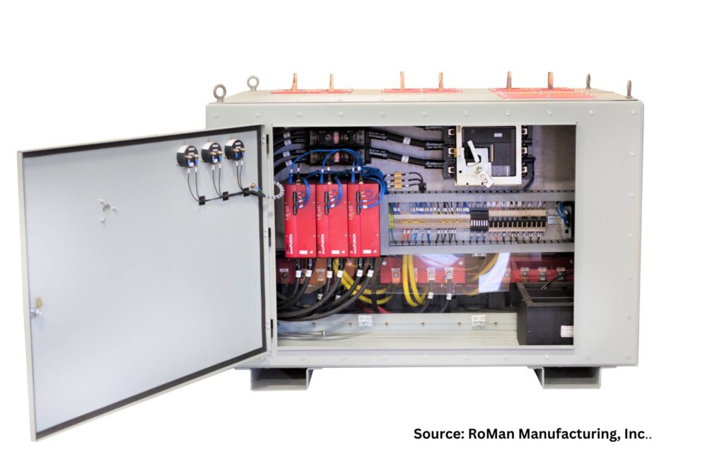
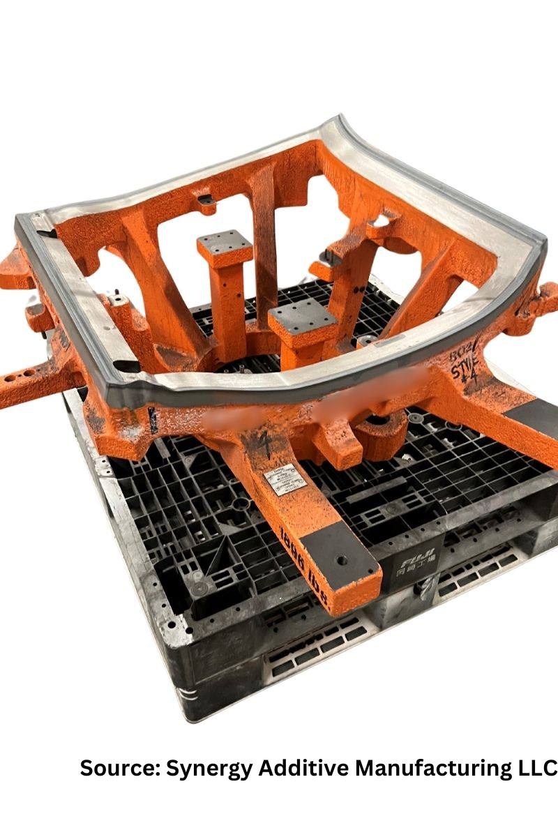
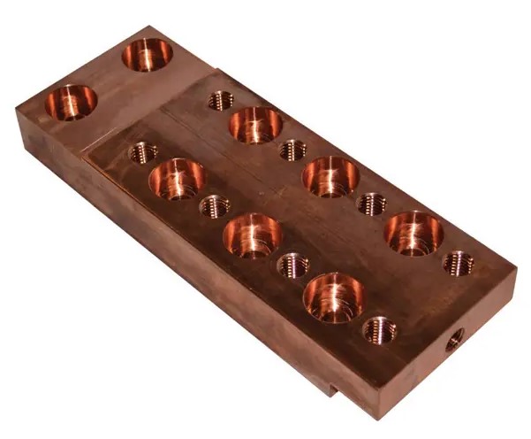
However, a quenchant (Figure 1) is more than just its cooling rate. Quenchants should be stable over their service life, especially with respect to degradation (e.g., oxidation), be safe, be easy to service and maintain, have a high vaporization point, ideally not interact with the part surface, be used within their optimum performance range, have long life, be easily removed by cleaning after quenching, and be cost effective.

As a very broad-based characterization, quenchants can be divided into the following general categories:

  • Liquid quenchants (e.g., water-based, oils, polymers, molten salts, and molten metals)
  • Gaseous quenchants (e.g., air, nitrogen, argon, hydrogen, steam, carbon dioxide, sulphur dioxide, reducing gases, protective atmospheres — synthetic or generated, high-pressure gases)
  • Solid quenchants (e.g., water-cooled dies, plates, powders)
  • Mixed media quenchants (e.g., mist or fog quenching, fluidized beds)
Figure 2. Ishikawa (aka fishbone) diagram of quenching variables (See Reference 1)

Selection of the Optimal Quench Medium

Contact us with your Reader Feedback!

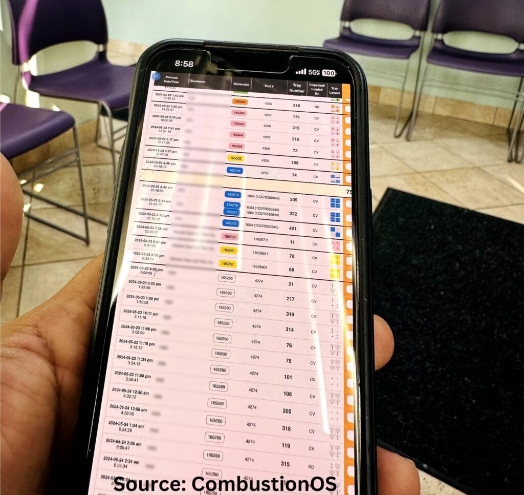
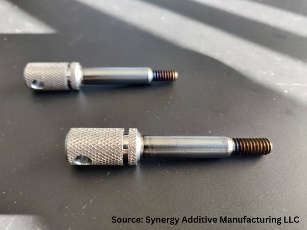
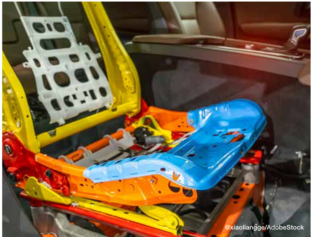
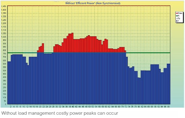
Various factors must be taken into consideration when selecting the best quench medium. The following are some of the important considerations when selecting the proper quench medium (Figure 2):

  • Material — chemistry, hardenability, form (e.g., bar, plate, forging, casting), type (e.g., wrought, powder metal), and cleanliness to name a few
  • Part geometry/design — shape, size, weight, complexity
  • Mill or preheat treatment condition — annealed, normalized, pre-hardened, stress-relieved
  • Stress state — the cumulative effect of both mill operations and customer manufacturing operations prior to heat treatment
  • Loading — baskets (alloy, C/C composites, graphite plates, etc.)
  • Process parameters — temperature, time, preheating
  • Equipment selection — is it optimal or simply adequate for the job?
  • Quench medium(s) available — their limitations as well as their advantages

It is important to talk briefly here about two aspects of the quench medium selection process. First, note the difference between hardness and hardenability (which we will discuss in more detail in the future). Heat treaters tend to focus on hardness (since we can easily measure it in our shops), but hardenability is a critical consideration in quench medium selection. Hardenability is a material property independent of cooling rate and dependent on chemical composition and grain size. When evaluated by hardness testing, hardenability is defined as the capacity of the material under a given set of heat treatment conditions to harden “in-depth.” In other words, hardenability is concerned with the “depth of hardening,” or the hardness profile obtained, not the ability to achieve a particular hardness value. When evaluated by microstructural techniques, hardenability is defined (for steels) as the capacity of the steel to transform partially or completely from austenite to a defined percentage of martensite.

Table 1. Average and instantaneous values of the heat transfer coefficient (See Reference 3)

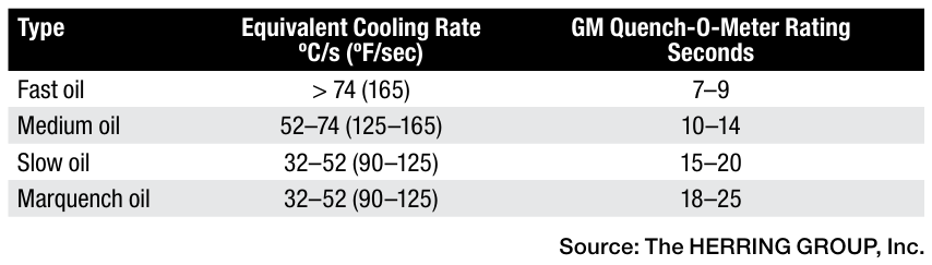
Second, one must be aware of both the average and instantaneous value of the heat transfer coefficient alpha of the quench medium. Although the maximum quenching “power” may be described by the instantaneous heat transfer coefficient, the average heat transfer coefficient (Table 1) provides a better relative comparison of the various quenching media since it represents the value of the heat transfer coefficient over the entire range of cooling (from the start to the end of quenching). It is important to remember that the ability to manage (not control) distortion is a delicate balancing act between uniform heat extraction and proper transformation.

A Common Example — Quench Oil Selection

Important factors to consider when selecting a quench oil, which hold true in a slightly modified form for most liquid quenchants, are: the type of quenchant (i.e., quench characteristics, cooling curve data — new and over time); quench speed (see Table 2); usage temperature; effective quench tank volume (i.e., the one gallon per pound of steel [8.4 L/kg] rule); and the client’s requirements.

Table 2. Classification of quench oils (See Reference 1)

Quench tank design factors also play an important role and involve the following:

  • Volume of oil in the quench tank
  • Number of agitators or pumps
  • Location of agitators
  • Type of agitators (fixed or variable speed)
  • Internal tank baffle arrangement (draft tubes, directional flow vanes, etc.)
  • Quench elevator design (i.e., flow restrictions)
  • Quenchant flow direction (up or down through the load)
  • Propeller size (diameter, clearance in draft tube)
  • Maximum (design) temperature rise of the oil after quenching
  • Height of the oil over the workload
  • Heat exchanger — type, size, heat removal rate (instantaneous BTU/minute)
  • Oil recovery time to setpoint

Finally, consideration must be given to factors such as: part mass; part geometry (e.g., thin and thick sections, sharp corners and holes, gear tooth profile/modulus, thread profile, etc.); part spacing in the load; effective flow velocity through the quench area (empty and with a load); stress state from prior (manufacturing) operations; post heat treat operations to be performed (if any); loading including the grids, baskets, and fixture (material and design); and the material (chemistry and hardenability).

Final Thoughts

Quenching, considered by many to be a complex and multi-faceted subject, is one heat treaters must constantly monitor and control. In future installments we will be discussing many of the individual aspects of quenching. What is important here is to recognize that done correctly, quenching
(in whatever form) will optimize a given heat treatment and help produce the highest quality parts demanded by the industries we serve.

References

Daniel Herring, Atmosphere Heat Treatment, Volume II: Atmospheres | Quenching | Testing (BNP Media Group, 2015).

Božidar Liščić et al., Quenching Theory and Technology, Second Edition (CRC Press, Taylor Francis Group, 2010).

Daniel Herring, “A Review of Gas Quenching from the Perspective of the Heat Transfer Coefficient,” Industrial Heating, February 2006.

About the Author

Dan Herring
“The Heat Treat Doctor”
The HERRING GROUP, Inc.

Dan Herring has been in the industry for over 50 years and has gained vast experience in fields that include materials
science, engineering, metallurgy, new product research, and many other areas. He is the author of six books and over
700 technical articles.

For more information: Contact Dan at dherring@heat-treat-doctor.com.

For more information about Dan’s books: see his page at the Heat Treat Store.


Find Heat Treating Products And Services When You Search On Heat Treat Buyers Guide.Com


Ask the Heat Treat Doctor®: How Does One Determine Which Quench Medium To Use? Read More »

Controlled Power Distribution Systems

Like most power systems, power control dates back to vacuum tube technology. Like radios, amplifiers, and other industrial equipment, the furnace market started using transistors as the technology evolved. Vacuum tubes were not generally balanced and contained poisonous elements and were phased out of usage in almost all industries. In this Technical Tuesday installment, guest columnist Stanley Rutkowski III, senior applications engineer at RoMan Manufacturing, Inc., distinguishes the different methods used to regulate power input to furnaces.

This informative piece was first released in Heat Treat Today’s August 2024 Automotive print edition.


An ERT/SCR power control
Source: RoMan Manufacturing, Inc.

In today’s furnace market, there are generally three primary types of control systems: VRT, SCR, and IGBT. Each of these control technologies employs different methods to regulate the power input to the furnace, which in turn generates the required heat. These control systems transfer the power from the plant power system to a transformer in line with the load (heating elements). Power is delivered to a plant in a three-phase system from the utility company. The least costly and highest power factor systems have a balanced load across the three phases during the operation of any furnace.

VRT (Variable Reactance Transformer)

A VRT incorporates a feedback mechanism to either increase or decrease the amount of DC injected into the controlling reactor in the system. This increases or decreases the amount of current in the system to control the heat in the furnace by comparing it to the scheduled setpoint. A VRT system can have the following configurations:

  • Single-phase power controller for single load applications
  • Scott-T three-phase power controller (this is a system that allows all three phases of the incoming power system to be utilized in a two-phase load application)
  • Three-phase power controller (in either a Delta or Wye configuration) for three zone load applications

SCR (Silicon Controlled Rectifier)

An SCR control system uses a pair of thyristors (gated diodes) to control the amount of power applied to the primary of a transformer. The SCR control delays the start of the waveform, and the control point is reset when the waveform crosses the zero line. An SCR system can have the following configurations:

  • Single-phase, phase-angle controlled for single load applications
  • Single-phase, zero-cross controlled for single load applications
  • Single-phase, on-load, tap-changing controlled (this incorporates multiple pairs of the thyristors together to lessen the losses of the SCR system)
  • Scott-T three-phase power controlled (this is a system that allows all three phases of the incoming power system to be utilized in a two-phase load application)
  • Three-phase, phase-angle controlled (in either a Delta or Wye configuration) for three zone load applications
  • Three-phase, zero-cross controlled (in either a Delta or Wye configuration) for three zone load applications

IGBT (Insulated-Gate Bipolar Transistor)

An IGBT power control
Source: RoMan Manufacturing, Inc.

An IGBT uses a diode bridge, capacitor, and switching transistors to control the amount of power applied to the primary of a transformer. The input frequency to the transformer is controlled by the switching transistors. The diode bridge is connected to the three-phase system allowing single, Scott-T (two zone), or three zone systems all to pull a balanced load across the three phases of the plant power system. A line reactor is incorporated to maximize the power factor in the system, minimizing the total power usage of the furnace. The IGBT system also uses a square wave into the transformer and a rectifier after the transformer to remove inductance out of the power delivery system to reduce costs of cables, breakers, and other components in the total package.

About the Author:

Stanley F. Rutkowski III
Senior Applications Engineer
RoMan Manufacturing, Inc.

Stanley F. Rutkowski III is the senior applications engineer at RoMan Manufacturing, Inc., working on electrical energy savings in resistance heating applications. Stanley has worked at the company for 33 years with experience in welding, glass and furnace industries from R&D, design, and application standpoints. For more than 15 years, his focus has been on energy savings applications in industrial heating applications.

For more information: Contact Stanley at srutkowski@romanmfg.com.


Find Heat Treating Products and Services When You Search on Heat Treat Buyers Guide.com

Controlled Power Distribution Systems Read More »

Stainless Corrosion


I’m starting to see Cybertrucks out in the wild more, so I decided to talk about stainless corrosion for #MetallurgyMonday. (If you don’t know what #MetallurgyMonday is, it is a weekly educational post on metallurgy topics that I’ve been writing on LinkedIn for the past two years.)

First a little up front. I’m not a fan of the aesthetics of the Tesla Cybertruck. Plus, we need about twice the load capacity for our work purposes since Skuld actually uses our truck as a truck.

More to the point, stainless steel is not rust proof. It is corrosion resistant and will rust in a lot of circumstances. 

To understand why, we need to understand what prevents corrosion in the first place. The key elements are chromium and nickel. Chromium reacts with oxygen to create a thin layer of chromium oxide. This is on the surface and blocks further oxidizing of the underlying layers. Meanwhile, the nickel enhances the corrosion resistance. It also makes the material more formable and weldable.

The short story is that if the chromium oxide layer gets compromised, stainless steel will corrode.

Improper heat treating can also contribute to stress corrosion cracking.

Sarah Jordan
  1. Pitting corrosion: If you have a scratch or a pit, this can damage the protective film, and then corrosion begins. It’s worse in environments with chloride ions, such as seawater or pool water. Chlorides break down the passive layer, leading to rapid and severe corrosion in small areas.
  2. Crevice corrosion: This occurs when two objects come together, especially things like fasteners or where there is a gasket. Inside the crevice you will have a lack of oxygen. The lack of oxygen prevents the reformation of the protective chromium oxide layer. Once corrosion gets started, it can get very severe by propagating in the crevice.
  3. Stress corrosion cracking (SCC): Corrosion is made worse where there is a combined effect of tensile stress and a corrosive environment. It typically affects stainless steel used in structural applications that are exposed to chloride or sulfides. SCC can cause sudden and catastrophic failure of the metal structure.
  4. Galvanic corrosion: Galvanic corrosion happens when two metals are put together. One of them almost always wants to preferentially corrode. The one that corrodes is the one that is higher on the galvanic series. 
  5. Intergranular corrosion (IGC): Sometimes this is called intergranular attack (IGA). In this case, corrosion occurs preferentially at grain boundaries. This can occur in stainless if the grain boundaries get depleted of chromium because a minimum amount is needed to ensure the passive film can form to protect the metal. When this occurs, there can also be localized galvanic corrosion.
  6. Composition variation: If the composition has segregation, then there are some areas that have less of the corrosion-helping elements. And on top of that, galvanic corrosion can start happening within the material.

What does all of this have to do with heat treating? Improper heat treating can contribute to corrosion.

For instance, intergranular corrosion can be caused if the material is exposed to 842–1562°F (450–850°C) for too long as this will cause chromium carbide to form at the grain boundaries and deplete the chromium. This process is called “sensitization.” It is avoided by making sure quench rates are fast enough through the risky temperature range.

A somewhat similar situation can occur during heat treating if sigma phase forms in super duplex stainless steel. Sigma phase is an iron chromium phase which can also deplete the chromium.

Improper heat treating can also contribute to stress corrosion cracking. When material is quenched, it can cause residual stresses that, if not relieved, can become an issue.

Corrosion in stainless steel can often be traced to improper heat treatment. When stainless steel is heated between 842–1562°F (450–850°C), chromium carbides can form at the grain boundaries, depleting the surrounding areas of chromium and making them susceptible to corrosion.

All of this to say, things like the Cybertruck (or for that matter stainless fridges and appliances) can be prone to corrosion since they are exposed to a lot of abuse and aggressive environments. It is critical to ensure they are properly manufactured, including good heat treating practices. It is also critical to provide them with proper maintenance to keep the corrosion resistance and appearance lasting as long as possible.

About the Author:

Sarah Jordan
Founder & CEO
Skuld, LLC
Source: Author

Sarah Jordan is an accomplished metallurgical engineer and entrepreneur. She received a bachelor’s of science and master’s of science in this discipline from The Ohio State University and has been pursuing a PhD in Metallurgical Engineering from WPI. Skuld is a certified WOSB and EDWOSB startup focused on 3D printing, advanced manufacturing, and advanced materials.


For more information, contact Sarah at her LinkedIn profile: Sarah Jordan | LinkedIn.


Find Heat Treating Products And Services When You Search On Heat Treat Buyers Guide.Com

Stainless Corrosion Read More »

A New Era: Tracking Quality Digitally

What are advanced management systems and how does deep integrative system management software help automotive heat treaters improve processes while saving on time and unnecessary expenses? Explore the future of software technology for the management of heat treating operations in this Technical Tuesday by Sefi Grossman, founder and CEO of CombustionOS.


The heat treating industry is on the brink of a technological transformation. Just as the momentous adoption of websites and emails transformed the nature of work for manufacturers, the advanced software systems are thrusting us into a new era of simplicity, automation, and deep integrations.

This article explores how advanced systems — an application of ERP (enterprise resource planning) and MES (manufacturing execution systems) combined with the power of AI — is revolutionizing facility operations, enhancing quality, efficiency, and profitability.

What Are Advanced Systems?

Advanced systems simplify, streamline, and automate operations by lifting the data burden off of plant personnel. While most existing systems focus on the part inventory workflow, more advanced systems go beyond by directly integrating into the heat treat process to track at bin/tray/tree level.

This requires real-time scheduling control, barcode scanning, digitizing recipe and process (no more paper), and direct sensor/PLC integration. Because of its critical nature, an advanced system is most likely an on-premise and cloud “hybrid solution” that is not crippled by internet connectivity issues. This allows it to still utilize rapidly evolving cloud systems that provide external services like messaging, big data storage, and AI to name a few.

Precise Processing

Figure 1. CombustionOS developers spend extensive time with operators and plant managers to create interfaces that are intuitive and easy to use. Pictured is access to job data stats from a mobile device being used outside of the manufacturing plant.

Repeatable, accurate methods to ensure optimal time, temperature, and atmosphere of the decided heat treatment processes are possible with advanced systems.

Utilizing existing sensors and hardware interfaces, data is collected in short intervals, transformed into meaningful data formats, and stored in a database. Network technologies such as HTTP, Modbus, and other analog to AI technologies make this possible with minimum additional hardware. The data is managed locally on the facility network, and synchronized with cloud services for further processing, analysis, and long-term history storage.

With a close monitoring of all these variables, facilities can tighten acceptable specification ranges. Deep integration with equipment ensures that data flows seamlessly from sensors and devices to the central system.

This real-time data collection and processing enables facilities to monitor operations continuously and make informed decisions quickly. For example, integrating data from temperature sensors, pressure gauges, and other monitoring devices ensures that all critical parameters are tracked and managed effectively. Additionally, if a temperature reading deviates from the acceptable range, the system can immediately alert the relevant personnel, allowing them to take corrective action before it becomes a critical issue.

 In addition to quality assurance, integrated artificial intelligence tools optimize job scheduling. Unlike traditional date/time calendar methods, AI systems predict job completion times based on real-time process data. This is particularly useful for roller furnace setups, where continuous processing occurs, but it is also beneficial for batch furnaces. Optimized scheduling improves resource allocation and operational efficiency, ensuring that jobs are completed on time and to the required specifications. The difference between a “calculation algorithm” and AI is that, with AI, you do not have to pre-program it. It automatically learns and adjusts for known variability in your hardware and even the personnel that are operating the equipment.

Finally, the automation of these systems captures and records all necessary information accurately. This reduces the risk of non-compliance, improving the overall quality of the final product. For example, a Detroit-based heat treating facility reported that accessing real time data to ensure compliance with industry standards has allowed them to spend 40% less time on documentation tasks.

Figure 2. Having increased control over the process gives more peace of mind to operators that components perform as needed.

Alleviating Burden on Maintenance and Inventory

Predictive maintenance is one of the most significant applications of AI in the heat treating industry. Traditional maintenance schedules are often based on fixed intervals, which can lead to unnecessary downtime or unexpected failures. AI driven predictive maintenance, on the other hand, uses real-time data to determine the optimal times for maintenance activities. This approach not only reduces downtime but also extends the lifespan of equipment.

A Detroit-based heat treating facility implemented an AI-driven predictive maintenance system (PMs) and saw a 25% reduction in equipment downtime. By analyzing data from critical parts, inventory, process tracking history, and various sensors, the AI system could predict when components were likely to fail, allowing the maintenance team to inspect and address issues proactively beyond their standard PMs. This not only improved operational efficiency, but also saved significant costs associated with emergency repairs and unplanned downtime.

Additionally, the integration of QR codes for inventory and process tracking enables quick and accurate data entry compared to manual logging. For instance, when racking parts out of bins, operators can simply scan QR codes, which automatically update the system with the relevant information. This not only speeds up the process but also minimizes the chances of human error.

Reducing Operational Costs

The adoption of advanced ERP and MES systems has led to substantial cost savings for many facilities. These systems reduce operational costs through the implicit automated integrations that technologies like CombustionOS bring. Here are just a few ways that operational costs have been cut:

  • Decreasing shipping and receiving management from three to just one employee
  • Minimizing rework costs by timely process alerts
  • Reducing personnel by replacing constant manual oversight with accurate, digital tracking systems
  • Lowering administrative costs by utilizing a more efficient and accurate invoice automation platform

Case Study: A client reported comprehensive cost savings, including a 20% reduction in shipping and receiving time, fewer logistics and furnace operators needed, a 33% decrease in rework costs, a 15% savings in maintenance costs, and a 25% reduction in accounting overhead. These efficiencies translate into substantial payroll savings and improved profitability.

How To Implement

Figure 3. When racking parts out of bins, operators can simply scan QR codes, which automatically update the system with the relevant information.

One of the most significant advancements in heat treating technology is the deep integration with various equipment types. Unlike traditional ERP systems, which often lack true integration, advanced systems work backwards from equipment data, building ERP functionalities around this integration to ensure seamless and accurate data flow.

First, there are advanced systems that can handle data from both digital and analog sensors. So, for heat treaters who are juggling a variety of sensors and systems, looking for an integrative advanced system that has adaptability will ensure compatibility with existing equipment while keeping an eye on cost. Facilities can continue using their current equipment while benefiting from advanced monitoring and control capabilities.

Second, advanced ERP/MES systems can take collaboration with multiple vendors. Rather than uproot current systems and relationships, work with an advanced systems provider who is able to collaborate with other software and systems. Advanced ERP/MES systems provide comprehensive solutions that include deep equipment integration and full ERP functionalities. This approach reduces the complexity and cost of integration, ensuring that all components work together seamlessly.

Key Applications

Most operations in a heat treat department will benefit from advanced systems due to the time-saving automations that the system integrates. But many heat treaters are looking to adapt and integrate older systems and often more complex designs, like roller hearth furnaces. Here are some steps that experts will take to guide you through to make the digital integration smooth and effective:

  1. First, it is important to understand you don’t need to boil the ocean. Starting with a more advanced inventory tracking system that employs barcodes can set the underpinnings for a more integrated system while providing immediate benefits to your logistics.
  2. Then, it is also key to get a deep understanding of your current process and map out your operational workflow. Using a flowchart program helps
    visualize the process to make sure all stakeholders are on the same page.
  3. Some aspects of your current process are probably outdated (perhaps created by someone who is no longer at the company), while others are key to the core of how you operate. Understanding the difference is crucial to make sure you unlock potential automation without disturbing your core process and flow.
  4. You’ll then need to prepare every required form, document, chart etc. that you use in the operation. For process control, recipes, and lab testing, provide many parts/iterations to capture the complexity.
  5. Finally, take inventory of any existing digital systems you have adopted, like inventory tracking, spreadsheets, or custom software. The existing system
    network, including servers, Wi-Fi setup, and hardware (PCs, printers, scanners, etc.) will be utilized as much as possible in the transition to reduce the need to purchase and set up different equipment.

Conclusion

The future will require constant innovations and thoughtful leveraging of increasingly advanced systems. Unlike static, homegrown, or “pieced together” solutions, the most advanced systems are constantly updated with new features, ensuring they remain at the cutting edge of technology. Engaging directly with plant personnel to understand their needs and challenges allows systems like CombustionOS to evolve and improve continuously.

The heat treating industry is on the cusp of a technological transformation, driven by advancements in ERP, MES, and AI. These technologies offer the potential to enhance quality, efficiency, and profitability, making them essential for the future of manufacturing. By embracing automation, integrating advanced AI capabilities, and committing to continuous innovation, the industry can achieve new levels of operational excellence.

About the Author:

Sefi Grossman
Founder & CEO
CombustionOS
Source: Author

Sefi Grossman has been at the forefront of technology revolutions for the past two decades and has been leading the technology company CombustionOS for nearly seven years.


For more information: Contact Sefi at sefi@combustionos.com.


Find Heat Treating Products And Services When You Search On Heat Treat Buyers Guide.Com

A New Era: Tracking Quality Digitally Read More »

Laser Heat Treating in 3 Automotive Case Studies

Laser heat treating overcomes issues of distortion that are frequent in conventional heat treating methods. Read this Technical Tuesday by Aravind Jonnalagadda (AJ), CTO and co-founder of Synergy Additive Manufacturing LLC, who examines how the automotive industry is achieving desirable dimensional tolerance while avoiding finishing operations like hard milling or grinding.


Technology Overview

Laser heat treatment is a process in which a laser, with a typical spot size from 0.5” x 0.5” to 2” x 2”, illuminates the surface of a metal part to deliver very high energy flux with extreme precision both in time and geometryThis brings the metal’s surface up to the desired temperature very rapidly. Movement of the laser across the surface of the working piece produces hardened tracks.

The phase transformations induced by laser hardening of steels proceed according to the following stages:

  1. Formation of austenite from pearlite-cementite (hypereutectoid steels) or from pearlite-ferrite (hypoeutectoid steels) aggregate structure, during the heating stage.
  2. Martensite transformation from austenite, during the cooling stage.

During this process the short interaction time, in the range of 0.1–0.2 seconds, brings the surface temperature to 1337°F –2732°F (725°C –1500°C). Under these conditions, the original pearlite colonies transform into high-carbon metastable martensite due to self-quenching. This martensite phase increases the hardness.

Key Benefits of Laser Heat Treating

Consistent Hardness Depth: Laser heat treatment delivers consistent hardness and depth by precisely applying high energy to the metal. Millisecond-speed feedback control of temperature ensures specifications are met, as shown in the metallographic cross-section view of laser heat treated D6510 cast iron (Figure 3).

Minimal to Zero Distortion: The high energy density of laser heat treatment minimizes distortion, benefiting components like large automotive dies, gears, bearings, and shafts.

Precise Application of Beam Energy: The laser spot precisely heats the intended area, avoiding unnecessary heating of surrounding areas. This is particularly advantageous for surface wear applications, allowing for surface hardening while maintaining the rest of the material in a medium-hard or soft state, thus combining hardness and ductility.

No Hard Milling or Grinding Required: Laser heat treatment’s low-to-zero distortion reduces or eliminates the need for hard milling or grinding. Post-treatment material removal is minimal and can be managed with polishing. This reduction in finishing operations can save up to 20% in overall manufacturing costs.

Laser Heat Treatable Materials

Any steel with ≥ 0.2% carbon content is treatable by laser heat treatment. In real-world applications, the areas of dies that have been treated with laser heat treatment are generally as hard as, or harder than, the same areas of identical dies treated by conventional hardening treatment.

Common heat treatable automotive materials are indicated in Table 1. This is not a comprehensive list.

Table 1. Common heat treatable automotive materials and the percentage of their metallurgical composition

Cost Savings

In automotive tooling, the conventional practice is to mill the dies in soft state, intentionally leaving an extra 0.015” to 0.020” of material on the surfaces. This excess material acts as a buffer to accommodate distortions from subsequent heat treatments like flame or induction processes. After this initial phase, the dies undergo heat treatment and are then hard milled to achieve the specified tolerances before assembly.

Figure 1. Conventional die construction process vs. the process that utilizes laser heat treating

An alternative method gaining traction, however, is laser heat treating (Figure 1). In this approach, the dies are machined to final tolerance from the beginning and then laser heat treated without causing distortions. This eliminates the need for a secondary hard milling operation. Automotive tool and die clients have reported cost savings exceeding 20% due to this streamlined process.

New Advancements

A Promising Application: Hardening Sharp Edges on Trim Dies

Figure 2. Trim die being laser heat treated using Synergy’s Multi-Point Temperature Control System

 Within the automotive industry, trim dies hold a pivotal role in shaping sheet metal stampings (Figure 2). These dies are instrumental in cutting the metal sheets after forming operations. Typically, a trim die comprises numerous smaller steels assembled onto a die shoe. Ensuring the durability and hardness of these trim dies is imperative, as they must withstand considerable shear and fatigue loads.

Traditionally, heat treatment methods like flame or induction have been employed for treating trim inserts. However, these conventional techniques come with inherent drawbacks. Issues such as rolled edges and high heat input often lead to significant distortion in the dies. To compensate for this distortion, die makers commonly leave approximately 0.020” of stock material, which then requires hard milling to meet specifications. This process consumes substantial time and resources.

To address these challenges effectively, many die makers have recently turned towards laser heat treating for their trim inserts.

Multi-Point Temperature Control System (MPTC)

Figure 3. Cross-section of test sample demonstrating laser heat treated trim edge and the hardness of the cutting edge

Another innovation has been the use of more advanced temperature control units. The need to overcome temperature control challenges led to the development of the Multi-Point Temperature Control System (MPTC). This system enables Synergy to regulate laser power and temperature distribution over the entire cutting edge, ensuring consistent and controlled heat treatment without melting the cutting edge.

Case Study: Press Brake Tooling Hardening

High precision press brake tools are essential for the metalworking industry, providing the necessary precision and durability for bending and shaping sheet metal. These tools are crafted from a variety of materials, including 4140, S7, A2, and D2 steels, each known for their unique properties and performance characteristics. However, hardening these tools presents significant challenges due to their lack of mass, which often leads to serious distortion, especially in longer pieces.

Figure 4. 10 ft-long laser hardened and polished press brake tooling (material 4140 alloy steel, typical hardness achieved: 55–60 HRC)

Traditional hardening methods can cause substantial distortion in press brake tooling. This is particularly problematic for long tools, where uneven heating and cooling can lead to warping. The need for precise dimensions and smooth operation in press brake tooling makes any level of distortion unacceptable, as it can affect the accuracy and quality of the final product.

Laser hardening of press brake tooling at Synergy has demonstrated remarkable results. For tools less than 10 inches in length, the recorded distortion is less than 0.001 inches. Even for longer tools, measuring up to 10 feet, the overall distortion was maintained at less than 0.050 inches.

Case Study: Hem Die Laser Heat Treatment

Hemming is a critical operation in the production process and has a significant impact on the overall quality and performance of a vehicle. Hemming involves bending the edge of a sheet metal over itself, and it is performed on various components such as hoods, doors, tailgates, and fenders. Hemming dies, also known as anvils, play a crucial role in this process and are compact compared to conventional stamping dies, but this presents a new set of challenges for die makers.

Figure 5. Hem die laser hardening on the perimeter edge (material D6510 cast iron, typical hardness 58-62 HRC)

Conventional heat treating methods, such as induction and flame hardening, can cause substantial distortion in hemming dies and result in inconsistent hardness across the profile. Additionally, the dies require a great deal of post-machining to bring them back to the desired tolerance. This not only results in substantial cost but also adds time to the production process, leading to increased time to market (TTM).

Laser heat treating offers a solution to these challenges and helps to maintain the quality of hemming dies. With Synergy’s laser heat treating process, the die is laser heat treated after it is machined to its final dimensions, resulting in minimal to no distortion and consistent hardness. This eliminates the need for additional hard milling processes and helps to reduce the TTM. Extensive testing by Synergy’s clients has shown that laser heat treated anvils exhibit consistent hardness within ±1 HRC and do not require additional hard milling operations.

Case Study: Punch Pins Laser Hardening

Figure 6. Laser heat treat punch pins (Diameter 0.375”, length 2.5”, material 4140 alloy steel)

Uniform laser heat treating of punch pins with distortion of less than 0.0005” can be achieved with laser heat treating on pins and other cylindrical components. A demonstration of this application on a 4140 alloy steel part is depicted in the Figure 6. Laser hardening resulted in a surface hardness of 60 HRC with a case depth of 0.010”.

Conclusion

The automotive industry increasingly requires precise, repeatable methods to not only meet standards but also remove steps for manufacturers creating these components. As the three case studies demonstrate, laser heat treating is a key tool that heat treaters should use to improve energy efficiency, avoid distortion, and increase overall quality.

References

Asnafi, Nader, Tuve Johansson, Marc Miralles, and Andreas Ullman. “Laser Surface-Hardening of Dies for Cutting, Blanking or Trimming of Uncoated DP600.” Recent Advances in Manufacture & Use of Tools & Dies and Stamping of Steel Sheets, Olofström, Sweden (October 5-6, 2004).

Beyer, E., F. Dausinger, A. Ostendorf, A. Otto. “State of the Art of Laser Hardening and Cladding.” Proceedings of the third International WLT-conference on Lasers in Manufacturing, (2005): 281–305.

Pashby, I.R., S. Barnes, and B. G. Bryden. “Surface hardening of steel using a high power diode laser.” Journal of Materials Processing Technology, University of Nottingham, Nottingham, UK b Warwick Manufacturing Group, University of Warwick, Warwick, UK,139, (2003): 585–588.

Jonnalagadda, Aravind and Brian Timmer. Great Designs in Steel Presentations: Laser Heat Treating of Automotive Dies for Improved Quality and Productivity. Michigan, 2021. https://www.steel.org/wp-content/uploads/2021/06/GDIS-2021_Track-3_08_-Jonnalagadda.Timmer_Laser-Heat-Treatment-of-Auto-Dies.pdf.

Selvan, J. Senthil, K. Subramanian, and A. K. Nath. “Effect of laser surface hardening on En18 (AISI 5135) steel.” Journal of Materials Processing Technology 91, 1–3 (June 1999): 29–36.

About the Author:

Aravind Jonnalagadda
CTO and Co-Founder
Synergy Additive Manufacturing LLC
Source: LinkedIn

Aravind Jonnalagadda (AJ) has over 20 years of expertise in laser material processing. Synergy provides high power laser-based solutions for complex manufacturing challenges related to wear, corrosion, and tool life specializing in laser systems and job shop services for laser heat treating, metal based additive manufacturing, and laser welding.


For more information: Contact AJ at aravind@synergyadditive.com or synergyadditive.com/laser-heat-treating/.


Find Heat Treating Products And Services When You Search On Heat Treat Buyers Guide.Com

Laser Heat Treating in 3 Automotive Case Studies Read More »

Thermal Processing for EV Components

The advent and increasing adoption of electric vehicles (EVs) has brought a wave of change to the automotive supply chain, including the heat treating industry. While the internal combustion engine (ICE) and all its related components may one day become a thing of the past, there are several key areas of every vehicle that aren’t going anywhere fast. In this Technical Tuesday article, Rob Simons, metallurgical engineering manager at Paulo, discusses the difference between EV and ICE vehicles and the latest heat treating trends to be aware of.


ICE vs. EV Technology

The most apparent difference between EVs and ICE vehicles is that, with EVs, fuel and internal combustion engines are no longer needed. The two vehicle types rely on different sets of key components, and when it comes to making the cars run, EVs use fewer parts that require heat treatment.

Table 1. Existing ICE technology vs. EV technology

Without ICE systems, EVs require fewer fasteners, shafts, gears, and rods — all parts that are typically heat treated. But that doesn’t mean heat treatment is less critical for EVs. In fact, certain parts require additional attention on EVs when compared to ICE vehicles, and many safety-critical parts remain the same across both categories. Let’s begin our discussion with the differences in braking systems between the two technologies and what that means for heat treatment.

Latest Trends in Disc Brake Rotors

How EV Brake Systems Work

There’s no question that electric power innovations have completely revolutionized the way vehicles (and the automotive industry) operate. The regenerative braking system is just one aspect of this. Instead of relying on the conventional hydraulic system every time you press the brakes (which uses friction to decelerate), manufacturers have found a way to use the vehicle’s kinetic energy to put the electric motor into reverse, slowing down the vehicle and returning energy to the battery.

Although regenerative braking is more efficient, hydraulic braking still has one key advantage: stopping power. EVs today are equipped with conventional braking mechanisms for emergency purposes.

The Rust Conundrum

To address recurring rotor corrosion, heat treaters introduced ferritic nitrocarburizing (FNC). FNC is a thermal process traditionally used for case hardening, and for brake rotors, it’s used to achieve corrosion resistance.

The Solution: Corrosion-Resistant Rotors with FNC

To address recurring rotor corrosion, heat treaters introduced ferritic nitrocarburizing (FNC). FNC is a thermal process traditionally used for case hardening, and for brake rotors, it’s used to achieve corrosion resistance.

Figure 1 shows a perfect example of the difference that FNC makes. These are pictures of brake rotors from electric vehicles owned by two Paulo team members — one has brake rotors that were ferritic nitrocarburized and show no signs of rust, whereas the other did not go through the FNC process.

Ferritic Nitrocarbonizing Process

FNC is a case hardening technique that uses heat, nitrogen, and carbon to toughen up the exterior of a steel part, improving its durability, decreasing the potential for corrosion, and enhancing its appearance. FNC is unique in that it offers case hardening without the need to heat metal parts into a phase change (it’s done between 975–1125°F). Within that temperature range, nitrogen atoms can diffuse into the steel, but the risk of distortion is decreased. Due to their shape and size, carbon atoms cannot diffuse into the part in this low-temperature process. However, carbon is necessary in the FNC process to generate desirable properties in the intermetallic layer.

Heat Treated Materials for Automotive Seating Components

Safety-Critical Components

Like brake rotors, many automotive seating components (like mechanisms for seat recliners) are here to stay. Thermal processing is used to achieve stringent specifications that are put in place to keep drivers safe in the event of a collision. EV seat components and the thermal processes used to make them crash-ready are identical to those of ICE vehicle components.

Figure 2. To achieve the stringent specifications for components like seat recliners, identical thermal processing is implemented for both EVs and ICE vehicles.

Seating Components

Generally, these components are case hardened (either carburized or carbonitrided), typically using one of the following materials:

  • 1010 and 1020 carbon steel: These are plain carbon steel with 0.10% carbon content, fairly good formability, and relatively low strength.
  • 1018 carbon steel: 1018 is a grade that’s often chosen for parts that require greater core hardness and better heat treatment response than 1010 or 1020.
  • 10B21 boron steel: Boron steels are becoming more popular in the automotive industry due to their excellent heat treatment response.
  • 4130 alloy steel and 8620 alloy steel: Alloy steels are more responsive to heat treatment than plain carbon steels, so the thermal processing specifications for parts made from these materials are often adjusted to account for the material’s innate strength properties.

Seat Belt Latches

High-strength seat belt latches are usually made from the following materials:

  • 4140 and 4130 alloy steels: 4140 alloy steel is one of the most common engineering steels used in manufacturing. For seat latches and hooks, 4140 and 4130 will be neutral hardened to increase their strength and hardness throughout due to the high performance and precision required of these parts.
  • 1050 carbon steel: 1050 is a medium carbon steel that contains 0.47–0.55% carbon content. Carbon steels are a less expensive choice when compared to alloy steels such as 4140 or 4130.

Seat Frames and Brackets

Seat frames (also known as seat brackets) give car seats their shape using slender pieces of steel joined together to form the skeleton of the seat. These components are often made from boron steels:

  • 10B21 or 15B24 boron steel: These are a good choice for seat brackets because they are only marginally more expensive than other steels used in seating but have impressive toughness, have a good heat treat response, and are weldable.

A Closer Look: Case Hardening for Seating Components

Case hardening diffuses carbon or carbon and nitrogen into the surface of a metal from the atmosphere within a furnace at high temperatures. Adding carbon or carbon and nitrogen to the surface of steel hardens a metal object’s surface while allowing the metal deeper underneath to remain softer, creating a part that is hard and wear-resistant on the surface while retaining a degree of flexibility with a softer, more ductile core. This softness and ductility create toughness in parts, allowing them to respond to stress without failing. Case hardening is a general term for this heat treating method. Depending on the materials and specifications for the part, we apply various case hardening techniques, including carburizing and carbonitriding.

Figure 3. When it comes to heat treating, innovations are rarely exclusive to EVs.

Carbonitriding

During carbonitriding, parts are heated in a sealed chamber well into the austenitic range — around 1600°F — before nitrogen and carbon are added. Because the part is heated into the austenitic range, a phase change occurs, and carbon and nitrogen atoms can diffuse into the part. Carbonitriding is used to harden surfaces of parts made of relatively inexpensive and easily machined or formed steels, which we often see in automotive metal stampings. This process increases wear resistance, surface hardness, and fatigue strength. It is also good for parts that require retention of hardness at elevated temperatures.

Neutral Hardening

Also called through hardening, neutral hardening is a very old method for hardening steel. It involves heating the metal to a specified temperature and then quenching it, usually in oil, to achieve high hardness/strength. In this process, the primary concern is increasing hardness throughout the part, as opposed to generating specific properties between the surface and the core of the part.

All of the metal components of a seat belt, including seat belt loops, tongues, and buckles, are neutral hardened. Specifications typically dictate that these components are hardened to up to 200 thousand pounds per square inch (ksi).

Because seat belt components are visible to the end consumer, their cosmetics are important in addition to their mechanical properties. It’s important to keep the furnace free of soot and thoroughly clean the parts both before and after heat treatment. Proper cleaning readies the part for secondary processing, ensuring the success of activities like polishing and chrome plating.

The Convergence of EV and ICE Vehicles

To learn more about automotive heat treating, download the free Paulo Heat Treat Guide at paulo.com/AutoGuide.

The EV revolution has significantly transformed automotive manufacturing. Despite these changes, EV parts remain remarkably similar to those of their internal combustion engine (ICE) counterparts. Consequently, any advancements in materials or heat treating processes are swiftly adopted across the entire automotive sector. When it comes to heat treating, innovations are rarely exclusive to EVs.

About the Author:

Rob Simons
Metallurgical Engineering Manager
Paulo

Rob provides internal and external customer support on process design, material behavior, job development, reduction of variation, and physical analyses at Paulo. He holds a Bachelor of Science in Metallurgical Engineering from the Missouri University of Science & Technology (formerly known as the University of Mines and Metallurgy) and has worked at Paulo since 1987. Rob has analyzed several million hardness data points and/or process behaviors, leading him to develop many process innovations in the metallurgical field.


For more information: Contact Rob at rsimons@paulo.com.


Find Heat Treating Products And Services When You Search On Heat Treat Buyers Guide.Com


Thermal Processing for EV Components Read More »

Overcoming Quality Challenges for Automotive T6 Heat Treating

Three elements in the T6 aluminum heat treatment process — high temperature solution heat treatment, drastic temperature change in the water quench, and a long age hardening process — challenge accurate temperature monitoring. Thru-process technology gives in-house heat treaters the power to control these variables to overcome the unknowns. In the following Technical Tuesday article, Dr. Steve Offley, “Dr. O”, product marketing manager at PhoenixTM, examines the path forward through the challenges of aluminum heat treating.


Aluminum Processing Growth

In today’s automotive and general manufacturing markets, aluminum is increasingly becoming the material of choice, being lighter, safer, and more sustainable. Manufacturers looking to replace existing materials with aluminum are needing new methodology to prove that thermal processing of aluminum parts and products is done to specification, efficiently and economically.

To add strength to pure aluminum, alloys are developed by the addition of elements dissolved into solid solutions employing the T6 heat treatment process (Figure 1). The alloy atoms create obstacles to dislocate movement of aluminum atoms through the aluminum matrix. This gives more structural integrity and strength.

FIgure 1. Critical temperature phase transitions of the T6 aluminum heat treatment process
Source: PhoenixTM

Process temperature control and uniformity is critical to the success of T6 heat treat to maximize the solubility of hardening solutes such as copper, magnesium, silicon, and zinc without exceeding the eutectic melting temperature. With a temperature difference of typically 9–15°F, knowing the accurate temperature of the product is essential. Control of the later quench process (Figure 1, Phase 3) is also critical not only to facilitate the alloy element precipitation phase but also to prevent unwanted part distortion/warping and risk of quench cracking.

T6 Process Monitoring Challenges

The T6 solution reheat process comes with many technical challenges where temperature profiling is concerned. The need to monitor all three of the equally important phases — solution treatment, quench, and the age hardening process — makes the trailing thermocouple methodology impossible.

Figure 2. Thru-process temperature monitoring of the three T6 heat treatment phases
Source: PhoenixTM

Even when considering applying thru-process temperature profiling technology, sending the data logger through the process, protected in a thermal barrier (Figure 2), the T6 heat treat process comes with significant challenges. A system will not only need to protect against heat (up to 1020°F) over a long process duration but also withstand the rigors of being plunged into a water quench. Rapid temperature transitions create elevated risk of distortion and warping which need to be addressed to give a reliable and robust monitoring solution.

Certain monitoring systems can provide protection to the data logger at 1022°F for up to 20 hours (Figure 3).

Figure 3. Thru-process temperature profiling system installed in the product cage monitoring the T6 heat treatment (solution treatment, quench, and age hardening) of aluminum engine blocks

Thermal Protection Technology

To meet the challenges of the T6 heat treat process, the conventional thermal barrier design employing microporous insulation is replaced with a water tank design, with thermal protection using an evaporative phase change temperature control principle. Evaporative technology uses boiling water to keep the high temperature data logger (maximum operating temperature of 230°F) at a stable operating temperature of 212°F as the water changes phase from liquid to steam. The advantage of evaporative technology is that a physically smaller barrier is often possible. It is estimated that with a like for like size (volume) and weight, an evaporative barrier will provide in the region of twice the thermal protection of a standard thermal barrier with microporous insulation and heat sink. The level of thermal protection can be adjusted by changing the capacity of the water tank and the volume of water. Increasing the volume of water increases the duration at which the T6 temperature barrier will maintain the data logger temperature of 212°F before it is depleted by evaporation losses.

The TS06 thermal barrier design (Figure 4) incorporates a further level of protection with an outer layer of insulation blanket contained within a structural outer metal cage. The key role of this material is to act as an insulative layer around the water tank to reduce the risk of structural distortion from rapid temperature changes both positive and negative in the T6 process.

Figure 4. TS06 thermal barrier design showing water tank, housing the data logger at its core, installed within structural frame containing the insulation blanket surface layer; water tank shown with traditional compression fitting face plate seal
Source: PhoenixTM

Obviously, the evaporative loss rate of water is governed by the water tank geometry. A cube shaped tank will provide the best performance, but this may need to be adapted to meet process height restrictions. A TS06 thermal barrier with dimensions 8.5 x 18.6 x 25.2 inches (H x W x L) offering a water capacity of 3.5 US gallons provides 11 hours of protection at 1022°F. A larger TS06 with approximately twice the capacity 12.2 x 18.6 x 25.2 inches (H x W x L) and 7.7 US gallons gives approximately twice the protection (20 hours at 1022°F).

Innovative IP67 Sealing Design

Passing through the water quench, the data logger needs to be protected from water damage. This is achieved in the system design by combining a fully IP67 sealed data logger case and water tank front face plate through which the thermocouples exit. Traditionally in heat treatment applications, mineral insulated thermocouples are sealed using robust metal compression fittings. Although reliable, the compression seals are difficult to use, requiring long set-up times. The whole uncoiled straight cable length must be passed through the tight fitting which, for the 10 x 13 ft thermocouples, takes some patience. Thermocouples can be used and installed for multiple runs, if undamaged. Unfortunately, as the ferrule in the compression fitting bites into the MI cable, removal of the cable requires the thermocouple to be cut, preventing reuse.

To overcome the frustrations of compression fitting, an alternative innovative thermocouple sealing mechanism has been designed for use on the T6 thermal barrier (Figure 5).

Figure 5. TS06 thermal barrier IP67 bi-directional rubber gasket seal; installation of mineral-insulated (MI) thermocouples and RF antenna aerial

Thermocouples can be slotted easily and quickly, tool free, into a precision cut rubber gasket without any need to uncoil the thermocouple completely. The rubber gasket has a unique bi-directional seal, allowing both sealing of each thermocouple but also sealing of the clamp face plate to the data logger tray, which is then secured to the water tank with a further silicone gasket seal. The new seal design allows thermocouples to be uninstalled and reused, reducing operating costs significantly.

Accurate Process Data considerations

The T6 applications come with a series of monitoring challenges which need to be considered carefully to guarantee the quality of the data obtained. Although the complete process time of the three phases can reach up to 10 hours, it is necessary to use a rapid sample interval (seconds) to provide a sufficient resolution. The data logger is designed to facilitate this with a minimum sample interval of 0.2 seconds over 20 channels and memory size of 3.8 million data points, allowing complete monitoring of the entire process. A sample interval of 0.2 seconds provides sufficient data points on the rapid quench cooling curve. The high resolution allows full analysis and optimization of the quench rate to achieve required metallurgical transitions yet avoid distortion or quench cracking risks.

Employing the phased evaporation thermal barrier design, the high temperature data logger with maximum operating temperature of 230°F will operate safely at 212°F. During the profile run, the data logger internal temperature will increase from ambient temperature to 212°F. To allow the thermocouple to accurately record temperature, the data logger offers a sophisticated cold junction compensation method, correcting the thermocouple read out (hot junction) for anticipated internal data logger temperature changes.

Data logger and thermocouple calibration data covering the complete measurement range (not just a single designated temperature) can be used to create detailed correction factor files. Correction factors are calculated by interpolation between two known calibration points using the linear method as approved by CQI-9 and AMS2750G. This method ensures that all profile data is corrected to the highest possible accuracy. 

Addressing Real-Time, Thru-Process Temperature Monitoring Challenges

For a process time as long as the T6, real-time monitoring capability is a significant benefit. The unique two-way RF telemetry system used on the PhoenixTM system helps address the technical challenges of the three separate stages of the process. The RF signal can be transmitted from the data logger through a series of routers linked back to the main coordinator connected to the monitoring PC. The wirelessly connected routers are located at convenient points in the process (solution treatment furnace, quench tank, aging furnace) to capture all live data without any inconvenience of routing communication cables.

A major challenge in the T6 process is the quench step from an RF telemetry perspective. An RF signal cannot escape from water in the quench tank. To overcome this limitation, a “catch up” feature is implemented. Once the system exits the quench and the RF signal is re-established, any previously missing data is retransmitted guaranteeing full process coverage.

Process Quality Assurance and Validation

In the automotive industry, many operations will be working to the CQI-9 special process heat treat system assessment accreditation. As defined by the pyrometry standard, operators need to validate the accuracy and uniformity of the furnace work zone by employing a temperature uniformity survey (TUS).

The thru-process monitoring principle allows for an efficient method by which the TUS can be performed employing a TUS frame to position a defined number of thermocouples over the specific working zone of the furnace (product basket). As defined in the standard with particular reference to application assessment process Table C (aluminum heat treating), the uniformity for both the solution heat treatment and aging furnace needs to be proven to satisfy ±10°F of the threshold temperature during the soak time.

Complementing the TUS system, the Thermal View Survey software provides a means by which the full survey can be set up automatically allowing routine full analysis and reporting to the CQI-9 specification as shown in Figure 6.

Figure 6. View of TUS for T6 aluminum processing in Phase 1 Solution Re-heat
Source: PhoenixTM

Interestingly, a significant further benefit of the thru-process principle is that by collecting process data for the whole process, many of the additional requirements of the process Table C can be achieved with reference to the quench. From the profile trace, key criteria such as quench media temperature, quench delay time, and quench cooling curve can be measured and reported with full traceability during the production run.

Summary

To fully understand, control, and optimize the T6 heat treat process, it is essential the entire process is monitored. Thru-process monitoring solutions, designed specifically, allow not only product temperature profiling of all the solution heat treatment, water quench, and age hardening phases, but also comprehensive temperature uniformity surveying to comply with CQI-9.

About the Author:

Dr Steve Offley (“Dr O”), Product Marketing Manager, PhoenixTM

Dr. Steve Offley, “Dr. O,” has been the product marketing manager at PhoenixTM for the last five years after a career of over 25 years in temperature monitoring focusing on the heat treatment, paint, and general manufacturing industries. A key aspect of his role is the product management of the innovative PhoenixTM range of thru-process temperature and optical profiling and TUS monitoring system solutions.

For more information: Contact Steve at Steve.Offley@phoenixtm.com.


Find Heat Treating Products And Services When You Search On Heat Treat Buyers Guide.Com


Overcoming Quality Challenges for Automotive T6 Heat Treating Read More »

Humidity Got You (and Your Furnace) Down?

Source: Ipsen

Here in the northern hemisphere, the dog days of summer are upon us. This folksy phrase has come to signify the months when humidity weighs heavily in the air, but it’s got a lot more history to it than that. According to the ancients of Rome and Greece, the dog days not only brought drought and heat but also caused man and his best friend to go mad. Madness may not be the result of seasonal humidity, but manufacturing disruptions could be.

Humidity affects nearly all processing environments, but some, like heat treating, are more prone to humidity-related disruptions This question was submitted to the Ask the Expert team at Ipsen: Operating a furnace in an environment that has been dealing with high heat and humidity has posed more challenges than we’ve experienced in the past. What are some things that we should be watching out for when operating our furnaces to make sure they’re running efficiently despite the temperature and humidity?

In this best of the web article, consider the damage humidity can do to your vacuum furnace and gather some tips to maintain your vacuum furnaces during hot, muggy weather.

An excerpt:

“High temperatures cause changes in electricity flows, which increase resistance. Additionally, excessive humidity reduces transformer insulation and resistance, while oxidizing electrical conductors. And the difference between cooling water temperature and ambient temperature with high humidity can cause the vacuum vessel to “sweat,” affecting the entire furnace’s electrical system and transformers’ performance.

Here are nine key things you can do to maintain vacuum furnaces during hot, muggy weather:

  • Clean the hot zone, check insulation and ceramics, and repair if necessary. Run periodic burnout cycles.
  • Check, secure, and mark all electrical connections. Apply conductive copper grease to improve electrical contact between surfaces.
  • Clean all vents in the control cabinet without the air-conditioning. Use silica gel to reduce moisture.” 

Read the rest of the list and the entire article from Ipsen by clicking here: “Ask the Expert: Protecting Your Vacuum Furnace from Humidity (Part 2)”

Read Part 1 (about air curtains that protect equipment from humidity just like the air curtains you encounter when walking from a hot parking lot into a cold grocery store) here and Part 3 (about vacuum cool events) here.


Humidity Got You (and Your Furnace) Down? Read More »

Basic Definitions: Power Pathways in Vacuum Furnaces

Ever wish you had a map to follow when navigating your power source? In the following Technical Tuesday article, Brian Turner, sales applications engineer at RoMan Manufacturing, Inc., charts the route that power takes from the source to the load and back again in a vacuum furnace.


In a vacuum furnace, the journey from the load (the material being heat treated) to the incoming power involves a complex arrangement of components that deliver, control, and monitor electrical energy. Here’s a breakdown of the path from the source to the load and back to the source of incoming power of a vacuum furnace:

Load

The material — either an item or batch of items — that is undergoing heat treatment; can be metals, ceramics, or composites.

Heating Elements

Common materials for heating elements include graphite, molybdenum, or tungsten, depending on the temperature range and application.

Electrical Feedthrough

These are used to transmit electrical power or signals through the vacuum chamber wall. They often contain insulated conductors and connectors to ensure safe transmission without leaking air into the vacuum environment.

Conductors

The most common methods to connect power from a vacuum power source to the furnace’s feedthrough include air-cooled cables, water-cooled cables, and copper bus bar. Power efficiency can be improved when selecting the length, size, and area between conductors. This can be achieved by close coupling the power system to the electrical feedthroughs, reducing resistance and inductive reactance, and improving the power factor.

Machined Copper Bar
Source: RoMan Manufacturing, Inc.

Controlled Power Distribution Systems

The furnace market today generally relies on three primary types of control power distribution systems: VRT, SCR, and IGBT. Each of these technologies employs different methods to regulate the power input to the furnace, which in turn generates the required heat.

VRT (Variable Reactance Transformer)

  • The VRT controls AC voltage to the load, this is accomplished by a DC power controller that injects DC current into the reactor within the transformer.

SCR (Silicon Controlled Rectifier)

IGBT (Insulated-Gate Bipolar Transistor)

  • Balanced three-phase voltage is rectified through a bridge circuit to charge a capacitor in the DC bus. The IGBT network switches the DC bus at 1000Hz to control the AC output voltage to a Medium Frequency Direct Current (MFDC) power supply.
  • MFDC power supply transforms the AC voltage to a practical level and rectifies the secondary voltage (DC) to the heating circuit.
  • A line reactor on the incoming three-phase line mitigates harmonic content.

Control Systems

These systems manage the furnace’s operation, including driving the setpoint of the power system, temperature control, vacuum levels, and timing. They often consist of programmable logic controllers (PLCs), human-machine interfaces (HMIs), sensors, and other automation components.

Incoming Power

This is the origin of the furnace’s electrical energy, typically from a utility grid. It provides alternating current (AC), which is distributed and transformed within the furnace system to power all necessary components. In industrial settings, power companies usually charge for electricity based on several factors that reflect both the amount of electricity used and how it’s used. Some common charges/penalties are energy consumption (kWh), demand charges (kW), power factor penalties, and time-of-use (TOU) reactive power.

Conclusion

The careful arrangement of heating elements, electrical feedthroughs, conductors, and controlled power distribution systems allows for precise temperature control, ultimately impacting the quality of the processed material. Understanding the role of various control systems, such as VRT, SCR, IGBTs, and transformers is crucial for optimizing furnace performance and managing energy costs

About the Author:

Brian Turner
Sales Applications Engineer
RoMan Manufacturing, Inc.
Source: RoMan Manufacturing, Inc.

Brian K. Turner has been with RoMan Manufacturing, Inc., for more than 12 years. Most of that time has been spent managing the R&D Lab. In recent years, he has taken on the role as applications engineer, working with customers and their applications.

For more information: Contact Brian at bturner@romanmfg.com.


Find Heat Treating Products And Services When You Search On Heat Treat Buyers Guide.Com


Basic Definitions: Power Pathways in Vacuum Furnaces Read More »

5 digital screens and devices, one with a hand and finger touching a screen; background faded silver/gray design

Thermal Loop Solutions, Part 2: A Path to a Sustainable Future in Heat Treatment


Sustainability

Heat treatment thermal loop solutions provide several sustainability benefits, including reduced energy consumption and waste. The power controller regulates the power output to minimize energy waste, and the possible integration with renewable energy sources and circular economy principles provides a complete power solution that spans from element design to recycling and renewables. The thermal loop solutions, in combination with insulation design and materials, provide energy-efficient solutions that contribute to sustainability and reduce the environmental impact of heat treatment processes.

When discussing these systems in the context of greenhouse gas emissions and their environmental impact, it is essential to consider Scopes 1, 2, and 3, as well as the less common Scope 4:

  • Scope 1 (Direct Emissions): Heat treatment processes often involve the combustion of fossil fuels like natural gas, propane, or oil to generate heat. These direct emissions are attributed to the equipment used in the heat treatment process, such as furnaces and ovens. Efforts to reduce Scope 1 emissions include upgrading to more efficient equipment or adopting alternative heating technologies, like induction or electric heating systems.
  • Scope 2 (Indirect Emissions from Energy): In heat treatment processes and thermal loop systems, electricity is often used to power various components, such as pumps, fans, and control systems. The emissions associated with generating this electricity are considered Scope 2 emissions. To reduce Scope 2 emissions, companies can improve energy efficiency, invest in renewable energy sources, or purchase green energy from their utility provider.
  • Scope 3 (Other Indirect Emissions): These emissions are associated with activities throughout the value chain of heat treatment applications and thermal loop systems, such as the manufacturing and transporting of raw materials, equipment, and waste management. Companies can work to reduce Scope 3 emissions by collaborating with suppliers to improve the environmental performance of their products and services, optimizing transportation and logistics, and implementing waste reduction strategies.
  • Scope 4 (Avoided Emissions): In heat treatment applications and thermal loop systems, avoided emissions may come from implementing energy-efficient technologies, waste heat recovery systems, or other innovative solutions that reduce overall energy consumption and associated emissions. By quantifying these avoided emissions, companies can showcase the positive impact of their sustainability efforts on reducing their carbon footprint. Avoided emissions can also be highlighted when subcontracting heat treatment requirements to a more energy-efficient source rather than running an in-house operation. In this approach, the heat treatment process is outsourced to an external, specialized heat treatment service provider, especially if the in-house equipment is due to be lightly utilized. These service providers operate independent heat treatment facilities and offer services to multiple clients across various industries and generally run 24/7 with high utilization.

At the component level, energy savings can be realized using current technology. Advanced SCRs provide predictive load management functions and hybrid firing algorithms and contribute to sustainability by optimizing the energy usage of heat treatment processes. These SCRs offer real-time monitoring and control of energy consumption, while predictive load management systems use specific algorithms to manage peak power loads and adjust to optimize for local conditions (load shedding or load sharing). Hybrid firing systems use a combination of firing methods to control power factors and reduce the negative impact on the electrical infrastructure.

Heater design is also essential. Switching time impacts heater life with fast, modern switching modes (hybrid firing) significantly extending heater life compared to slower switching from conventional mechanical contactors.

Systems can be rapidly tested, simulated, and modeled through computational engineering. Several thermal loop systems today have improved temperature uniformity due to these methods.

Adaptive thermal system (ATS) solutions are the next frontier of thermal loop solutions. Rather than selecting the best-of-breed components — sometimes with overlapping functionality and kitting a complete solution — ATS provides a merged design between heater and control systems. ATS is already in place in several semiconductor applications, and this type of technology is looking to scale into heat treatment applications shortly.

graphic of 2 circular images (predominantly green), red arrow between; text: Watlow Introduces Adaptive Thermal Systems
Figure 2. Watlow Adaptive Thermal Systems ATSTM
Source: Watlow

Challenges and Limitations

The initial investment in heat treatment thermal loop solutions can sometimes be higher than in traditional methods. However, this investment often leads to a significantly lower total cost of ownership and improved return on investment due to the thermal loop solutions’ increased efficiency, improved quality control, and extended life.

Ensuring regulatory compliance is complex and time-consuming, requiring organizations to have the right people, processes, and equipment.

Future Trends

As Industry 4.0 and digital transformation continue to gain momentum and Industry 5.0 practices are implemented, heat treatment thermal loop solutions will become increasingly important. Integrating digital technology and machine learning algorithms will provide even greater control, traceability, and transparency, enabling organizations to make informed decisions based on real-time data and predictive analytics. In addition, as new materials and manufacturing processes are developed, adaptive and flexible heat treatment thermal loop solutions will need to evolve to meet these challenges and provide the necessary level of control and efficiency for these new applications.

Conclusion

Heat treatment thermal loop solutions provide several benefits over traditional heat treatment methods, including improved temperature control, increased efficiency, and improved sustainability outcomes. The integration with Industry 4.0 and data management systems, as well as the use of FMEA and OEE metrics, further help enhance the performance of heat treatment processes. As Industry 4.0 digital transformation and Industry 5.0 practices continue to evolve, heat treatment thermal loop solutions will play an increasingly important role in the future of heat treatment.

About the Authors:

Peter Sherwin
Global Business Development Manager of Heat Treatment
Watlow
Thomas Ruecker
Senior Business Development Manager
of Heat Treatment
Eurotherm, a Watlow company

Peter Sherwin, global business development manager of Heat Treatment at Watlow, is passionate about offering best-in-class solutions to the heat treatment industry. He is a chartered engineer and a recognized expert in heat treatment control and data solutions.

Thomas Ruecker is the business development manager of Heat Treatment at Eurotherm Germany, a Watlow company. His expertise includes concept development for the automation of heat treatment plants, with a focus on aerospace and automotive industry according to existing regulations (AMS2750, CQI-9).

For more information: Contact peter.sherwin@watlow.com or thomas.ruecker@watlow.com.

This article content is used with permission by Heat Treat Today’s media partner heat processing, which published this article in 2023.


Find Heat Treating Products And Services When You Search On Heat Treat Buyers Guide.Com


Thermal Loop Solutions, Part 2: A Path to a Sustainable Future in Heat Treatment Read More »