In today’s Technical Tuesday installment, we highlight the various techniques and developments in the world of metal AM as it pertains to post-process heat treating. Check out the trivia quiz below to test your knowledge of the AM/3D industry, the processes, and the technology.
This feature was first released inHeat Treat Today’sJanuary 2025 Technologies To Watch in Heat Treating print edition.
Additive manufacturing (AM), commonly known as 3D printing, has a history marked by constant innovation for uses across the space, aerospace, medical, food, and manufacturing industries, to name a few. While AM is known to support, streamline, and customize part production, advanced materials paired with evolving AM techniques are creating new possibilities in materials engineering and industrial manufacturing. Due to the nature of this ever-developing technology, in-house heat treaters must continually learn about AM components and how thermal processing may enhance component properties.
Emanuel “Ely” Sachs
What was the original name for additive manufacturing (AM), circa 1980s? A) 3D printing B) Rapid prototyping (RP) C) Additive manufacturing (AM) D) Rapid tooling (RT)
What grade of stainless steel is most commonly used for AM to achieve varying levels of strength, hardness, and elongation when heat treated? A) 17-4 PH B) 316L C) 304 D) 430
Who is Emanuel “Ely” M. Sachs? A) An engineer at GE Aviation who combined multiple parts into one huge, complex design using a laser-based additive manufacturing method called direct metal laser melting B) An engineer at Stratasys Ltd., an American-Israeli manufacturer that began using a material extrusion based process with their FFF (fused filament fabrication) technology to print parts, patented in 1989 C) A professor of Mechanical and Materials Engineering at Worchester Polytechnic Institute who evaluated the post process heat treating of DMLS titanium alloy parts D) An MIT engineering professor who patented the process of metal binder jetting technique in 1993
What do cast parts made from powder metallurgy methods and AM parts have in common? A) The same heat treatment cycles produce the best results B) Custom cycles are used in less than 2% of both applications C) Parts exhibit porosity D) None of the above
What are the most commonly adjusted parameters to achieve higher yield strength when heat treating AM parts? A) Cooling and heating rate B) Temperature and time C) Time and pressure D) Temperature and pressure
Why is HIP known as the “gold standard” for processing AM parts for space? A) Eliminates porous microstructures without compromising the part’s geometries and dimensions B) High level of control and uniformity C) Combines high temperature and pressure to improve a part’s mechanical properties D) All of the above
What is NOT a potential benefit of additive manufacturing? A) Immediate cost savings B) Fast part production C) Rapid prototyping D) Opportunity for increased automation and use of robotics
What are the two main categories for most 3D printing methods? A) Those that use liquid binding polymers, and those that don’t B) Binder jetting technology (a non-melt-based process) and melt-based processes C) Both A and B D) Neither A nor B
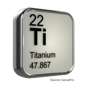
Which alloy was originally developed for aerospace applications but became one of the most common biomedical alloys? A) Inconel 718 B) Inconel 625 C) Ti-6Al-4V D) Hastelloy C22
What was the first rapid prototyping method to produce metal parts in a single process (and is one of the most widely used AM technologies to manufacture Ti-6Al-4V parts)? A) Powder-bed fusion (PBF) B) Directed energy deposition (DED) C) Sheet lamination (SL) D) Direct metal laser sintering (DMLS)
In what way does high temperature processing — specifically HIP below the annealing temperature (1470°F/799°C) — improve DMLS Ti-6Al-4V parts? A) Preserves surface roughness and enhances osteointegration B) Reduces porosity and enhances corrosion resistance C) Both A and B D) Neither A nor B
What is the ideal way to process 3D printed parts made using liquid binder polymers? A) Print the parts in-house followed by debind and sinter. B) Have AM parts delivered in-house for heat treating when parts are at the “Green” stage C) Have AM parts delivered in-house for heat treating when parts are at the “Brown” stage D) None of the above
Industry experts agree: 2025 is a year of significant, high-tech developments. In this Technical Tuesday, hear from three heat treat industry consultants on current and incoming technological advances, from miniaturization and customization to artificial intelligence.
Michael Mouilleseaux, general manager at Erie Steel, Ltd, opens the discussion by asking what role AI has in a perfect world of heat treating; Thomas Wingens, president of Wingens Consultants, predicts six major technologies to look for in 2025; and Dan Herring, a.k.a. The Heat Treat Doctor® and owner of The HERRING GROUP, Inc., points out how the trend toward smaller is affecting the heat treat industry.
This informative piece was first released inHeat Treat Today’sJanuary 2025 Technologies To Watch in Heat Treating print edition.
AI’s Place in Heat Treating?
by Michael Mouilleseaux
The benefits of AI are purported to be the ability to reduce the time required to complete complex tasks, such as data analysis, while reducing human error and providing both unbiased decision making and data-driven system enhancements … and by the way, it can operate 24/7 without breaks!
Does AI have a place in heat treating?
Here’s what I would want my heat treat AI (HT AI) to be able to do with a gas-fired atmosphere furnace.
Combustion System:
My HT AI will continuously monitor the free oxygen of all the burners and keep them at a perfect ratio, thereby optimizing performance and gas consumption. It will track these changes and provide analysis of any trends that it “perceives,” so to speak.
My HT AI will continuously monitor combustion air pressure and message me in time to have the air filters changed before it affects performance. It will track this and provide historical and prescriptive information.
My HT AI will periodically perform a “tube check,” whereby it will shut off combustion in a tube and monitor the free oxygen, recognizing that any diminishment from “atmospheric” O2 levels indicate the potential of a tube leak. It will track this and provide analysis of any trends that it perceives.
My HT AI will track when system thermal stasis is achieved, monitor gas consumption for each discrete heat treat cycle, provide analysis of trends that it perceives, and recommend thermal cycle changes to optimize these cycles.
My HT AI will facilitate the optimization of the critical human assets in process engineering, product quality and equipment maintenance.”
Michael Mouilleseaux
Atmosphere Control System:
My HT AI will continuously monitor the atmosphere flows required to achieve the requirements for each heat treat cycle. It will track “atmosphere recovery” and provide analysis of any trends that it perceives (i.e., increased usage as a precursor to a furnace leak).
My HT AI will periodically perform a furnace check, whereby it compares the composition of the Endo gas in the furnace to that exiting the generator, providing a measure of furnace integrity. It will track this and provide analysis of any trends that it perceives.
My HT AI will confirm “tube check” data (see above) with atmosphere usage to evaluate its potential effects on process integrity and make actionable recommendations. It will track these incidents and provide analysis of any trends that it perceives.
My HT AI will provide assurance of system performance and actionable information.
Shoot for the Moon:
My HT AI will have the unique ability to integrate metallurgical results with process information and thereby provide the ability to optimize the heat treating process AND metallurgical results.
My HT AI will allow me to input material chemical and hardenability data and, by comparing actual results with the calculated, or prospective results, provide confirmation of the thermal and quenching segments of the process.
My HT AI will be able to correlate IGO results with furnace integrity checks (i.e., leaks) and over time establish hard limits for allowable leak rates.
My HT AI will be able to correlate actual retained austenite levels in carburized case with furnace carbon potential and make data-driven process modifications to optimize this.
My HT AI will be able to correlate the shape of the case depth curve with the carburizing cycle and the material type, and it will make data-driven process modifications to optimize this.
My HT AI will have the ability to develop new heat treat thermal cycles specific to my furnaces extrapolated from existing data.
My HT AI will provide a level of system performance heretofore not achieved, that not only assures adherence to established standards but provides a clear path of continuous improvement via data analysis and actionable actions. Product results will be validated by total process control, and total process control will assure attainment of product results.
My HT AI will facilitate the optimization of the critical human assets in process engineering, product quality and equipment maintenance.
In short, my HT AI will afford the heat treating community the ability to finally jettison the mantle of “black art” and join the community of high-tech engineered processes.
About the Author:
Michael Mouilleseaux General Manager Erie Steel, Ltd
Michael Mouilleseaux has been at Erie Steel in Toledo, OH, since 2006 with previous metallurgical experience at New Process Gear in Syracuse, NY, and as the director of Technology in Marketing at FPM Heat Treating LLC in Elk Grove, IL. Having graduated from the University of Michigan with a degree in Metallurgical Engineering, Michael has proved his expertise in the field of heat treat, co-presenting at the 2019 Heat Treat show and currently serving on the Board of Trustees at the Metal Treating Institute.
2025 will be the year of invention and application. There are six major technologies to be looking out for: AI management software, giga casting for the EV industry, high-pressure quench furnaces, thermal processing specialty materials, processing for steel enrichment, and practices for cleaning consistency.
AI Management Software
Some new heat treat shop management software is now available. It utilizes artificial intelligence to save labor while documenting all processes in real time. The software easily adapts to the way we work and is much easier to learn and implement than the software of the past. I see this as the number one investment item for commercial heat treaters in 2025, as it is the cheapest and easiest way to automate with a great ROI while increasing quality and customer service.
Giga Casting
With Tesla as the main driver, very large so-called “GIGA” H13 aluminum dies of 3 to 8-ton weight have really taken off in the last years, in particular for new electric car models, and the demand for very high pressure quench furnaces is increasing in the U.S. (more to come in a later article).
Vacuum Oil Quenching
However, even with the most advanced designs and high-pressure efforts, gas quenching with nitrogen has its limits, and the use of helium is not considered anymore because of its immense cost, even with a recycling system in place. Vacuum oil quenching has become a viable alternative in recent years not only in combination with LPC (low-pressure carburizing) but also with the use of materials like AISI 52100 that would be typically heat treated in atmosphere integral quench furnaces but show lesser distortion with the variation of pressures over the oil bath, which can shift the oil boiling phase peak to lower temperatures (e.g., from 650°C (1200°F) at atmospheric pressure to 400°C (750°F) at 1 mbar pressure). Some new modern vacuum oil quench furnace designs have recently entered the market, showing excellent surface cleanliness and distortion results. Aside from the better quality, they offer a much safer, cleaner and more pleasant work environment.
Specialty Materials
In general, we see a higher demand for the thermal processing of specialty materials; for example this is seen with the hydrogen decrepitation of titanium, tantalum, niobium, or rare earth element materials, powder processing or sinter processes, and surface diffusion processes.
Steel Enrichment
Enriching stainless steel with nitrogen is not new, but it is gaining momentum and more applications. One method for\ low-temperature processes on austenitic stainless steels around 370°C (690°F) is called S-phase case hardening, and the high temperature version around 1100°C (2010°F) is called solution nitriding. Both processes were initially established in the early 90s in Europe but seem to be gaining momentum and more comprehensive applications worldwide over the last years.
Figure 1. For 2025, “We see more fully enclosed vacuum solvent cleaning in heat treat shops to ensure a higher standard and consistency of the surface cleaning results compared to the fading of water cleaners.” – Thomas Wingens, WINGENS CONSULTANTS
Cleaning Consistency
Speaking of surface processes: The cleaning of components has been a thankless process, especially in commercial heat treatment, as it is seen as a necessity that is not necessarily paid for by the clients but is necessary to have uniform dissociation on the surface of a part to ensure a uniform case (e.g., nitriding case). There are well-defined standards for temperature uniformity and hardness testing, but cleaning consistency needs to be addressed, as it can be very impactful. We see more fully enclosed vacuum solvent cleaning in heat treat shops to ensure a higher standard and consistency of the surface cleaning results compared to the fading of water cleaners.
About the Author:
Thomas Wingens President WINGENS CONSULTANTS
Thomas Wingens has been an independent consultant to the heat treat industry for nearly 15 years and has been involved in the heat treat industry for over 35 years. Throughout his career, he has held various positions, including business developer, management, and executive roles for companies in Europe and the United States, including Bodycote, Ipsen, SECO/WARWICK, Tenova, and IHI-Group.
Everywhere we turn today, the products we use are getting smaller, more compact and more powerful. This is true across all industries, from aerospace to automotive, from medical to electronics, and from energy to semiconductors to name a few. Today, miniaturization, portability and customization have become major design objectives for almost all manufacturing segments.
These trends are irreversible and are, or will be, found even in the most unlikely of places — both in mining of resources taking place deep under the ocean floor and eventually on other planets. The key question then becomes, how will all of this influence our heat treating operations?
Miniaturization, Portability and Customization Today
Given the ever-increasing demand for higher performance in a smaller footprint, we have often focused our energies on taking existing products and adapting them for use. But in the long term, this is not sustainable. For example, not only is gear noise reduction critical in our submarines, but the medical and robotics markets are continuously searching for smaller, more efficient, more application specific and more intelligent drive systems and motors with increased torque density.
Heat treatment will experience a metamorphosis and emerge more broadly as thermal treatment. The age of metals as we have known it has become the age of materials: ceramics, composites, powder materials, glasses, polymers, fiber-reinforced plastics, and even nanomaterials.
Dan Herring, The Heat Treat Doctor®
Another example, although not new, is miniaturization in vehicle electronics, especially as it relates to data collection where demand is high for smaller, more powerful and, yes, cheaper components. Integration into the electronic control units via on-board power systems has seen the need for more cables in vehicles and positioning connectors, which means more contacts/connections on the electronic components without significantly increasing the installation space.
Similarly, there is a huge demand for portability. This is true not only in our electronics (just think about how cell phones or computers have changed over the last ten years), but there is a growing need for portable medical devices so that medical care can be brought to the patient rather than the other way around. For example, longer battery life and lighter weight are critical for devices such as portable oxygen concentrators.
What Does This Mean for the Heat Treatment Industry?
Looking ahead, we will see both short and long-term changes to our industry. Happening today and continuing in the near term, heat treaters are working closer than ever with design and manufacturing engineers as they focus on products that reduce environmental impact, are produced at lower unit cost, and with improved part quality. Still, the era of mass recalls must come to an end. And the cost of heat treating is less than it was even a decade ago. But as manufacturing demand evolves due to consumer expectation, process and equipment flexibility will become keys to meeting the highest quality standards in an on-demand world.
Historically, changes in the heat treat industry has been evolutionary and incremental in both nature and effect. There have been notable exceptions such as the invention of the oxygen probe or low pressure vacuum carburizing. But to meet the manufacturing demands of the future, change will need to be more revolutionary and abrupt in nature, a game changer.
Given the ever-increasing demand for higher performance in a smaller footprint, we have often focused our energies on taking existing products and adapting them for use. But in the long term, this is not sustainable. For example, not only is gear noise reduction critical in our submarines, but the medical and robotics markets are continuously searching for smaller, more efficient, more application specific and more-intelligent drive systems and motors with increased torque density.
Dan Herring, The HERRING GROUP, Inc.
Heat treatment will experience a metamorphosis and emerge more broadly as thermal treatment. The age of metals as we have known it has become the age of materials: ceramics, composites, powder materials, glasses, polymers, fiber-reinforced plastics, and even nanomaterials. As a result, we will find ourselves needing, for example, to expand our heat treat capability and equipment to deal with such items as process temperature ranges from -200°C to 1850°C (-330°F to 3360°F) or greater or at pressure/vacuum levels heretofore only achievable in laboratories or specialty applications.
As product sizes decrease, load sizes will become smaller out of necessity. And as a result, our heat treat equipment must be small lot capable with tighter controls to achieve higher quality along with tremendous process flexibility.
Final Thoughts
History’s enduring legacy is that change is inevitable. Just think back to how the heat treatment industry has evolved, from the campfire to the blacksmith to the modern heat treater, from the artisan to the era of mass production, from the art of heat treating to the science of heat treatment. The lesson is that to adapt, one must constantly innovate and invent. Miniaturization, portability and customization in whatever form they take are here to stay. Perhaps even teleportation (the ultimate miniaturization?) isn’t that far off after all, considering flight was unheard of a little over a century ago.
About the Author:
Dan Herring (The Heat Treat Doctor®) The HERRING GROUP, Inc.
Dan Herring has been in the industry for over 50 years and has gained vast experience in fields that include materials science, engineering, metallurgy, new product research, and many other areas. He is the author of six books and over 700 technical articles.
As Thomas Bauernhansl, professor of Production Technology & Factory Operations at the University of Stuttgart, aptly states, “We are going from more supply-oriented production to a demand-oriented one. In many cases, the customer determines which version he wants to have [of] a product — the manufacturer adapts to this and his processes accordingly.”
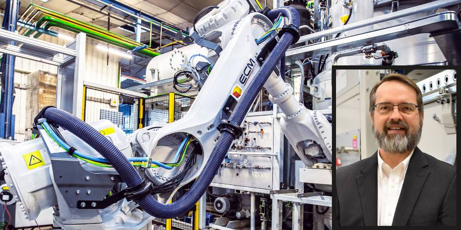
This shift is critical for the heat treat industry, where the need for advanced automation and robotics integration is paramount to achieve higher efficiency, consistent quality, and reduced costs.In this Technical Tuesday, Dennis Beauchesne, general manager at ECM USA, discusses the increase in use and installation of automation and robotics in manufacturing and specifically how companies within the heat treat industry have adapted to their implementation—and become innovators in their usage.
This informative piece was first released inHeat Treat Today’sJanuary 2025 Technologies To Watch in Heat Treating print edition.
Industry Automation
In the last 10–15 years, an upward trend is consistent with the increased investment value of integrated automation within a heat treatment plant. At the beginning of the 2000s, it was common to have an automatic transport car transporting batches to different stations, but, in the last five years, far more complex automation solutions are in demand. In order to meet the requirements of future industry robotics and automation, our industry must adapt to the new and improved technology offerings and standards that are being used in other industries.
Figure 1. Annual robotics installation by industry 2021-2023
According to World Robotics, there has been a significant increase in robotics usage and installations since 2020 (Figure 1). For example, the automotive industry shows installations almost doubled from 2020 to 2022 with 83,000 installations in 2020, compared to 136,000 installations in 2022. The industrial robot market was expected to grow by 7% in 2023 to more than 590,000 units worldwide. Although it exceeded 500,000 installations, robotics were down 2% (possibly due to COVID-19) compared to the prior record year. Of interest to note for the automotive industry, the industry increased its robotics demand in 2023 to surpass electronics with a 25% share (electronics was close with 23%, down by 5% due to inventory levels stabilizing after supply chain bottlenecks mostly vanished).
Table 1. North America’s robotics comparison 2022 to 2023 Source: World Robotics
Specifically for the United States and Mexico, peak robotics installation demand was documented in 2022, but demand has been consistent within +/-5% (Table 1). The future of robot installations is trending to grow and exceed 50,000 units in North America for 2024. Nearshoring of supply chains will create demand for automation technology in the years to come, according to Christopher Müller in his World Robotics 2024 – Industrial Robots presentation.
Manufacturing Concepts
The company SEW has previously published its ideas and concepts of autonomous transporters distributing the raw parts to the production cells, after the soft processing to the hardening plant, and finally the hard machining (Figure 2). All steps are configured within the component so the process steps can be well documented on a component basis.
Figure 2. SEW concept from Hiller, “The networked hardening shop,” 2019 Source: ECM GmbH
As can be seen in the SEW Figures, the original hardening plant is shown as a continuous furnace. However, this type of plant technology can be seen as contradictory to current production needs. To be compliant with this new philosophy, plant technology must be as modular, flexible, and automatable as the rest of the production layout and components. Heat treatment must also be controllable and unloadable with automatic transport units. Robots must be able to load batches and navigate the plant (according to CHD, steel, part numbers, etc.). The smaller the batch size, the larger the value of robotic component documentation. Furthermore, a reduction in batch size is advantageous for flexibility, costs, and heat treatment of many requirements for production runs.
Heat Treatment & Robotics
A heat treatment plant can implement recommendations for the future of industry automation by acquiring technology for:
Automatic loading/unloading
Component recognition systems
Automatically loaded/read recipe systems
Smaller batch sizes with a wide variety of variants
Heat treatment of different applications or steels in small quantities
Maintenance/repair detection
Benefits of automating part or all production line steps include:
Shorter process times
High CHD (Case Hardening Depth) uniformity and lower distortion
Lower operating costs and labor reduction
These technologies have existed and are being implemented in heat treat operations for a few years now. The results are clear and the benefits are proven through higher quality parts, highly efficient heat treat operations, and overall more efficient production facilities.
As many machining operations have been robotized, this allows the downstream heat treat operations to easily take advantage of part placement in dunnage and plant transport systems, whether manual or automated.
Figure 3. ECM Vision System Source: ECM Robotics
Batch Loading with Robotics
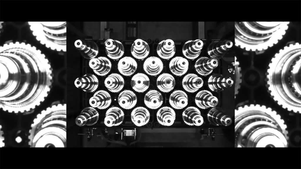
Bulk goods-loading (such as clips, links, and other small parts via weight detection) as well as loading and unloading of truck shafts in fixtures and in straightening machines are just a few examples of production areas that can benefit from robotics/automation. Visual recognition systems can identify gears/parts based on the diameter or by the number of teeth on the gear and can then sort them by these features (Figure 3).
Like the visual locating of the parts by cameras, they can also be used for tracking parts and loads within a heat treatment cell. A good amount of work has been done in this area for heat treating. This work covers part marking, tray/fixture encoding, and part weighing scenarios, and allows the heat treat system to accurately process all the different parts coming through the heat treat system with the correct process recipe.
Some of the work being done has been implemented with a QR code marking system for each part before heat treatment. To ensure the correct recipe or heat treatment is performed on the proper part, this scanned code works with the heat treatment system controls to upload the correct recipe to the proper cell. This information can be further analyzed to indicate precise placement in the heat treat tray through virtual tracking.
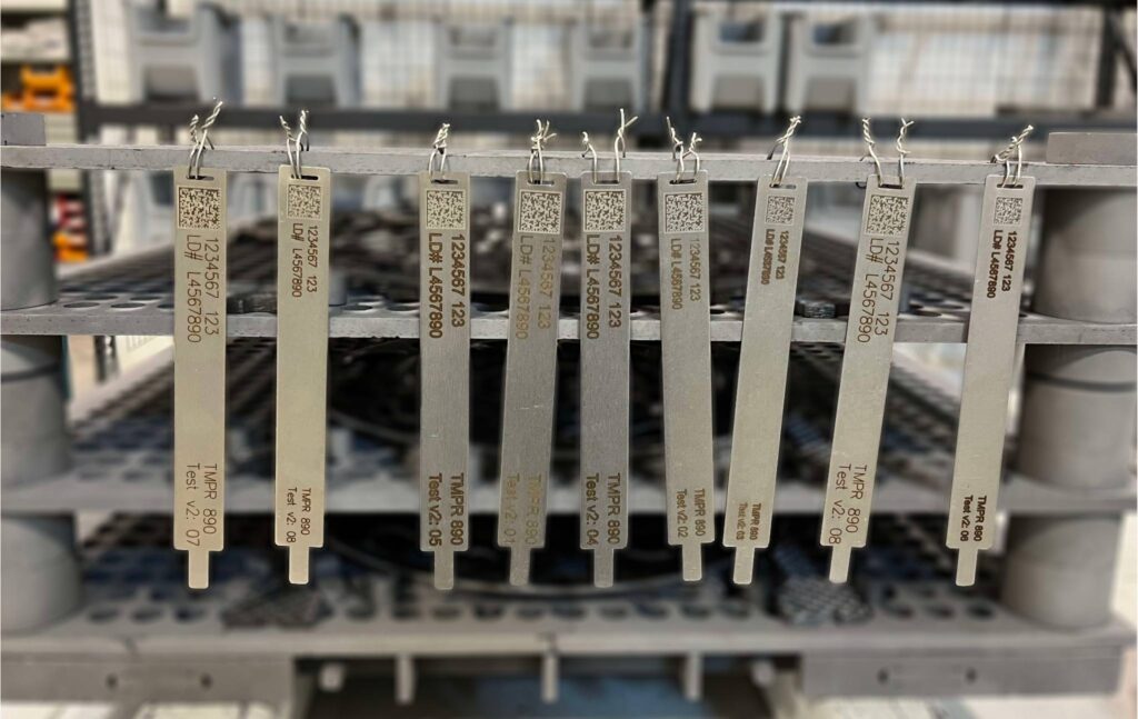
Figure 4. QR code heat treat test picture Source: ECM USA Synergy Center
In Figure 4, you can see in the details that this client has reviewed and tested to assure the code is visible before and after heat treating with a carburizing and hardening process.
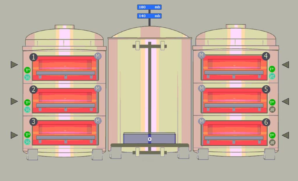
These parts are tracked when entering the system and also noted as to which heat treat tray they are on by using a binary code with holes in a tray or on a strategically placed bar code plate on the tray. With this system, they can be scanned by a camera before entry and upon exit of the furnace (Figure 5). This tray scanning can also indicate how many cycles the trays have on them to ensure the trays stay in good condition and can be cycled efficiently.
Let’s look at the SEW production concept again and re-imagine it with a more efficient vacuum furnace technology with robotic integration. In this concept, the vacuum furnace system forms the “spatially distributed production reserve” which helps autonomous transport units as “situationally self-controlling” material is delivered.
The QR code on the component represents the “knowledge-based” running card. The robots recognize the components by means of the QR code and are loaded onto the appropriate heat treat trays. The heat treatment can then be carried out on a component-related, flexible, and documented basis. Traceability of production can also be ensured (Figure 6).
Loading of the parts can be done efficiently through a series of dunnage that hold the part in specific locations which assist the robot to locate, lift, and place the parts in the heat treat tray. This method doesn’t always need to be a perfect location for the incoming work as we now have 2D and 3D cameras that can work in tandem to locate parts, even in odd stacking or randomly loaded bins.
In a recent installation, a heat treater automated their gear cutting operation to prepare the dunnage before heat treat. Therefore, the heat treat robotics phase was simplified by storing each part in a specification location for the robot to “see” with its vision system. These parts are then scanned and automatically connected to the part’s recipe as stored in the system. In a modular system using low pressure carburizing, individual cells are utilized, and production is recipe driven. These recipes are pre-developed and stored to allow each cell to utilize the recipes for many different parts. In this case, after a part is scanned, the recipe is uploaded into the next available cell and the scanned parts and heat treat fixture is moved to the cell (Figure 7).
Figure 7. Modular vacuum furnace for low pressure carburizing Source: ECM USA
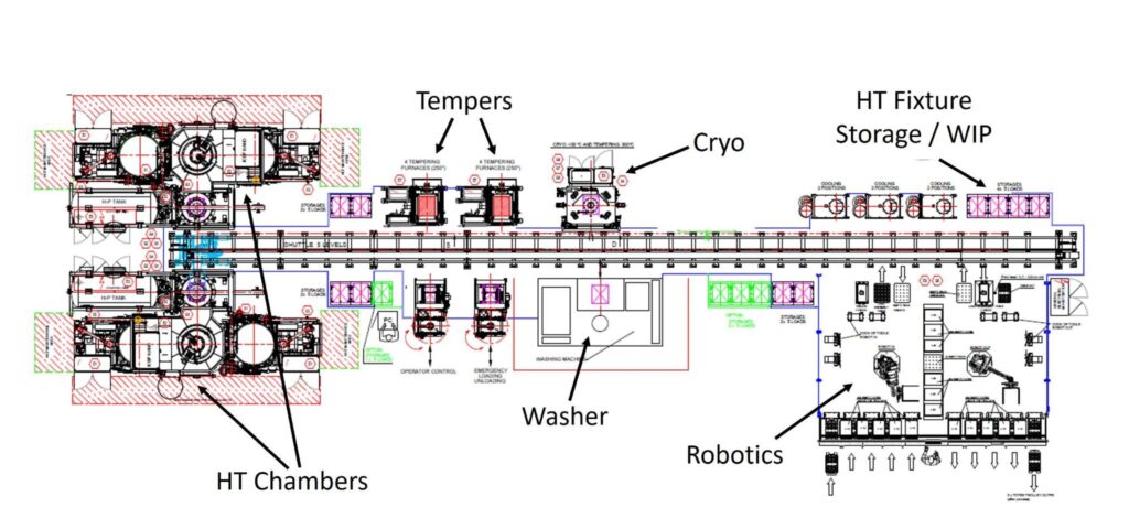
Figure 8 was designed to use over 175 different parts with nine different heat treat processes which included carburizing and slow cooling, hardening, tempering, cooling after tempering and cryogenic treatment.
With further considerations for additional benefits of the automated system, fixtures were optimized by using CFC (carbon fiber composite) base trays. These trays are not only extremely stable and have non-existent growth/warpage, but they also help with robotic placement before and after heat treatment. CFC trays are flat, or can be machined to conform to part geometry, which helps to reduce or minimize distortion related to fixture warpage or creep.
Figure 8. LPC and robotics configuration Source: ECM USA
Many system designs have been proposed to a variety of clients; however, the end goal is to design a system that is “standard.” This standard design needs to incorporate different forms of dunnage, bins, boxes, and pallets to allow a commercial heat treater to easily program the system whenever the next part comes in from their client, whatever it may be. This is a challenging task and needs to be broken out by weight category to design the robot’s reach and end tool design. In this case a robot cell offline of the heat treat furnace can be built and utilize, and ultimately use, an AMR (automated mobile robot) or AGV (automated guided vehicle) to bring the built loads to the furnaces (Figure 9).
Vacuum furnace systems have a clear advantage over traditional atmospheric systems with many features which lend themselves to integrate into the machining area with robotics and automation.
The fact that an LPC (low pressure vacuum) furnace system can process loads via a recipe input and each cell can be used to process a different case depth, or hardening cycle is highly advantageous when processing a wide variety of parts. In addition, the LPC process provides a more uniform case depth throughout the part to make a stronger part along with high quality processing. The vacuum furnace cells can be arranged in many ways to fit into existing facilities and to be able to use many methods of automation especially including robotics.
Quenching is also a key element in any hardening heat treat process. LPC furnace systems are usually associated with high pressure gas quenching (HPGQ) in a separate chamber to provide the best quenching performance. This gas quenching technique provides a clean process for each part and allows the use of CFC fixtures. There is also no requirement for post cleaning as is necessary with oil quenching.
Providing quality low pressure carburizing, clean and precise gas quenching, CFC trays for better uniformity and keeping the parts flat, and the automation benefits of robotics makes for a state-of-the-art heat treating production operation and thus completes the heat treat paradigm shift.
Figure 10. Robot loading Source: ECM USA
Conclusion
The heat treat industry wants and needs automation and robotics integration to advance production, reduce costs, and improve the overall quality of production. With traditional technology, process data evaluation and self-configured recipe values are not possible. Therefore, component analysis should be automated to meet and achieve consistent and reliable recipe values (mass flow, time). With the increase in robotics demand, vacuum furnace technology meets the variable requirements of “demand-oriented” production. Due to the flexibility of this technology, small batch size systems can be automated with robots or as bulk material.
References
Hiller, Gerald. “The networked hardening shop – the challenge to the hardening plant in the world of Industry 4.0.” ECM GmbH. Paper presentation, 2019.
Dennis Beauchesne brings experience of over 200 vacuum carburizing cells installed on high pressure gas quenching and oil quenching installations. He has worked in the thermal transfer equipment supply industry for over 30 years, 23 of which have been with ECM USA.
The thermal processing industry is a good example of how the on-site production of hydrogen by water electrolysis can be beneficial for many of its processes and for reducing the CO2 of its plants. In today’s Technical Tuesday, David Wolff, industrial sales director at Nel Hydrogen, discusses how, from plasma spray to metal AM binder jet to annealing at rolling mills, industries across medical, automotive, and beyond are looking to water electrolysis for hydrogen production.
This informative piece was first released inHeat Treat Today’sDecember 2024 Medical & Energy Heat Treat print edition.
Hydrogen atmospheres are widely used in high temperature thermal processing, including annealing, brazing, PM, MIM, and binder jet AM sintering, metal-to-glass sealing, and related processes such as thermal spray. Hydrogen helps heat treaters achieve acceptable product characteristics. It’s used as a very powerful reducing agent, and it actively cleans surfaces as compared to inert gas atmospheres which only displace oxygen.
Relative to hydrogen’s use in helping plants decarbonize, it’s a fact that major OEMs buying heat treating services and heat treated products are demanding that their suppliers report their decarbonization progress. To meet the needs, hydrogen generation is becoming ever more compelling to heat treaters to ensure hydrogen for atmosphere needs inside the plant, and to help minimize their carbon footprint.
The Clean Energy Supply Conundrum
Most U.S. heat treating facilities get their atmosphere components delivered by truck. The truck emits CO2 and the hydrogen on that truck is likely “gray” hydrogen made from natural gas. Hence, the carbon footprint from their hydrogen use is notable. Importantly, the electricity grid operators are actively seeking ways to enhance the business success of providers of low carbon electricity. The key issue with those providers — solar, wind, hydro, and nuclear — is that they cannot easily follow the ups and downs of demand. Instead, consumers get electricity from those resources when the wind is blowing, the sun is shining, or the river is high. In the case of nuclear plants, they preferentially run at near fixed output, day and night. They run continuously regardless of demand. As the grid demand is very low at night, they get very low prices for the electricity they generate. They only make money for 12 or so hours a day. That’s why a lot of nuclear plants are threatening shutting down for economic reasons.
Taking Advantage of Low Demand Period Energy Prices for Use During High Demand Hours
Consider this scenario: What if a client with electrolysis capacity to produce hydrogen, such as a heat treater, could buy electricity at lower nighttime prices to make the hydrogen it needs during the day shift for its various processes, perhaps even heating their furnaces? The clean energy provider would be pleased to have more income during its low demand, low price times. The heat treat plant is happy saving money buying decarbonized electricity at low demand prices to make clean hydrogen for its various thermal processes and to operate its furnaces. And, the heat treat company’s OEM clients demanding decarbonization are satisfied, too.
How To Get Started
The scenario described above is a practical and real one for the heat treat industry today. Nel Hydrogen recommends that a heat treat company begin with a plan. That plan may comprise several phases. It’s important to seek out a knowledgeable hydrogen partner in this endeavor to specify exactly what’s needed. For heat treat applications, users generally would want compact equipment, extreme hydrogen purity, load following, near-instant on and instant off, and sufficient hydrogen pressure that make it flexibly suited for a variety of thermal processes, and for hydrogen storage addition at a later time if desired.
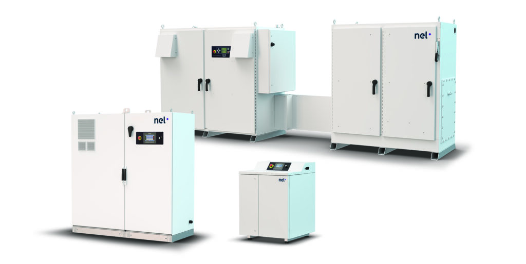
Figure 1. Compact hydrogen generators using water electrolysis for thermal processing applications (Source: Nel Hydrogen)
Both batch and continuous processes can be served. Batch processes may benefit from a small amount of surge storage at the outset. By combining on-site hydrogen generation with a small amount of in process hydrogen surge storage if needed, on-site hydrogen generation can be used to meet the needs of batch processes such as batch furnaces and thermal spray. By carefully choosing generation rate and pressure, and surge storage vessel volume and pressure capacity, the combination of generation with surge storage can provide maximum process flexibility while minimizing the amount of hydrogen actually stored.
The presence of a small amount of hydrogen surge storage also protects clients’ parts in case of an electric interruption that stops hydrogen production. The surge storage hydrogen can protect the parts while they cool under a reducing atmosphere.
In practice, specific client priorities such as minimum hydrogen storage, or lowest system capital cost, or highest degree of expandability, or least amount of space occupied, can be met by choosing the specific hydrogen generator capacity and surge storage system employed for any particular production challenge.
Examples of Thermal Processors Producing Hydrogen On Site with Water Electrolysis
Decarbonization will be a near-future requirement as part of the global effort to evolve towards a cleaner, greener world. On-site hydrogen generation in industry makes great sense to align with those initiatives. Right now, the thermal processing industry is experiencing the benefits of producing hydrogen on site for its production processes, and the decarbonization demand will be easier to accommodate with that infrastructure in place.
Here are a few examples of companies performing a variety of thermal processes that have made the decision to use water electrolysis to produce hydrogen on site:
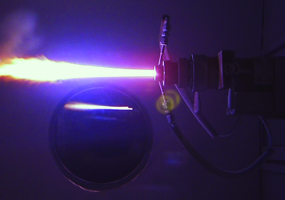
Plasma Spray of Cast Iron Cylinder Liners
One of the most compelling examples has been implemented by two different U.S. automakers to accommodate the increasing use of low-weight aluminum engine blocks in today’s high efficiency vehicles. Aluminum blocks must have a cast iron lining on the inside of the cylinder bore to maximize the durability of the engine. (Older readers may recall the notorious Chevy Vega that used an aluminum engine without a cast iron liner. The author’s wife had one Vega which burned through three engines!)
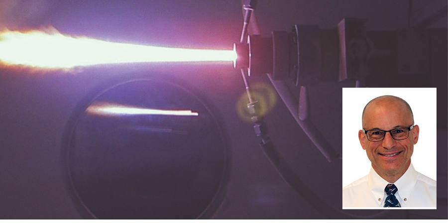
Figure 2. Plasma torch used to spray-apply metal coatings in additive
manufacturing processes (Source: Shutterstock)
The traditional approach to provide a cast iron liner was to drive a sleeve into the aluminum engine block. However, a new technology has been commercialized by which the cast iron liner is spray-applied using a plasma torch. The torch uses hydrogen and argon gases to add energy and maintain the necessary low oxygen atmosphere. The plasma spray was a new addition to engine production facilities that had not previously been equipped with hydrogen supply and thus elected to generate their own to minimize delivered hydrogen and avoid the need for hydrogen inventory and extensive supply piping.
The electrolyzers recommended for plasma spray applications are compact and produce high purity hydrogen of better than UHP grade at 200+ psig pressure, with less hydrogen stored than would fill a party balloon bouquet. About the size of a washing machine or refrigerator, depending on the model, each unit is low maintenance, compact, quiet, and can be installed nearly anywhere in a facility.
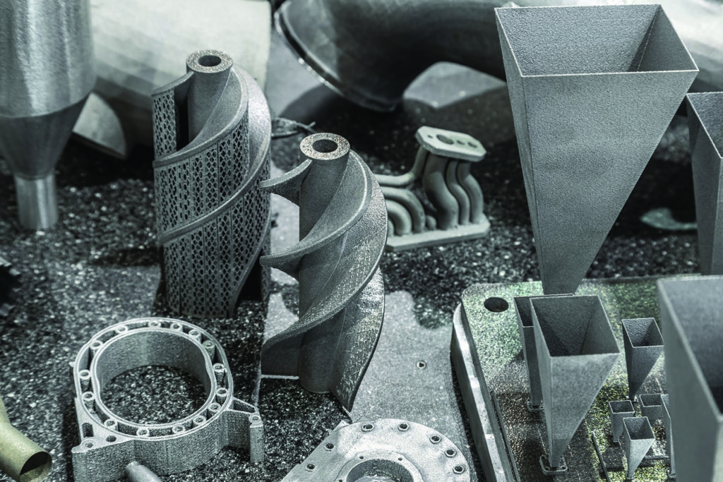
Metal Additive Manufacturing (AM) Binder Jet
One of the most exciting approaches to metal AM is the technology called binder jet, which creates a near net shape part using polymer and wax binders to adhere metal powders. After the part is formed, the binders are chemically or thermally removed. Then the part is sintered to attain near net shape and full part density. Hydrogen is required for the sintering atmosphere to prevent oxidation of the part during the sintering process. Binder jet technology promises to provide for mass production of individually customized parts at high production rates and consequently lower costs than parts produced individually.
Figure 3. Binder jet metal AM parts sintered in a hydrogen atmosphere (Source: Shuttershock)
Many new metal AM production facilities are being established in factories that are not already equipped for the delivery, storage, and internal piping/distribution of hydrogen. As such, many have chosen instead to use zero inventory hydrogen made on site to minimize infrastructure investments. Electrolyzers for small-scale applications requiring up to 230 scf/hr of hydrogen gas at 99.999+ % purity are advised for metal AM. About the size of a large refrigerator, the units require minimal facility floor space, are easy to maintain, and can be installed in any non-classified space. Applications for AM include medical, electronics, industrial, and automotive components.
Annealing at Rolling Mills
Plate and strip metal are processed in rolling mills where the thickness of the metal is reduced by alternating “cold” rolling steps followed by intermediary hot annealing steps. Cold rolling makes the metal more brittle, so it is necessary to have an annealing step following each rolling step. The metal is alternately thinned and then softened for what could be several iterations. Hydrogen is required for the annealing steps to maintain metal surface quality while heated. Because of the periodic market disruptions in delivered hydrogen from plant outages or trucking interruptions, several rolling mills have chosen to generate hydrogen on site to augment or entirely replace their delivered hydrogen supply. The benefits that the plants experience are primarily focused on supply reliability. Of course, they are also eliminating the carbon footprint associated with truck delivery. In this case, the carbon footprint of the generated hydrogen is determined by the particular electricity generating mix that serves the plant site.
Most often at rolling mills, electrolyzers that produce up to 1,140 scf of hydrogen gas at 99.999+ % purity are best suited for the hydrogen requirement. These units replace the need for hydrogen tube trailers or liquid hydrogen storage. They can be installed in the mill or can be containerized outdoors, offering flexible siting and reduced operational safety risks compared to delivered hydrogen.
Figure 4. Steel rolls are heated in an annealing step to soften the metal during production. (Source: Istock)
On Track Towards Decarbonization
Described in the examples above, once the means to generate hydrogen is chosen at a thermal processing facility, the company can move further along the decarbonization journey. This may be to apply a strategy as outlined in the electricity scenario whereby the company takes advantage of low demand rates or institutes an alternative creative idea. Certainly, as more and more clients demand proof that suppliers are reducing their carbon footprint, more strategies will be developed and implemented to serve the thermal processing industry. Simply generating hydrogen on site removes the trucking emissions factor and is a beneficial and practical starting point.
About the Author:
David Wolff Eastern Regional Sales Manager Nel Hydrogen
David Wolff has 45 years of project engineering, industrial gas generation and application engineering, marketing and sales experience. He has been at Nel Hydrogen for over 25 years as a sales and marketing leader for hydrogen generation technologies.
For more information: Nel Hydrogen at sales@nelhydrogen.com.
The Heat Treat Doctor® has returned to offer sage advice to Heat Treat Today readers and to answer your questions about heat treating, brazing, sintering, and other types of thermal treatments as well as questions on metallurgy, equipment, and process-related issues.
Contact us with your Reader Feedback!
Clients often want to know or specify that their component part surfaces are “bright” or “shiny” or “clean.” Other times they desire to have a surface condition that is “scale free” or “oxide free” after heat treatment. But how, if at all, can we quantify what these terms mean? Let’s learn more.
“Shiny” and “bright” are words that are highly subjective. This is often a source of confusion not only for the heat treater, but the manufacturer and, in some cases, even the end user of the products. Heretofore, the answer depended on one human being’s interpretation as opposed to another, and evaluations depend not only on the type of material but also the mill practices used, manufacturing methods employed, heat treatment processes, and the level and type of contamination introduced before and after processing.
Traditional Approach
Figure 1. Temper color chart atmosphere or tempering in air or an “inert” gas such as nitrogen. Source: Abbott Furnace Company
Traditionally, we have relied on color charts (Figure 1) to tell the approximate temperature at which discoloration took place, that is, an oxide formed on the (steel, stainless steel, or tool steel) surface of a component part. This method is still in use today when cooling parts in a furnace
As mentioned, the perception and interpretation of color is different for different people. Lighting (natural light or plant illumination), the environment in which one views color, eye fatigue, the age of the observer, and a host of other factors influences color perception. But even without such physical considerations, each of us interprets color based on personal perception. Each person also verbally describes an object’s color differently. As a result, objectively communicating a particular color to another person without using some type of standard is difficult.
There also must be a way to compare one color to the next with accuracy.
New Approach
Today, portable spectrophotometers (Figure 2) are available to measure color and help quantify brightness measurements. These types of devices are designed to meet various industry standards including:
In simplest terms, a spectrophotometer is a color measurement device used to capture and evaluate color. Every object has its own reflectance, or the amount of light it reflects, and transmittance, or the amount of light it absorbs. A reflectance spectrophotometer shines a beam of light and measures the amount of light reflected from different wavelengths of the visible spectrum, while a transmission spectrophotometer measures how much light passes through the sample. Spectrophotometers can measure and provide quantitative analysis for just about anything, including solids, liquids, plastics, paper, metal, fabric, and even painted samples to verify color and consistency.
Spectrophotometers provide the solution to the subjective problem of interpreting the color of the surface of a component part that has been heat treated, brazed, or sintered because they explicitly identify the colors being measured; that is, the instrument differentiates one color from another and assigns each a numeric value.
As an example, the brightness of steel tubes annealed in a rich Exothermic gas atmosphere was measured against tubes that had not been processed (Figure 3). Having this definite measurement of the surface changes allowed the heat treater to provide their client with a definitive statement on the change after processing.
CIE Color Systems
The Commission Internationale de l’Eclairage (CIE) is an organization responsible for international recommendations for photometry and colorimetry. The CIE standardized color order systems include specifying the light source (illumination), the observer, and the methodology used to derive values for describing color, regardless of industry or use case.
Though spectrophotometers are the most common, for some applications colorimeters can also be used, but these are in general less accurate and less suitable for a heat treat environment.
There are three primary types of spectrophotometers on the market today used for print, packaging, and industrial applications: traditional 0°/45° (or 45°/0°) spectrophotometers, primarily used for the print industry; sphere (or diffuse/8°) spectrophotometers, primarily used in the packaging industry; and multi-angle (MA) spectrophotometers, for use in industrial environments. These instruments capture color information, and in some cases can capture appearance data (e.g., gloss).
Multi-angle (MA) spectrophotometers are best suited for measurements involving special surface effects, such as those found on metal surfaces and coatings and include those with surface contaminants and even can quantify cosmetic appearance. These are typically used on the shop floor, in the lab and in quality control, and even can be found in shipping areas.
MA spectrophotometers require users to verify five or more sets of L*a*b values or delta these terms). They typically have an aperture size of 12 mm, which is too large for measuring the fine detail that occurs in many small-scale industrial applications. Primary illumination is provided at a 45° angle. Some models have secondary illumination at a 15° angle.
Figure 3. Example of a product test — color and oxidation level test. Source: X-RIte
An application example for an MA spec trophotometer lies in their use for collecting colorimetric data on special effects coatings in the automotive industry, capturing reliable color data in cases where special effect coatings are used.
Final Thoughts
In this writer’s opinion, a spectrophotometer should be in every heat treat shop! You will be doing both yourself and your customers a valuable service and take the guesswork out of one of the most commonly asked questions – is it bright?
References
Herring, Dan H. Atmosphere Heat Treatment Volume 1. BNP Media, 2014.
X-Rite Pantone. “A Guide to Understanding Color.” Accessed October 10, 2024. https://www.xrite.com/learning-color-education/whitepapers/a-guide-to-understanding-color.
X-Rite Panatone. “Tolerancing Part 3: Color Space vs. Color Tolerance.” Accessed October 10, 2024. https://www.xrite.com/blog/tolerancingpart-3.
X-Rite Pantone. “X-Rite Portable Multi Angle Spectrophotometers.” Accessed October 10, 2024. https://www.xrite.com/categories/portable-pectrophotometers/ma-family.
About the Author
Dan Herring “The Heat Treat Doctor” The HERRING GROUP, Inc.
Dan Herring has been in the industry for over 50 years and has gained vast experience in fields that include materials science, engineering, metallurgy, new product research, and many other areas. He is the author of six books and over 700 technical articles.
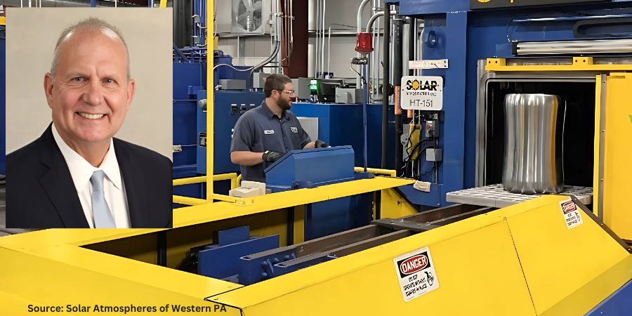
Despite years of research and development that resulted in several important technological innovations, the constraints of high-pressure gas quenching are ever more evident. In today’s Technical Tuesday, Robert Hill, FASM president of Solar Atmospheres of Western PA, addresses the creation of a new, robust style of vacuum oil quench furnace. The results challenge the schematics in how the next generation of oil quench furnaces should be designed, built, and operated.
This informative piece was first released inHeat Treat Today’sNovember 2024 Vacuum print edition.
Introduction
After decades of research and development that resulted in several important technological innovations, the constraints of high-pressure gas quenching are ever more evident. Gas cooling runs into efficacy issues when compared to liquid quenchant cooling, chiefly for heavier cross sections. This stays true even when using specialized inert gas blends and heightened gas pressures.
Additionally, it is undeniable that stringent liquid quench Aerospace Material Specifications (AMS) standards for certain aerospace alloy steels will never change. In fact, many industry standards (e.g., SAE/AMS and U.S. defense standards) and client specifications often mandate oil quenching of alloys or component parts.
To meet the demand for an effective, sustainable liquid quench solution, Solar Manufacturing with Solar Atmospheres engineers worked through the tumultuous period of the pandemic to create a new, robust style of vacuum oil quench furnace. Their work culminated in a vacuum oil quench furnace with a 36″ x 36″ x 48″ hot zone that operates up to 2000°F and can accommodate a weight capacity of 2000 lbs. With high uptime reliability and excellent metallurgical results, the NEO™ represents a paradigm shift in how the next generation of oil quench furnaces should be designed, built, and operated.
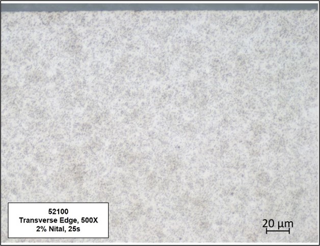
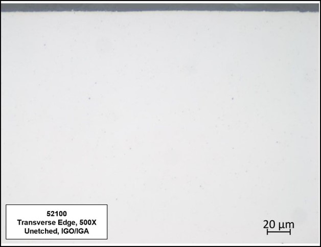
Figure 1. No decarburization, carburization, or surface contamination when tested in accordance with AMS2759/2 Source: Solar Atmospheres of Western PA
Rigorous Design for Metallurgical Excellence
The next generation of oil quench furnaces heralds an era of metallurgical excellence. This is made apparent across three key measures: control over surface contamination, prevention of parts cracking, and flexible processing of dissimilar materials.
No Surface Contamination
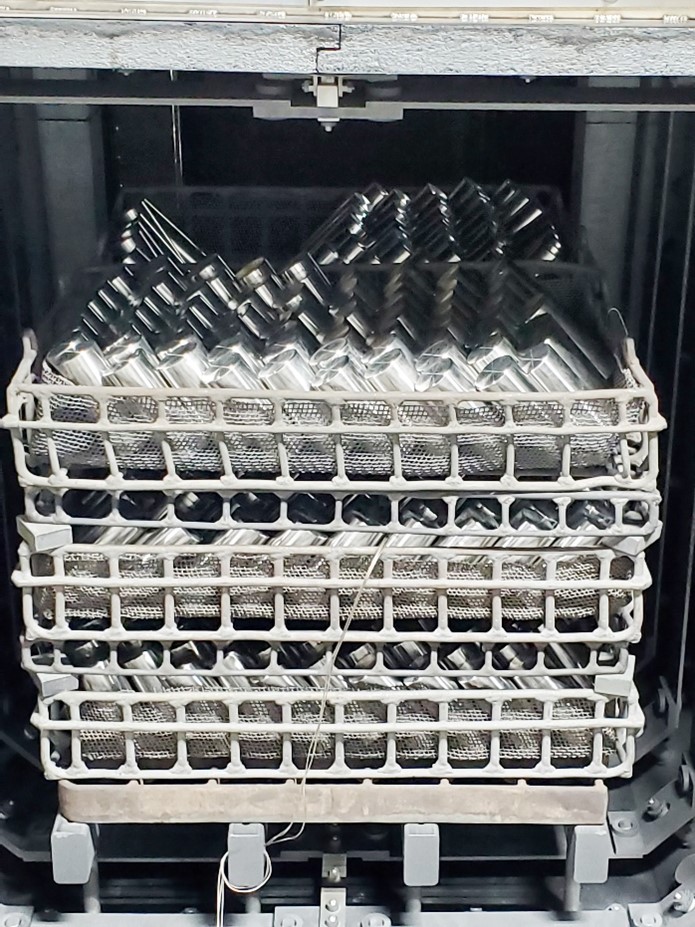
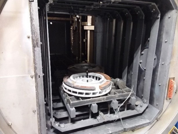
Figure 2. Loading in the NEO furnace Source: Solar Atmospheres of Western PA
By implementing a vacuum design to the oil quench furnace, the research team avoided issues faced by traditional atmosphere oil quench furnaces, such as surface contamination and intergranular oxidation/intergranular attack (IGO/IGA). Additionally, they meticulously addressed design concerns regarding oil backstreaming in the new multichambered vacuum system. After two years of usage, the hot zone has remained pristine and oil-free.
By effectively removing the possibility of any surface contamination, both IGO and decarburized or carburized surfaces on oil quenched components are eliminated. These critical metallurgical features are unattainable in traditional gas-fired Endothermic batch furnace equipment.
Precision Prevents Part Cracking
To eliminate the potential of part cracking, quench oil temperatures should be able to be maintained between 140°F to 180°F ±5°F, which enhances consistent and repeatable metallurgical results. Furthermore, having the furnace designed so that quench oil recirculates within a closed loop oil to air cooling system keeps water contamination from infiltrating the oil.
No Carbon Content Matching
The next generation of vacuum oil quench furnaces should also have highly controllable atmospheres, devoid of oxygen, which will remove the need to mechanism, which has demonstrated flawless performance for over two years.
Additionally, it is imperative that these furnaces be capable of using more conventional quench oil. A good quench needs excellent vapor pressure, powerful enough to allow the oil to vaporize. Furnaces can be designed with this in mind, allowing operators to save costs by using more conventional quench oils. For example, after rigorous laboratory experimentation into the vaporization of various quench oils at different pressures and temperatures, it was decided to purchase 3000 gallons of Houghton G quench oil, versus the “vacuum only” quench oils that are currently on the market today.
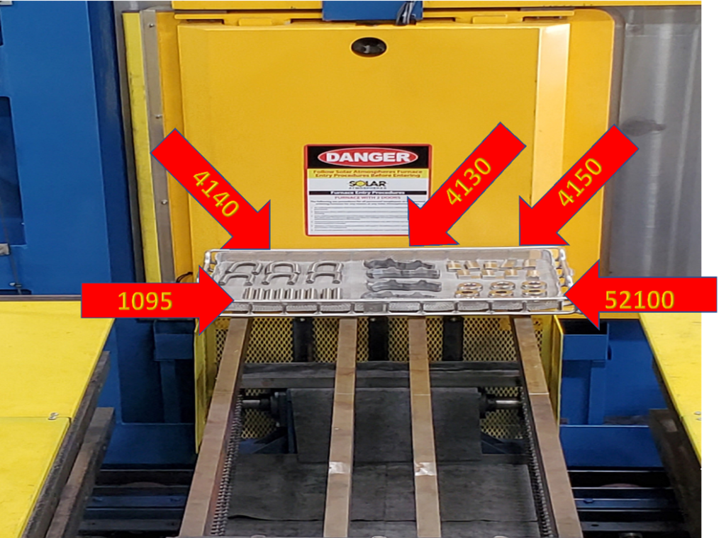
Figure 3. A display of a variety of parts which can be processed in the same run Source: Solar Atmospheres of Western PA
The next generation of oil quench furnaces should also finally provide metallurgical and quality engineers the ability to thermocouple the oil quenched parts in accordance with AMS2750 Rev H standards. Being able to monitor part temperature with up to twelve (12) data points, as defined by the latest AMS2750 revision, ensures thorough and precise thermocouple monitoring, bolstering control and repeatability.
Lastly, in a hermetically sealed furnace, another layer of control should be established through installing an internal camera. With “eyes” into the furnace, the operator will be able to watch the load transfer in real time from a control panel.
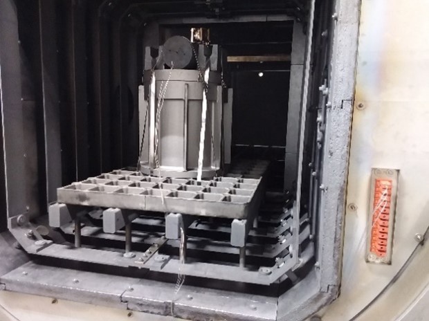
Figure 4a and 4b. Thermocoupled parts Source: Solar Atmospheres of Western PA
These operational attributes are on full display in the example of an automated austenitized cycle: At the completion of the cycle, the specially-designed transfer mechanism delivers precisely heated parts from the hot zone to the 3000-gallon oil quench chamber consistently within 20 seconds — all without the expulsion of flames and the discharge of smoke.
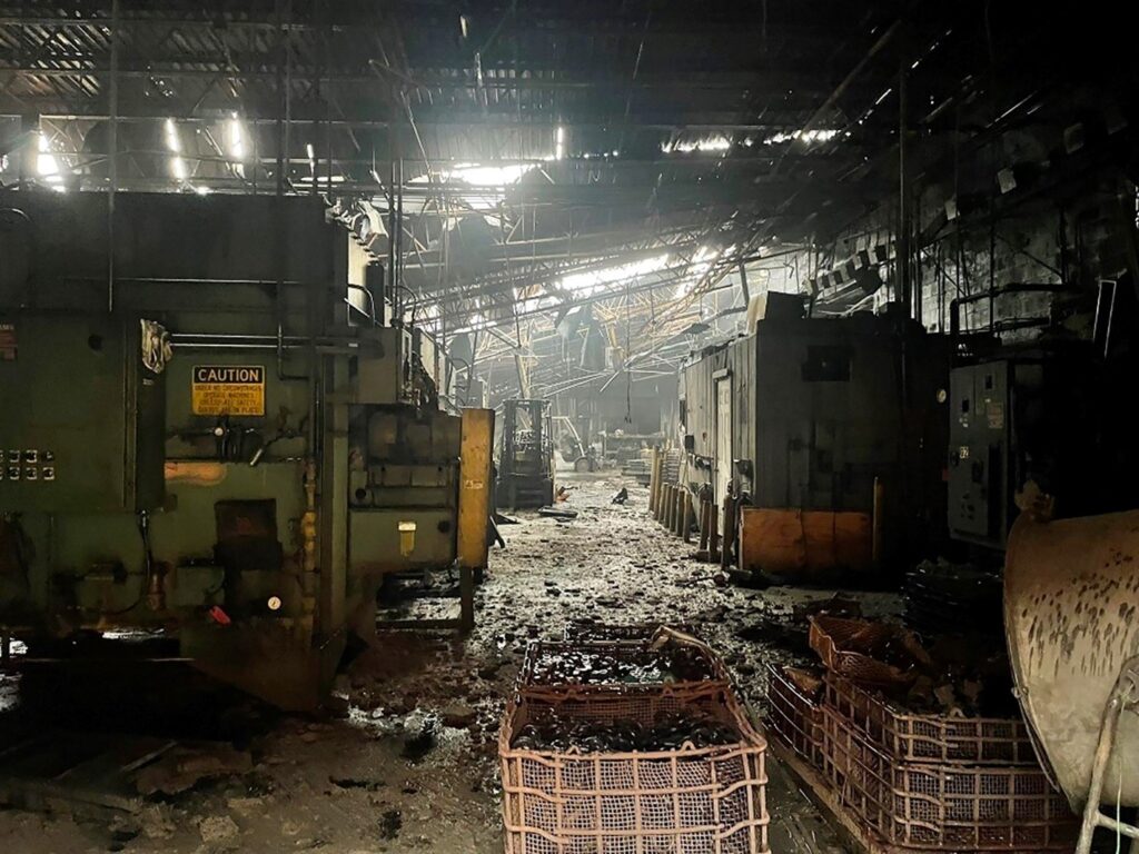
Oil flames and smoke are no longer acceptable realities in heat treatment operations. Unfortunately, the heat treating industry has been misled in the belief that a catastrophic disaster will never happen to them. There have been multiple “total losses,” mostly due to oil quench fires and explosions. Recently, it is well known that if an insurance adjuster sights a flame or smoke within a plant, they are reluctant or may even refuse to write the policy.
Vacuum furnaces offer a safe, contained alternative to the harmful open emissions and dangerous working conditions. For operations where the safety and the well being of the workforce are paramount, vacuum furnaces eliminate the risks associated with open flame exposure, explosivity, and skin burns.
Yet the next generation of vacuum oil quench furnaces should also open at both ends at the end of a cycle to expose it to atmosphere. Full air exchange mitigates the potential hazards of confined spaces.
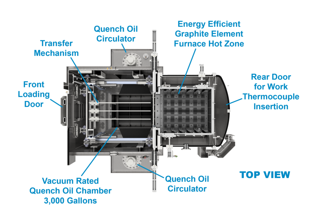
Figure 5. Top view showing innovative design features for the next generation of vacuum oil
quench furnaces Source: Solar Atmospheres of Western PA
Meeting Environmental Demands
With ever more stringent environmental regulations, the next generation of vacuum oil quench furnaces will play a pivotal role in reducing the carbon footprint of the heat treating industry. It has been estimated that 80% of fuel used for heat treatment could be replaced by electricity, thus drastically reducing CO2 emissions: “When you burn something that contains carbon, you get carbon dioxide that you either must take care of or release into the atmosphere. With electric heating, you do not have any exhaust.”
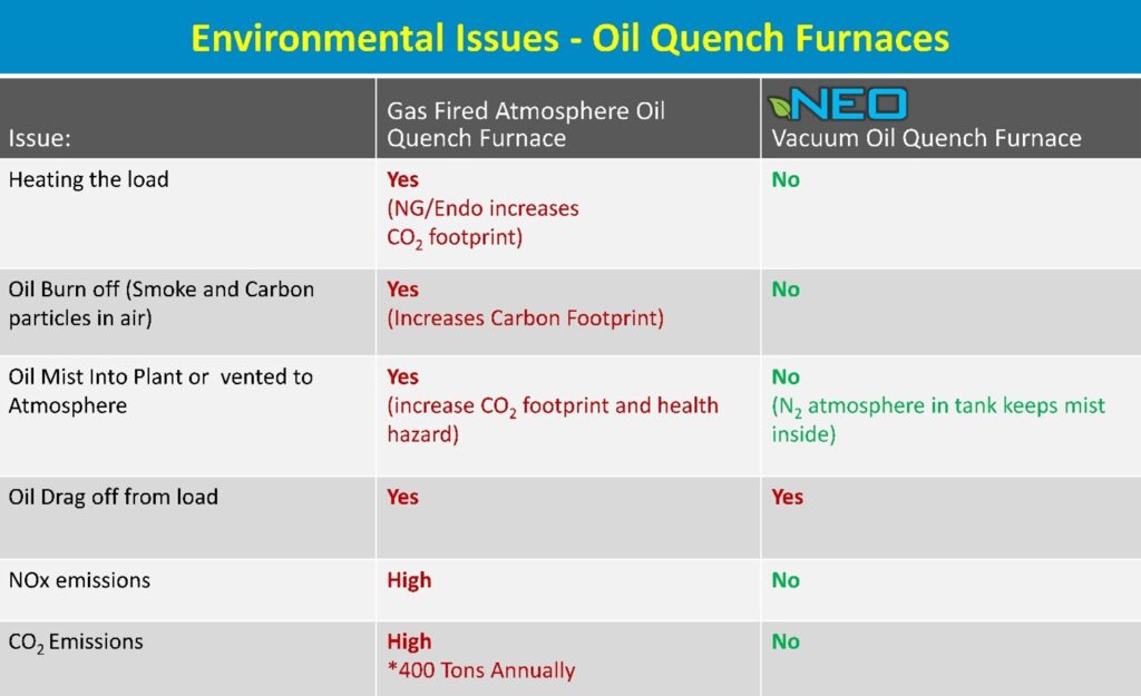
The second column in the chart on page 30 addresses the multiple environmental concerns associated with traditional batch IQ gas-fired oil quenching furnaces. The third column outlines the advantages of the design for the next generation of oil quench furnaces, which embraces electric heating as a sustainable alternative to fossil fuels. As sustainability pressures continue to mount, governments, clients, and primes alike will continue to flow down requirements on how heat treaters plan to reduce their carbon footprints.
Figure 6. Safety hazards in operating atmosphere furnaces Source: The Monty
Conclusion
As the demands for metallurgical precision, safety, and environmental sustainability continue to mount, Solar’s new vacuum oil quench furnace emerges as a representative of the next generation of vacuum oil quenching technology. Characterized by unparalleled efficiency, precision, and sustainability, such furnaces will continue to lead the industry toward a future defined by cleanliness, safety, and environmental stewardship.
Table 1. Data from the AICHELIN Group Source: Solar Atmospheres of Western PA
References
Kanthal, “Heat Treatment CO2 Emissions cut by 50 percent by using electricity” (April 2019), https://www.kanthal.com/en/knowledge-hub/inspiring-stories/heat-treatment-co2-emissions-cut-by-50-percent-by-using-electricity/.
Aichelin Group, “CO2 Footprints and the Heat Treat Industry,” The Monty (January 2024).
About the Author:
Robert Hill, FASM President Solar Atmospheres of Western PA Solar Atmospheres of Western PA
Robert Hill, FASM, began his career with Solar Atmospheres in 1995 at the headquarters plant in Souderton, PA. In 2000, Hill was assigned the responsibility of starting the second plant in Hermitage, PA, where he has specialized in the development of large furnace technology and titanium processing capabilities. Additionally, he was awarded the prestigious Titanium Achievement Award in 2009 by the International Titanium Association.
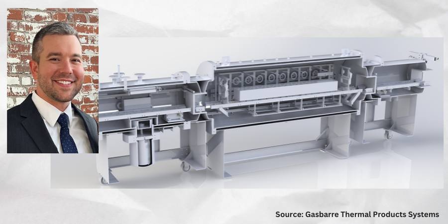
Adapting to new processing demands puts traditional equipment to the test. Can single-chamber solutions keep up, or will applications require different equipment options for efficient processing? In today’s Technical Tuesday, Bryan Stern, product development manager at Gasbarre Thermal Processing Systems, addresses the advantages multi-chamber isolated heat vacuum furnaces bring to the floor.
This informative piece was first released inHeat Treat Today’sNovember 2024 Vacuum print edition.
Do You Hear That? It’s the Sound of Change . . .
In the evolving landscape of vacuum heat treatment, single-chamber batch furnaces have long been the cornerstone of material processing. However, with more traditional processes shifting to vacuum, rising energy costs, and increasing environmental pressure, the disadvantages of that approach are emphasized, enhancing the appeal of alternative technologies. Multi-chamber vacuum equipment, while not new to the industry, offers significant solutions to inefficiencies and challenges faced by single-chamber systems. With advances in technology, improved operational planning, and an increasingly competitive market, multi-chamber isolated heat furnaces are becoming a more viable choice.
What Is an Isolated Heat Vacuum Furnace?
An isolated heat vacuum furnace keeps the heat chamber separate from the ambient atmosphere throughout the process, including loading and unloading. This allows the heated zone to maintain a stable temperature and vacuum between cycles, unlike single-chamber furnaces, which must heat up and cool down for each new load. Key components of this furnace type include an additional evacuation chamber, a dynamic sealing door, and a mechanism for moving the workload between chambers. While multi-chamber isolated heat furnaces may be batch or continuous, the above features fundamentally distinguish them from single-chamber batch equipment. This difference is more than just a technical nuance; it has profound implications for operations and efficiency.
The widespread use of single-chamber vacuum furnaces has significantly shaped the design and operation of vacuum furnaces today. But it is important to remember some of the challenges to this approach that we often take for granted.
Energy Efficiency Has Entered the Chat
Single-Chamber Challenge
In single-chamber systems, the entire furnace must go through a full cycle of loading, evacuation, ramping, soaking, cooling, and unloading for every batch of parts. This adds significant “dead time” on either side of the thermal process. In addition to pump-down time, ramping from room temperature typically adds 1–2 hours to the cycle time before soaking which creates a barrier to throughput. Another drawback is that the energy required to heat the furnace is thrown away after every cycle. Due to the high thermal capacity of materials like graphite and molybdenum, this is not inconsequential. With 100% thermal efficiency defined as only consuming the energy required to heat the work and fixturing, single-chamber batch furnaces typically operate in a thermal efficiency range of around 30%–50%.
Isolated Heat Advantage
In an isolated heat furnace, the work zone remains at temperature and the energy required to heat the furnace is not thrown away. Additionally, the introduction of work to a preheated work zone allows the load to be heated more quickly, reducing the time required to achieve temperature and reducing holding losses. While multi-chamber batch furnaces experience some savings, they still consume excess energy since the heat cage is empty during unloading, loading, and evacuation. Continuous configurations, however, see significant improvement with only holding losses and the energy required to heat the work and fixturing being consumed. These advantages mean that continuous furnaces typically operate in a thermal efficiency range of 45%–65%. The result is a 15%–35% energy efficiency improvement over the majority of existing equipment.
The tension of designing a single-chamber furnace to handle both heating and cooling in the same space presents substantial challenges. Insulation pack thickness is often limited to balance the need for quick pump-down. Gas nozzle penetrations through the insulation pack create direct radiation losses. This erodes thermal efficiency, adds thermal mass, and restricts gas flow during cooling. These conflicting design priorities often lead to unsatisfactory compromises and fluctuating designs. Between the additional energy to heat and cool and increase power demand at temperature, there are a lot of energy savings being left on the table.
Isolated Heat Advantage
Because the heating and cooling take place in separate locations, multi-chamber isolated heat equipment benefits from the ability to have dedicated designs tailored at each work position. More insulation can be used as conditioning time is not a significant consideration. Additionally, the insulation can be designed without penetrations, further reducing losses. Moving the work to a dedicated cooling position removes restrictions to gas flow and allows the work to radiate directly to the cold wall. This is especially beneficial at the beginning of a quench when the work is at high temperature. This can allow cooling rates to be achieved with lower quench pressures and smaller quench motors.
Thermal Cycling: Here We Go Again . . .
Single-Chamber Challenge
A single-chamber furnace must be built to endure extreme thermal cycling again . . . and again. This requires detailed design consideration to account for thermal shock, expansion, ratcheting, creep, and low-grade oxidation — all of which contribute to maintenance and replacement cost for expensive, long lead refractory components.
Isolated Heat Advantage
Since the heated portion of the furnace remains at stable temperature and vacuum, internal components are not subject to the same destructive forces. An isolated heat cage can remain in service much longer before requiring service or replacement. It also decreases the likelihood of sudden and unexpected equipment failure. Increasing the lifespan of the most expensive consumable assembly in the furnace is an incredibly valuable advantage that is frequently overlooked.
Find more on this topic in Heat Treat Radio episode #110. Bryan discusses the shift from single-chamber batch furnaces to isolated heat vacuum furnaces and speaks to some of the advantages mentioned in this article. Click the image to watch, listen, and learn on Heat Treat Radio.
Throughput and Load Size: Can They Help?
Single-Chamber Challenge
Single-chamber batch vacuum processing is notorious for the long cycle times and resulting limited throughput. One way to reduce the costs of the wasted energy and dead time is to increase the load size to distribute the cost over more work. While this can increase capacity and reduce the cost per part, it is counterproductive to many objectives of the heat treating process. As the load size increases, it becomes more difficult to maintain thermal and process uniformity across parts at the surface versus the center of the load. This is especially problematic for densely packed loads. Loads take longer to soak out to a uniform temperature, extending cycle times. Similarly, it is difficult to achieve rapid and uniform cooling rates which can lead to higher quench pressures, larger cooling motors, or underutilizing the work envelope.
Isolated Heat Advantage
While multi-chamber batch isolated heat furnaces experience many of the other advantages discussed in this article, throughput is where continuous configurations really shine. Because separate loads are being processed simultaneously, similar or greater throughputs can be achieved with much smaller load sizes. For instance, a process with a two-hour soak would typically require around a five-hour total cycle time in a single-chamber furnace. That same process could be segmented in a continuous furnace indexing loads in as little as 15 minutes, depending on the configuration of the equipment (see Figure 3). With a throughput ratio of 20:1, each load would only need to be 1/20th of the batch load to achieve the same throughput. With these mechanics, it quickly becomes apparent how continuous processing is capable of achieving much greater throughput while benefiting from the uniformity of smaller load sizes as well as the other advantages discussed.
Increasing the capacity of a single-chamber production line necessitates adding additional discrete furnaces. This means that all of the equipment systems are duplicated. Each furnace means another chamber, pumping system, manifolds, quench motor, VFD, control cabinet, certifications, instrument calibrations, etc. There really is no economy of scale available to help facilitate high volume production.
Isolated Heat Advantage
For most processes, increasing the capacity of a continuous multi-chamber furnace only requires adding additional heated work positions to shorten the index rate. All other auxiliary equipment and infrastructure can serve double-duty, and redundant systems and maintenance are avoided. This applies the cost directly to the necessary equipment (heat cage, elements, power supply, etc.). The resulting economy of scale often makes continuous equipment a far greater value proposition for high-volume applications that would otherwise require multiple furnaces.
Vacuum Performance: Don’t Reduce Me Like That!
Single-Chamber Challenge
Because single-chamber batch furnaces are exposed to air and humidity between each cycle, they require a higher vacuum (i.e., lower pressure) to achieve the purity required for a given process. This is because even though the furnace is evacuated to a low pressure, the remaining atmosphere is still primarily comprised of oxidizers in the form of residual air and water molecules desorbing from the internal surfaces of the furnace. Achieving the high vacuum levels required to achieve the necessary reducing atmosphere in a reasonable time can result in additional pumping equipment such as a booster or diffusion pump. This adds to system complexity, upfront cost, maintenance, and operating cost. Unfortunately, vacuum processes are often developed in, and organized around, single-chamber batch processing, so the actual purity requirement often gets distilled into an ultra-low vacuum level on the process specification. Consequently, these aggressive vacuum specifications are carried over to other types of equipment where they may not be necessary to achieve the same results.
Isolated Heat Advantage
Because the heat cage remains under vacuum throughout the process, there is less exposure to atmospheric contaminants. This allows oxidizing constituents to decay to very low levels leading to improved vacuum purity. Even though the absolute pressure is higher, the makeup of the remaining atmosphere is primarily inert. Given time for desorption to decay, it is entirely possible to have a purer environment at a higher pressure without requiring the complex pumping systems necessary in a single-chamber batch furnace. Reduction levels associated with diffusion pumping in single-chamber furnaces can be achieved at higher pressures with a two-stage or even single-stage pumping systems in an isolated heat furnace. This is one of the most overlooked and misunderstood advantages of isolated heat processing.
The Shift Toward Isolated Heat Furnaces
Despite the many challenges associated with single-chamber batch processing, the prevalence of these furnaces has remained high due to their simplicity and familiarity. So, why are multi-chamber furnaces gaining traction now?
“There is a pending perfect storm of market conditions poised to tip the scales.”
There is a pending perfect storm of market conditions poised to tip the scales. More and more traditional processes are shifting to vacuum for its long list of advantages, including tighter process control, flexibility, safety, insurance liability, and improved working environment, just to name a few. This push to convert more processes is driving a need to optimize efficiency and improve cost. The existing approach has known intrinsic inefficiencies and a limited growth path for improvement.
As more heat treaters either experience or compete with the benefits of multi-chamber isolated heat equipment, adoption will continue to accelerate.
Challenges and Considerations
While isolated heat furnaces offer numerous advantages, they are not without challenges. These systems are more complex, require a detailed specification process, and may not be suitable for very large components, intermittent operations, or applications requiring a high degree of flexibility. Many of the advantages of multi-chamber equipment show up in operating and maintenance costs. These benefits can be missed if these costs are not properly accounted for in the ROI analysis phase. Overemphasizing upfront costs can mean missing out on a much better return on investment for equipment with installation life in the range of 20–30 years.
Applications and Future Prospects
Isolated heat vacuum furnaces are not industry specific; rather, they offer advantages across a wide range of applications. Processes characterized by short cycle times benefit because a greater percentage of the floor-to-floor time is dead time and can be recovered, improving equipment utilization. Processes characterized by long cycle times benefit because they can be segmented and indexed at much faster rates, increasing throughput. Surface treatments can benefit from the process uniformity of smaller load sizes without sacrificing throughput. High-volume production environments, in particular, stand to gain the most. Whenever there is a need for more than one batch furnace or where there are numerous small parts in a large work zone, the efficiency and cost savings of continuous isolated heat furnaces truly stand out.
Conclusion
The industry’s focus on efficiency, reduced emissions, and lower operating costs makes isolated heat vacuum furnaces a promising direction for the future. While single-chamber furnaces will still have their place, isolated heat furnaces are becoming more prevalent for many heat treatment processes. Offering superior energy efficiency, better process control, and a more sustainable approach to thermal processing, these furnaces will enable manufacturers to provide high quality, cost-effective solutions that meet today’s market demands and future challenges.
About the Author:
Bryan Stern Product Development Manager Gasbarre Thermal Processing Systems
Bryan Stern has been involved in the development of vacuum furnace systems for the past eight years and is passionate about technical education and bringing value to the end-user. Currently product development manager at Gasbarre Thermal Processing Systems, Bryan holds a B.S. in Mechanical Engineering from Georgia Institute of Technology and a B.A. in Natural Science from Covenant College. In addition to being a member of ASM, ASME, and a former committee member for NFPA, Bryan is a graduate of the MTI YES program and recognized in Heat Treat Today’s40 Under 40 Class of 2020.
The heat treat industry is rich with knowledgeable leaders, resourceful problem solvers, and innovative teams. One of our favorite things to do here atHeat Treat Today is to draw attention to the wealth of expertise in the field, so we are pleased to launch the Voices in Heat Treat series, pointing readers to a treasure house of recorded interviews and discussions diving into the fundamentals of thermal processing.
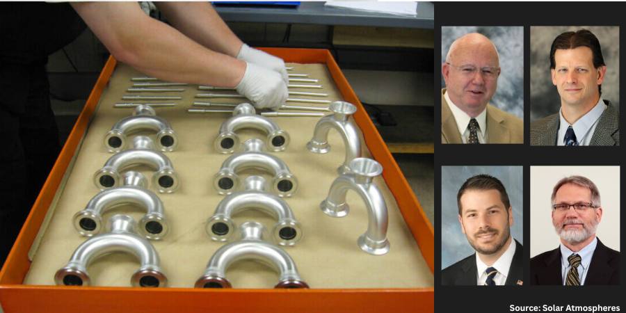
In this and coming articles drawn from the audio library at Solar Atmospheres, we will summarize topics on everything from basic heat treating how-tos, preventative maintenance, and troubleshooting to the history of hot zone designs, temperature uniformity surveys, and the distinctions to take into consideration when processing different kinds of metals and alloys. In today’s installment, our industry experts focus on vacuum brazing and the uniqueness of heat treating titanium.
In the premiere article of this series, Bill Jones, founder and CEO of Solar Atmospheres and Solar Manufacturing, interviews industry leaders about the advantages of vacuum furnace brazing. Read the highlights of their discussion about the process, in particular when used with stainless steel and titanium. The summary of a fourth episode recorded earlier has been added, expanding on the topic of the advantages of processing titanium in a vacuum furnace. The experts are Calvin Amenheuser, vice president of the Hatfield plant, and Mike Paponetti, sales manager of the southeast. Jim Nagy, senior vice president of Solar Manufacturing, hosts the episodes. A summary of each conversation is below, followed by links that will take you directly to that podcast episode.
Bill Jones and the Team Speak on Vacuum Brazing, a 3-Part Series
“Advantages of Vacuum Furnace Brazing”
December 2015
Brazing to form strong metallurgical bond where the brazed joint becomes a sandwich of different layers, each linked at the grain level
This episode is the first in a series on vacuum furnace brazing, with an overview of different types of brazing processes and why vacuum furnace brazing is superior to other joining methods, particularly torch brazing and welding.
The conversation explores various reasons why a vacuum furnace is well-suited to perform brazing because it provides:
a controlled, consistent atmosphere cycle after cycle
uniform heating throughout the hot zone
a controlled rate of heating
the elimination of air to prevent the formation of oxidation of the metal
Vacuum Furnace Brazing vs. Alternative Methods
Both Cal Amenheuser and Mike Paponetti speak about vacuum brazing being a superior process to alternative methods. Mike noted that torch brazing is effective for low volume loads, but the process risks flux entrapment and could produce messy, overheated and possibly carburized parts. In contrast, vacuum furnace brazing allows for higher volume loads, providing a repeatable process, precise temperature measurements, and versatility.
Brazing applications from parts to rockets
Calvin added that while welding melts the materials and produces a strong joint, the surrounding material is weaker. With vacuum furnace brazing, the brazed joint is just as strong or stronger afterward as before.
Finally, the panelists compared how batch vacuum furnace brazing eliminates distortion that is typical with torch brazing and welding because of hot zone uniformity. A batch furnace operator can modify the process to meet the demand of the load, and furnace charts provide proof of reveal what exactly happened during the run so that successful recipes can be repeated.
In this episode, second in the series on the vacuum furnace brazing, the Solar team reconvened to discuss advantages of and concerns with nickel-based and copper-based brazing alloys.
All agree that nickel-based alloy offers a cleaner braze but emphasize precautions must be put in place to avoid metal erosion and cracking. While readily available and a good match for low carbon steel, copper flashes during the braze. Inert gas is recommended to decrease evaporation of the copper-based alloy.
“Processing Titanium in Vacuum Furnaces: Active Brazing of Titanium in a Vacuum Furnace”
April 2016
In this third and final episode on the topic of vacuum furnace brazing, Bill Jones, Calvin Amenheuser, and Mike Paponetti consider significant challenges to brazing titanium, which is the need to reduce surface oxide to allow the process to take place and why active brazing is suggested as a means to meet that challenge. What follows is an informative discussion on composites that allow producing companies add to the material, like hydrated titanium, zirconium, and indium, to help overcome oxides, which are effective at wedding to the surface.
“Processing Titanium in Vacuum Furnaces: Advantages”
February 2013
175,000 pounds of 6Al-4V titanium in Solar’s 48-foot-long vacuum furnace
Although recorded earlier than and thus separately from the series on vacuum furnace brazing, this summary of an episode is included in this article to provide context about the advantages of processing titanium in a vacuum furnace. This is a solo Bill Jones episode.
Bill Jones highlights how vacuum furnaces provide a pure atmosphere for processing titanium compared to an argon atmosphere, saving machining costs and time. Additionally, vacuum processing uses forced inert gas quenching to cool titanium as opposed to water quenching which results in a more uniform result and eliminates part distortion. Finally, fixturing parts properly in a vacuum furnace with graphite allows heat treaters to preserve the part shape and avoid movement.
Bill Jones Founder & CEO Solar Atmospheres, Solar Manufacturing Source: Solar AtmospheresCalvin Amenheuser Vice President of Operations, Souderton plant Solar Atmospheres Source: Solar AtmospheresMichael Paponetti Sales Manager of the Southeast Solar Atmospheres, Inc. Source: Solar AtmospheresJim Nagy Senior Vice President Solar Manufacturing, Inc. Source: LinkedIn
The Heat Treat Doctor® has returned to offer sage advice to Heat Treat Today readers and to answer your questions about heat treating, brazing, sintering, and other types of thermal treatments as well as questions on metallurgy, equipment, and process-related issues.
Product failures (Figure 1) can often be traced to deficiencies in design, materials, manufacturing, quality, maintenance, service-related factors, and human error to name a few. Examples of failures include misalignment, buckling, excessive distortion, cracking, fracture, creep, fatigue, shock, wear, corrosion, and literally hundreds of other mechanisms. Let’s learn more.
Figure 1. Image of damage to left fuselage and engine; fire damage to nacelle. Source: National Transportation Safety BoardFigure 2.: Model of material science depicting— key interactions and /interrelationships Source: The HERRING GROUP, Inc.
Whatever the source, it is important to recognize that it is next to impossible to separate the product from the process. Performance, design (properties and material), metallurgy (microstructure), heat treatment (process and equipment), and maintenance are all interconnected (Figure 2).
When considering ways to prevent failures from occurring, one must determine the factors involved and whether they acted alone or in combination with one another. Ask questions such as, “Which of the various failure modes were the most important contributors?” and “Was the design robust enough?” and “Were the safety factors properly chosen to meet the application rigors imposed in service?” Having a solid engineering design coupled with understanding the application, loading, and design requirements is key to avoiding failures. If failures do happen, we must know what contributed to them.
Let’s review a few of the more common failure modes.
Fracture Types on a Macroscopic Scale
Applied loads may be unidirectional or multi-directional in nature and occur singularly or in combination. The result is a macroscopic stress state comprised of normal stress (perpendicular to the surface) and/or shear stress (parallel to the surface). In combination with the other load conditions, the result is one of four primary modes of fracture: dimpled rupture (aka microvoid coalescence), cleavage, decohesive rupture, and fatigue.
Virtually all engineering metals are polycrystalline. As a result, the two basic modes of deformation/fracture (under single loading) are shear and cleavage (Table 1). The shear mechanism, which occurs by sliding along specific crystallographic planes, is the basis for the macroscopic modes of elastic and plastic deformation. The cleavage mechanism occurs very suddenly via a splitting action of the planes with very little deformation involved. Both of these micro mechanisms primarily result in transgranular (through the grains) fracture.
Fracture Types — Ductile and Brittle
Numerous factors influence whether a fracture will behave in a ductile or brittle manner (Table 2). In ductile materials, plastic deformation occurs when the shear stress exceeds the shear strength before another mode of fracture can occur, with necking typically observed before final fracture. Brittle fractures occur suddenly and exhibit very little, if any, deformation before final fracture. (The following is based on information found in Wulpi, 1985.)
Ductile fractures typically have the following characteristics:
Considerable plastic or permanent deformation in the failure region
Dull and fibrous fracture appearance
Brittle fractures typically have the following characteristics:
Contact us with your Reader Feedback!
Lack of plastic or permanent deformation in the region of the fracture
Principal stress (or tensile stress) is perpendicular to the surface of the brittle fracture
Characteristic markings on the fracture surface pointing back to where the fracture originated
When examined under a scanning electron microscope, fracture surfaces seldom exhibit entirely dimpled rupture (i.e. ductile fracture) or entirely cleavage (i.e. brittle fracture), although one or the other may be more prevalent. Other fracture modes include intergranular fractures, combination (quasi-cleavage) fractures and fatigue fractures.
Fracture Types — Wear
Wear (Table 3) is a type of surface destruction that involves the removal of material from the surface of a component part under some form of contact produced by a form of mechanical action. Wear and corrosion are closely linked, and it is important not only to evaluate the failure but to take into consideration design and environment and have a good understanding of the service history of a component.
Fracture Types — Corrosion
Corrosion is the destruction of a component by the actions of chemical or electrochemical reactions with the service environment. The major types of corrosion include galvanic action, uniform corrosion, crevice corrosion, stress-corrosion cracking, and corrosion fatigue. The mechanisms and effects created by each of these are well documented in the literature, as in Fontana and Greene’s Corrosion Engineering (1985) and Uhlig’s Corrosion and Corrosion Control (1985). It is critical to understand that the effects of corrosion are present to some degree in every failure analysis, which is one of the reasons why protecting fracture surfaces is so critical when sending parts for failure analysis.
Table 1. Differences between shear and cleavage fracture (Data referenced from page 23 of Wulpi, see References.) Source: The HERRING GROUP, Inc.Table 2. Typical characteristics of ductile and brittle fractures Source: The HERRING GROUP, Inc.Table 3. General categories of wear Source: The HERRING GROUP, Inc.
Final Thoughts
To avoid failures or their reoccurrence, it is important to document each step in the design and manufacture process (including heat treatment). In addition, careful documentation of failures if/when they occur is of critical importance as is assembling a team of individuals from different disciplines to perform a comprehensive investigation. This includes a thorough failure analysis to assist in determining the root cause (there is only one) and to avoid it from happening in the future.
Fontana, M. G., and N. D. Greene. Corrosion Engineering, 3e. McGraw-Hill Book Company, 1985.
Herring, Daniel H. Atmosphere Heat Treatment, Volume Nos. 1 & 2. BNP Media, 2014/2015.
Lawn, B.R. and T. R. Wilshaw. Fracture of Brittle Solids. Cambridge University Press, 1975.
Shipley, R. J. and W. T. Becker (Eds.). ASM Handbook, Volume 11: Failure Analysis and Prevention. ASM International, 2002.
Uhlig, H. H. Corrosion and Corrosion Control. John Wiley & Sons, 1963.
Wulpi, Donald J. UnderstandingHow Components Fail. ASM International, 1985.
About the Author
Dan Herring “The Heat Treat Doctor” The HERRING GROUP, Inc.
Dan Herring has been in the industry for over 50 years and has gained vast experience in fields that include materials science, engineering, metallurgy, new product research, and many other areas. He is the author of six books and over 700 technical articles.
In this installment of the Controls Corner, we are addressing load configurations in a furnace. An industrial furnace is made up of multiple zones for the heating of the load. These zones are strategically placed to minimize heat losses and to give the best heat profile for the application (minimize hot and cold spots in the vessel). In this Technical Tuesday installment, guest columnist Stanley Rutkowski III, senior applications engineer at RoMan Manufacturing, Inc., highlights the differences between power controls based on voltage and current.
This informative piece was first released inHeat Treat Today’sSeptember 2024 People of Heat Treat print edition.
The utility company transmits power to the electrical grid in terms of “voltage” and “current.” Voltage is the pressure to push the current through the wires. The amount of voltage required is a function of the losses in the system (resistance, reactance, and impedance). Utility companies transmit this via the highest voltage available to minimize the current. By minimizing the current, the cross section of the conductors to transmit gets smaller and less costly to run over long distances. At an industrial facility, a step down transformer (distribution type) is used to change the high voltage from the utility company to plant voltage (and by the same ratio increase the current from low to high).
In the operations of a furnace, the term commonly used is power, which is a multiplication of two variables, voltage and current.
In the operations of a furnace, the term commonly used is power, which is a multiplication of two variables, voltage and current. The utility company transmits power in a three-phase configuration with 120 degrees difference between phases (typically labeled A-B, B-C, and C-A). Let’s take a brief look at four major load configurations.
Single-Phase Load
A single-phase load uses one of the three legs of the system in operation. This type of system is best used in three zone applications to try to balance the power of each zone to the utility. A single-phase load allows for the most control of a zone in a furnace as it is individually controlled, but potentially causes the most disturbances to the utility company.
Two-Phase Load (Scott-T)
A Scott-T system is a way to balance load a three-phase system but allow for two loads in operation. In a five zone furnace, you could configure a three-phase system for the middle three zones and a Scott-T system for the first and last zones (front and back). A Scott-T system has a single point of control for the two zones to have the least disturbances to the utility company.
Three-Phase Load
A three-phase load can be in different configurations, the most common being Delta and Wye. The differences between them are the vectors of the voltage and current. A Wye system has less voltage and more current while a Delta system has less current and higher voltage. Care needs to be taken to minimize potential circulating currents that can be created by the vectors of three-phase systems. The three-phase system is a single point of control for the loads and causes less disturbances to the utility company. Mixing of three-phase systems inside a furnace (Delta and Wye) can help further minimize disturbances to the utility company.
IGBT (Insulated-Gate Bipolar Transistor)
An IGBT (Insulated-Gate Bipolar Transistor) system is a hybrid system that uses a three-phase primary to create a single-phase load. This allows for the highest level of control while minimizing the disturbances to the utility company. This system also allows the usage of higher frequencies to shrink the footprint of the transformers, allowing the use of rectification to minimize inductance and minimize the high current runs to the load(s).
About the Author:
Stanley F. Rutkowski III Senior Applications Engineer RoMan Manufacturing, Inc.
Stanley F. Rutkowski III is the senior applications engineer at RoMan Manufacturing, Inc., working on electrical energy savings in resistance heating applications. Stanley has worked at the company for 33 years with experience in welding, glass and furnace industries from R&D, design, and application standpoints. For more than 15 years, his focus has been on energy savings applications in industrial heating applications.